

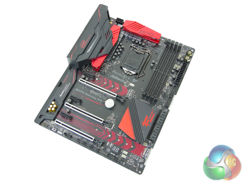
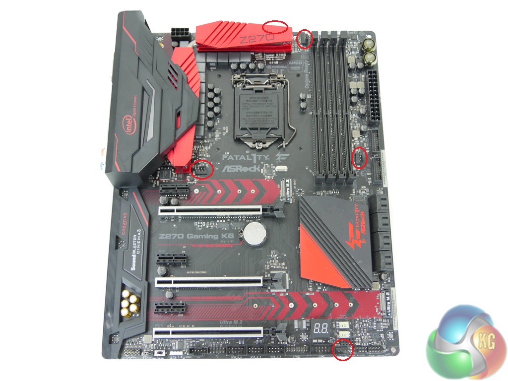
ASRock uses the standard ATX form factor for the Fatal1ty Z270 Gaming K6. As far as layout decisions go, ASRock sticks to the standard ATX styling.
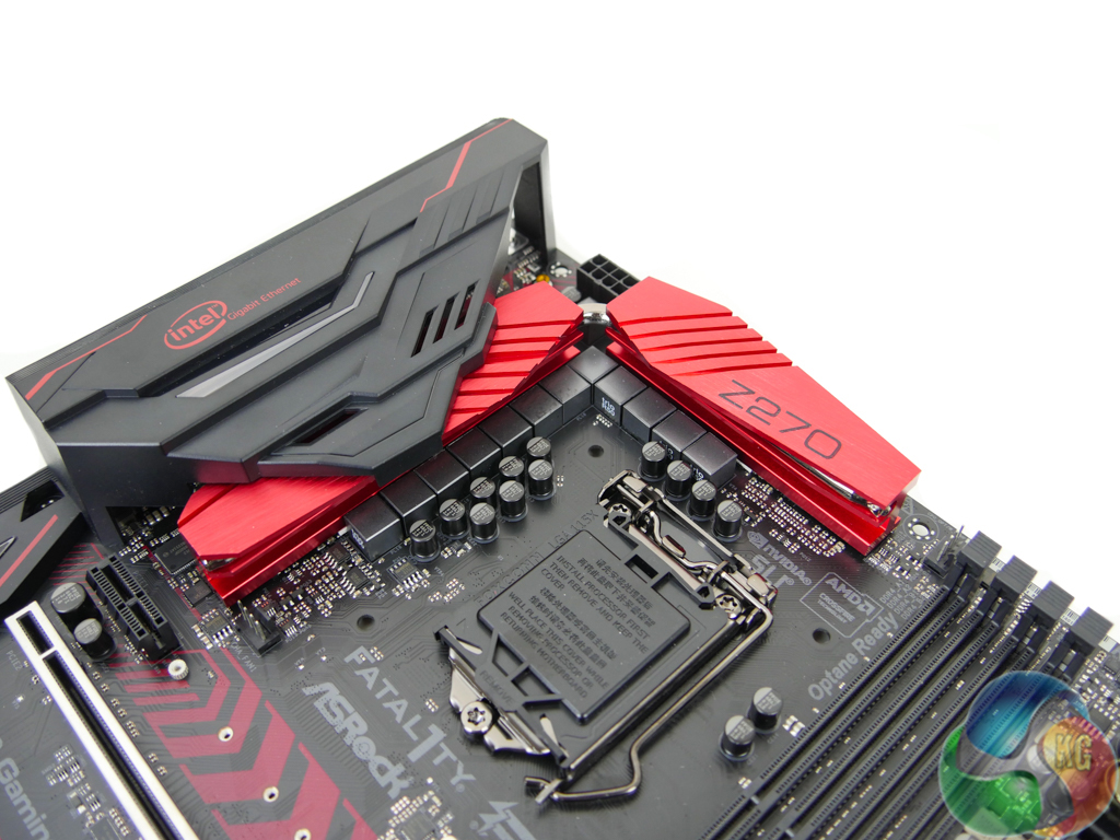
Red touches contrast the motherboard’s largely black appearance. An all-black PCB is good to see on a motherboard of this calibre, rather than a washed-out brown alternative. Capacitors and other components also continue the black styling. The VRM heatsink is a deep, shiny red colour which should look good inside a well-lit gaming system.
The Z270 Gaming K6 has three RGB LED locations; the rear IO cover, the audio section cover, and beneath the chipset heatsink. There is also a 4-pin AURA RGB header that can control external strips.
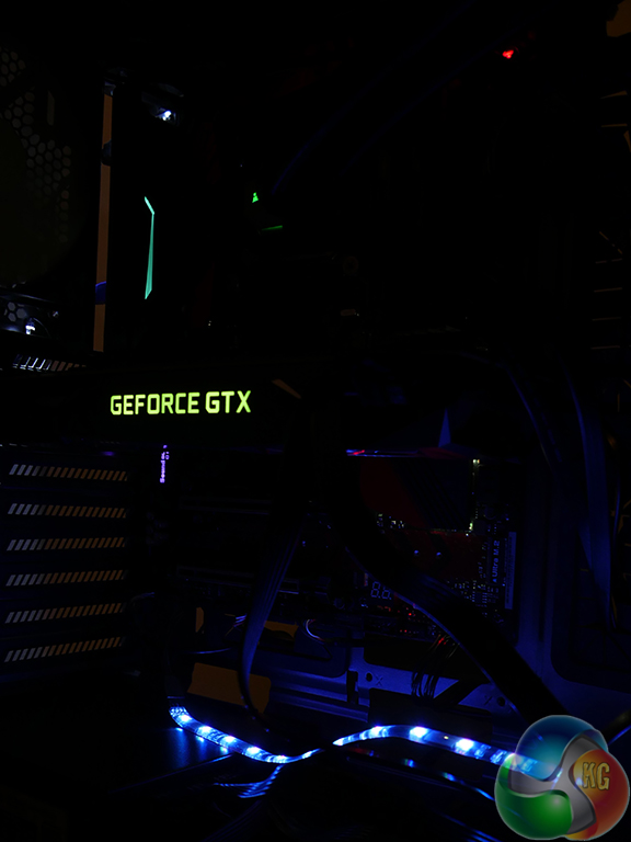
Control of the RGB LEDs is limited but a number of lighting modes are supported and the three different sections (and LED strip) can be set with distinct individual preferences. I found the colour accuracy to be poor for the chipset LEDs and these were also very dim and barely visible.
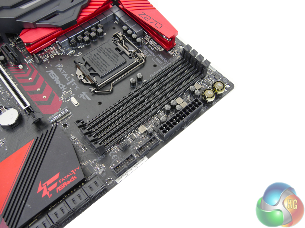
Four single-latch DIMM slots provide support for up to 64GB of dual-channel DDR4 memory using currently-available 16GB DIMMs. ASRock quotes memory frequency support of more than 3866MHz via overclocking. Frequencies this high are likely to rely upon a Kaby Lake CPU with a good IMC and a well-tuned BIOS profile devoid of memory-related bugs.
Dual internal USB 3.0 headers are provided using an ASMedia ASM1074 hub chipset and reside next to the 24-pin power connector. I like to see dual USB 3.0 headers as they provide additional flexibility to those who want more than two front panel USB 3.0 ports (which is particularly relevant with the rise in popularity of USB-powered VR headsets). And their motherboard positioning is ideal as the 24-pin area is generally the quickest route front a case’s thick front panel cable.
A single 4-pin fan header and power and reset onboard buttons are also located close the 24-pin area. Onboard buttons are ideal for out-of-chassis motherboard testing, be it for diagnostic or initial stability checking purposes.
Despite using the new Z270 chipset, the LGA 1151 socket is the same as that found on 100-series chipset motherboards. This is how older Skylake CPUs are also supported by Z270 motherboards. An IDT 6V41642B clock generator manages the BCLK frequencies and waveforms.
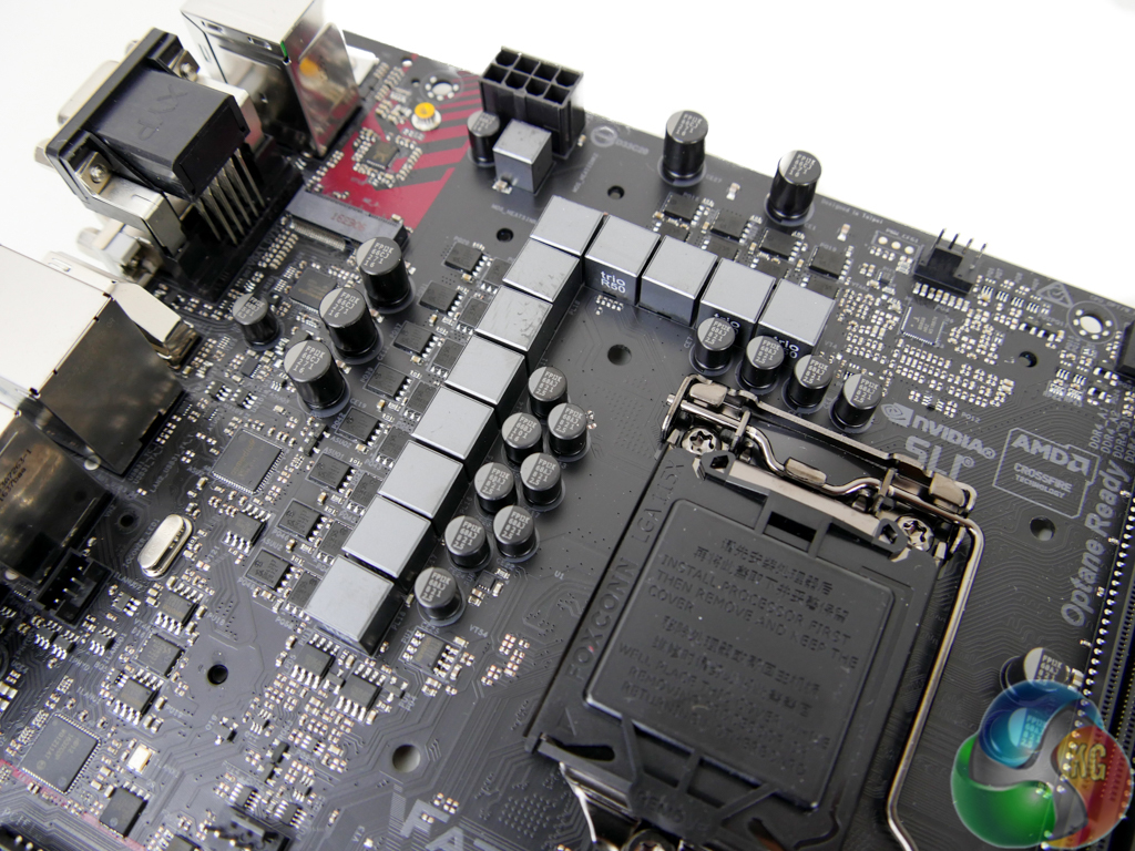
The well-cooled power delivery system consists of 12 primary phases for the CPU, iGPU, and miscellaneous system operations. Intersil’s ISL95856 hybrid-digital PWM controller is in charge of the power delivery system, aided by two ISL6625A dual MOSFET drivers. Sinopower SM4337 and SM4336 high- and low-side MOSFETs are used to shift power to the CPU and other rails. The 45A-rated inductors are marked ‘Trio R50’ and the capacitors are 12K-rated.
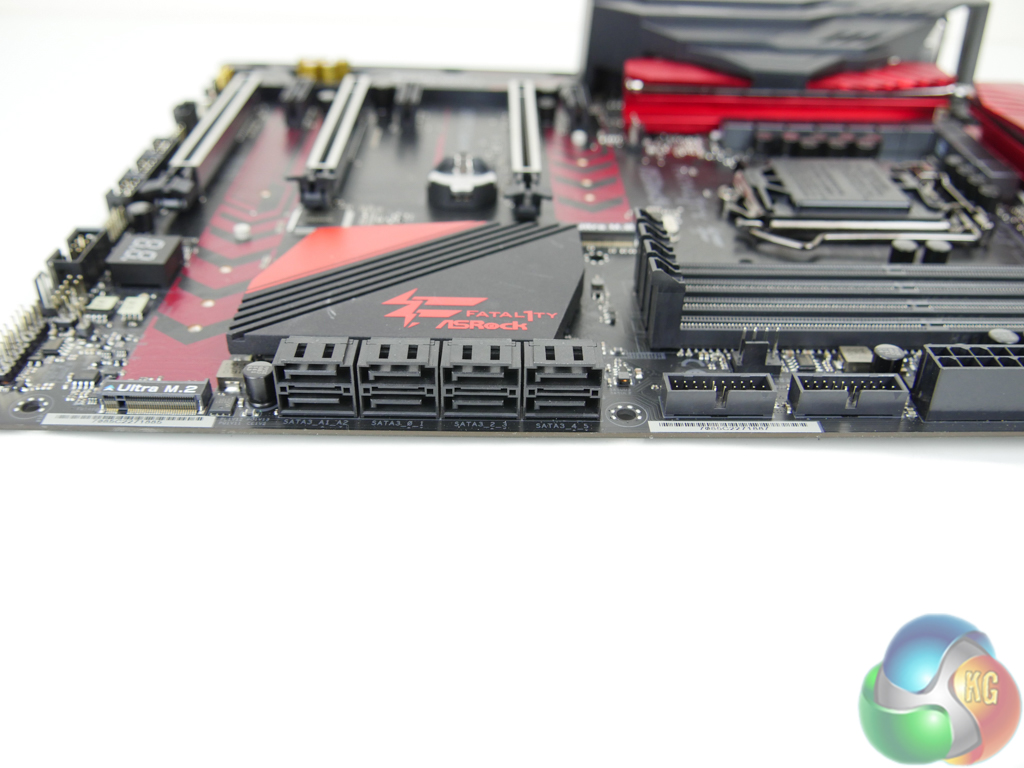
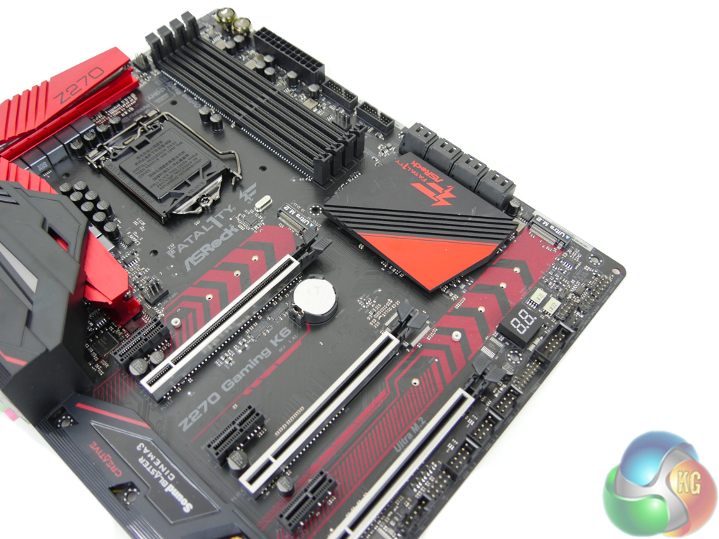
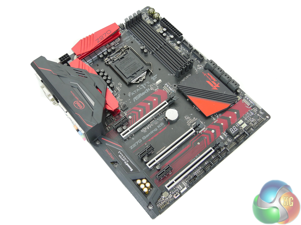
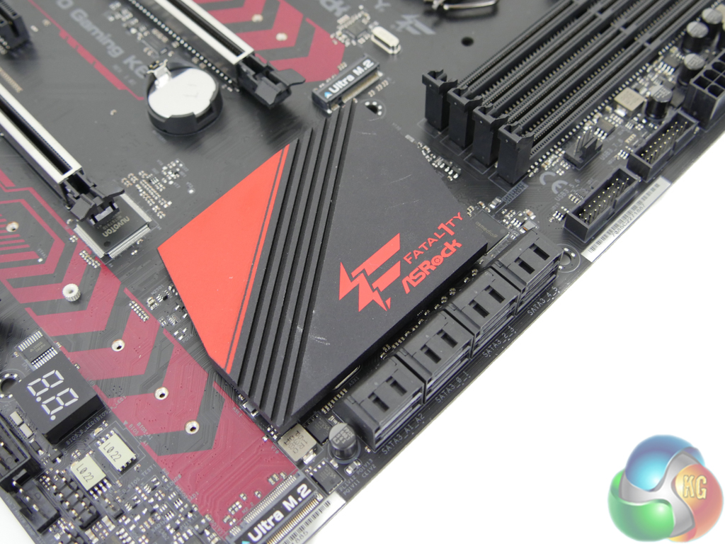
Eight SATA 6Gbps ports are mounted in a right-angled orientation. Six of the ports are provided through the Z270 chipset while the remaining pair comes from a slower ASMedia ASM1061 chipset and should be used after the Z270 connections have all been taken.
I like the inclusion of an additional SATA chipset as two pairs of Z270-powered SATA ports share their bandwidth with both of the M.2 connectors (depending upon the use of an M.2 PCIe or SATA device).
There is no SATA-Express, which most people will probably see as a good move. But I don't like the decision to omit it because its PCIe x2 bandwidth capability is ideal for powering front panel USB 3.1 Gen 2 devices. Until there is a valid internal USB 3.1 Gen 2 header, I believe that SATA-Express still deserves its place on motherboards.
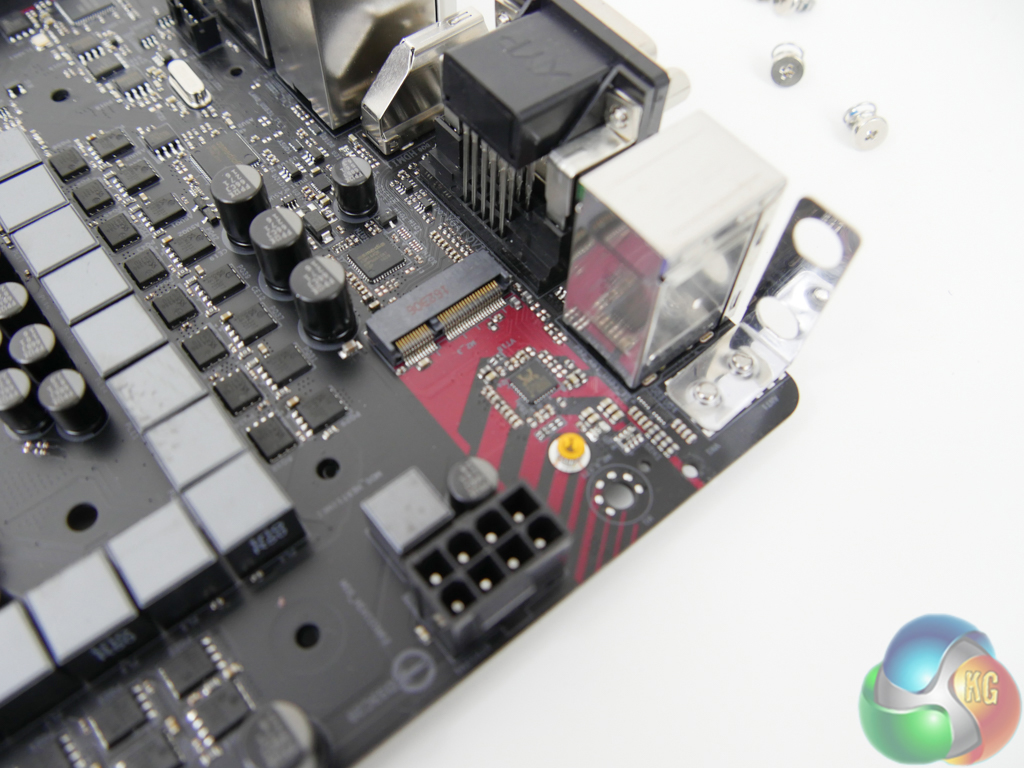
Both M.2 connectors support both SATA 6Gbps and PCIe 3.0 x4 32Gbps NVMe devices. The upper slot can handle devices up to 80mm in length while up to 110mm-long devices are supported in the lower slot. Intel Optane devices are supported as is RAID for dual M.2 PCIe SSDs being used simultaneously.
Using the M.2_1 slot renders SATA ports 0 and 1 unusable while the second M.2 slot will disable SATA ports 4 and 5 when in use.
There's no onboard U.2 port. I will not highlight this as a major negative, though, because U.2 devices are still scarce and positioning of the lower M.2 slot makes it ideal for use with an M.2-to-U.2 adapter card.
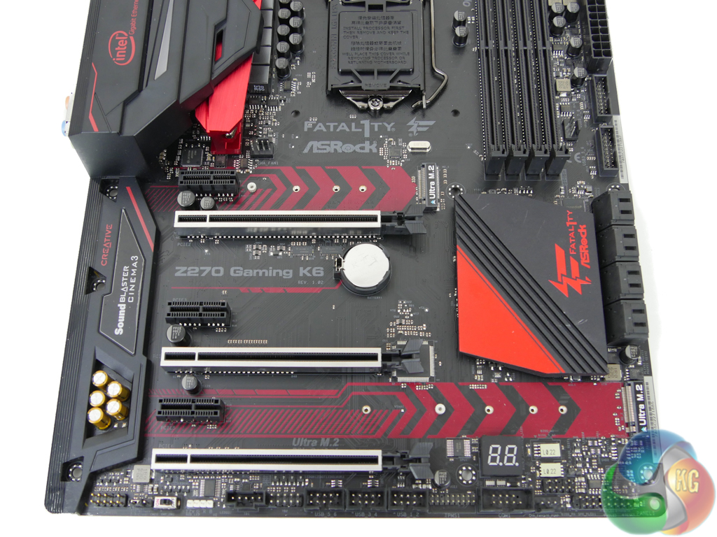
Three full-length, steel-plated PCIe slots are used for high-bandwidth expansion devices such as graphics cards. Steel reinforcement is good for preventing PCB flex, slot breakages, and EMI. The uppermost slot is hard-wired for up to 16 PCIe 3.0 lanes from the CPU while the second one is hard-wired for up to eight lanes. Using both slots together gives PCIe 3.0 x8/x8 SLI or CrossFire with a single-slot cooling gap (assuming dual-width graphics coolers).
That lowest full-length slot is wired for four PCIe 3.0 lanes. This makes it capable of housing a third graphics card for 3-card CrossFire but not for SLI due to the x8 link speed requirement. PCIe SSDs such as the Intel SSD 750 will also make sense to be housed in this lowest slot. With up to 24 chipset PCIe Gen 3 lanes, the Z270 chipset gives plenty of flexibility for add-in PCIe devices.
A trio of open-ended PCIe 3.0 x1 lanes are ideal for installing add-in cards such as those for game capture or WiFi. Making the slots open-ended is a move that I like to see as it allows older PCIe x2, x4, x8, or x16 cards to be installed in the slot if a user decides that full bandwidth is not necessary. Example situations could be using an old PCIe x8 RAID card in HBA mode for connecting multiple HDDs or perhaps using a discrete PCIe x16 GPU simply for additional display outputs rather than bandwidth-intensive operations.
A M.2 Key E slot hidden beneath the rear IO plastic cover is ideally situated for holding a WiFi card. One can hide a potentially ugly WiFi card and route the aerial cables with ease.
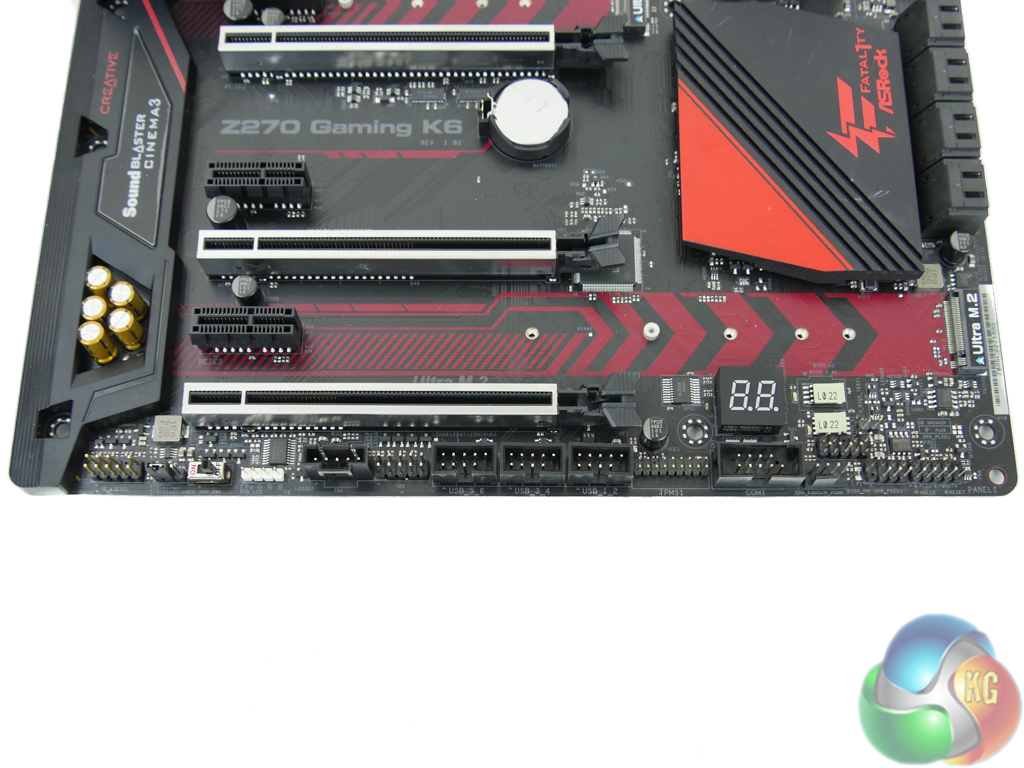
The usual set of headers is located on the motherboard’s bottom edge. ASRock provides three USB 2.0 headers, which I have no complaints about given the number of hardware peripherals that use the headers (NZXT peripherals and Corsair AIO coolers, for example). A physical XMP switch can be used for diagnostic purposes if the UEFI function is not working for any reason. Next to the switch is the clear CMOS jumper which is in a hard-to-access location.
ASRock mounts an AURA RGB LED headers which uses +12V, G, R, B pins. The two-digit LED debug display is an inclusion that I love to see thanks to its worth when troubleshooting. Dual soldered BIOS chips give redundancy against a crash on the primary profile but the soldered mount requires a dedicated tool for chip replacement.
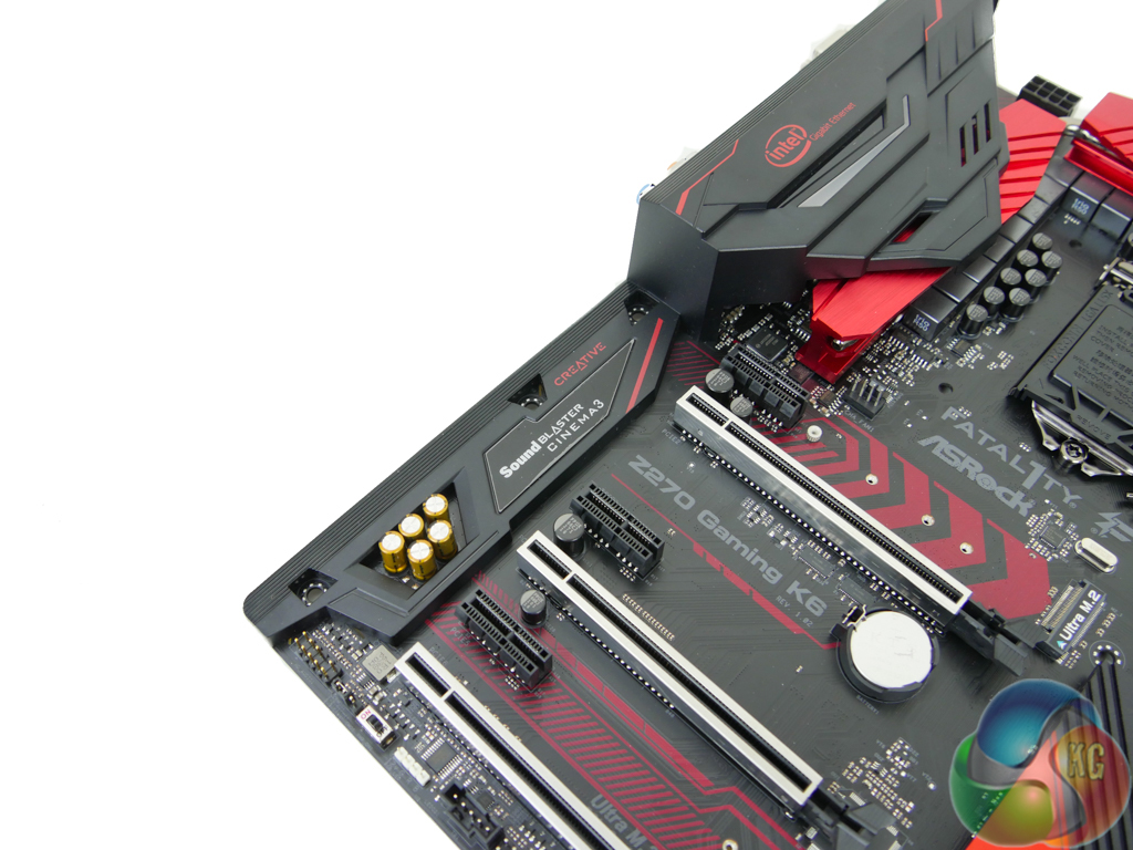
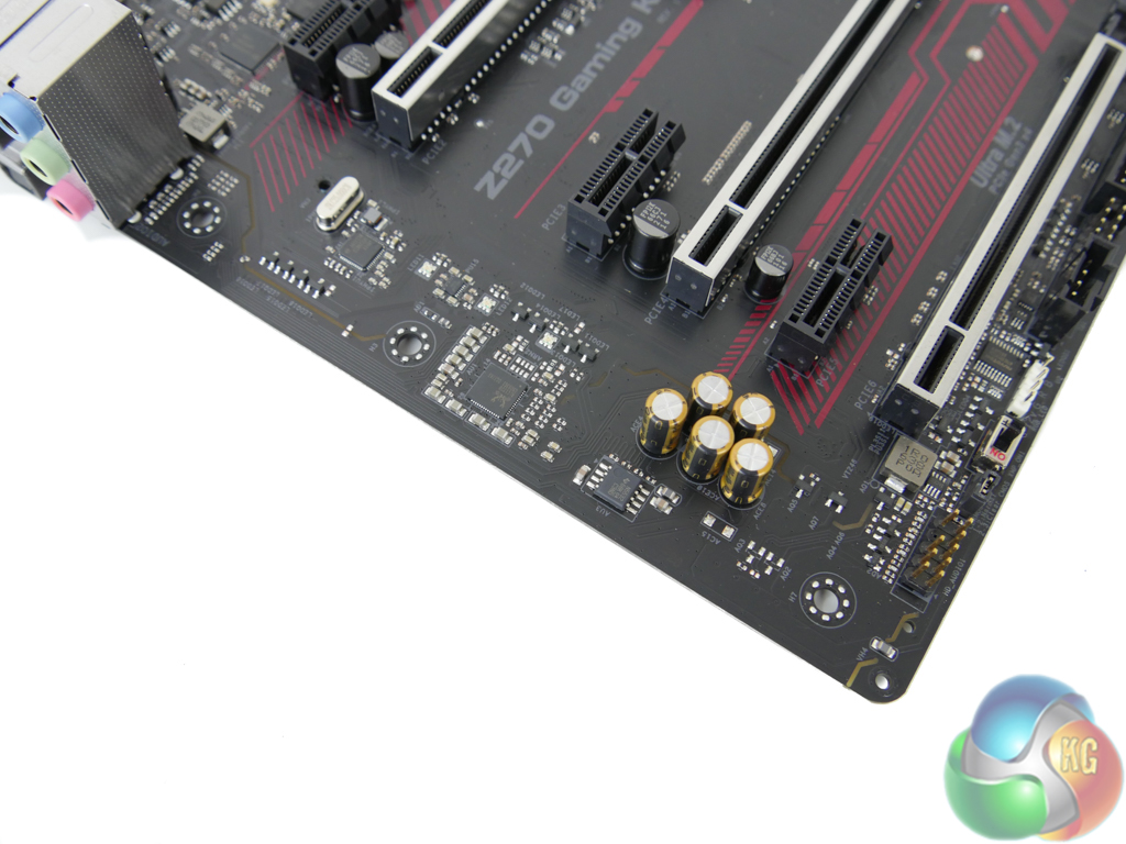
Hidden beneath the RGB LED-equipped plastic shroud is the audio system. The 120dB-rated SNR Realtek ALC1220 codec is used at the heart of the audio system. A Texas Instruments NE5532 amplifier, aided by five 100 microFarad (10V) Nichicon Fine Gold capacitors, boosts the audio signal. Creative Sound Blaster Cinema 3 software-based processing is supported.
The Realtek ALC1220 codec does not use any direct shielding on the PCB but it does send signals along segregated tracks.
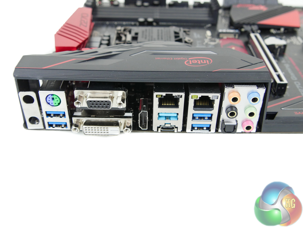
10Gbps USB 3.1 Gen 2 Type-A (light blue) and Type-C ports are powered by ASMedia’s new ASM2142 chipset and an ASM1543 for the Type-C logic. The ASM2142 is a two-lane PCIe chipset that can be fed by up to 16Gbps of total bandwidth when powered by PCIe 3.0 lanes from the Z270 chipset. Importantly, this allows a pair of connected USB 3.1 Gen 2 devices to operate at effectively full speed, rather than 8Gbps of total bandwidth between them, as was the case with the ASM1142 predecessor commonly used for Z170 and X99 motherboards. This helps to reduce the bandwidth and performance advantage that Intel’s USB 3.1 Gen 2 chipsets provided motherboards.
Two pairs of chipset-fed 5Gbps USB 3.0 ports are found along with a PS/2 keyboard/mouse combo port. Single-link DVI-D, HDMI 1.4, and VGA (provided by Realtek RTD2168) video outputs are provided. A triple monitor configuration is supported but the lack of dual-link DVI, HDMI 2.0, or (most importantly) DisplayPort is very disappointing and limits capability with higher-than-1080 resolution displays at 60Hz.
Dual GbE NICs are provided by Intel I219V and I211AT chipsets which are capable of being teamed for a 2Gbps pipe. Disappointingly, teaming is not supported in Windows 10 due to an issue with the OS and Intel driver.
I am not impressed by ASRock’s rear IO decisions. Although space is at a premium, additional USB ports and a DisplayPort connector are glaring omissions; 5 Type-A USB ports will be used quickly and no 4K60-capable display output is disappointing.
A total of five 4-pin fan headers are positioned around the motherboard. Two of these headers are given CPU duties, the second of which doubles as a water pump header that can run at a continuous 100% without PWM interference.
Distribution of the remaining three 4-pin chassis fan headers is good; one is near the rear IO location, with the others residing along the board’s bottom edge and near the 24-pin.
Nuvoton’s NCT6791D chipset manages fan control and system monitoring.
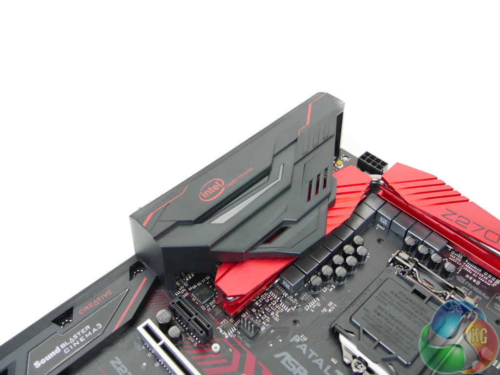
ASRock uses stylish but functional heatsinks for the VRM and chipset. The plastic rear IO cover also houses an RGB LED that can be adjusted via the UEFI and OS software.
Be sure to check out our sponsors store EKWB here
