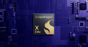

As is convention for its Fatal1ty series of products, ASRock finishes the Z97X Killer in a red and black colour scheme. Compared to previous generation Fatal1ty motherboards, the red used on the Z97X Killer is far brighter than before. The in-your-face approach can take some getting used to, although after a period of time I personally took a liking to the bold colour scheme.
I am pleased to report that ASRock is using a matte black PCB for its Z97X Killer, not the cheap brown alternative that was extensively used on its previous generation of motherboards. For the additional cost, the upgrade to an elegant matte black PCB is well worth it, as gamers and enthusiasts have made clear on a number of occasions.
The only major divergences from the red and black colour scheme are the gold audio capacitors and the white slot latches. Many people like the contrast of white latches on black and red slots, while others may prefer a consistent colour.
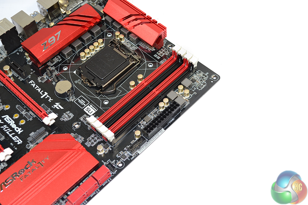
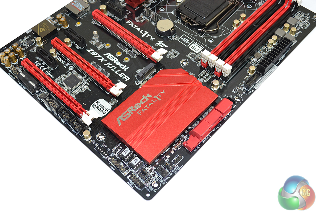
Up to 32GB of DDR3 memory can be installed in four DIMM slots. ASRock states support for 3200MHz+ memory speeds, and the BIOS features 4000MHz dividers, although the maximum frequency is heavily tied to a CPU's IMC.
Sat next to the 24-pin connector is an outwards-facing USB 3.0 header. MSI has treated us with its right-angled approach but ASRock is opting for the more conventional upwards-facing installation that makes cable management more difficult.

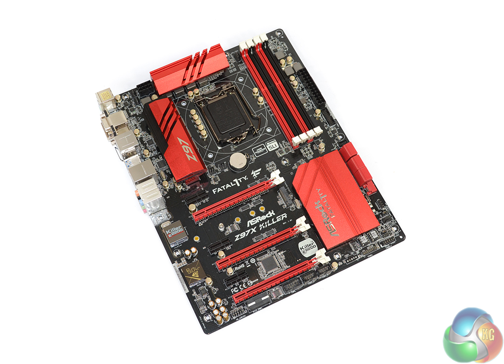
A pair of bright red heatsinks cool MOSFETs that form part of the Z97X Killer motherboard's 8-phase power delivery system.
Under ASRock's Super Alloy branding, the power delivery system comprises Texas Instruments' NexFET MOSFETs for memory, dual-stack MOSFETs for the CPU, platinum capacitors rated for a service life of 12,000 hours at 105°C, and alloy chokes. The components (namely the MOSFETs) are cooled by an ‘XXL' heatsink design, although we don't see anything extra, extra large about the aluminium alloy coolers.

One 4-pin CPU fan connector is positioned above the DIMM slots while the other is accompanied by a 3-pin powered header near the IO shield. We would have liked to see the headers positioned closer together, although we must compliment ASRock for including a 3-pin powered connection which is convenient for pump units.
ASRock places the 8-pin power connector in an ideal location for routing a cable up behind the motherboard tray.
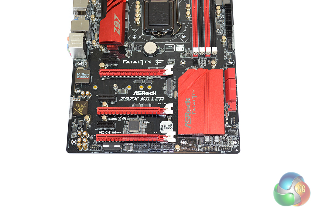
Three full-length PCIe 3.0 slots are fed by the LGA1150 CPU's lanes. For common CPU's such as the 4670K and 4770K, the slots will receive sixteen PCIe 3.0 lanes between them. Lanes can be split as x16/x0/x0, x8/x8/x0, or x8/x4/x4. The lane allocation indicates support for three-card CrossFire, although only two-card SLI is supported by virtue of x8 link requirements.
Installing a PCIe device such as an x4 SSD in the lower full-length PCIe slot will take bandwidth from the connections above it and force SLI to be disabled. Given the support for M.2 and SATA Express, this isn't as much of an issue as it was with the 8-series chipset.
A further three chipset-fed PCIe 2.0 x1 slots fill out the expansion area. Spacing of the slots is as good as it gets for a gaming motherboard of this calibre. Dual-width cards can be given a breathing gap in the upper connectors, or three-slot boards can be installed without hassle.
Sat beneath the primary PCIe x16 slot is the board's 10Gbps M.2 connector. Access to the connector will dictate the removal of a graphics card, which will be a frustrating procedure to some users. On the other hand, having a large VGA board sat above an M.2 SSD will completely hide the drive's (typically) ugly green or blue PCB. The latter point may be of more worth to many appearance-conscious gamers.
The reason behind ASRock's positioning is to allow the M.2 slot to support drives up to 110mm in length. PCIe and SATA devices are supported in the M.2 slot; the bandwidth is allocated via the chipset's PCIe or SATA links.
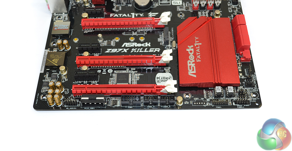
The standard affair of front panel headers is found on the Z97X Killer – audio to the left and front panel connections to the right. A downwards-facing molex connector can be used to provide additional power to multi-GPU configurations.
Dual socketed BIOS chips are used by the Z97X Killer, giving users redundancy and the option to switch out chips in the event of a failure.
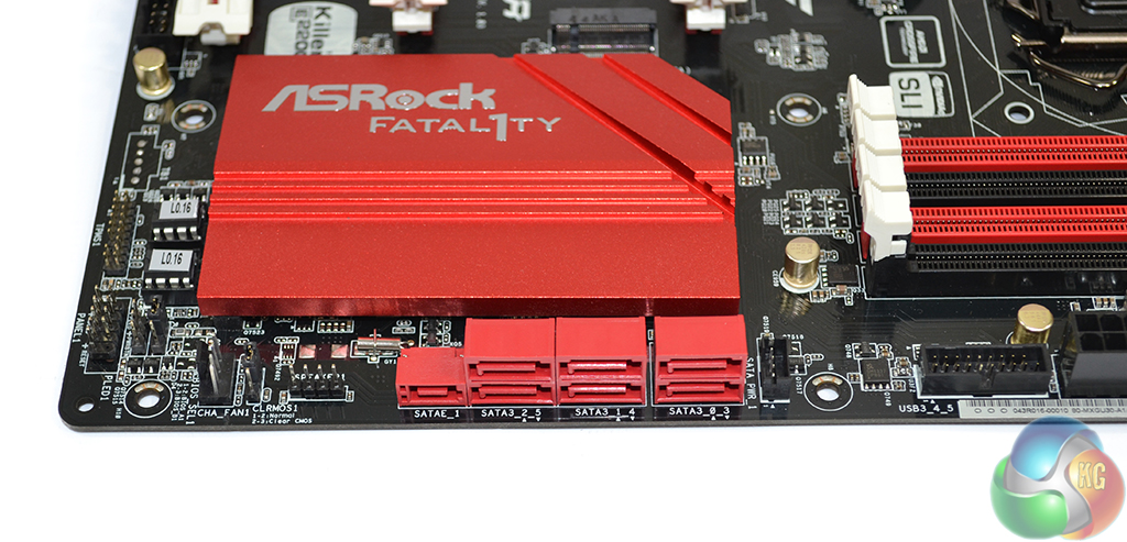
Six SATA 6Gbps ports are provided, all of which are fed by the Z97 chipset. ASRock also provides a SATA Express connector which is formed by using two of the chipset SATA ports and an additional bandwidth-carrying link.
Bandwidth for the SATA Express connection is shared with the aforementioned pair of SATA 6Gbps ports and the M.2 slot (only one of the three sets can be used at any one time). We like the inclusion of M.2 and SATA Express connections as it allows users to choose to interface that best suits their needs when both become more predominant.
To the right of the SATA banks is ASRock's HDD Saver header. Connecting a drive to the port allows its operating state to be controlled via the OS. For example, a user can choose to shut down their drive while their system is in operation, for reasons such as security, noise, and longevity. Up to two SATA devices can be controlled via the one header.
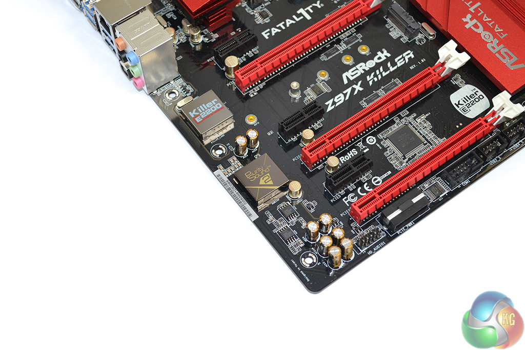
Networking capacity is provided by a Killer E2200 series NIC. Killer's E2200 devices have proven popular on gaming motherboards for their low-ping performance and software tools, both of which are useful to gamers. A metal shield is used to prevent electromagnetic interference (EMI).
ASRock's Purity Sound 2 audio system is powered by a Realtek ALC1150 codec, hidden beneath an EMI shield. Nichicon fine gold capacitors are used to assist signals that are sent along a discrete PCB pathway. A pair of Texas Instruments NE5532 amplifiers is used to drive headphones with impedance levels of up to 600 Ohms and to amplify audio signals.
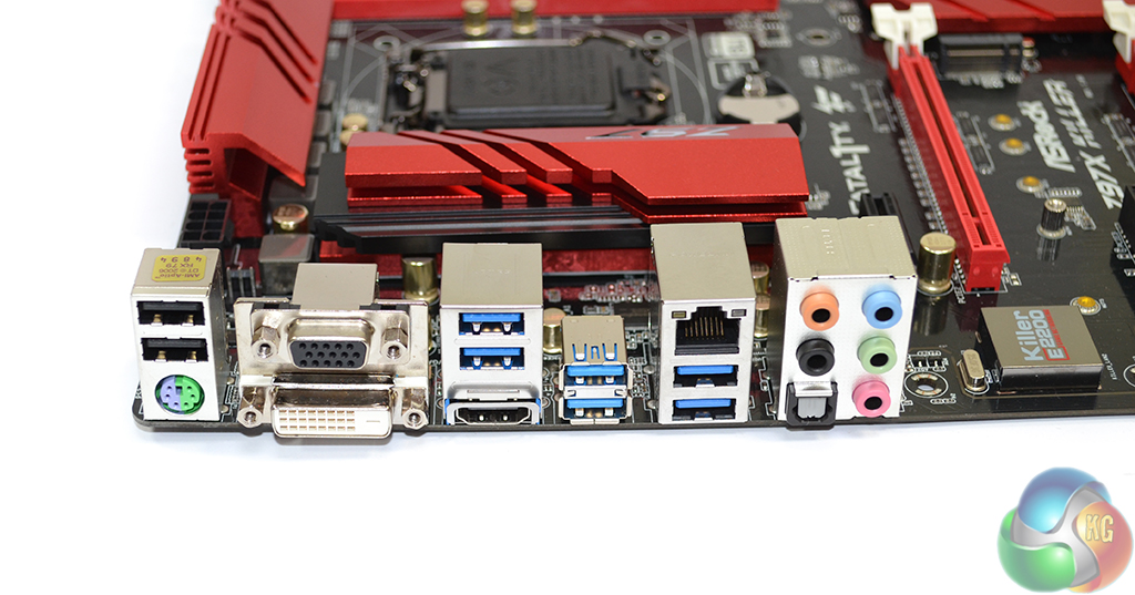
Six USB 3.0 ports are found on the rear panel, two of which are provided by an ASMedia ASM1042AE host controller. The Fatal1ty mouse port and ASRock's Key Master software can be used to tweak the operation of a mouse. PS/2 is provided for gamers still rocking their older mechanical keyboards.
Switched via an ASMedia 1442K controller, the three video connections provide support for high resolution monitors via the onboard GPU.
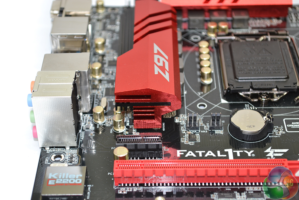
ASRock's bright red heatsinks use an aluminium alloy material to cool the components beneath them. As is typically the case for mainstream-chipset motherboards that aren't designed for extreme overclocking, the heatsinks serve as much of an aesthetic purpose as they do a cooling one.
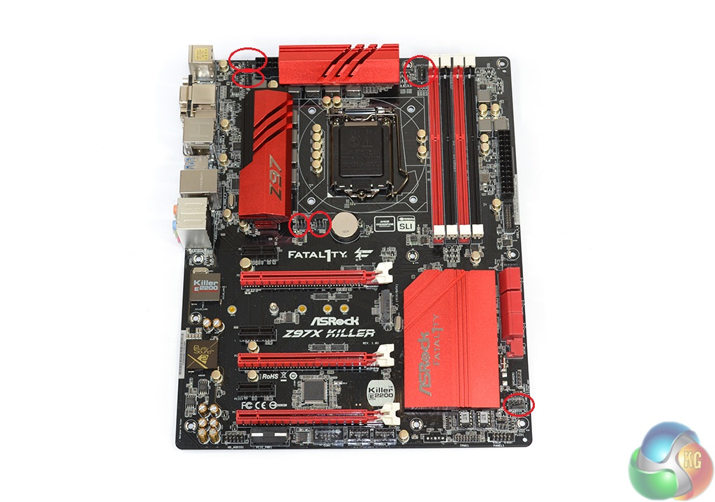
Controlled by a Nuvoton NCT6791D Super IO chip, a total of six fan headers are found on the Z97X Killer. Two of the headers are powered via the CPU PWM channel (one of which is 3-pin), a further three operate chassis fan duties (one 4-pin, two 3-pin), and a 3-pin connector is used as a powered header.
Distribution of the fan headers is very good. ASRock positions five within reach of the CPU socket, all of which can be accessed by rear or roof chassis fans. The final header is found near the motherboard's bottom edge, making it suited to side panel fan duties.
Being particularly critical, shifting one of the mid-board headers nearer the SATA slots would have been convenient for cable management duties.