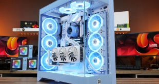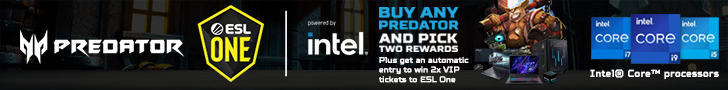

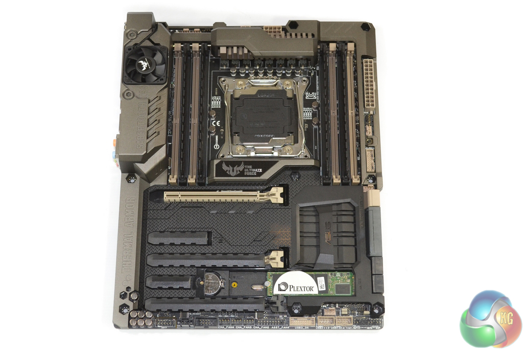
Evidently the most striking feature of Asus' TUF Sabertooth X99 motherboard is its full-cover Thermal Armor. The plastic shroud covers a vast proportion of the motherboard's PCB in order to provide protection from elements such as dust, as well as thermal segregation from expansion cards.
Asus does indeed stick to the TUF series' defining black, green(ish), and beige colour scheme, however certain elements are far more difficult to detect due to Thermal Armor. The Sabertooth X99 conforms to the standard ATX form factor.
All of the critical system connectors are accessible with the plastic shroud maintained in position. The one exception is the M.2 connector which demands the removal of a plastic covering in order to obtain access.
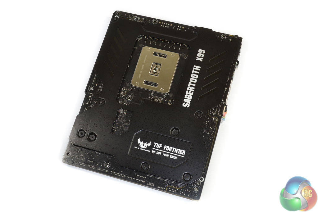
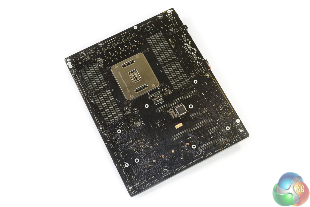
The rear-mounted TUF Fortifier is, put simply, a formed sheet of metal. Its purpose is to provide structural integrity for the motherboard, which it most certainly does. A secondary application of the metal is to cool rear-mounted power components at the one place where contact to the PCB is made; non-conductive spacers maintain clearance with the PCB elsewhere.
Don't bother trying to route cables between your motherboard and case stand-offs – TUF Fortifier engulfs the space that is provided. The metal reinforcement also adds a noticeable weight to the motherboard, although this is highly welcomed in order to avoid PCB flexing issues with heavy graphics cards or CPU coolers.
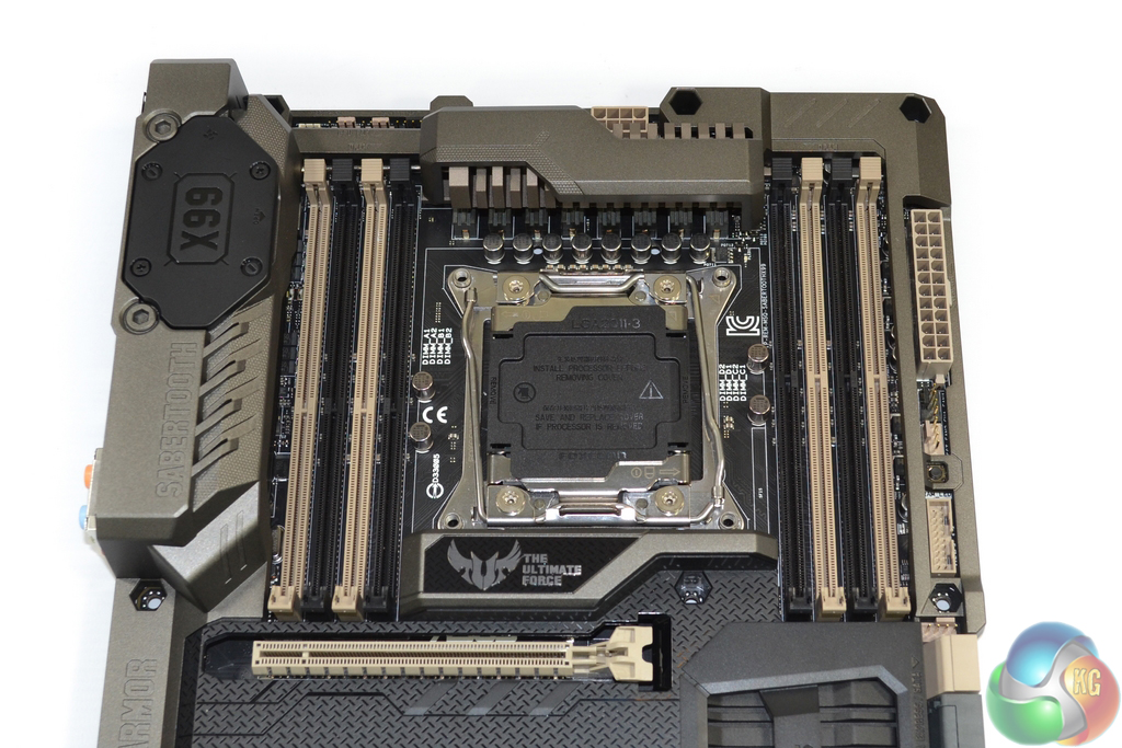
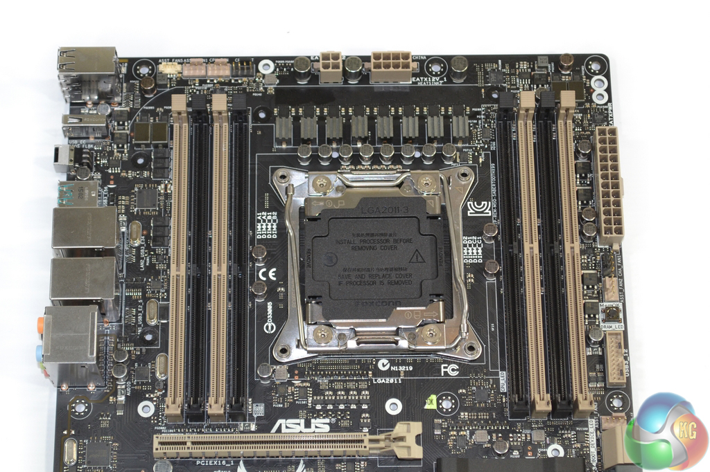
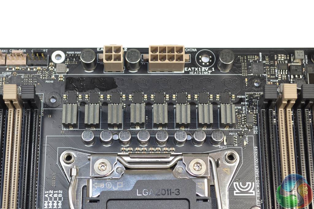
Asus outfits the Sabertooth X99 with the company's ingenious OC Socket. The implementation leverages extra pins that typically go unused in order to provide greater flexibility for CPU-related voltage tweaking. Settings related to CPU Cache voltages and frequencies typically show the greatest benefit from OC Socket.
A well-cooled eight-phase power delivery system feeds the LGA 2011-3 CPU socket, the details of which we will explore later in our analysis.
Eight DIMM slots provide support for up to 64GB of Non-ECC DDR4 memory. Asus states support for memory speeds of up to 2400MHz, although higher frequencies can be achieved (as we will prove later in the review). Single-latched DIMM slots are used to eliminate interference with a graphics card.
It is worth pointing out that clearance for large, low-hanging air coolers will cause headaches. The high-rise VRM covering and TUF badge located in the ‘Northbridge' spot, will cause clearance issues for air coolers. Even the lower-mounted screws for our Corsair H100i's pump/waterblock unit were difficult to tighten due to the space constraints.
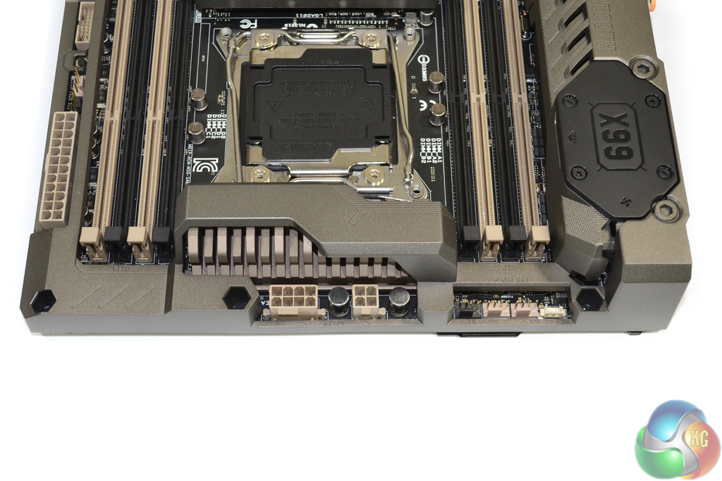
The CPU is fed power through 8-pin and 4-pin connectors. The 8-pin can be used alone if your power supply only has one CPU power connector.
While I do not believe that the extra power connector is required for Haswell-E until particularly high voltages are being fed, balancing current through two routes may aid component longevity.
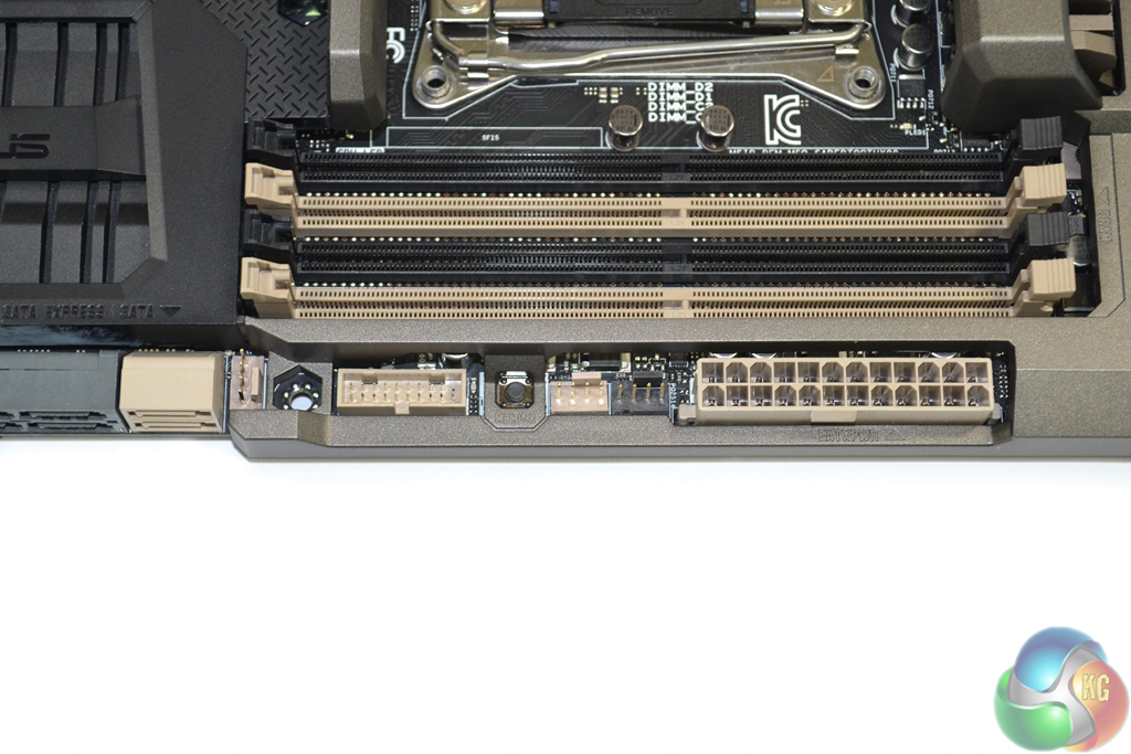
Asus positions the 24-pin power connector further towards the motherboard's upper edge than is common. While this is not an issue, it is worth highlighting for cable management routing purposes.
A cluster of 4-pin fan headers is joined by the ever-convenient MemOK button and one of the two outwards-facing USB 3.0 headers – the ports for which run directly from the X99 chipset.
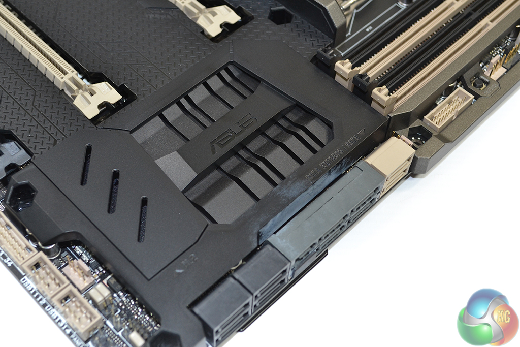
All ten of the motherboard's SATA 6Gbps ports stem from the X99 chipset. Ports 0-5 (the ones starting from the right) should be used for RAID configurations, while the remaining four are suited for basic storage purposes.
Two of the SATA 6Gbps connections double-up to form the 10Gbps SATA-Express connector. The SATA-Express connection can be used at all times as it does not share bandwidth with the M.2 slot.
A smart-looking, black heatsink cools the X99 chipset.
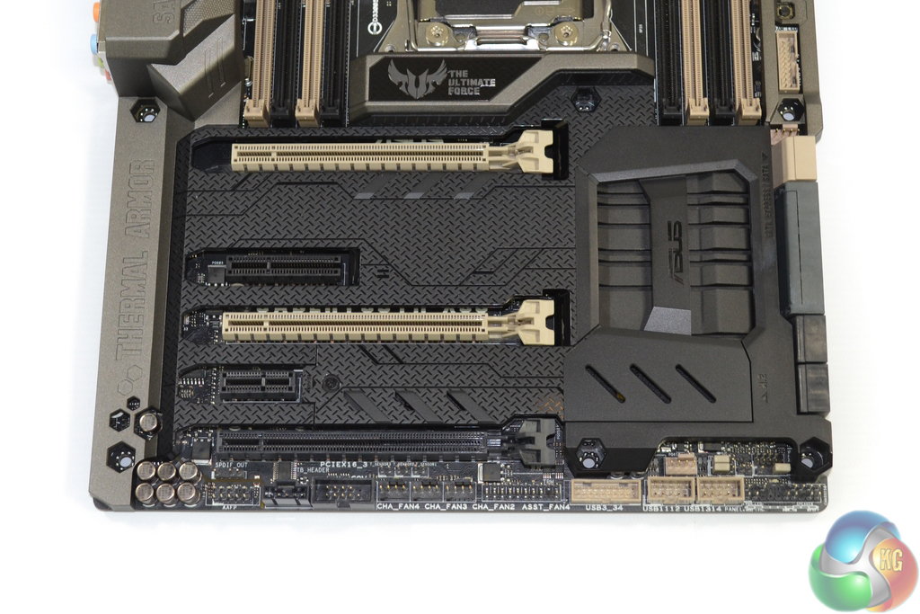
3-card SLI is supported on a 40-lane CPU only. With a 40-lane chip, lane allocation of the three full-length PCIe slots is x16/x16/x8. That third slot shares its bandwidth with the PCIe 3.0 x4 M.2 connector, so only one of the choices can be used at any time.
Put simply, you only get 3-card SLI with a 40-lane chip, and even then you can only use it if you sacrifice the M.2 slot (which does not support a SATA connection as a backup). Clearly, 2-card solutions are Asus' aim, so the one-slot cooling gap between a pair of boards is good.
Using a 28-lane chip results in a PCIe lane allocation of x16/x8/x4, which is usable for 3-card CrossFire, but not 3-way SLI. As already pointed out, using an M.2 SSD forces the sacrifice of the lowest slot's connection.
Asus could have tweaked this system with relative ease to make 3-card SLI/CrossFire plus a PCIe 3.0 x4 M.2 SSD feasible on both 40- and 28-lane chips. Enough of the competing solutions do exactly that. While I understand that the demographic for a trio of graphics cards is small, I do not feel that a high-end X99 motherboard should be the limiting factor.
The shorter two PCIe slots operate with a combined total of two PCIe 2.0 lanes from the X99 chipset. Despite the second PCIe slot's x4-length, the connection is actually wired for up to two lanes, making it specifically chosen for the likes of PCIe SSDs or USB 3.1 expansion cards.
Using the dedicated PCIe 2.0 x1 slot steals a lane from the x4-length connector and forces both to run with one lane of connectivity each.
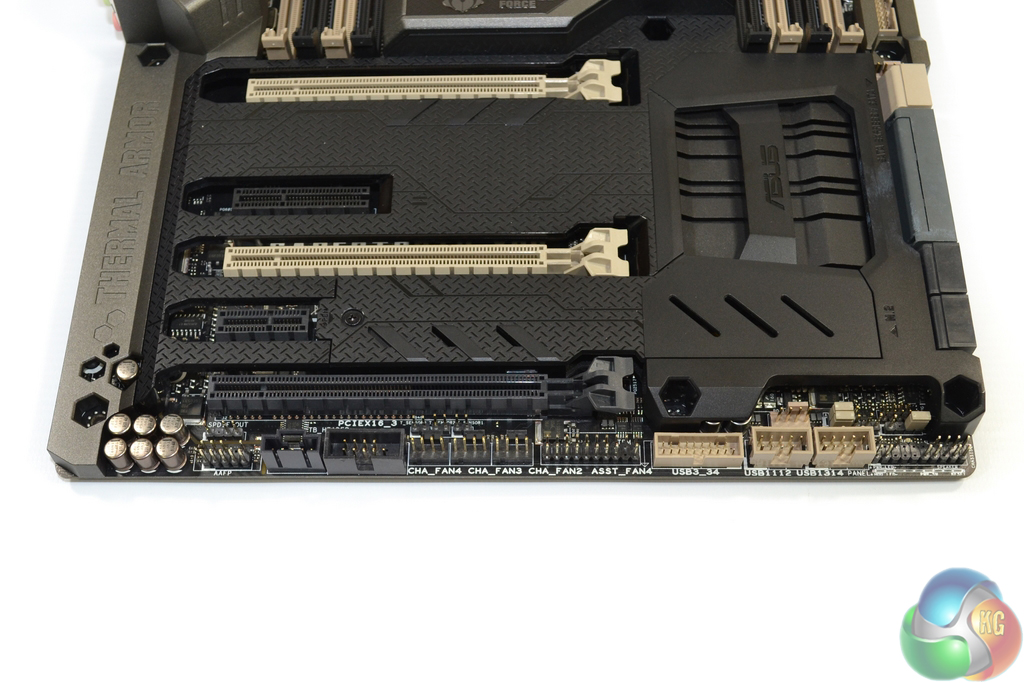
Front panel connections are the typical affair – chassis headers to the right and the audio link to the left. Two USB 2.0 headers, an additional X99-fed USB 3.0 header, and the Thunderbolt link are also situated on the board's bottom edge.
Legacy COM and TPM headers are joined by four 4-pin fan connections. Just above the bank of three, black-coloured fan headers is the trio of thermistor connections.
A graphics card mounted in the bottom slot will block all of these connectors, although Asus is not particularly pushing about this board's 3-way SLI/CrossFire application.
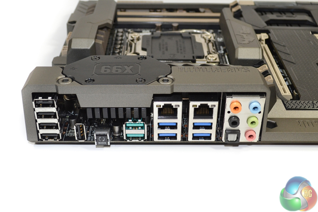
Five USB 2.0 ports are found on the rear IO, one of which can be used for BIOS Flashback and TUF Detective app duties. Asus' block diagram suggests that one of the rear-mounted USB 3.0 ports runs directly from the X99 chipset, while the other three are provided via an ASMedia ASM1074 hub controller.
ASMedia's ASM1142 PCIe 2.0 x2 host controller is used to provide a pair of 10Gbps USB 3.1 Type-A ports. We examined Asus' USB 3.1 implementation with a pair of RAID 0 SSDs over here.
Intel's I218-V chipset is used for one of the GbE NICs, while a Realtek 8111GR solution powers the other. The audio ports are fed by a system which comprises Realtek's ALC1150 codec and a Texas Instruments RC4580 operational amplifier (marked R4580i).
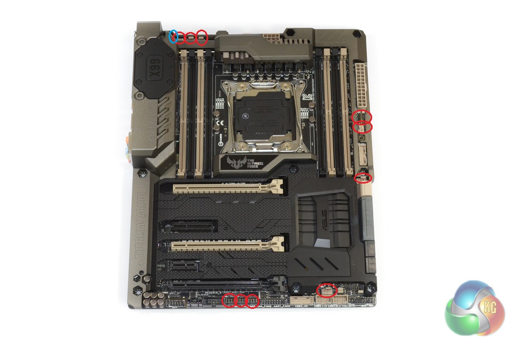
Ten 4-pin fan headers are distributed around the motherboard, with an additional laptop-style connection powering the chipset fan. Distribution of the headers is very good, although I do not understand why Asus did not provide a connection in the typical location for serving a rear chassis fan.
Every one of the PWM-capable fan headers can be controlled via the UEFI or Thermal Radar 2 OS-based software. That is highly impressive and may save water-cooling users the expense of a dedicated fan controller.
The TUF ICe and Nuvoton NCT6791D-A chipsets are to thank for such extensive fan control, while additional TPU components help form the motherboard's extensive monitoring system.
Removing its dedicated cover gives access to the 40mm fan mount. The ~6300rpm fan is used to blow cool air over an extended section of the MOSFET heatsink. The fan becomes audible above around 4000rpm. I set it to only switch on when the CPU is hot, by which point my Corsair H100i fans' noise output will dominate acoustic emissions.
Incidental airflow is also fed beneath the Thermal Armor, although this may actually cause an increase to PCB temperature if the MOSFETs are running hot enough to warm their coolant air above the native PCB temperature.
The ugly green PCB of an M.2 SSD can be hidden by the section's dedicated covering. Drive lengths of 40, 60, 80, and 110 mm are supported. Only PCIe-fed M.2 SSDs can be used due to the connector's PCIe 3.0 lanes deriving directly from the CPU. M.2 SATA SSDs are not supported.
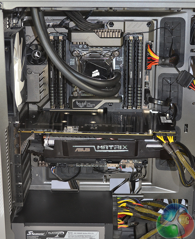
The grey-ish sections of Thermal Armor are a good match for the gunmetal colouring of NZXT's Phantom 630 chassis. The motherboard's dark appearance makes it a good match for black components, such as memory.
Thermal Armor and Power Delivery System
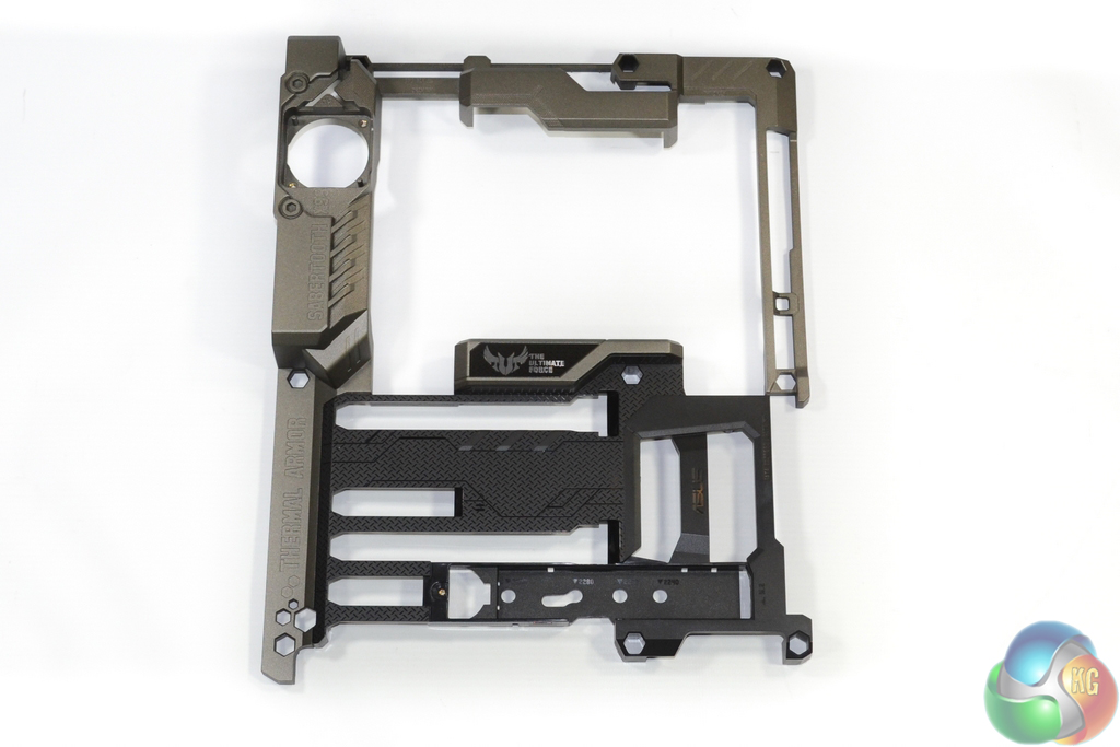
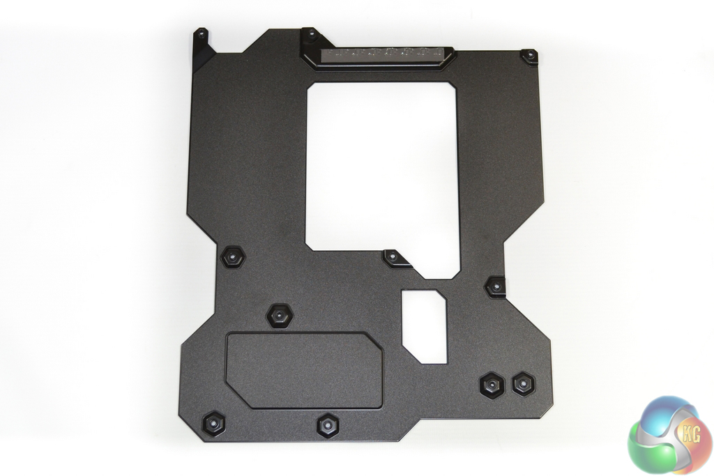
Removing Thermal Armor and TUF Fortifier is a simple process – just detach the relevant screws.
It can be seen that Thermal Armor is no more than a shaped plastic shroud, although that is not a negative point with one of its main goals being unique appearance. TUF Fortifier makes direct contact, via a thermal strip, with rear-mounted CPU power delivery components in order to provide cooling.
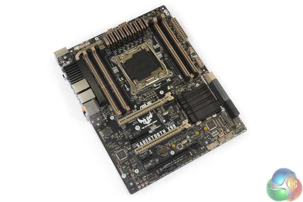
With the shroud removed, the old-style beige colouring is far more noticeable for the board's slot connectors.
Asus has placed importance on the motherboard appearance without Thermal Armor attached. Users who decide to water-cool the MOSFETs (if a block becomes available) are likely to be forced to remove the plastic shroud entirely.
No power delivery components with noteworthy heat output are located near the rear IO area. This proves that the heatsink's extended section that runs parallel to the rear IO is simply used for additional heat-dissipating surface area.
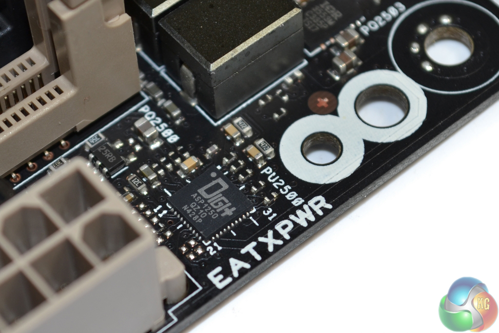
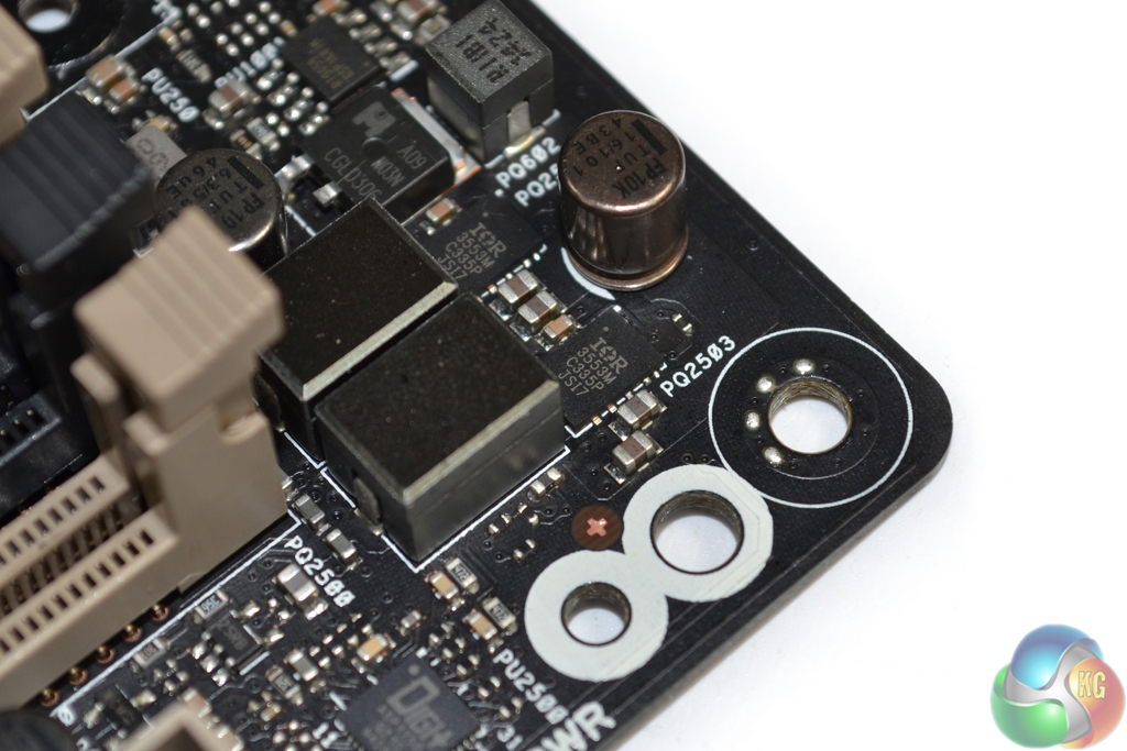
The eight-phase CPU power delivery system includes TUF Chokes (marked R15A 1501), 10K-rated Ti-caps, and MOSFETs which are certified by the military-grade testing procedure.
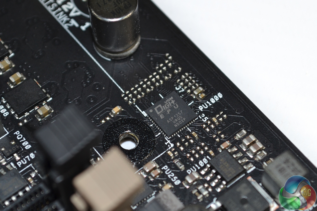
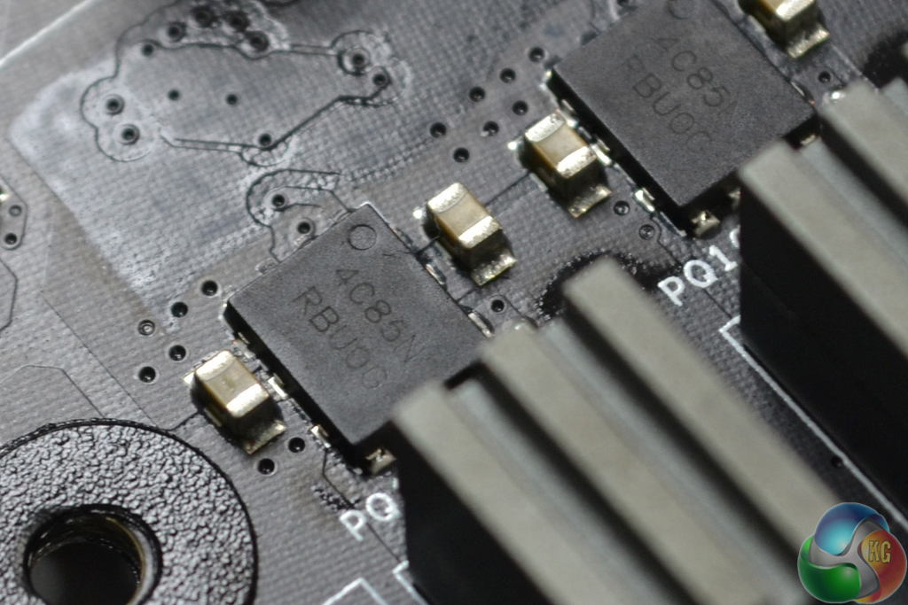
A Digi+ ASP1257 controller manages the CPU's power delivery system. I must admit that I am surprised to see Asus equipping the Sabertooth X99 with ON Semiconductors' NTMFD4C85N (marked 4C85N) dual N-channel MOSFETs.
These are the same MOSFETs that we found on the company's lower-priced X99-A motherboard. They are not regarded to be on the same level as the likes of International Rectifiers' IR3550 PowIRStage MOSFETs used on the Asus X99-Deluxe and Rampage V Extreme.
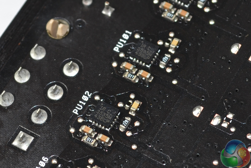
Directly behind the front-mounted MOSFETs are eight International Rectifiers IR3535M floating N-channel MOSFET drivers.
These are the components which are actively cooled by the TUF Fortifier and its accompanying thermal pad.
One Digi+ ASP1250 controller manages each of the 4-DIMM banks (two in total). Each DIMM bank is also powered by two International Rectifiers IR3553M MOSFETs, two chokes (marked R30PS), a set of capacitors (flat-pack for the left DIMM bank), and one GSTek GS9238 buck converter.
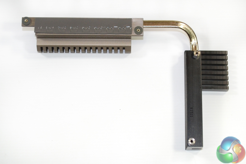
While only one fin array of the VRM heatsink makes direct contact with the MOSFETs, a heatpipe connects the second array. That heatpipe is critical for transferring heat from the direct-contact fin array to the black block of metal that is cooled by the fan.