

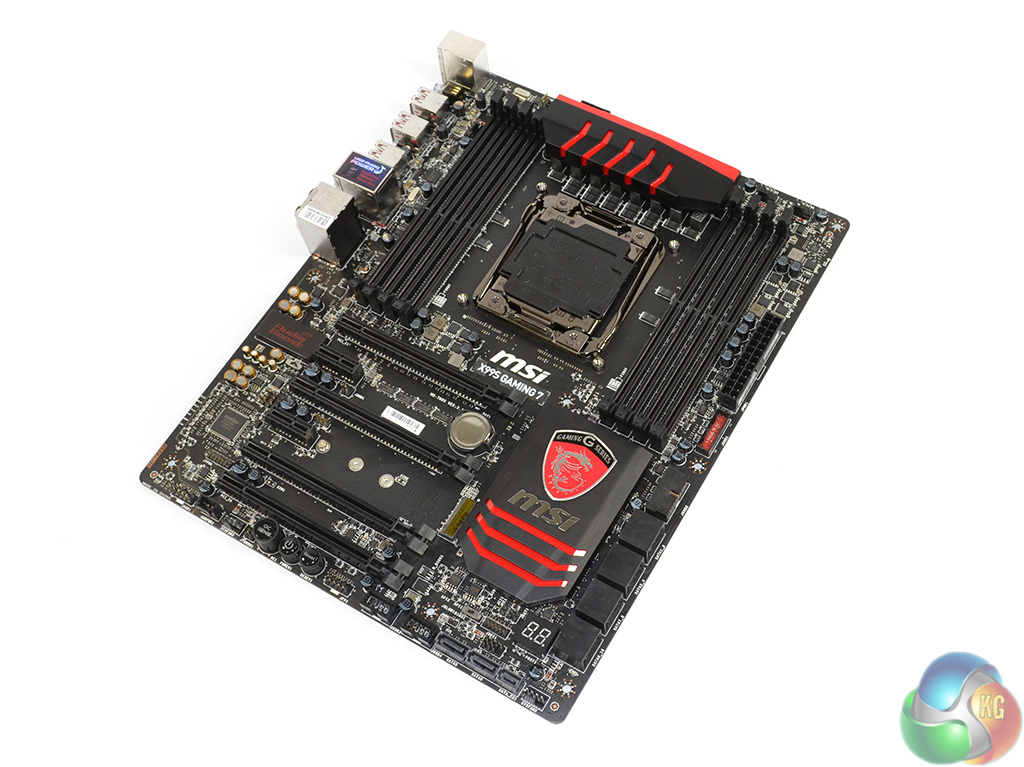
The company's tried-and-tested red-and-black colour scheme is used for the MSI X99S Gaming 7. MSI pretty much cracked the styling code with its Z87 and Z97 Gaming series motherboards, so the X99 part builds on that well-received appearance.
Small but well-positioned hints of red contrast the dark black PCB to create an eye-catching theme. Such is the component-heavy nature of MSI's board, the white writing and silver traces of solder accommodate large PCB sections and dampen the X99S Gaming 7's appearance slightly. There's very little that can be done to contest that reduced attractiveness issue.
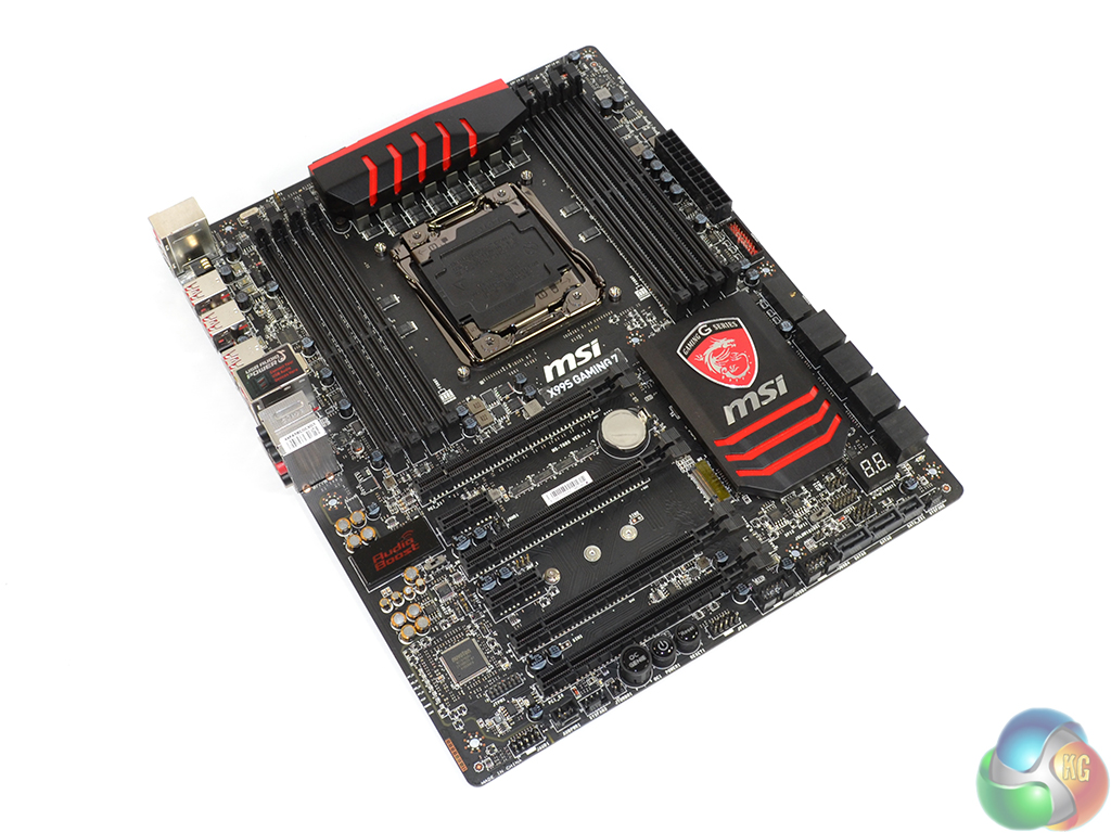
As for colour-coordination, red or black memory kits are the ideal compliments for MSI's styling. Equally fitting from a styling perspective would be one (or multiple) of MSI's new Twin Frozr V-cooled graphics cards.
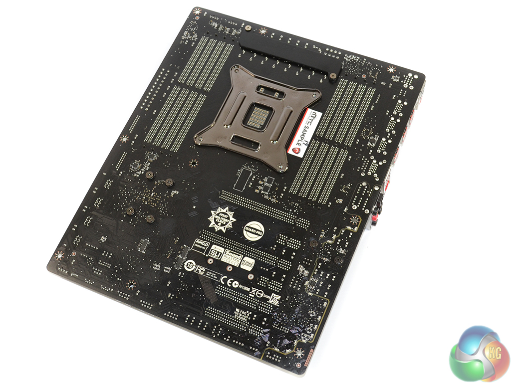
A small strip heatsink cools the MOSFET rear connection points, while a sturdy backplate provides structural rigidity for times when heavy CPU coolers are installed.
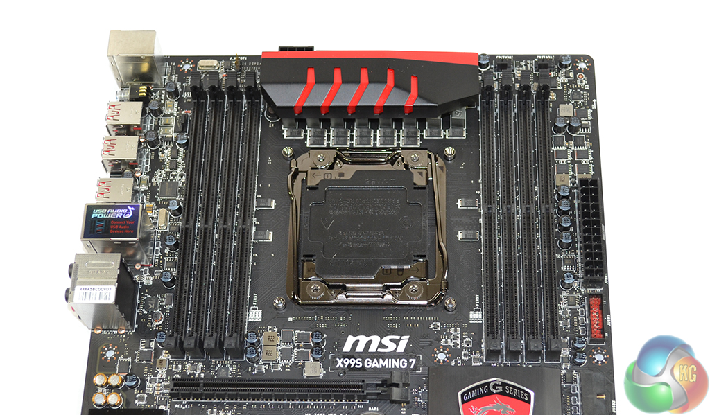
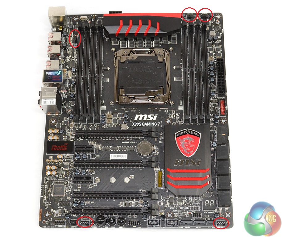
MSI’s somewhat bare LGA 2011-v3 CPU socket is sandwiched between two DIMM banks. The reason for the socket’s bare appearance is because, as previously pointed out, MSI incorporates the pre-mounted CPU cooler backplate behind the motherboard rather than surrounding the socket. This keeps clutter to a minimum around the socket area.
Up to 64GB (using current – 8GB – modules) of DDR4 memory can be installed in the motherboard's eight slots. MSI quotes maximum frequency support for 3333MHz DDR4 memory via overclocking, although the real-world limit will be tied to BIOS implementations and a CPU's Integrated Memory Controller (IMC) strength.
Space between the CPU socket and VRM heatsink is tight and has the potential to cause interference with wide, low-hanging CPU coolers. Thankfully, heatsinks touching up against the PCB of a graphics card installed in the top slot is not going to be an issue with the X99S Gaming 7 – its first slot actually sits in the board's second position.

An Intersil ISL6388 6-phase PWM controller manages the CPU power phases, while two Powervation PV3203 controllers are in charge of the memory and its accompanying system voltages. While there are eight physical phases near the CPU, with an additional one seeming to hide behind the MOSFET heatsink, the controller usage implies that six phases are feeding the processor while the remaining provide for memory-related voltages.
All of the electronic components for CPU power delivery are positioned above the CPU socket. This minimises the length of path that current has to flow on and can therefore improve power delivery.
The power delivery system comprises MSI's Military Class 4 electronic components. Hi-c capacitors, with an efficiency rating of up to 93%, work with Super Ferrite Chokes (SFC) and aluminium-core Dark capacitors to deliver electrical power.
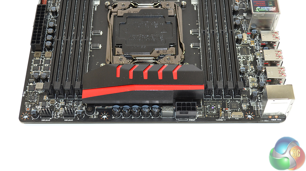
Two 4-pin fan headers and the 8-pin power connector are found along the motherboard's upper edge. MSI allocates one of the headers for CPU fan duties, while the other runs from a SYS_FAN control channel.

Sat next to the 24-pin power connector is an outwards-facing USB 3.0 header. A few centimetres down from that is an additional header in the right-angled orientation.
The JUSB1 header supports MSI's Super Charge application. Both USB 3.0 headers' ports derive from the X99 chipset.

Despite featuring enough slots (and CPU links with a 40-lane chip) to feed 4-way setups, MSI does not add the necessary controller to enable any more than 3-way SLI or CrossFire. Thinking sensibly though, up to a trio of graphics cards working together is going to suffice for almost all users buying a £200 motherboard.
According to MSI's manual, PCIe connections for a 40-lane CPU are allocated as (from top to bottom full-length PCIe slots): x16 for a single card, x16/x16 for two cards, and x16/x16/x0/x8 for three cards. The one- and two-card configurations support PCIe 3.0 x4 for the M.2 connector, but three graphics cards will drop that link to PCIe 2.0 x2. That's a big bandwidth hit on the storage front; we would have preferred MSI to drop one of the three cards to x8 link speed and maintain the PCIe 3.0 x4 connection for a high-speed M.2 drive.
Using a 28-lane chip is a little different. Obviously a single card runs at x16, but two operate via sixteen and eight PCIe 3.0 links, respectively, and three cards all get eight PCIe lanes each. PCIe 3.0 x4 for the M.2 connector is preserved throughout.
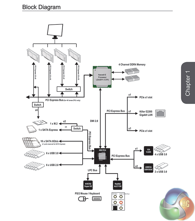
Now here's where the fun and games start. That third full-length PCIe slot that shares sixteen lanes with the first connector can, despite MSI's advice, be used with a 40-lane chip. Sticking graphics cards in the first, second, and third full-length slots should, in theory, result in an x8/x16/x8 + PCIe 3.0 x4 configuration. MSI's documentation doesn't highlight it, but we see no reason as to why that wouldn't be supported (as backed up by the above block diagram).
Expansion slot layout is good. I would have preferred MSI to use the first and third full-length PCIe slots for two x16 graphics cards, rather than the first and second. Back-to-back boards always present a cooling headache. 3-way SLI or CrossFire with a 40-lane CPU sees a potential cooling gap left between the second and third cards (assuming dual-slot coolers), but this also makes the SATA Express connection impossible to use due to its large connector.
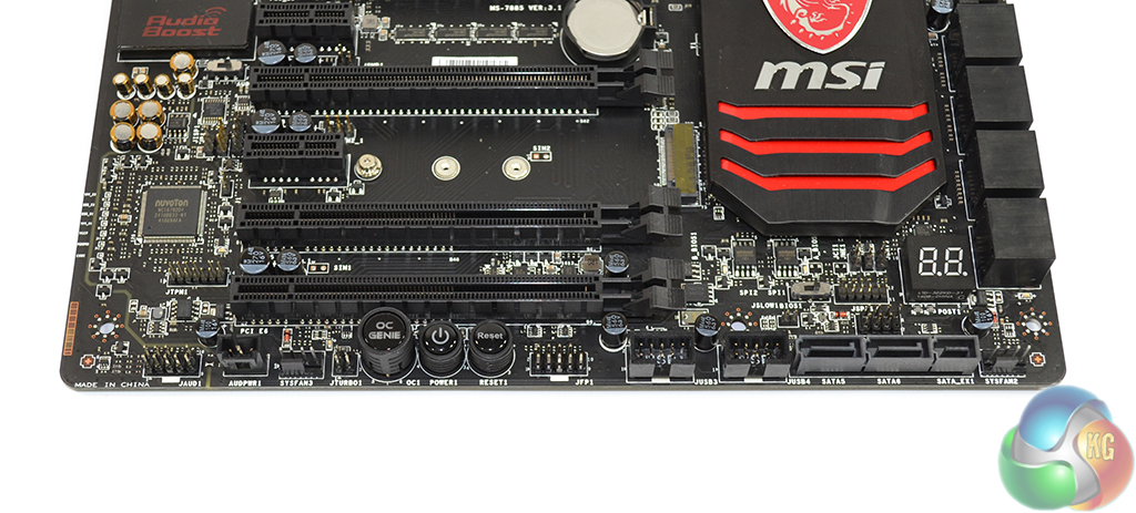
Along the motherboard's bottom edge we find the usual affair of front panel, USB 2.0, and audio headers. MSI also equips the X99S Gaming 7 with onboard power, reset, and OC Genie buttons which are always useful in times of on-the-table troubleshooting. A two-digit LED display is sat above the outwards-facing SATA Express connector, just a few centimetres from the multi-BIOS switch.
As already pointed out, the 10Gbps SATA Express connector is going to be rendered inaccessible as soon as a long graphics cards is installed in either of the lower two PCIe slots. MSI should have changed its orientation or positioning to avoid such inconveniences.
We also want to point out the header that provides MSI's Audio Boost 2 system with its discrete source of power. The supplied molex power adapter connects to the header that is positioned just right of the front panel audio connection.
MSI implements a ‘Turbo M.2' connector that runs off four PCIe 3.0 lanes from the CPU to provide up to 32Gbps of data transfer speed. Taking its lanes from the CPU means that an M.2 device can be used at the same time as a SATA Express drive. If all of the CPU's PCIe 3.0 lanes are being used by expansion cards, the M.2 connector can steal the SATA Express port's two chipset-fed PCIe 2.0 lanes to provide a 10Gbps connection.
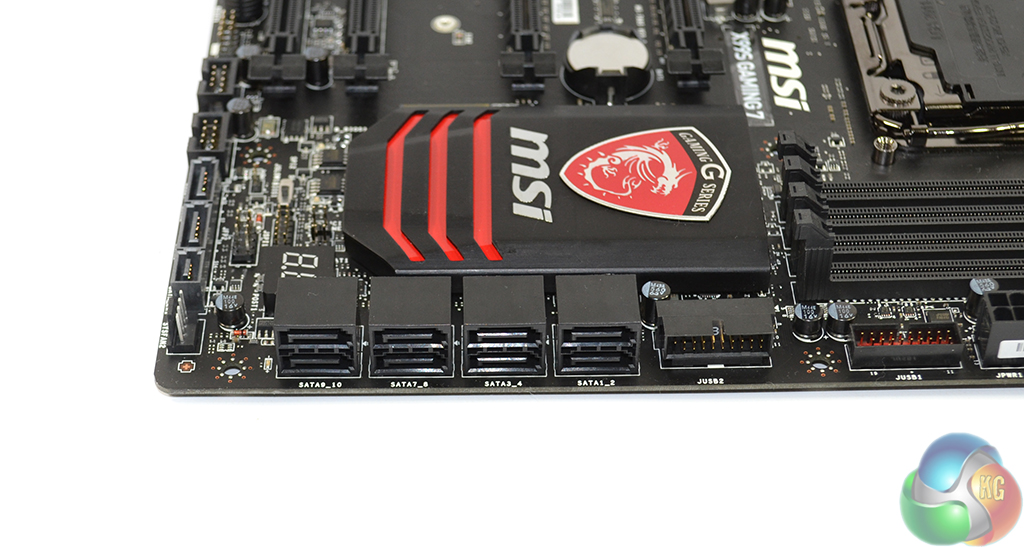
Eight right-angled SATA 6Gbps ports all operate from the X99 chipset. The remaining two connections are bundled together to help form the SATA Express port.
Placing one of the USB 3.0 headers in a right-angled orientation is one of my favourite moves for a motherboard vendor to make. Hiding the cumbersome front panel USB 3.0 cable is a far simpler task when it doesn't stick vertically out of the board.
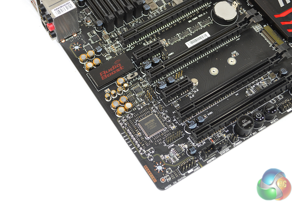
MSI continues to steam ahead with its tried-and-tested Audio Boost 2 system on Gaming series motherboards. The gaming-orientated solution has received positive feedback amongst users.
Based around the Realtek ALC1150 and its 115 dB Signal-to-Noise Ratio (SNR), MSI's Audio Boost 2 system also calls upon Nichicon power-smoothing capacitors and Texas Instruments' OPA1652 amplifier. We know that the TI OPA1652 is perceived as a particularly potent operational amplifier, capable of driving high – up to 600 Ohm – headphones.
Just beneath the branded shield for Realtek's ALC1150 audio codec is the switch to toggle between motherboard-fed current or voltage from the discrete audio power connector. Also worth mentioning is MSI's USB Audio Power delivery system that, the company says, feeds USB-driven headphones and DACs with a stable five volts, rather than fluctuating levels that can derive from traditional solutions.
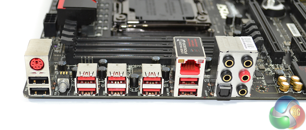
Without the onboard video connections of Z97 boards, USB ports form the vast majority of the X99S Gaming 7's rear IO. The two USB 2.0 ports and accompanying PS/2 connector are part of MSI's Gaming Device Port system. MSI suggests that the ports can help deliver smoother gameplay, although we're sceptical of that claim without a clear-cut way to obtain scientific results.
Eight red-coloured USB 3.0 ports are supplied through a combination of sources. Although it is not listed in MSI's manual which ports operate from which controllers, our empirical testing gives an insight into where the connections derive. Two ports beneath the LAN connector operate from Intel's X99 chipset. The two directly to the left of those are provided by ASMedia's PCIe 2.0 x2-fed ASM1042AE host controller. The remaining four operate from a PCIe x1 VIA VL805 host chipset.
It is important to know how the ports are fed their bandwidth because, as our testing later will show, there are noticeable speed differences between each of the USB 3.0 host controllers.
MSI continues to use Killer's E2205 NIC thanks to its suggested performance benefits in dealing with small and large data packets (gaming and streaming, respectively). Perhaps a bigger factor for MSI's commitment to the Killer NIC is its excellent Network Manager software that dynamically allocates network bandwidth in the preferable (or user-defined) locations.
Completing the rear IO are gold-plated audio connectors, an optical sound output, and the ever-useful clear CMOS button. MSI installs a blue LED in the clear CMOS button to make it easy to locate when shuffling around the rear side of a system.
Five 4-pin fan headers are handled by Nuvoton's excellent NCT6792D+ Super IO chip. The reason we like Nuvoton's chip so much is because, using a Z97 motherboard with onboard voltage reading points, we have tested its voltage readings to be highly accurate when compared to the levels read from a multimeter.
Distribution of the five fan headers is generally good. One of the CPU connectors is found above the right-hand DIMM bank, alongside a system fan header, while the other resides near to the rear IO.
We always recommend placing a fan header to the top-left of the primary expansion slot, allowing it to cater for a rear chassis fan with the minimum length of cable laying about. MSI instead takes this header and places it along the motherboard's bottom-edge. I don't agree with the decision, personally, although some users may find this location more convenient.
