

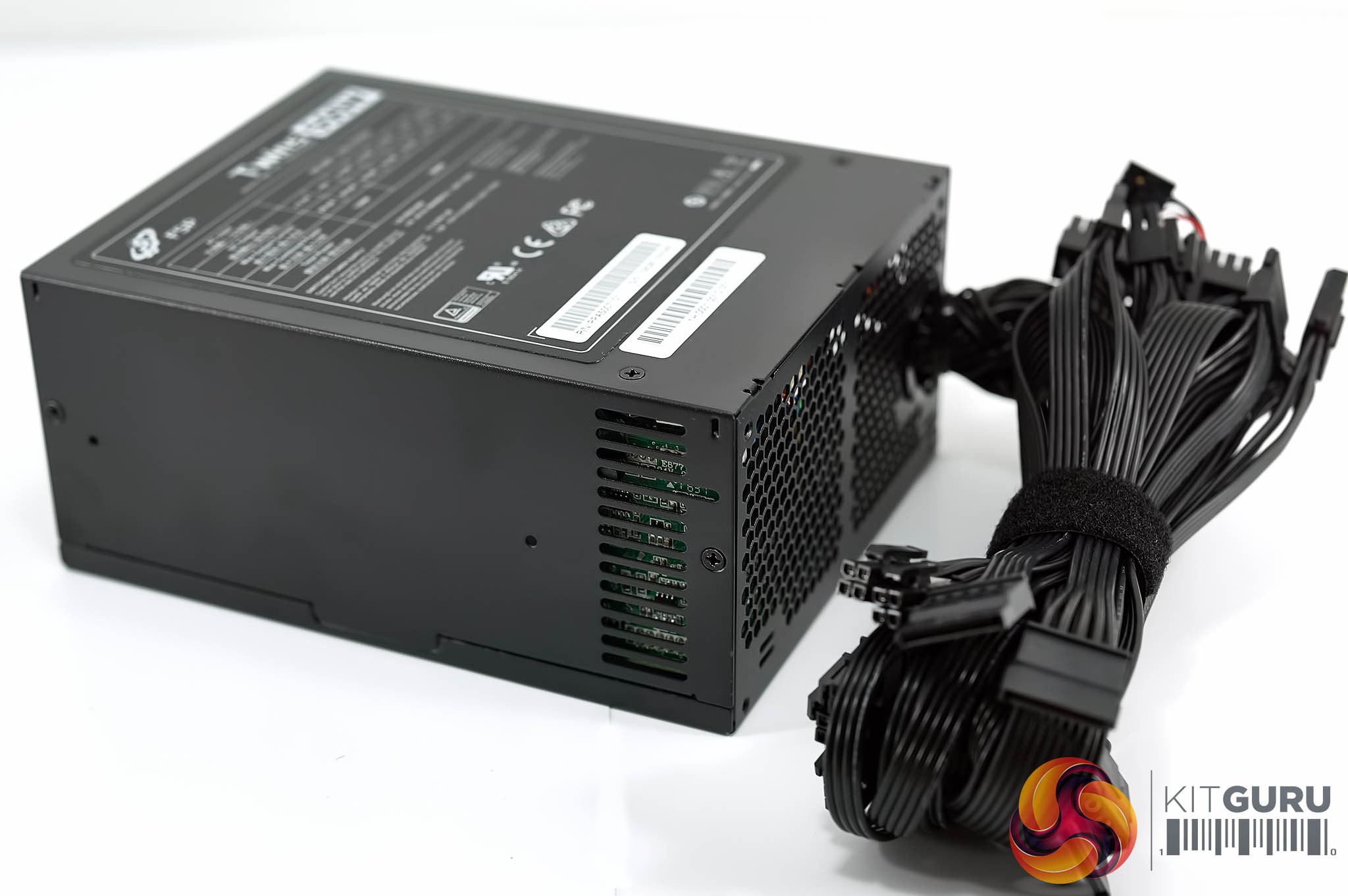
The ATX chassis is included in the second box and contains basically the ATX outer shell along with the hardwired cables which we discussed in more detail on the previous page.
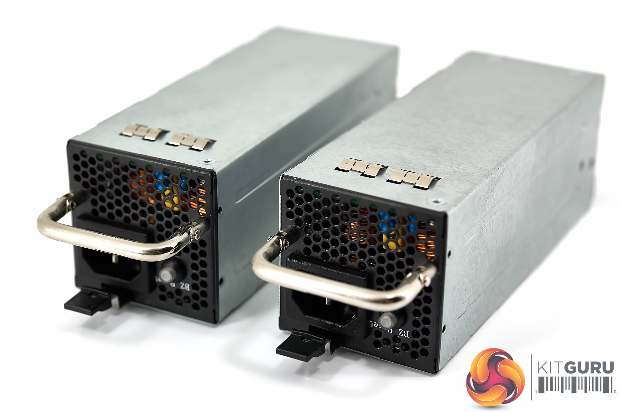
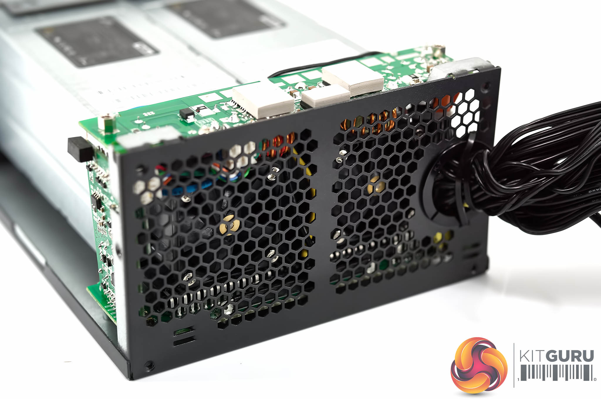
Each of the power supplies is long and thin without any paintwork on the chassis. One side has a vent and a handle, as well as a locking pin row. The other side of each power supply has a fan attached to ensure there is enough air flow.
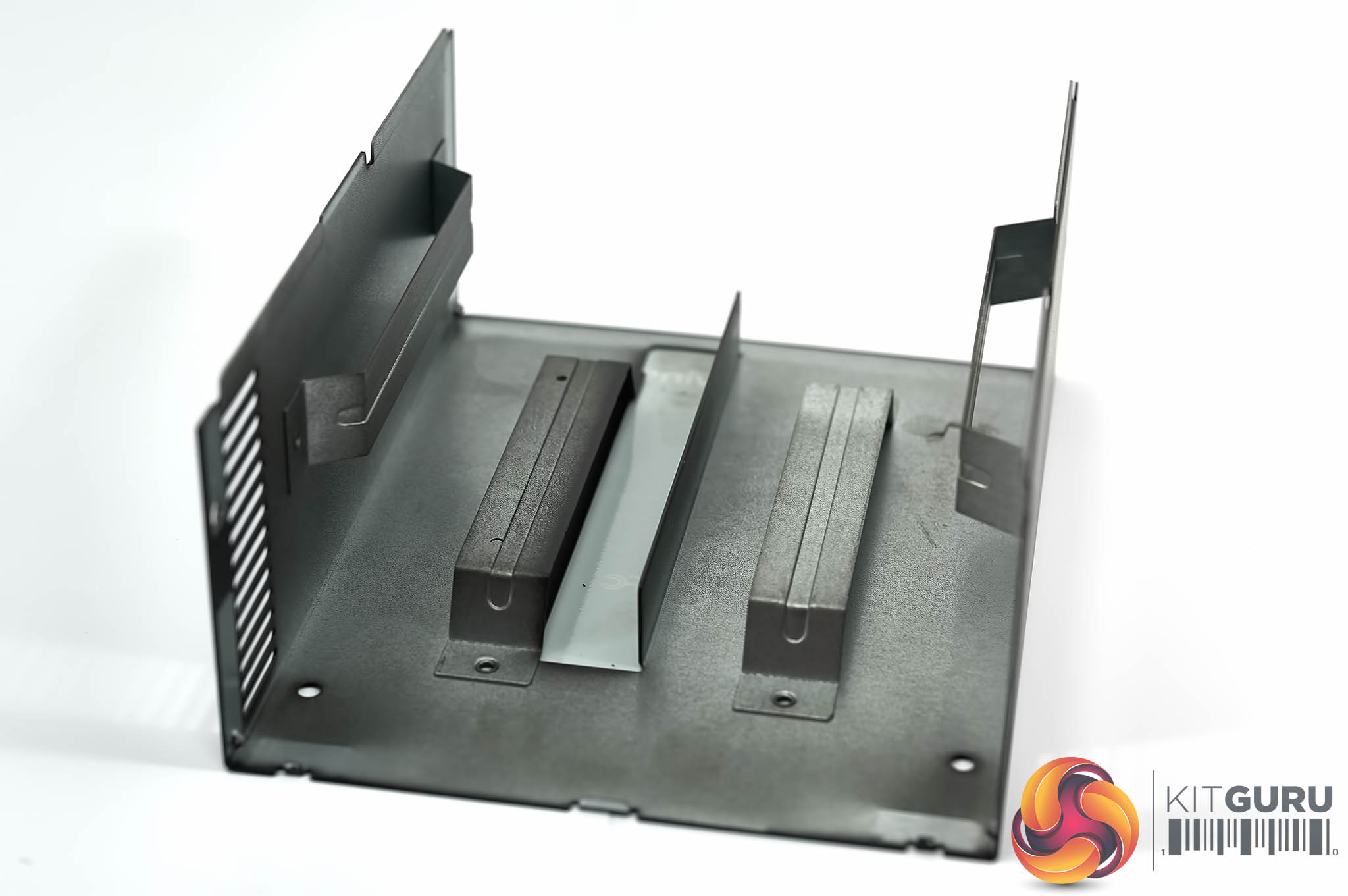
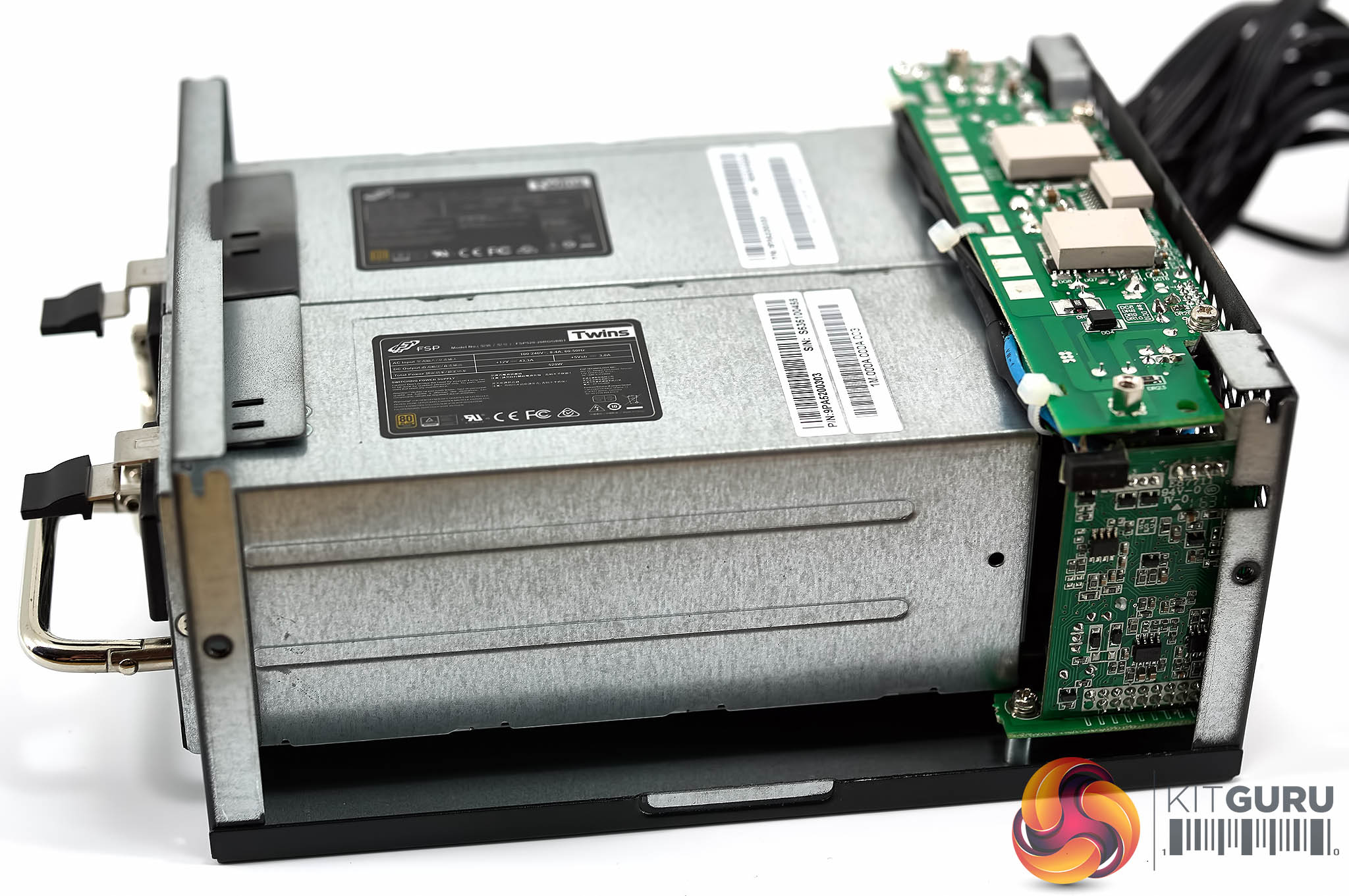
Below, a GALLERY showing an inside view of the ATX chassis and the two power supplies installed inside.
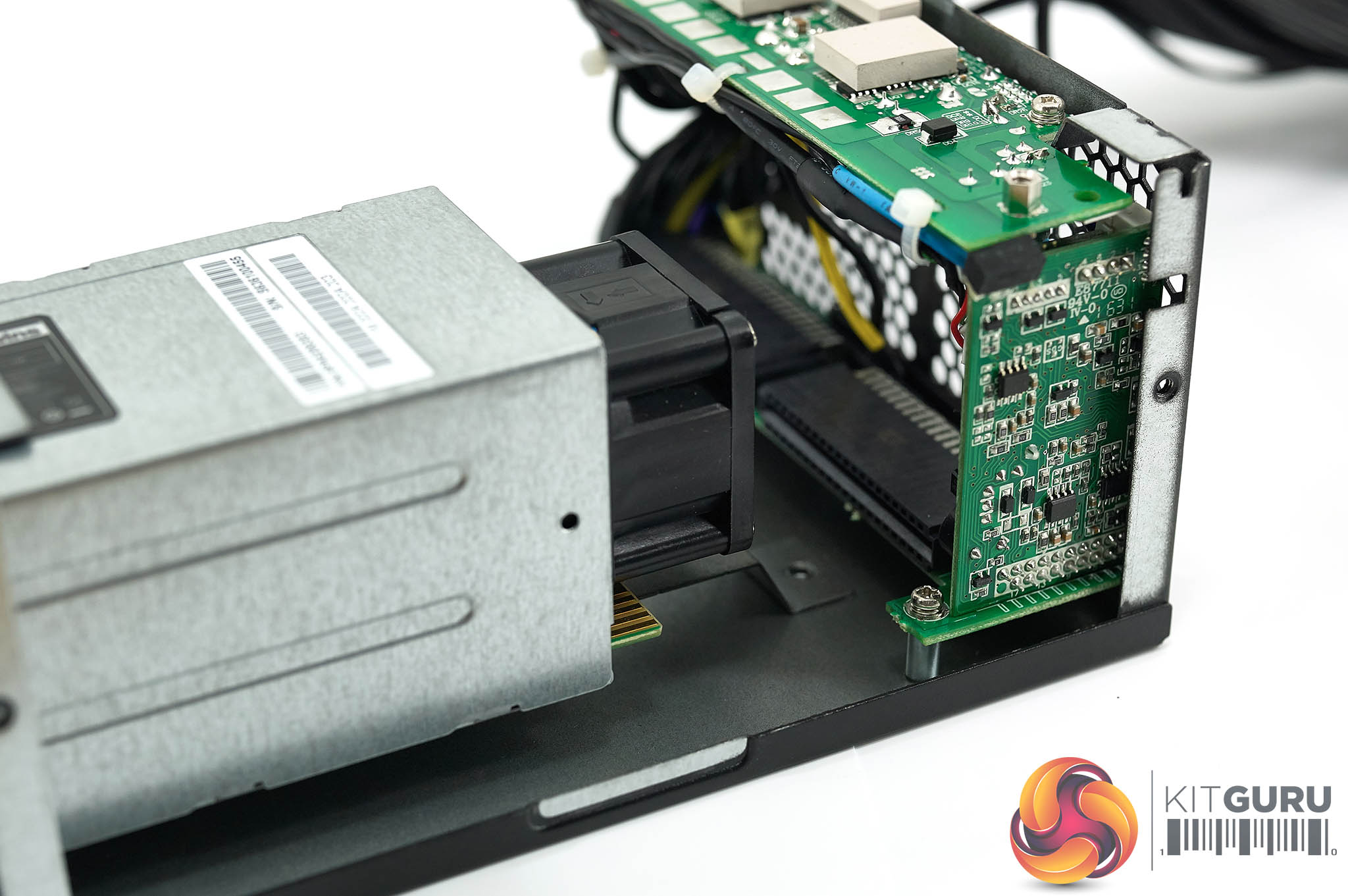
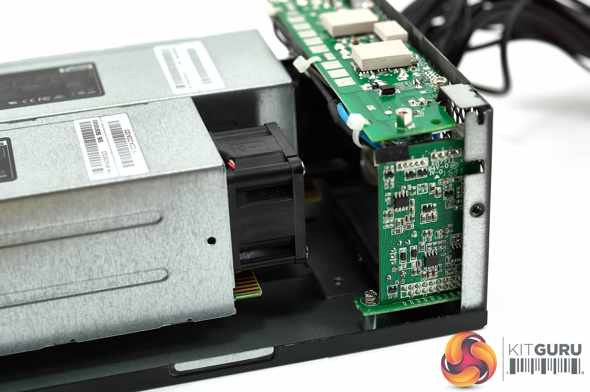
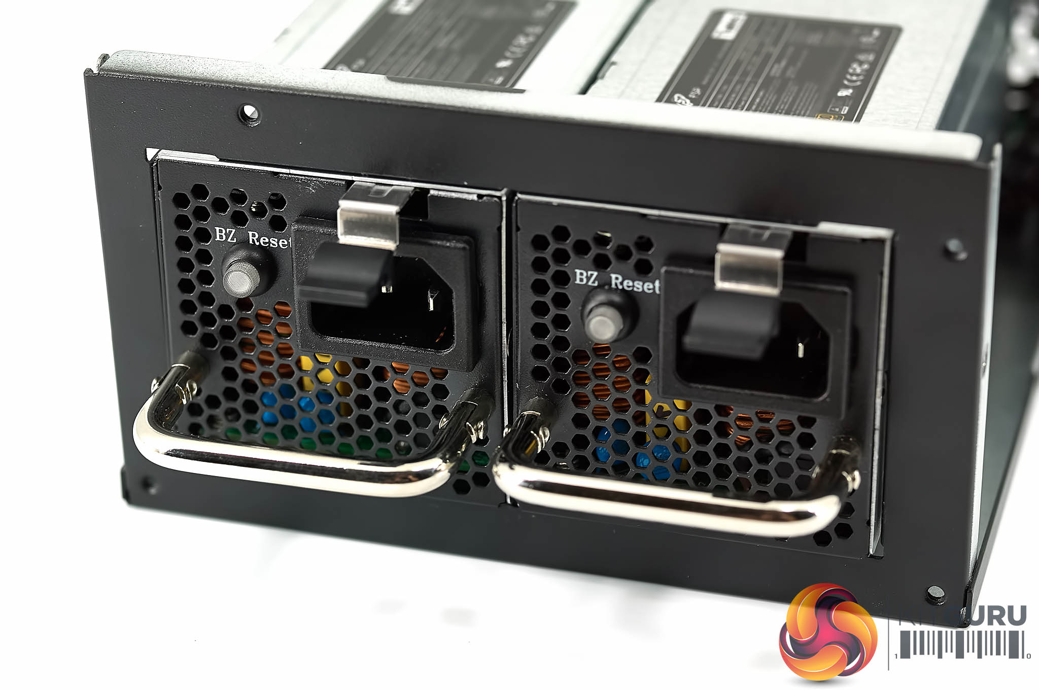
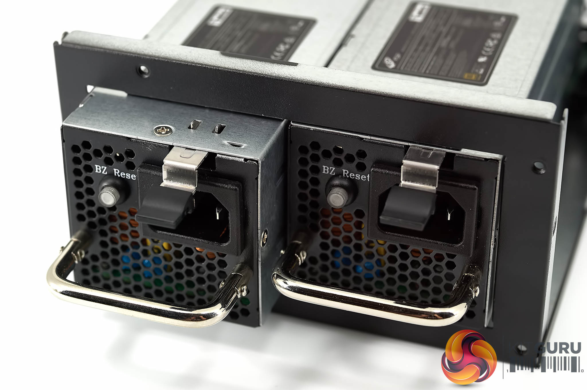
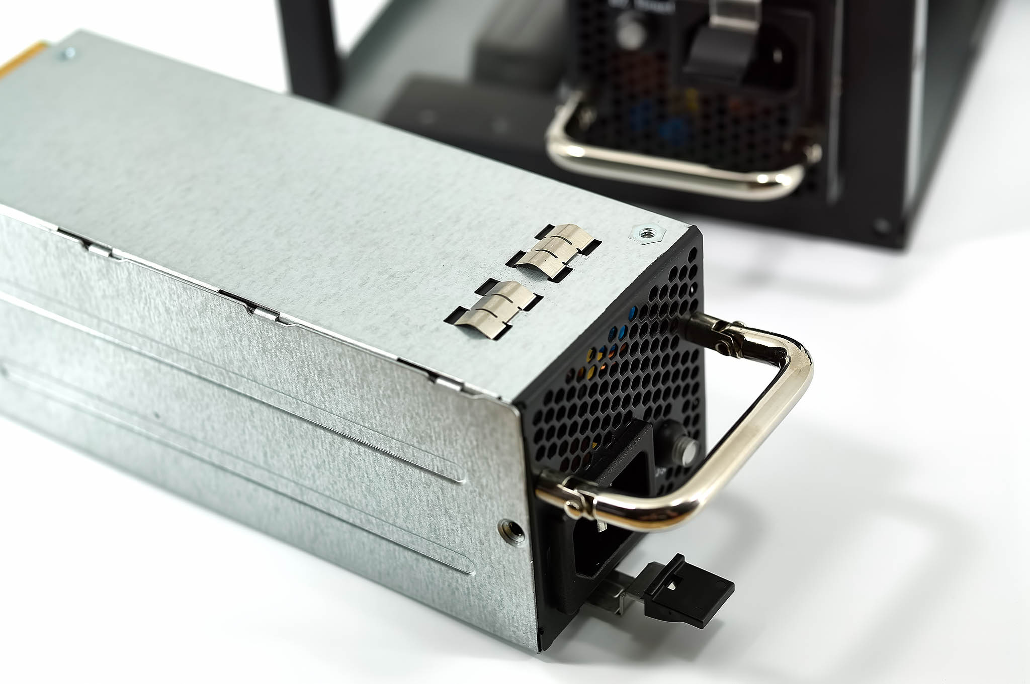
Each of the power supplies slides into the ATX housing and locks to the outer wall with a pin/lever system. Removing the power supplies is straightforward – push on the lever above the handle and pull out. Both are hot swappable, meaning if one fails, you can easily replace it without any downtime – this is incredibly important if you are running an important server or workstation and can't afford any downtime at all.
A red light is a sign of a problem, green indicates normal operation. The user manual explains all the status modes in detail.
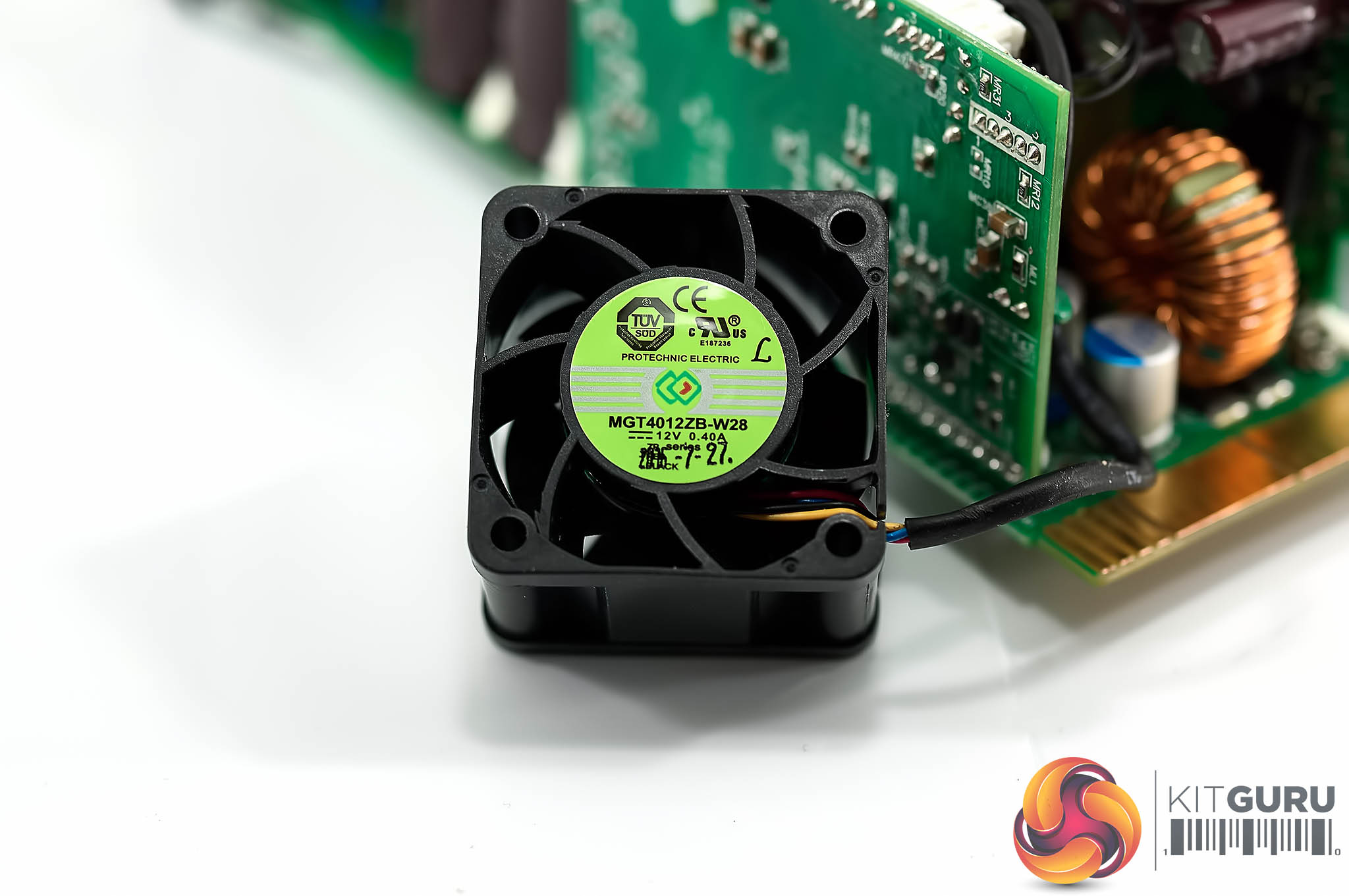
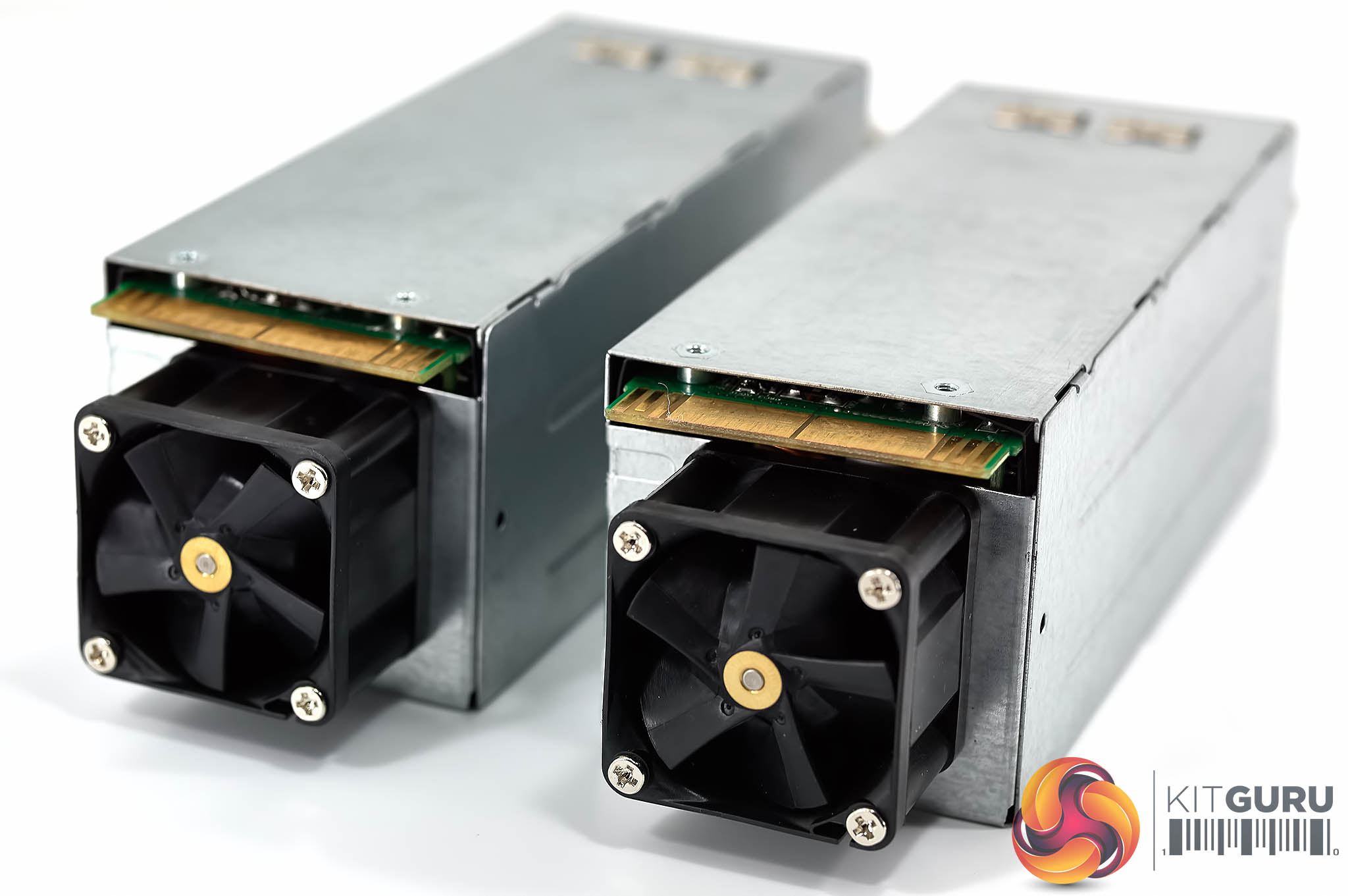
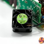
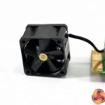
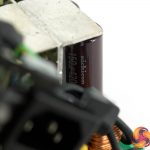
Each of the power supplies is fitted with a 40mm fan mounted on the front – this is a Protechnic Electric MGT4012ZB-W28 which is rated 0.49A at 12 VDC. It is a double bearing fan, especially important considering how fast these little fans may have to spin when each unit is under load.
I have always been outspoken against using small fans due to the noise they can emit, but in this kind of space restricted environment there is little choice.
![]()
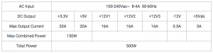
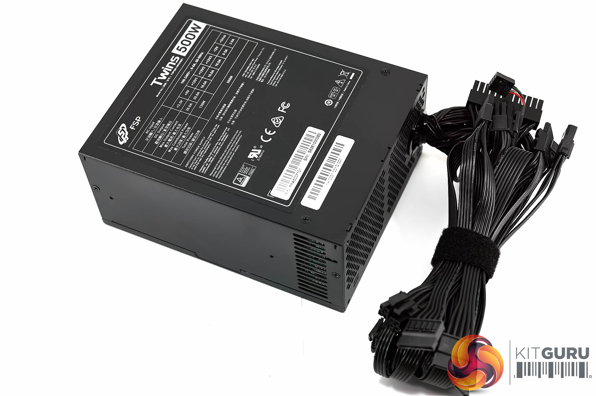
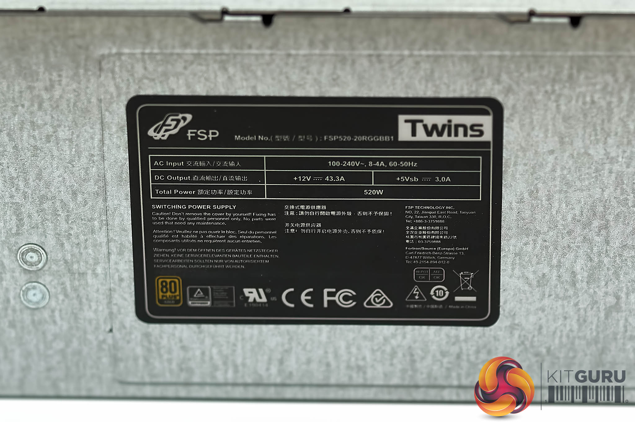
Each FSP power supply can handle 520 watts at a 50c rating and they adopt a single +12v rail at 43.3A which translates into 519.6W). The modular supplies incorporate a +5VSB output as well.
When both supplies are hooked into the main ATX sized chassis, the overall power rating is 500 watts. The architecture inside the main chassis frame combine the output of both units while generating the +3.3V, +5V and +12V outputs.
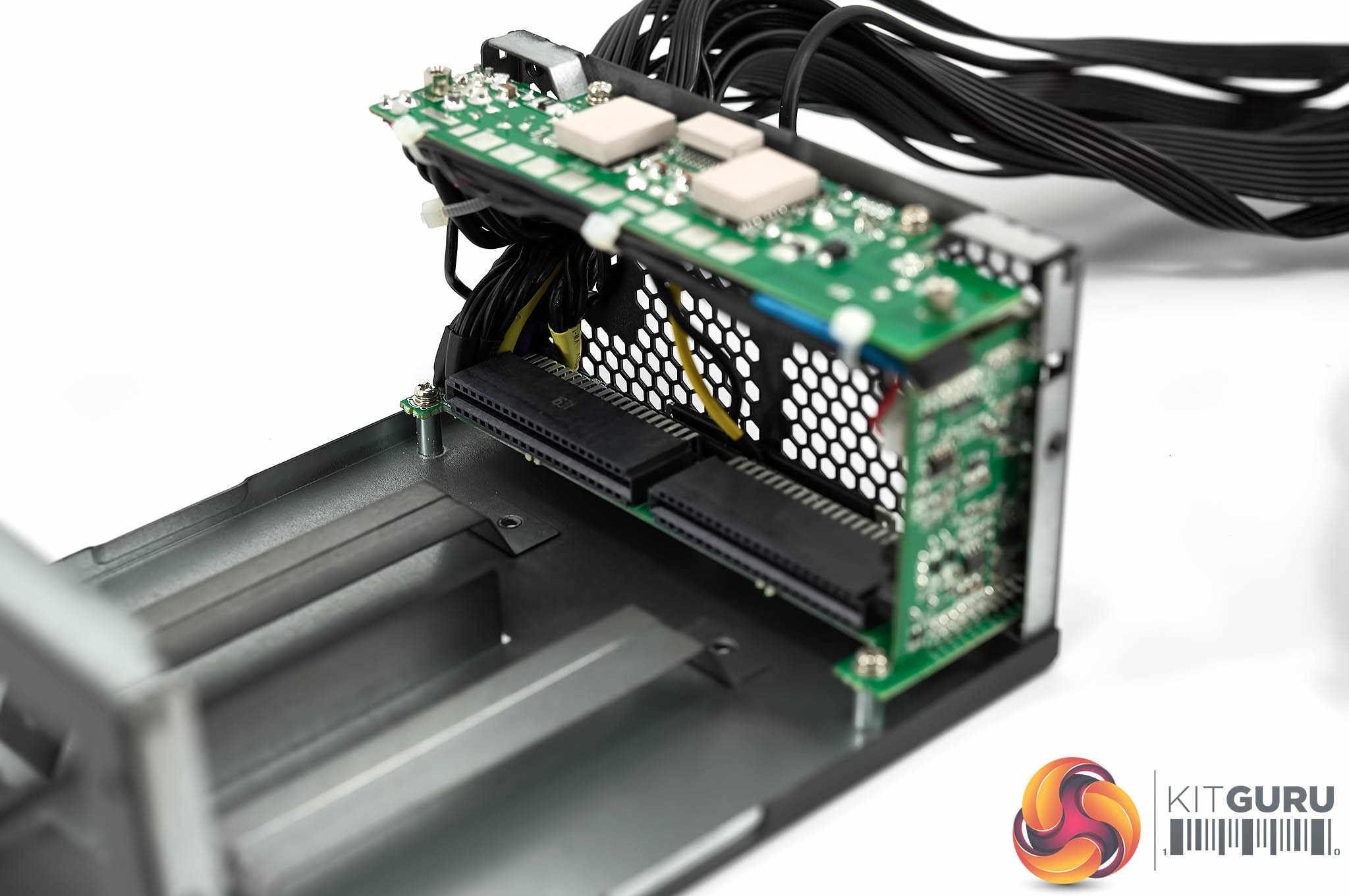
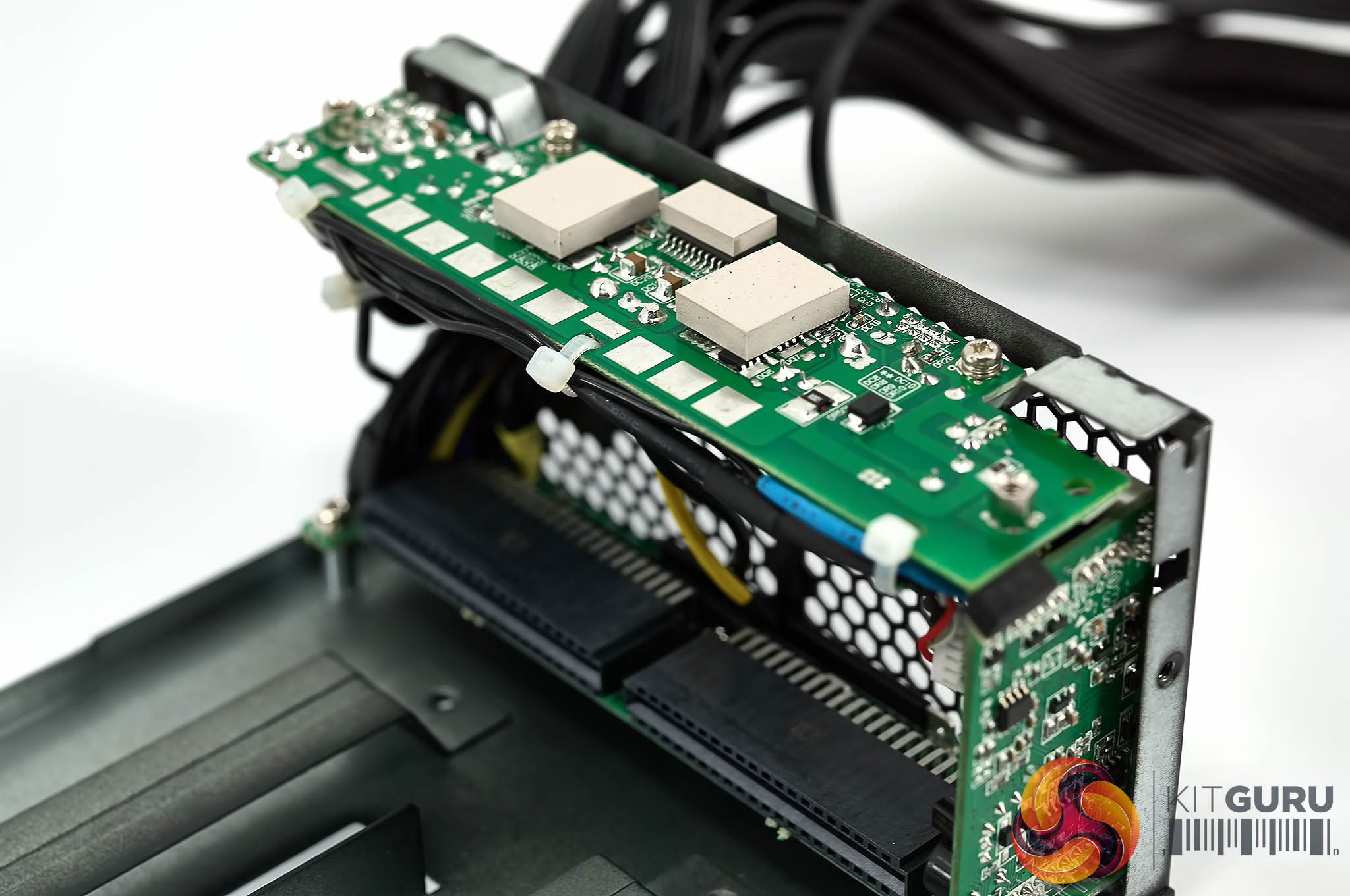
Below, a GALLERY showing an inside view of one of the power supplies which slide inside the main ATX chassis.
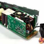
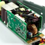
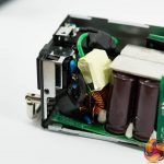
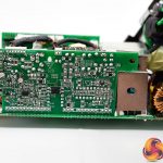
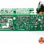
Internally, the OEM design is obviously by FSP. The two modular units plug into the main ATX chassis shown earlier on this page. There are multiple boards in the front that will handle the power distribution between the units. Remember when both power supplies are working fine, they share the load. The +3.3V, +5V and +12V outputs are generated on the main PCB inside the chassis. FSP adopt current limiters to switch the +12V output from the modular supplies into three 16A +12V outputs.
The overall build and construction is really exceptionally good and soldering seems very high grade throughout.