

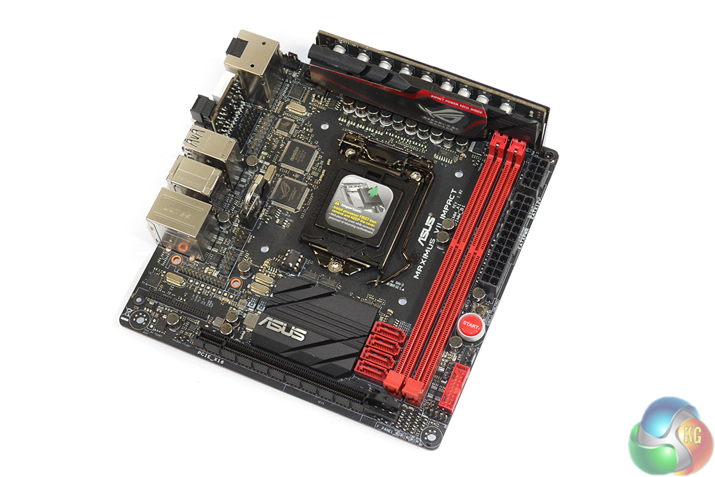
Fitting perfectly into the ROG series, Asus gives the Maximus VII Impact an appealing red and black colour scheme which is very well balanced.
Indicative of its mITX form factor, the PCB is crammed with components and clearance between the likes of DIMM slots and SATA connectors is tight. That is unlikely to cause inconvenience after the initial build phase, though.
On the topic of crammed PCBs, Asus decided that the 289 cm2 of surface area was simply not enough space to house all of the desired components. And that's why a total of five daughter boards are put to use.
Needless to say, space around the LGA 1150 CPU socket is tight. Tall memory modules and short down-draft CPU coolers are likely to interfere, but this board is as much designed for use with AIO watercooling units as it is low-profile heatsinks.
We had no clearance issues using a Noctua NH-D14 and Corsair's tall Vengeance Pro memory modules. Clearance under the heatsink was adequate for the VRM board and RAM heatspreaders. Taller modules, such as Kingston HyperX Predator sticks, simply aren't going to fit under large coolers.
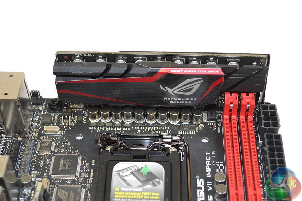
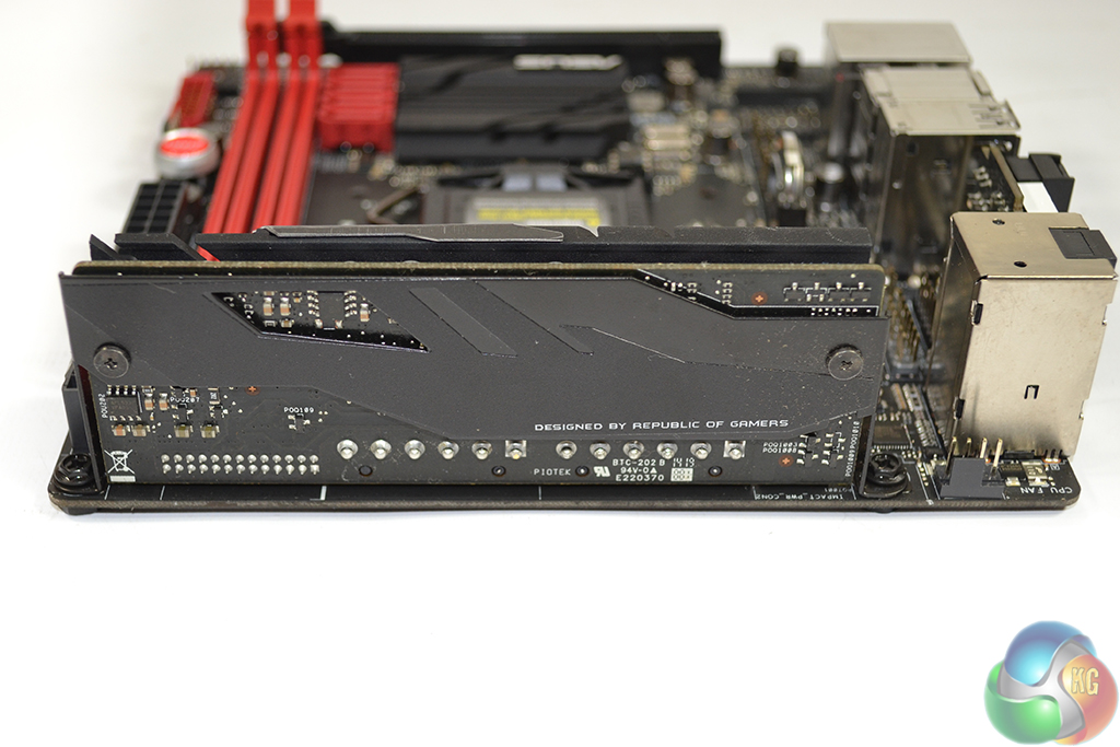
Arguably the most predominant feature of the Maximus VII Impact is its Impact Power II VRM daughter board. This pre-fitted PCB provides the CPU with an eight-phase power delivery system and the memory with a further two power phases.
Electronic components found under the sizeable front-mounted heatsink include the highly-respected Texas Instruments NexFET MOSFETs and 60A BlackWing chokes. 10K-rated ‘Black' capacitors are dispersed around the partnering power delivery components.
One of Asus' proclaimed benefits of the segregated power delivery board is EMI reduction. Having the electronic components mounted to a separate PCB can, in theory, reduce the level of interference and power phase distortion between susceptible electronic components.
Up to 16GB of DDR3 memory can be installed in the Maximus VII Impact's two single-latched DIMM slots. Speeds of up to 3300MHz are claimed to be supported, but this will also rely on the performance of other hardware, such as the CPU's memory controller.
The shorter memory traces between the CPU socket and DIMM slots are touted as the reason for the Maximus Impact boards' excellent memory overclocking capacity. The Maximus VI Impact's ability to contest memory frequency world records was proof of the mITX board's overclocking capability.
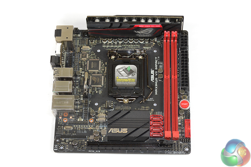
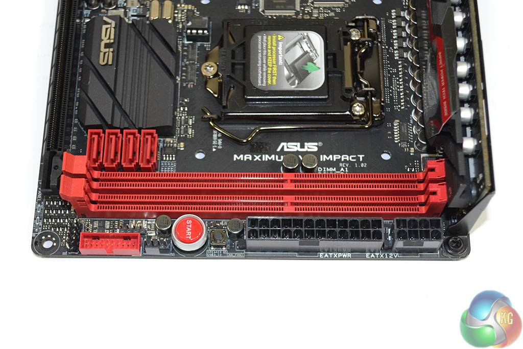
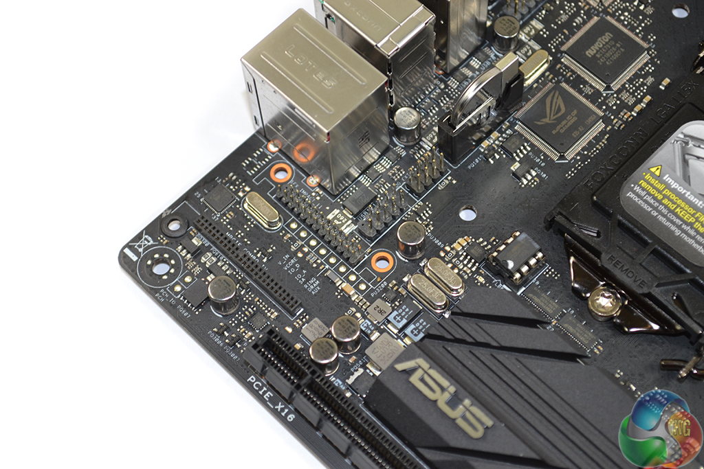
I like the right-edge positioning of the 24-pin and 8-pin power connectors. This mounting location keeps them well away from the interference-ridden zone that is the CPU socket and its surroundings. Connecting and disconnecting power cables is an easy task, void of awkward angles and confined spaces.
Power and reset buttons are placed beneath the 24-pin connector on the board's right edge. For standard users, this positioning is smart because it keeps them away from the blockage created by a large graphics card. The same logic applies for the Z97-fed USB 3.0 header.
One negative of the onboard power button's positioning is its close proximity to the DIMM slots. When sub-zero cooling pots are strapped onto memory modules, the power and reset buttons are almost certain to freeze over, forcing overclockers to switch their power-up method. That's why Asus' front panel header extension cable is so convenient.
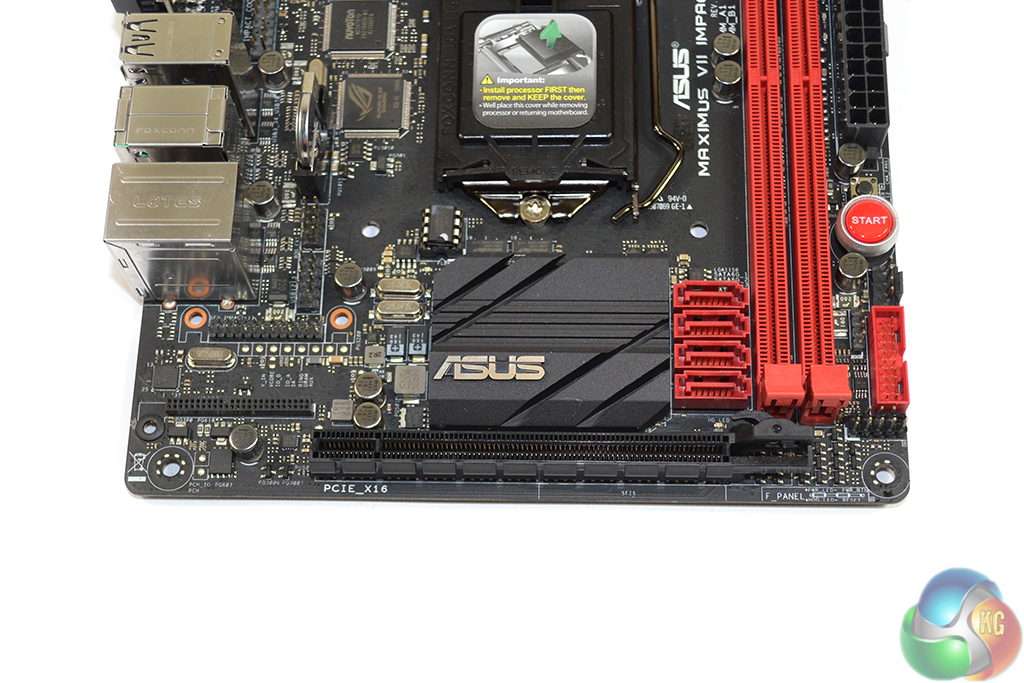
A single full-length PCIe 3.0 x16 slot gives users the capacity to install any graphics card that uses the interface. Asus deploys a smart latching mechanism that is still usable even with the clearance issues created by large CPU coolers (such as our tested Noctua D14).
When available, a full sixteen-lane connection from the CPU is fed to the PCIe slot. This will drop to a (still sufficient) eight-lane PCIe 3.0 link when a high-bandwidth M.2 device is installed.
All four of the outwards-facing SATA 6Gbps ports are provided by the Z97 chipset. A black, low profile heatsink acts as the cooling device for said chipset.
An array of headers is dotted about the board. Beneath the USB 3.0 header are the front panel connections.
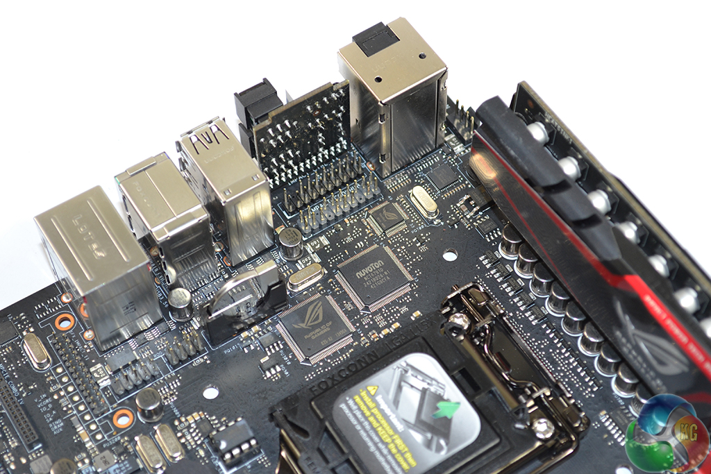
Behind the pre-mounted Impact Control II board are TPM and Cool Hub fan board headers. Two iROG chipsets are situated close to the Nuvoton NCT6791D monitoring chip.
Left of the PCIe slot is the mPCIe Combo Card connection, with the SupremeFX Impact II audio board's header situated above it. In close proximity are a USB 2.0 header and the ROG connect port.
Just beneath the audio board header are eight of the ten Probelt voltage read points, with the other two sitting in the board's bottom-left corner. I am not a fan of the decided location, as accessing the points when a graphics card is installed will be a tricky procedure. A point on the board's right edge would have been preferable.
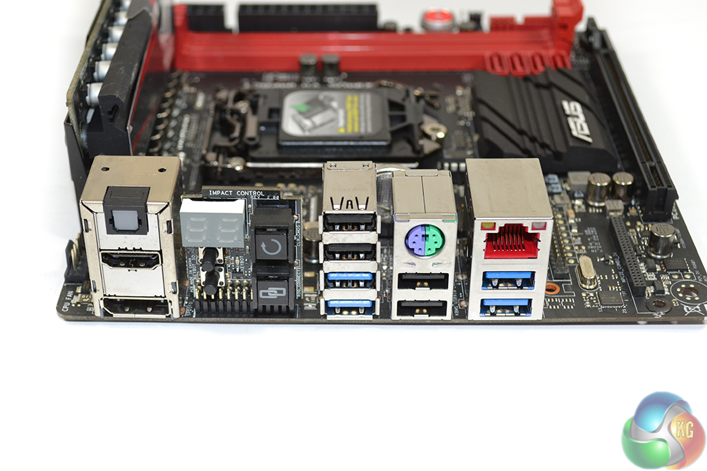
Four chipset-fed USB 3.0 ports and a further four USB 2.0 connections are found on the board's rear IO. A PS/2 keyboard/mouse port is provided for overclockers. Gigabit Ethernet is driven by an Intel I218-V chipset, with Asus' enhanced electronic circuitry and GameFirst III software support.
HDMI, DisplayPort, and optical audio connectors make use of the onboard audio and video capabilities.
The pre-mounted Impact Control II board consists of useful input devices that are situated in an interference-free area. Theclear CMOS and ROG connect buttons and two-digit debug LED will be of most use to overclockers. Also convenient for gamers is the easy access to KeyBot and SoundStage buttons.