

Following on from part one of our WD Blackout special build project, today we pick up where we left off. Towards the end of the first video, I spoke about the idea of making a DIY distro plate to sit on top of the Phanteks P600S power supply shroud and started making a template of the distro plate layout. In part two, I take the idea from a cardboard template to an actual working model made from several cast acrylic sheets. But will the idea be a success? Let’s find out.
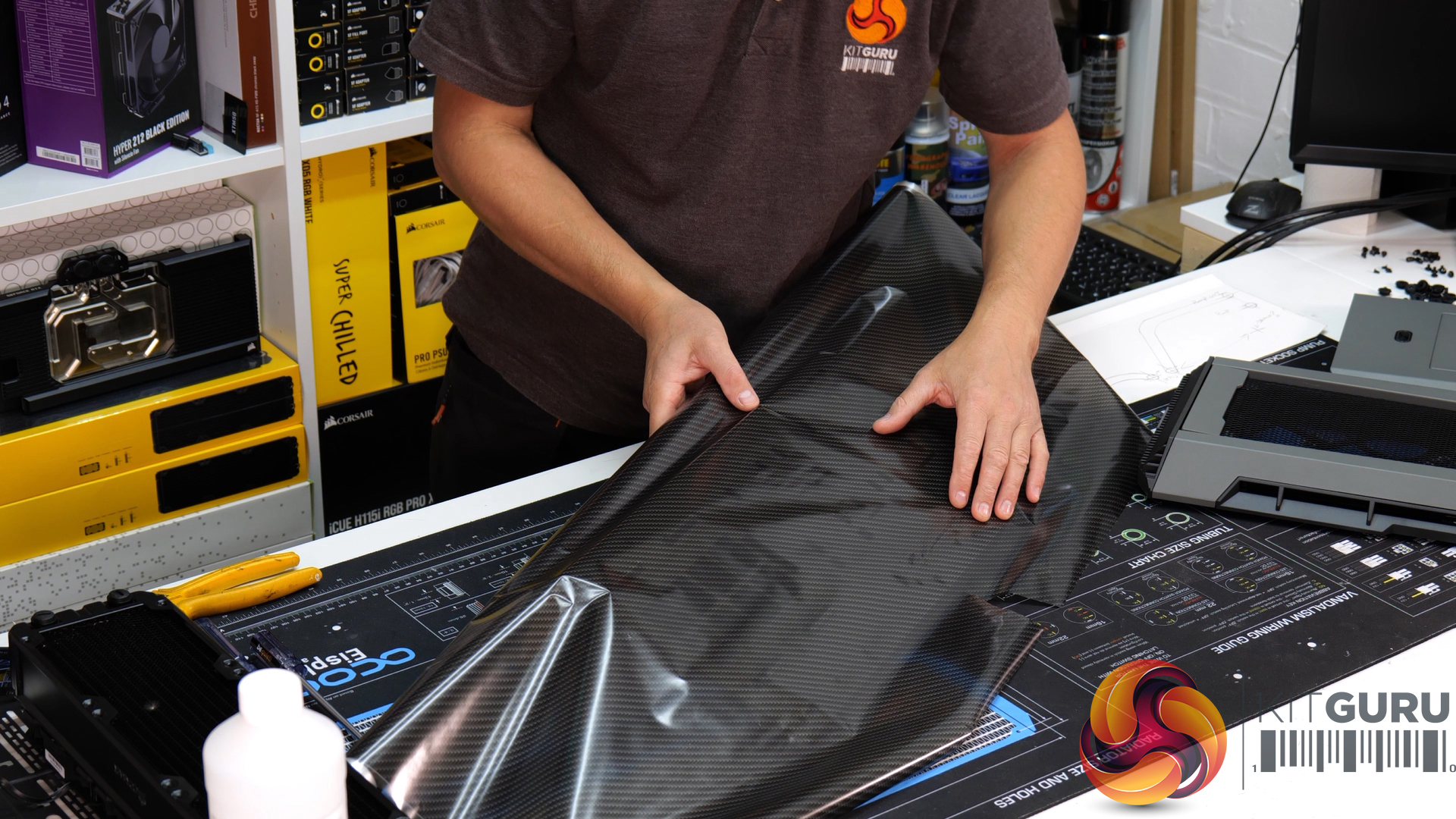
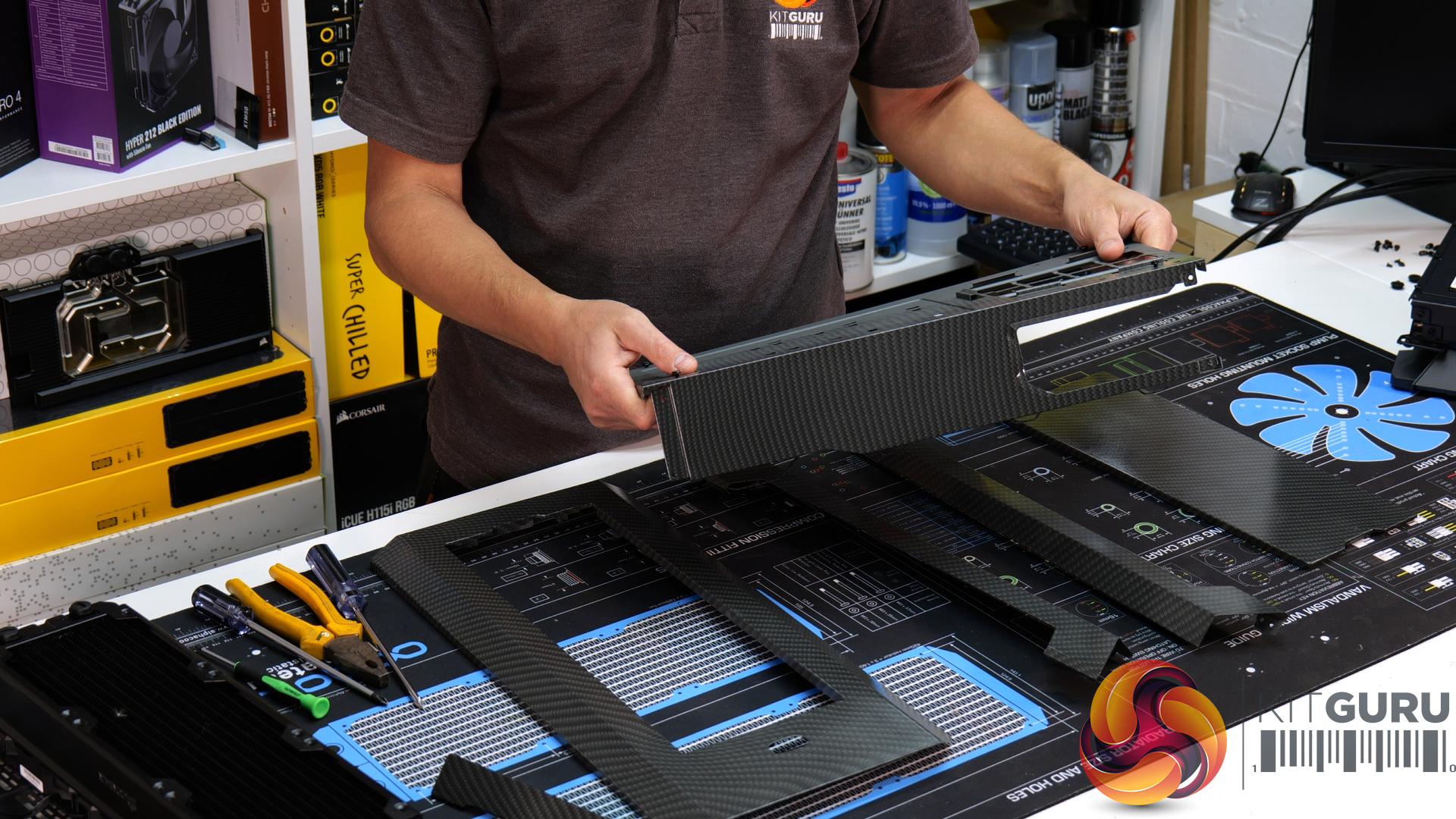
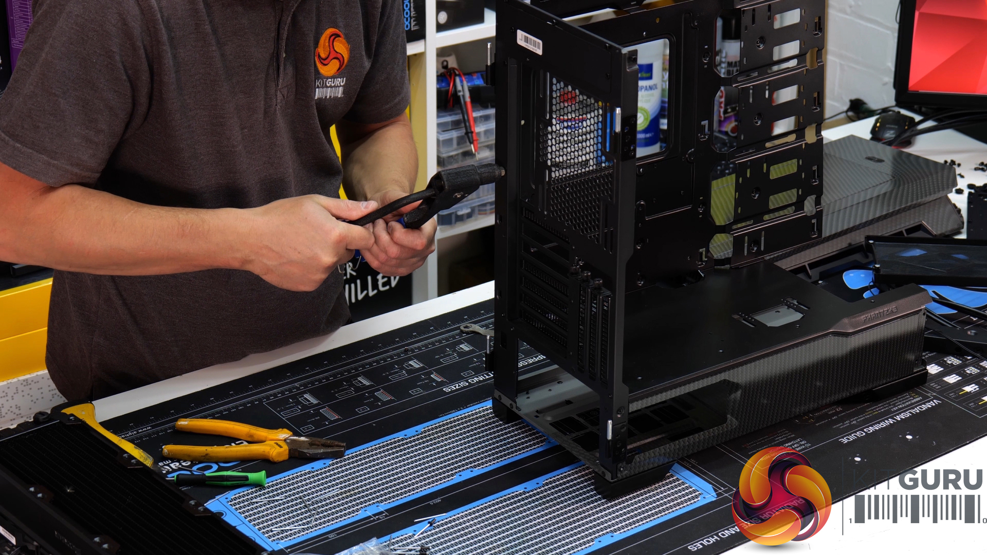
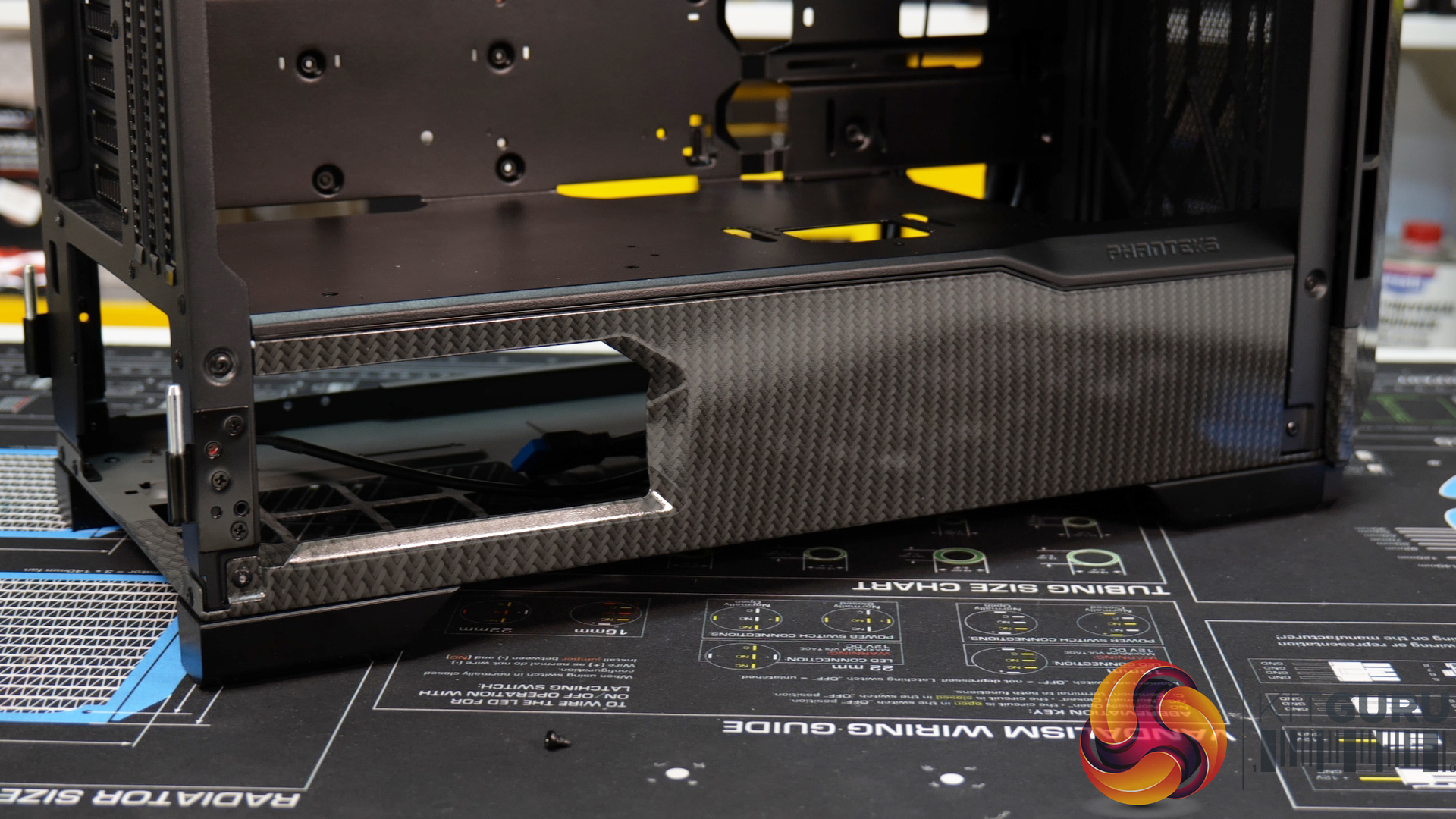
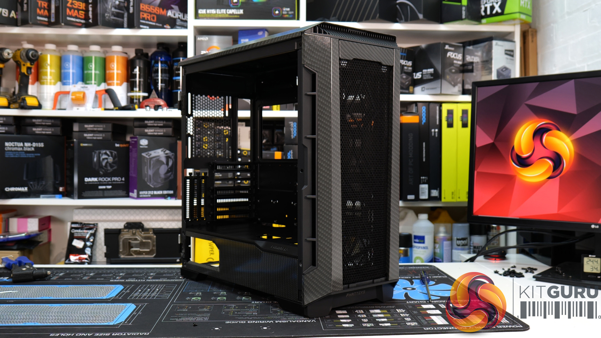
We are a little behind schedule with part two of this build due to me being ill and losing my voice for a week (which is not ideal when making videos)… despite that I managed to get on with some case mods while my voice was out of action. The opening section of WD_Blackout Part two focuses on those case mods as well as the DIY distro plate. The Phanteks P600S chassis was completely dismantled, which allowed me to individually hydro dip a block carbon effect film on most of the outer panels and the power supply shroud.
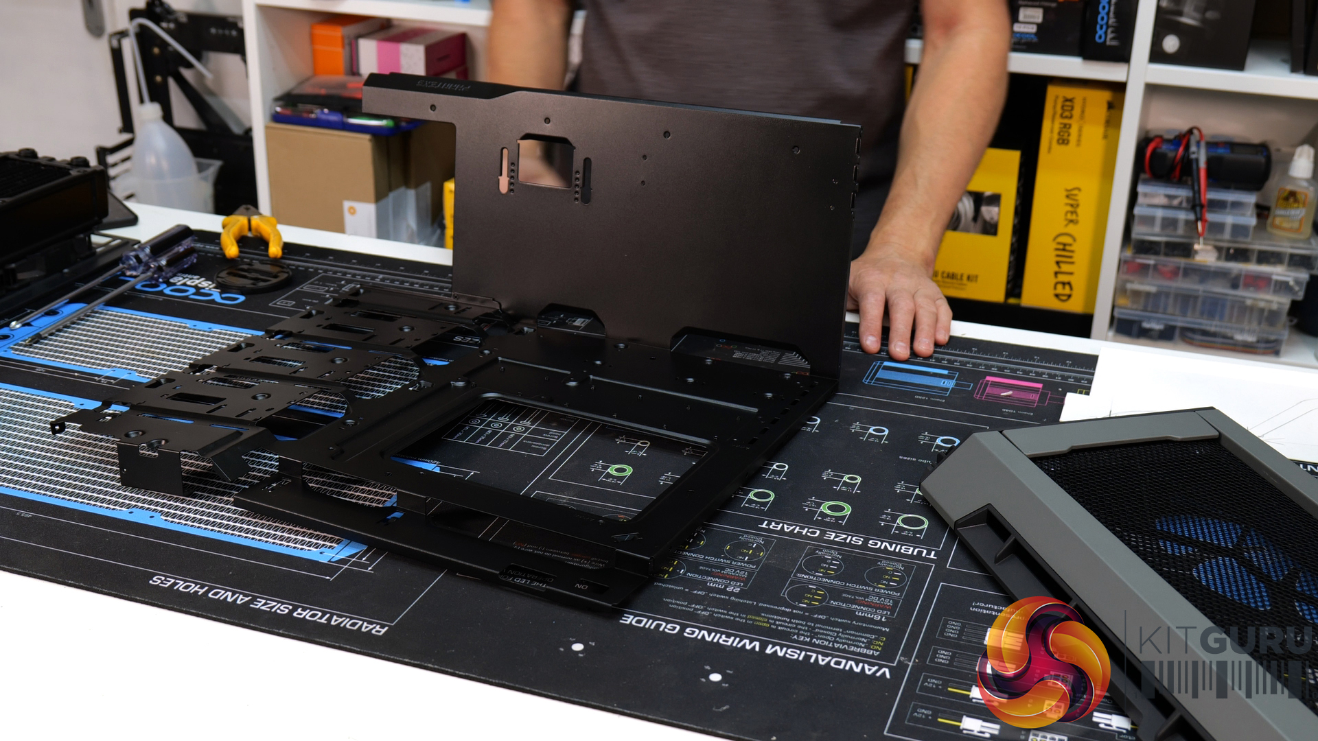
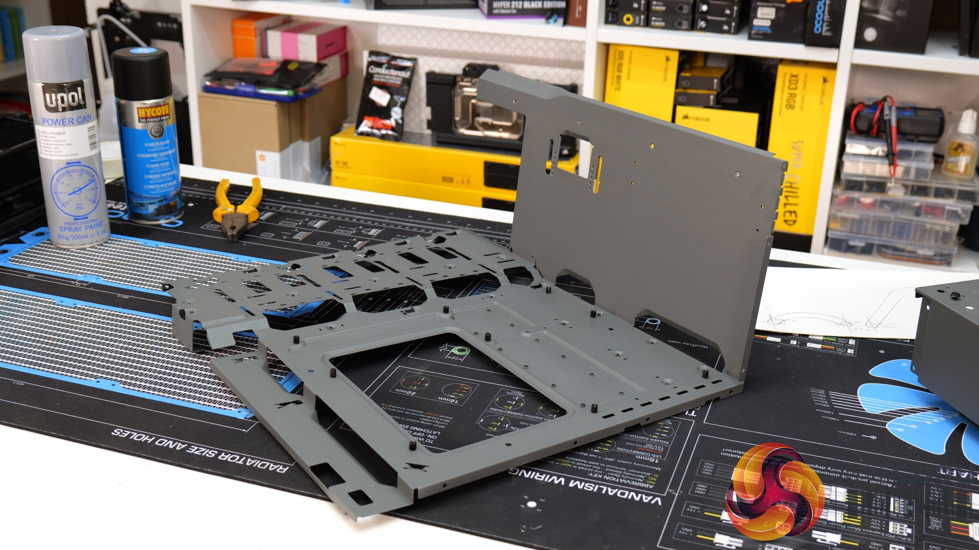
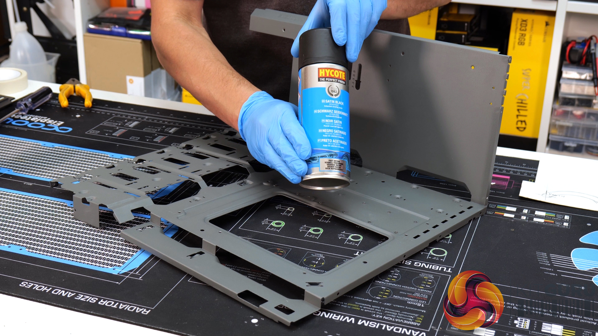
The motherboard tray was treated with a coating of spray primer, then finished with a satin black spray paint coating to match the internal blackout theme. As well as hydro dipping and painting, the right-hand steel side panel and the central steel front panel have been sent away for laser cutting. The right-hand panel will have a WD_Black laser-cut logo and a WD logo on the front panel, both logos will be backed with bright coloured acrylic to help them stand out.
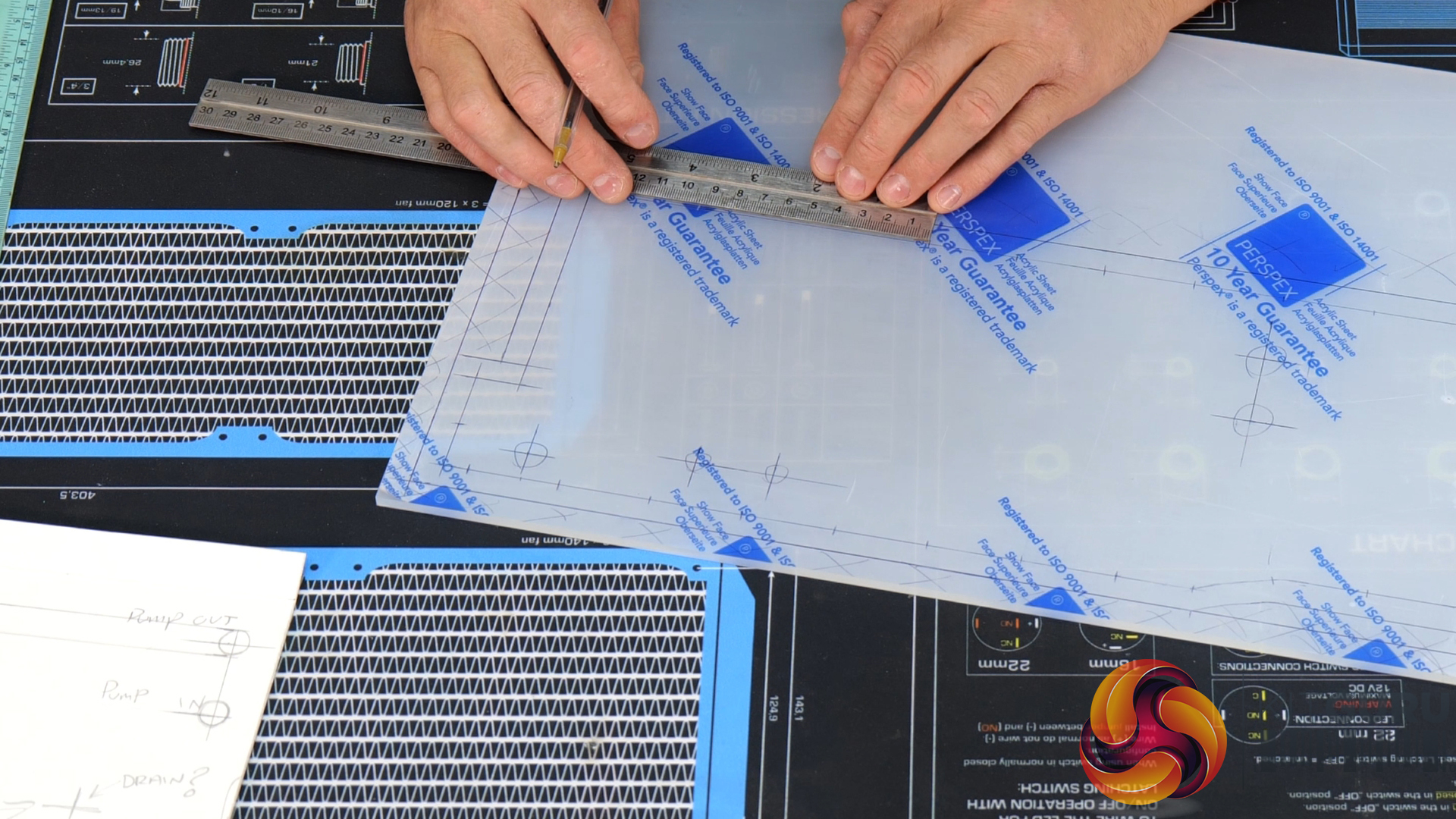
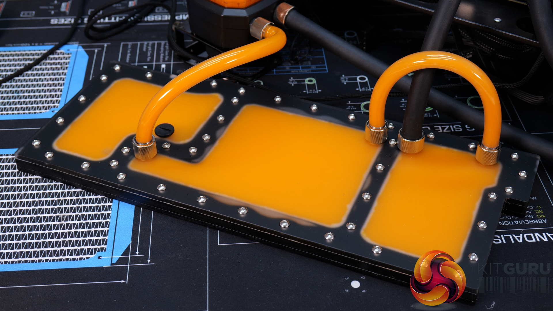
Once my voice had recovered enough to start talking on video again, I made a start on constructing the DIY distro plate that will sit on top of the Phanteks P600S PSU shroud. The plan for this distro plate is to make all the hard tubes in the custom loop position in a vertical orientation, so alignment between hardware components and the inlet/outlet ports will be critical for this idea to work as intended.
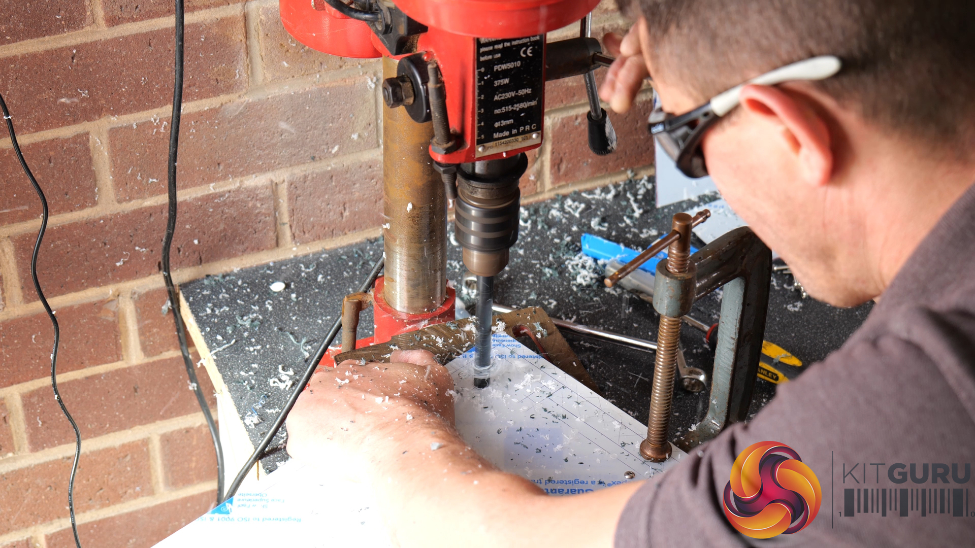
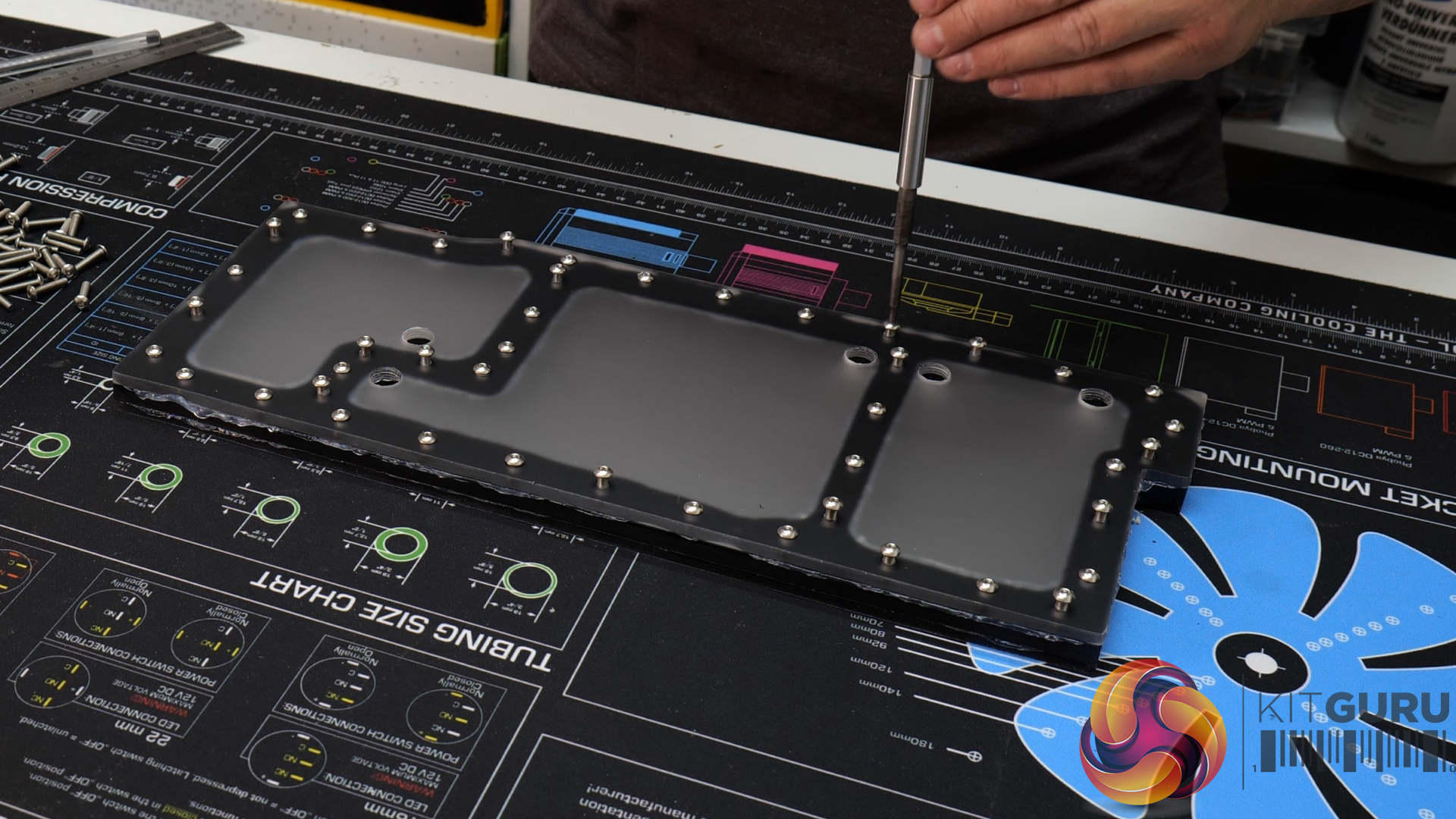
As you can see from the video, the distro plate is made from three pieces of cast acrylic sheet, an 8mm central sheet and 5mm upper and lower covers. With no easy access to CNC machines for this project, I proceeded to make the distro plate entirely by hand using common tools that most DIY enthusiasts may already own, including a pillar drill, jigsaw, various size drill bits, metric taps and readily available sealants.
Materials used to construct the distro plate:
- 8mm thick cast acrylic Perspex sheet.
- 2 x 5mm thick cast acrylic Perspex sheets.
- M4 x 18mm button head stainless steel machine screws.
- Various adhesives/sealants.
- HSS jigsaw blades.
- M4 x 0.7 HSS metric coarse machine tap.
- G1/4 HSS machine tap.
- 3mm HSS drill bit.
- 5mm HSS drill bit.
- 8mm HSS drill bit.
Here are the steps taken to make the distro plate:
- Transfer the dimensions from the template to the acrylic sheet that will be used for the upper cover. I found that marking the protective film with the dimensions was done best by using a biro.
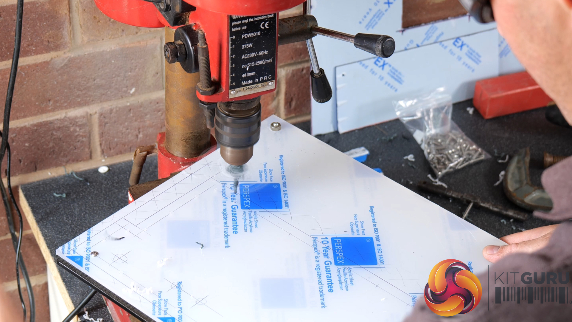
- Clamp all three pieces of acrylic together using g-clamps and bolting the sheets together in a waste area that will be cut off.
- Drill out all screw holes through all three pieces of acrylic while clamped together, I used a 3.3mm drill since m4 screws were being used to hold the plate together.
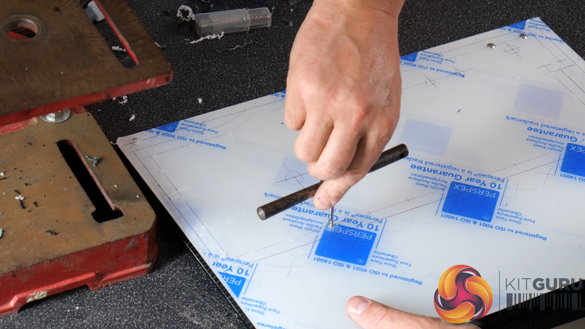
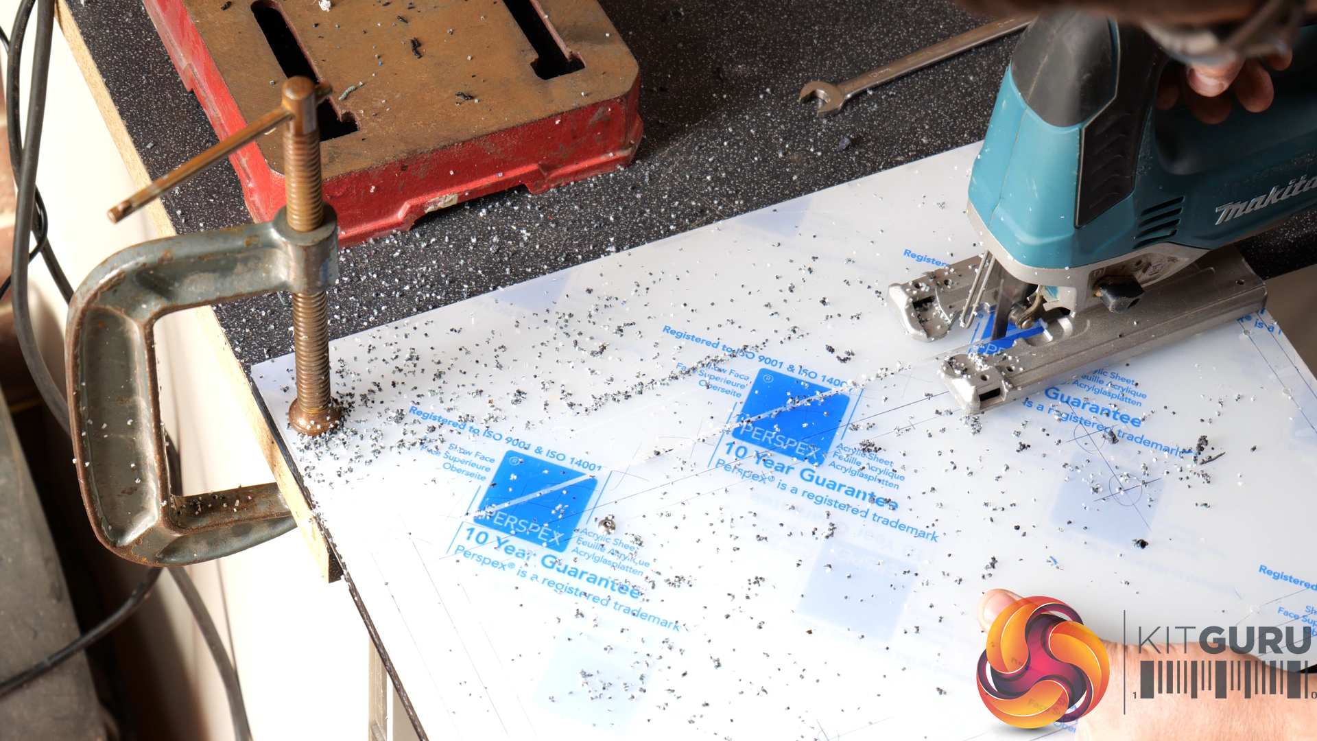
- I then ran an m4 machine tap through the screw holes while the three acrylic sheets were still clamped together. Next, using a jigsaw set to a slow speed with a fine HSS cutting blade, I cut out the outline shape of the distro plate.
- I then widened the screw holes in the upper two sheets of acrylic to 4.5mm using a HHS drill bit in the drill press, cut out the water channels in the acrylic's central piece, and then bonded and clamped the three acrylic sheets together using adhesive and m4 machine screws.
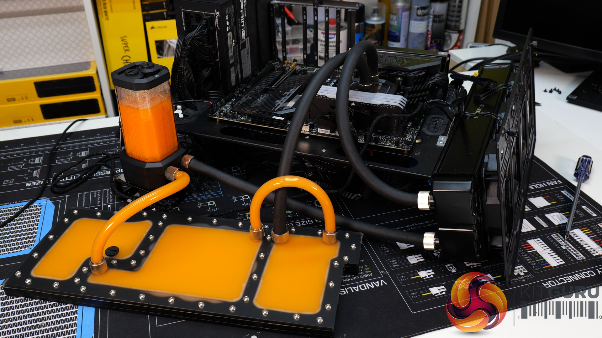
I initially tried using clear RTV silicone sealant to form a seal around the mating flange of the distro plate but the silicone looked insufficient very quickly, so I dismantled the plate and used a different sealer that is an adhesive as well as a sealant. I then tested the seal's water-tightness by connecting up the distro plate to my test bench and stress testing the CPU for a prolonged period.
The result isn't perfect, however, after almost three hours of constant CPU stress testing the distro plate was still watertight. Almost instantly after switching the pump on, pressure built in the distro plate which blew the seal slightly around the main liquid compartment, not enough to cause a leak but it was enough to affect the aesthetics of the plate.
The CPU temperature during stress testing remained constant at around 65⁰C, peaking at 68⁰C which is perfectly acceptable. So, the distro plate is very close to being a successful DIY project, a little more work on the seal, testing different sealant/adhesive is needed before I declare it a complete success which is what ill be working on for the next video, as well as assembling the final system to complete this project build in part 3.
Discuss on our Facebook page HERE.
KitGuru says: A little more testing with adhesives and sealants is needed for this DIY distro plate project to be a complete success, but I will not let it beat me. Make sure you stick around for part 3 to see if it is a complete success.