
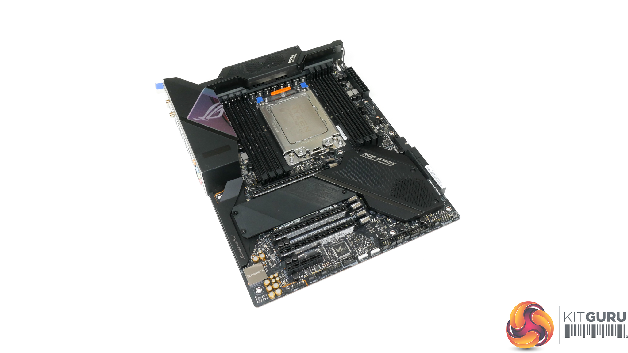
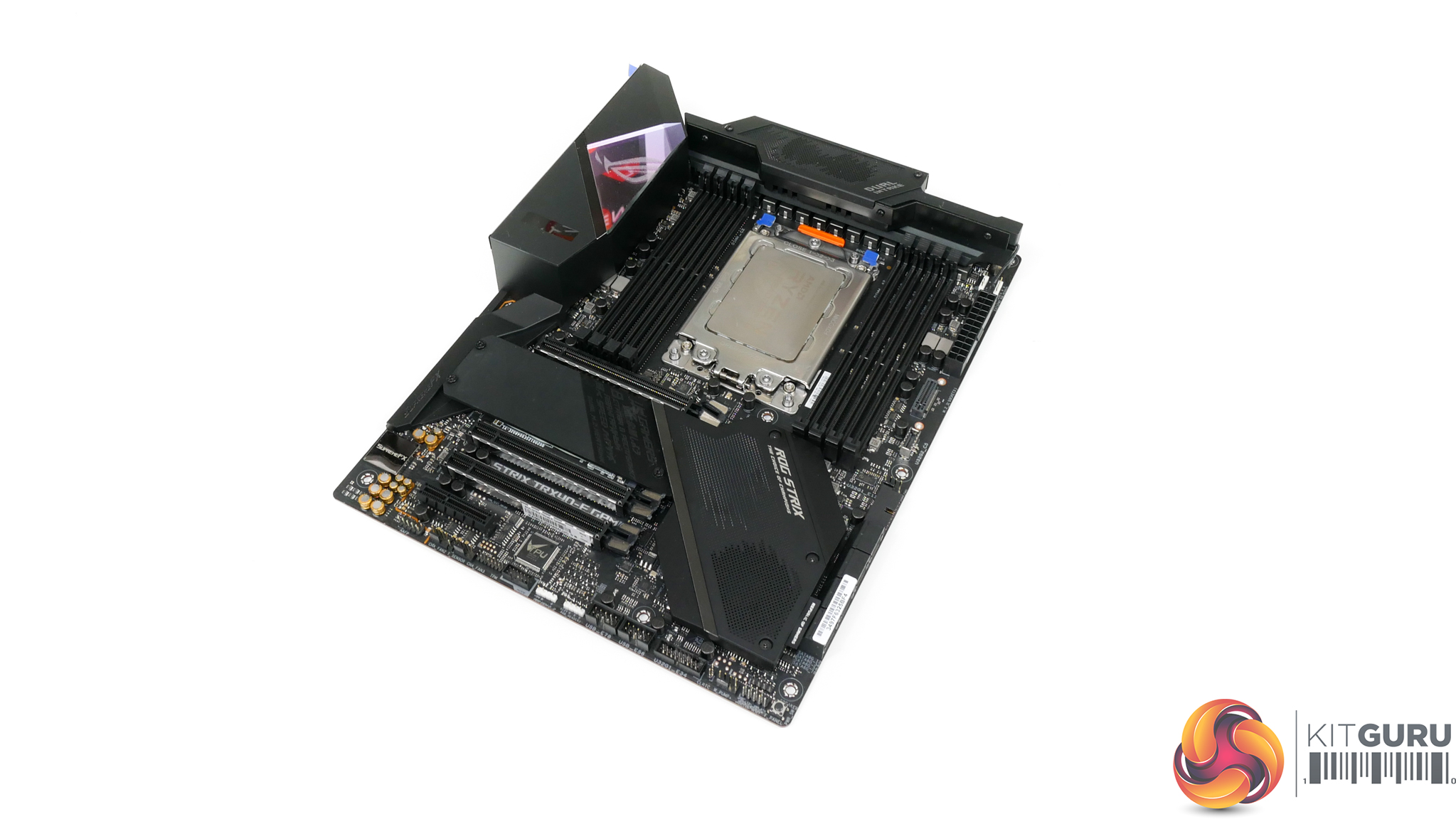
The ASUS ROG STRIX TRX40-E Gaming motherboard uses the usual styling for an ROG STRIX product. You get the dark black PCB and primarily dark black slots and connectors. ASUS relies upon the RGB lighting implementation to offer colour contrast.
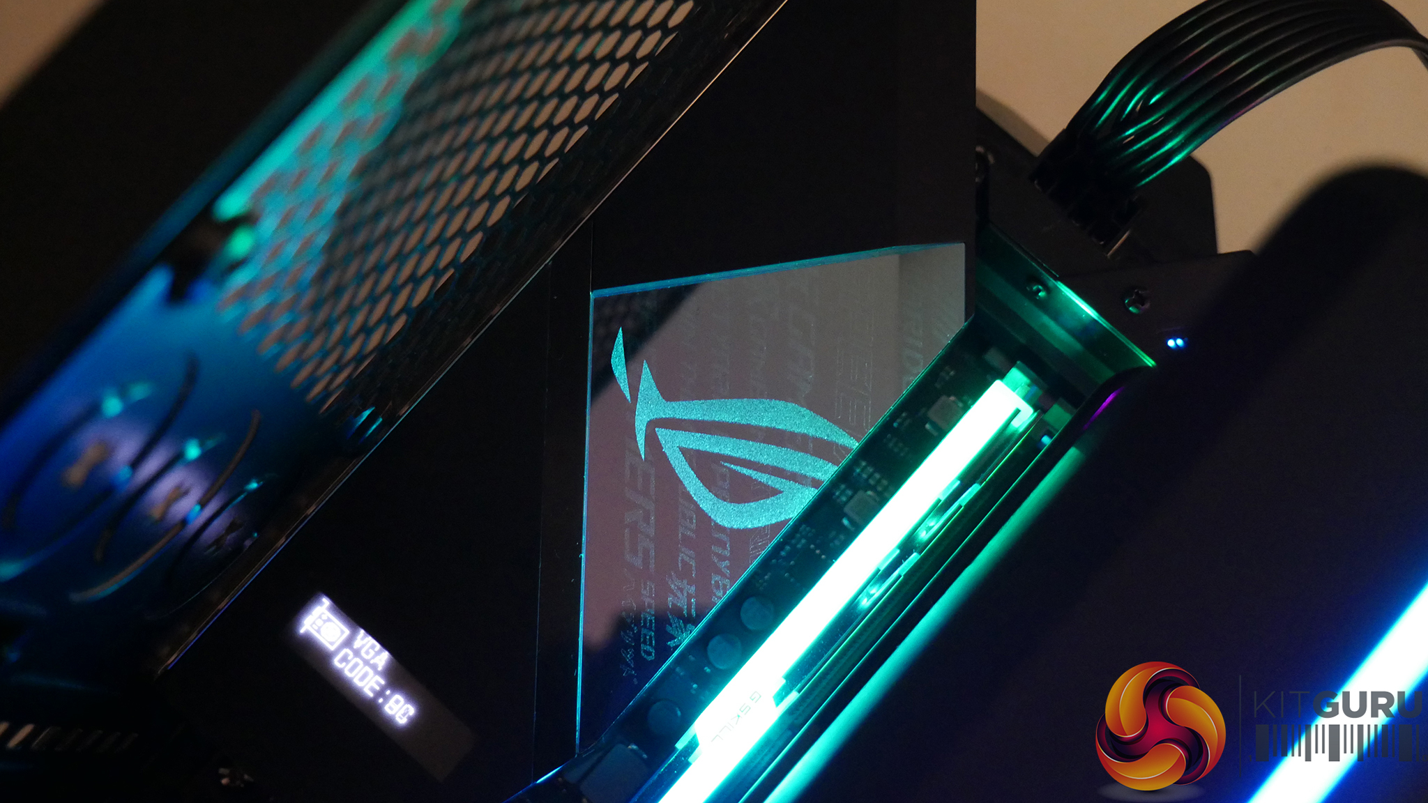
As is the norm for today’s premium motherboards, you get an integrated rear IO shield as well as a shroud. A plastic sheet is used to allow LED lighting to shine through and ASUS takes this opportunity to deploy its ROG logo.
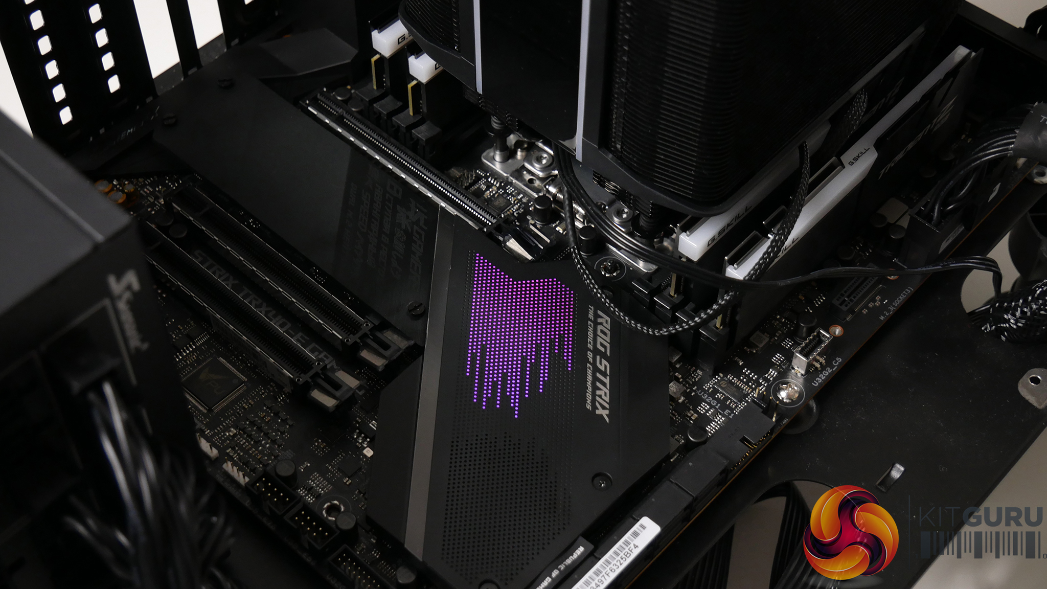
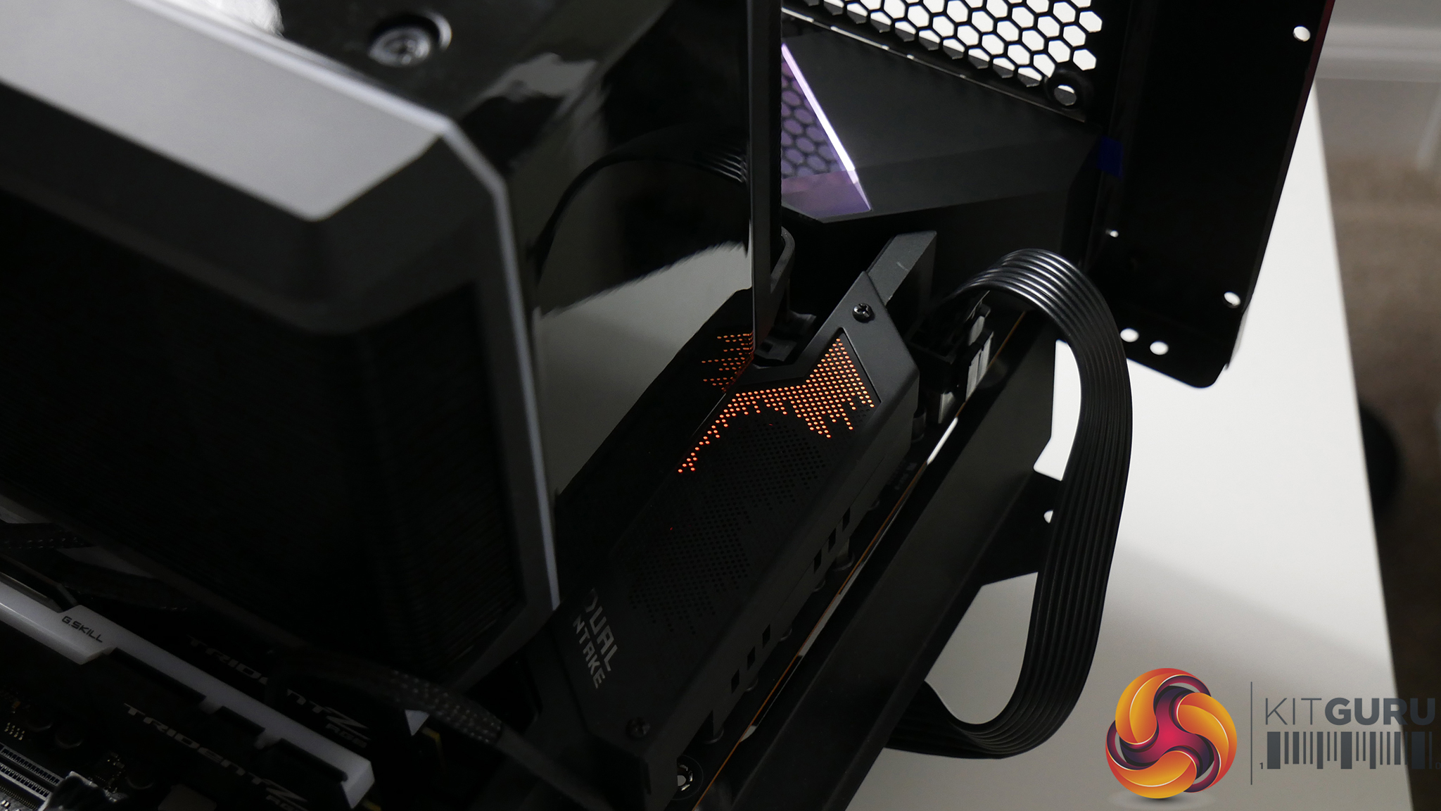
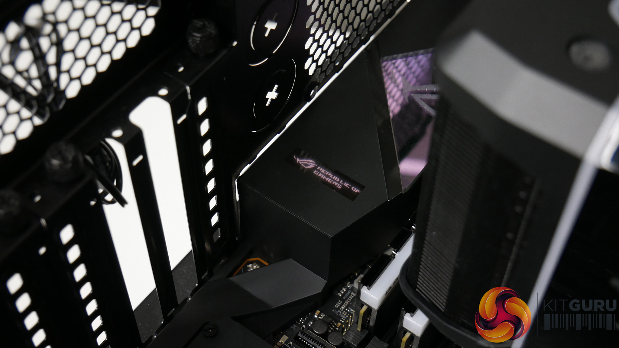
Three distinct lighting zones are provided with the TRX40-E Gaming motherboard. You get lighting on the rear IO cover, the VRM shroud, and the chipset heatsink. That last location is almost entirely blocked by the presence of a large graphics card and is therefore rendered rather pointless.
Notably, the TRX40-E Gaming also features a LiveDash OLED display on the rear IO shroud. This is useful as ASUS uses this screen to display operating characteristics in real time, such as the checks being done during POST. A cool feature indeed, and a useful one too.
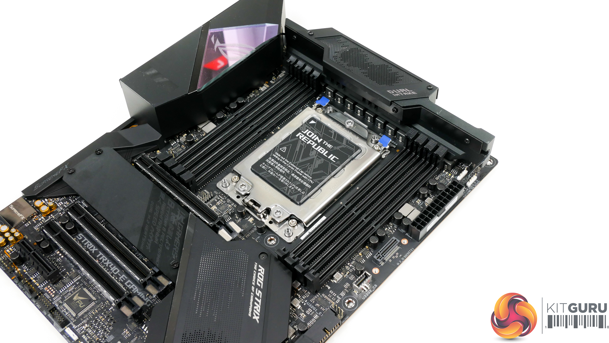
Given the TRX40 platform’s quad-channel memory capability, it is no surprise to see eight DDR4 DIMM slots deployed. Each of these slots features a single-latch mechanism and, on our sample, the latch position is switched between the left and right banks.
Official memory speed support is up to 3200MHz for Threadripper 3000 CPUs, depending on how many DIMMs are installed. But ASUS also quotes support for frequencies above 4600MHz via overclocking according to the QVL. With currently available 32GB non-ECC modules, you can install up to 256GB of memory. ASUS also supports certain ECC memory kits according to the QVL.
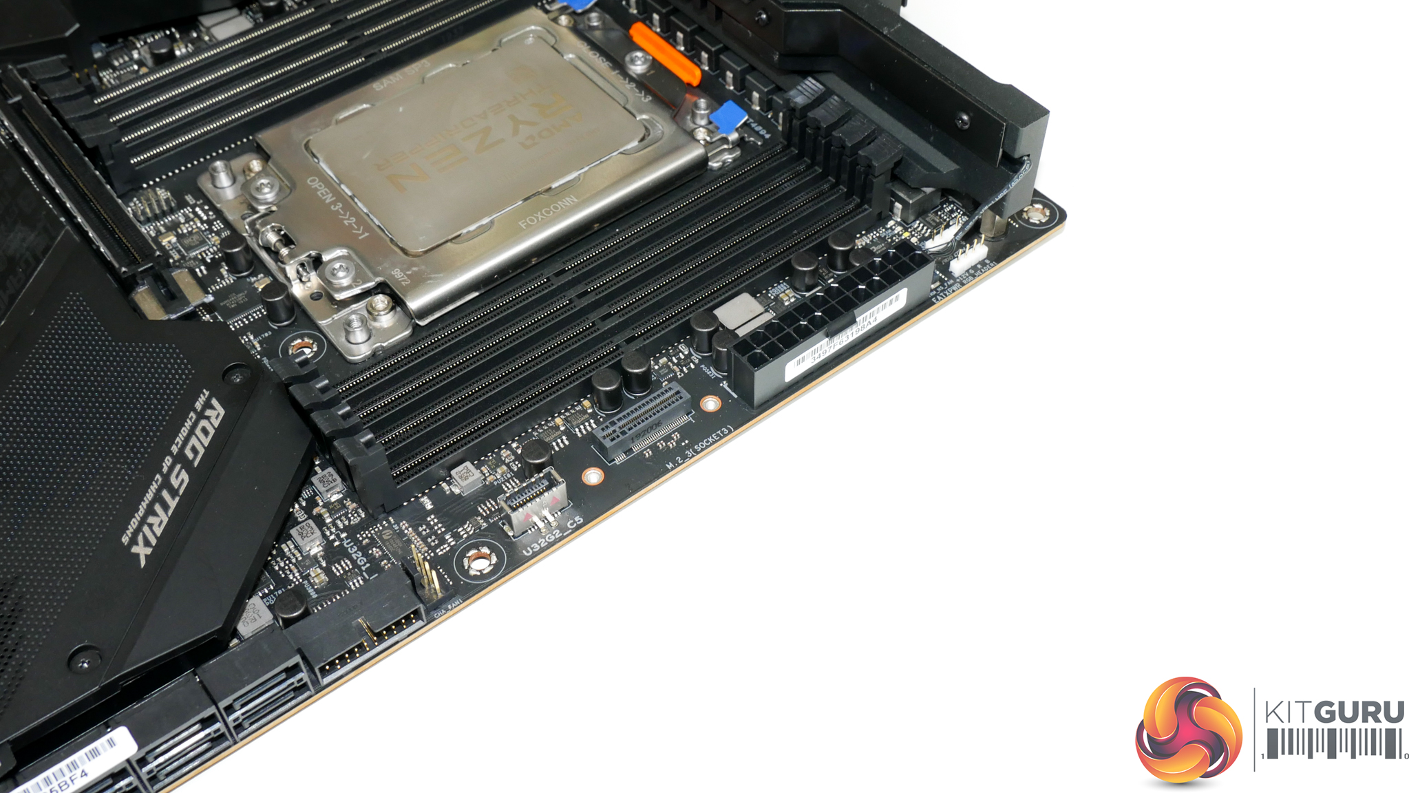
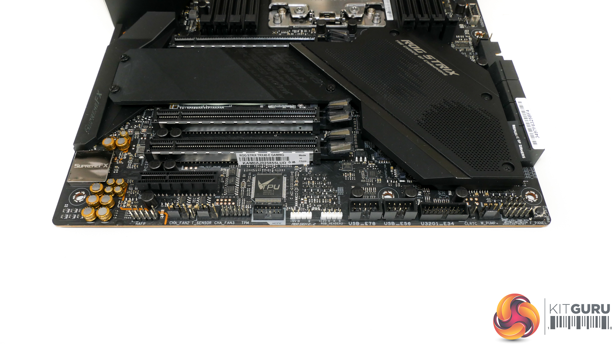
Close to the right-side bank of DIMM slots, you’ll find convenient access to a pair of RGB headers, one of which is the newer Addressable type, a single USB 3.2 Gen 2 Type-C front panel header, and one of the board’s three M.2 slots.
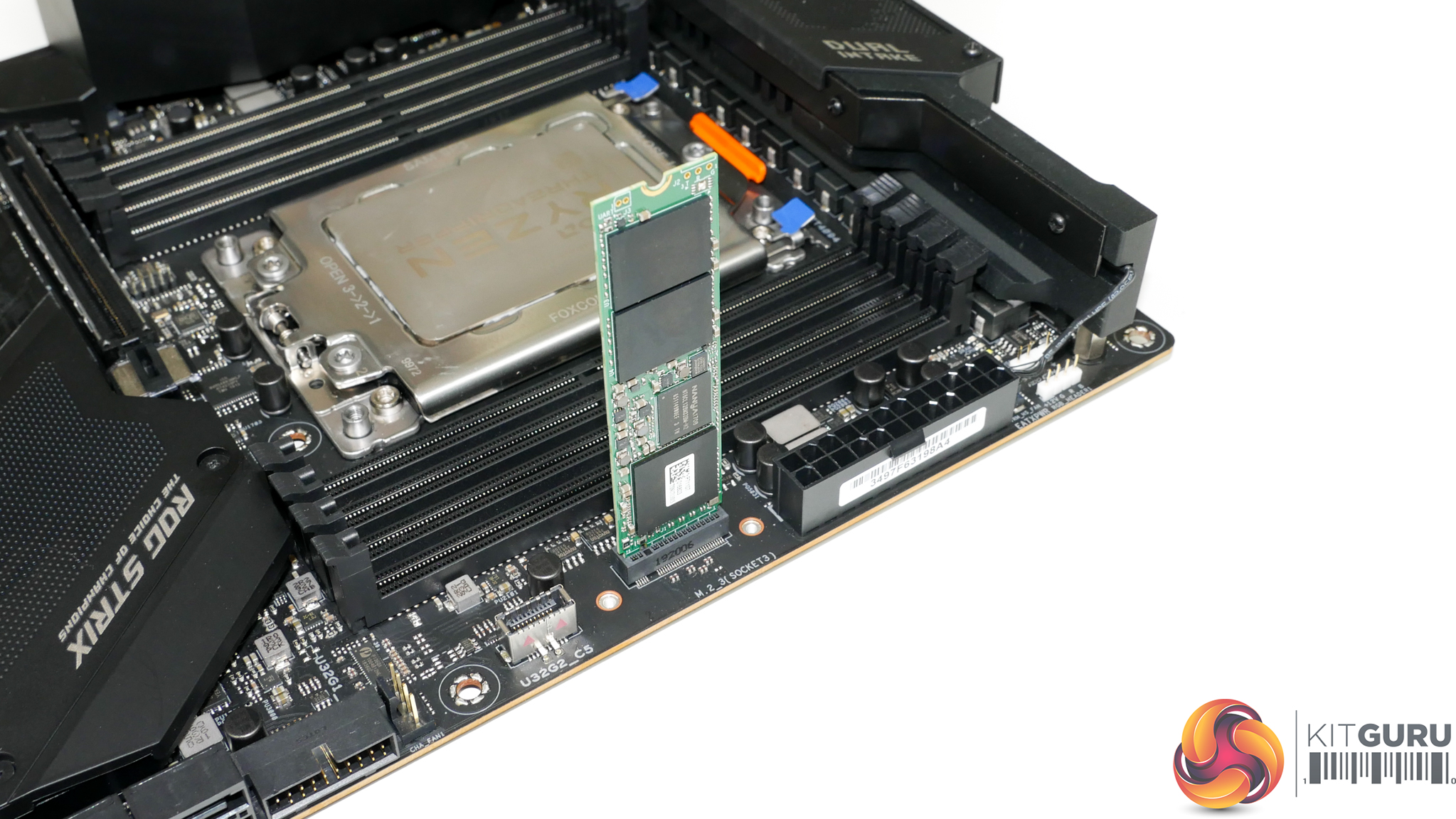
I like the inclusion of this vertical M.2 connector. It’s mounted in a location where interference with other components is unlikely and accessibility is simple, even when the system is fully built. See a deal on a shiny new M.2 SSD? You don’t need to pull out your graphics card and tear the system apart to install that SSD in this location, and that’s a positive. Plus, the vertical orientation is likely to be cooled well by the direct airflow from front chassis fans.
This slot supports M.2 drives up to 110mm in length. TRX40 chipset-fed lanes provide a PCIe Gen 4 x4 link or SATA 6Gbps compatibility. Its bandwidth is not shared with other devices, so you can use this connection at full speed at any time.
Also worth noting is the inclusion of DRAM, CPU, VGA, and BOOT onboard LEDs in a location that is convenient to see when troubleshooting.
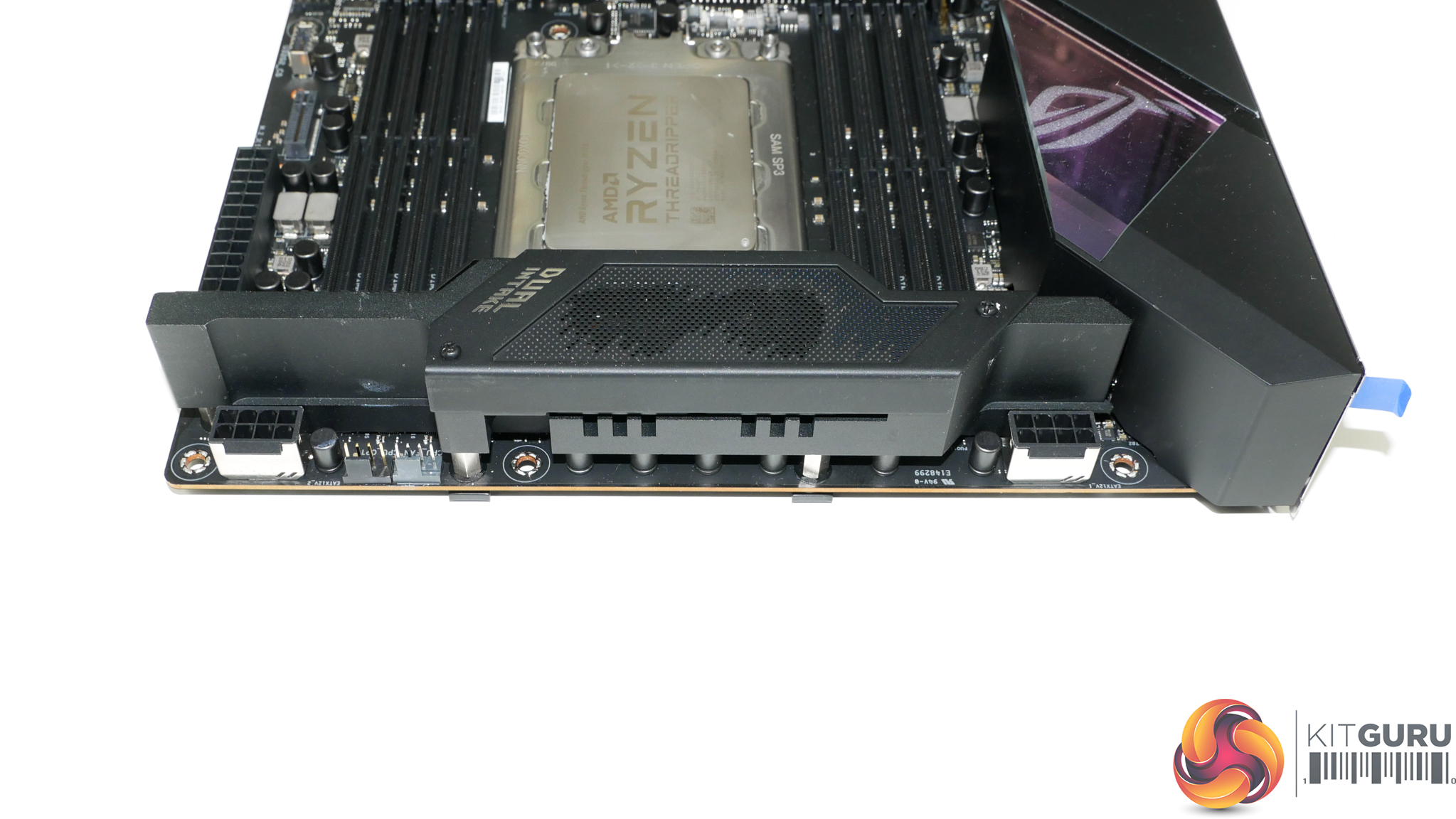
Switching focus to the top edge of the motherboard, we find two 8-pin CPU power connectors hidden on either side of the monstrous VRM heatsink. Dual 8-pins is actually pretty reasonable for sTRX4 motherboards as Threadripper 3000 chips comfortably draw 285W out of the box and can go well over 400W when overclocked.
I don’t mind ASUS’ decision to split these connectors to opposite edges of the motherboard as it may ease the cable routing burdens. Plus, there’s probably an argument for injecting current into the hefty VRM system at opposite ends to reduce voltage drops across the rather long bank of MOSFETs.
Two CPU-focused 4-pin fan headers are located up top, which is a bit stingy in all honesty. There should be a third header dedicated to AIO pump duties as the next nearest header is halfway down the motherboard’s PCB.
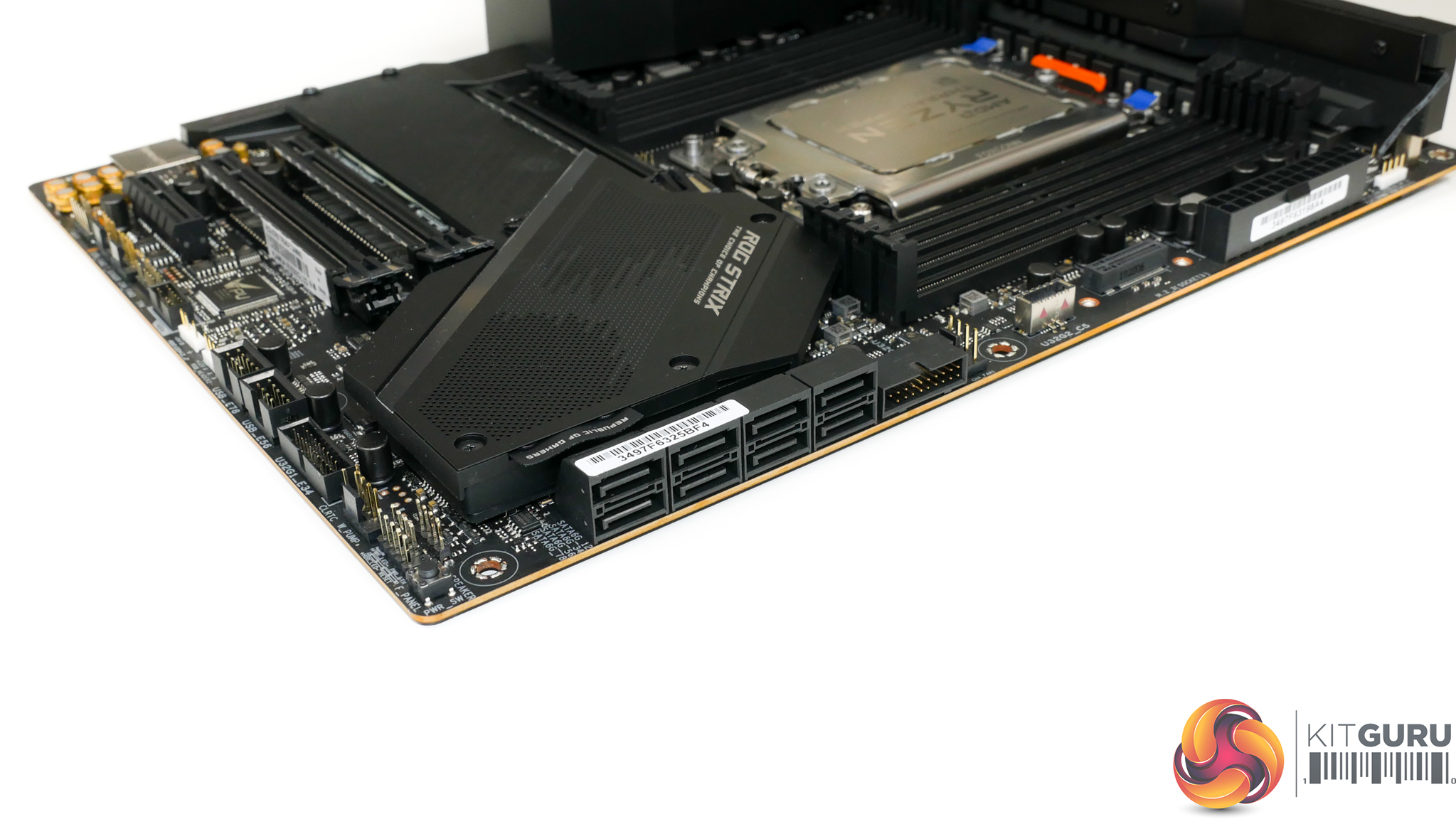
Right-angled SATA ports are found in their usual position and ASUS deploys a total of eight. All of these ports are fed by the TRX40 chipset. I think eight connections for slower SSDs and spinning hard drives is sufficient even for this calibre of motherboard, especially when the triple M.2 capability is factored in. RAID 0, 1, and 10 modes are supported.
Next to the bank of SATA ports is one of the board’s two internal USB 3.1 Gen 1 5Gbps headers. Importantly, this header is connected via an ASMedia ASM1074 hub to the TRX40 chipset. Given that the ASM1074 hub takes a single 5Gbps USB 3.1 Gen 1 lane and multiplies it to four connectors, bandwidth limitations are clear.
If you want to do drive-to-drive copies between external USB 3.1 Gen 1 SSDs, you should be able to run at better speeds by using the alternative USB 3.1 Gen 1 ports on the rear IO.
Nestled at the very edge of the bottom right corner is the onboard power button. This is a feature I like to see included for troubleshooting purposes.
Moving along the set of connectors, you get the second internal USB 3.1 Gen 1 5Gbps header in addition to two internal USB 2.0 headers which is enough for connecting to RGB controllers and AIO pumps. Two more RGB headers, one of which is addressable, are also mounted down the bottom.
As well as the ASUS Node header, there are also three 4-pin fan headers found along the bottom edge. This is good for handling custom liquid cooling pump duties, in addition to lower- or front-mounted chassis fans.
One notable omission that may disappoint some potential buyers is the lack of a Thunderbolt 3 internal header.
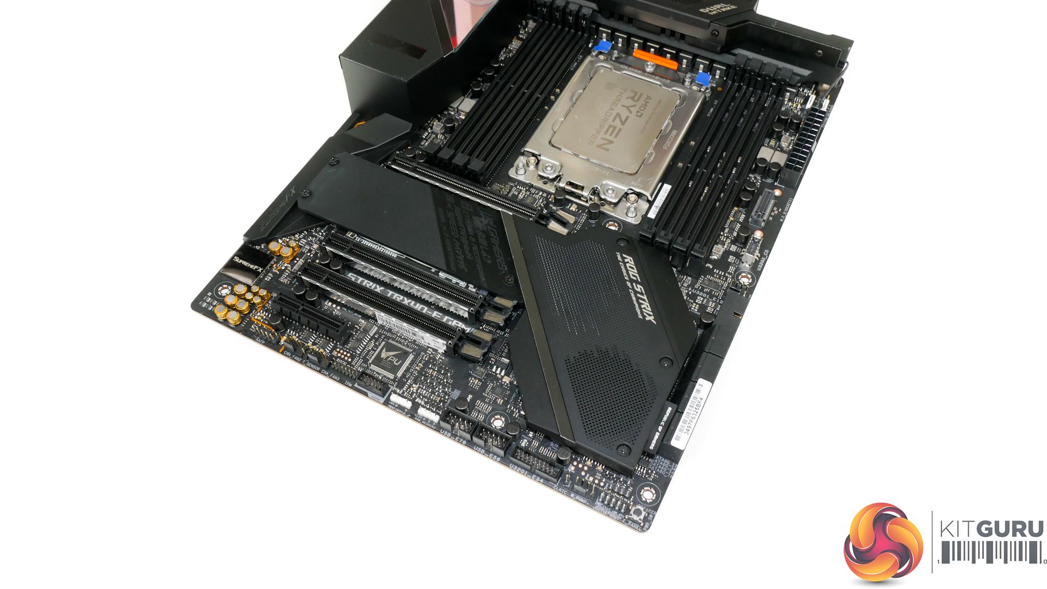
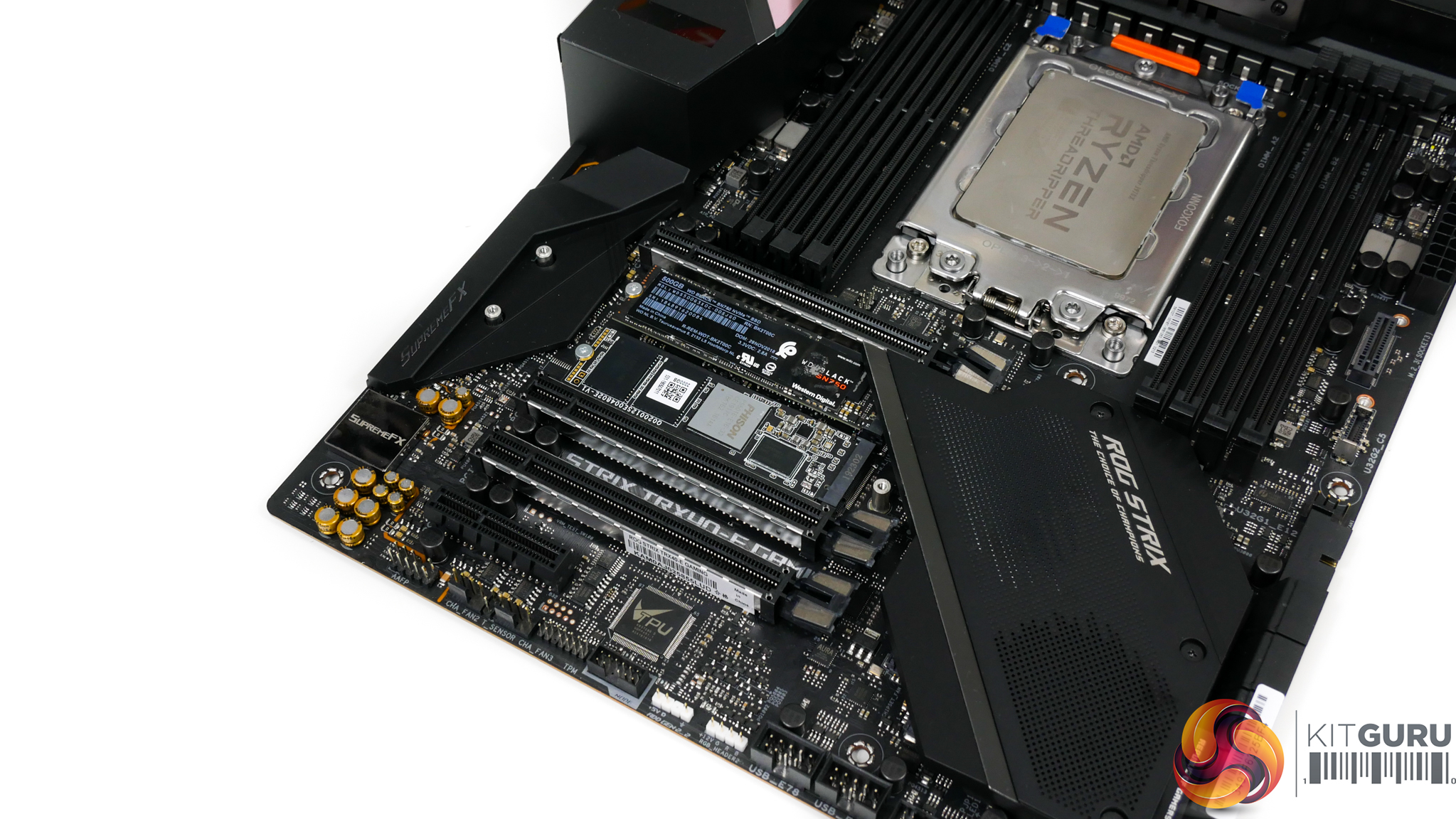
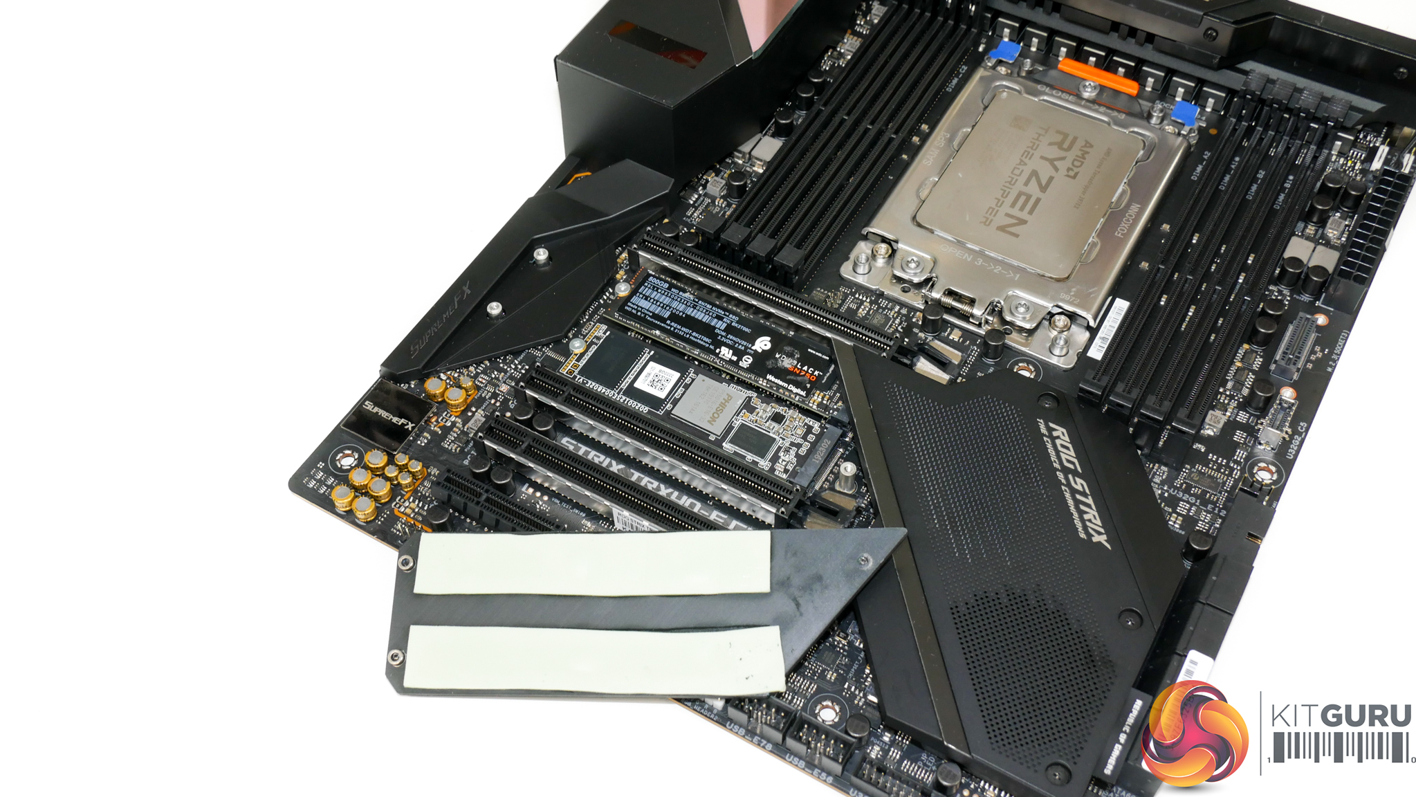
The primary pair of M.2 connectors are mounted beneath a slab of metal that features thermal pads. Both of these slots work with drives up to 110mm long and operate only in PCIe mode with up to 4 lanes of Gen 4 bandwidth direct from a Threadripper 3000 CPU.
The M.2 cooling approach is interesting. ASUS uses a slab of metal to cool both SSDs, meaning that additional heat is dumped into the heatsink. This is likely to cause a challenge for the low-profile design if two high-speed SSDs are being pushed hard simultaneously. With that said, ASUS suggests that the cooling performance is similar to the alternative approach when two drives are used.
ASUS is keen to point out that users with a single SSD installed should benefit from the greater cooling capacity of the physically larger block of metal compared to typical SSD heatsinks on motherboards that are only sized for a single drive.
Positioning of the M.2 slots is the norm but it’s not ideal. This location places the SSDs directly beneath a graphics card that is likely to have an open-air cooler vent hot air directly onto the SSD heatsink. Couple that with the larger heatsink that will draw more thermal energy from the graphics card’s exhaust and M.2 running temperatures are certainly something to keep an eye out for.
Wisely, however, ASUS deploys metal channels close to the chipset heatsink that will direct air from the chipset fan to the M.2 SSD location. That’s a smart move that should help to give an extra burst of coolant air for the SSDs.
Installing an SSD in either of these slots will force the removal of a graphics card. That’s annoying for users who want to install a new drive after building their system. That fact holds especially true for anybody running the GPU in a custom liquid cooling loop.
Thankfully, the vertical M.2 connector can be used for quick-and-easy SSD installs without ripping the graphics card out of one’s system.

In terms of expansion slots, ASUS’ TRX40-E features three steel-reinforced full-length connectors that operate at PCIe Gen 4 x16/x16/x16 bandwidth directly from the CPU. That’ll be a good solution for many Threadripper users who may deploy dual GPUs alongside an accelerator card or a high-bandwidth RAID controller, for example.
The final slot is a closed-back PCIe 4.0 x4 connector that receives its lanes from the TRX40 chipset. This is another good location for high-bandwidth devices such as high-speed NICs or video capture cards. Even more positive is the fact that it doesn’t steal any bandwidth from the main, CPU-connected slots.
Slot count and spacing is not particularly good, especially as ASRock, Gigabyte, and MSI competitors have better strategies at this price point.
With 2.5- or 3-slot graphics cards, you’ll have room for just two of those and nothing else. That’s not so smart. Even using dual-slot graphics cards would only leave you with either the PCIe x4 or PCIe x16 slot spare – not both. Moving the PCIe x4 slot to the second position on the board would be better for dual-GPU users as you could go with two dual-slot cards, plus an x16 slot, plus the x4 slot. However, triple-slot cards would have blocked the PCIe x4 connector in that configuration.
There’s realistically no ideal solution given the varied partnering components and use cases for TRX40 buyers. With that said, the competing vendors’ solutions offer better expansion slot layouts at this price point.
Judging by the layout, I’d say that the TRX40-E Gaming looks to be designed for single graphics card users who also want capability for single-slot, high-bandwidth add-in cards. If you fall into that category, you’re unlikely to have any complaints.
I will, however, say that these configuration headaches are likely to be less annoying than the switch up to the XL-ATX form factor on some competing motherboards and the chassis limitations that brings.
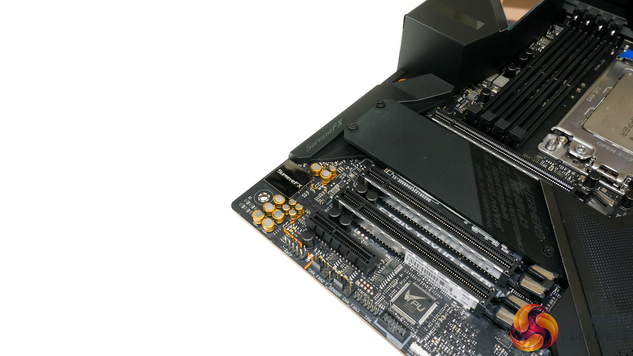
ASUS’ audio solution is built around the SupremeFX S1220 audio codec that is powered by a chipset-fed USB 2.0 port using a Realtek ALC4050H bridge.
Located in close proximity is a Texas Instruments R4580i operational amplifier, in addition to the usual set of Nichicon audio capacitors.
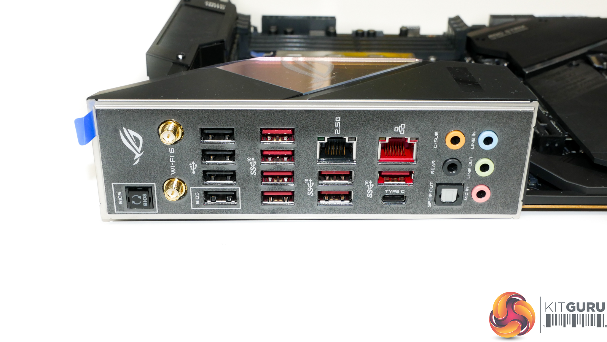
The rear IO is USB central, with a total of four USB 2.0 ports for legacy connectivity and BIOS Flashback duties, and eight USB 3.2 Gen 2 10Gbps connectors. Four of those 10Gbps ports are fed directly from the Threadripper CPU, while the other four (including the Type-C connector made available via an ASMedia ASM1543 logic IC) are delivered through the TRX40 chipset. That means there should be plenty of bandwidth available for high-speed transfers with several USB devices.
Wi-Fi 6 comes from an Intel AX200 adapter and supports data rates up to 1.73Gbps via its 2×2 MU-MIMO connection. Bluetooth 5.0 is also supported. You get standard Gigabit Ethernet from an Intel I211AT NIC, while Realtek’s RTL8125 controller is deployed for 2.5Gbps Ethernet capabilities.
It’s actually a little disappointing to see ‘only’ a 2.5Gbps high-speed NIC included when competing, and cheaper, solutions squeeze a 5Gbps or 10Gbps adapter into the budget. 2.5Gbps is a welcomed upgrade from 1Gbps but it’s realistically a good deal slower than even 5Gbps adapters.
A good way to visualise this is that a 2.5Gbps NIC may give you 250-300MBps when connected to a storage server or NAS. A 5Gbps NIC will give you around 500-or-so MBps, which is about as fast as a SATA SSD. The difference between the two will be evident if you’re a video editor who deals directly with network-attached storage servers. Or if you’re a simulation engineer dealing with large project files over the network. The list of examples goes on. It’s the difference between saturating a SATA scratch SSD in your networked storage server versus leaving half the performance on the table.
Rounding out the rear IO is the usual set of audio connectors, including SPDIF. There’s no clear CMOS button on the rear IO, which is highly annoying for users who are tinkering with their system… or when you get a random crash and failed boot on this still very new platform.
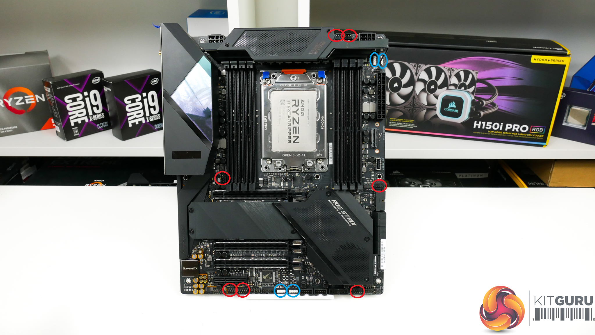
A total of seven 4-pin fan headers are scattered across the board, three of which are within reasonable reach of the CPU zone. The distribution is reasonable and shouldn’t cause any major headaches, other than the lack of an AIO-specific header near to the two top-mounted CPU fan headers.
A Nuvoton NCT6798D-R controller manages fan control and some monitoring duties. I am disappointed to see a complete lack of onboard voltage monitoring points. Whipping out a multimeter to check voltages are fine is a niche scenario, but it’s certainly not unreasonable to request for a board of this calibre with this target audience.
Four LED headers are provided, two of which are standard RGB and the other two are addressable connections. These are split between the top-right and bottom-centre zones on the motherboard in locations that I would consider to be very good.
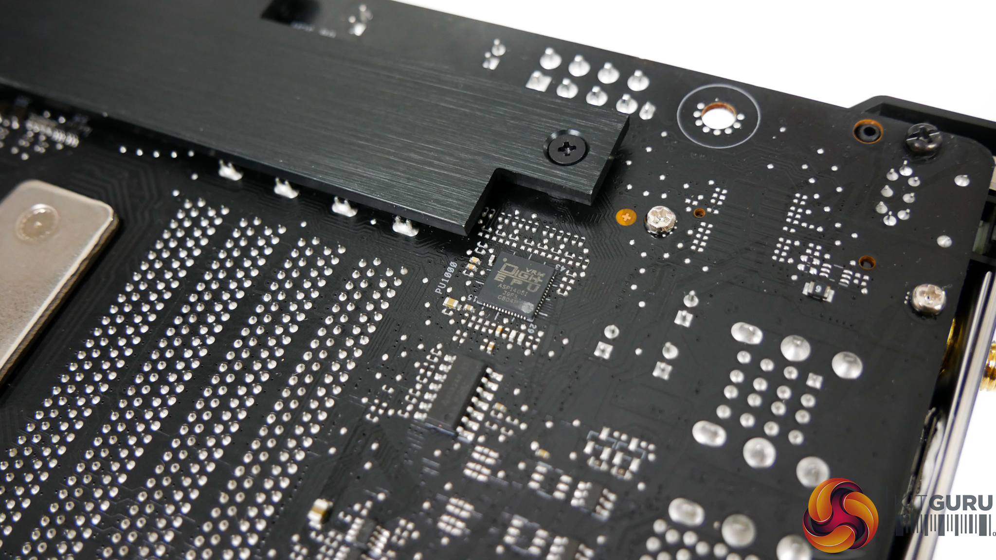
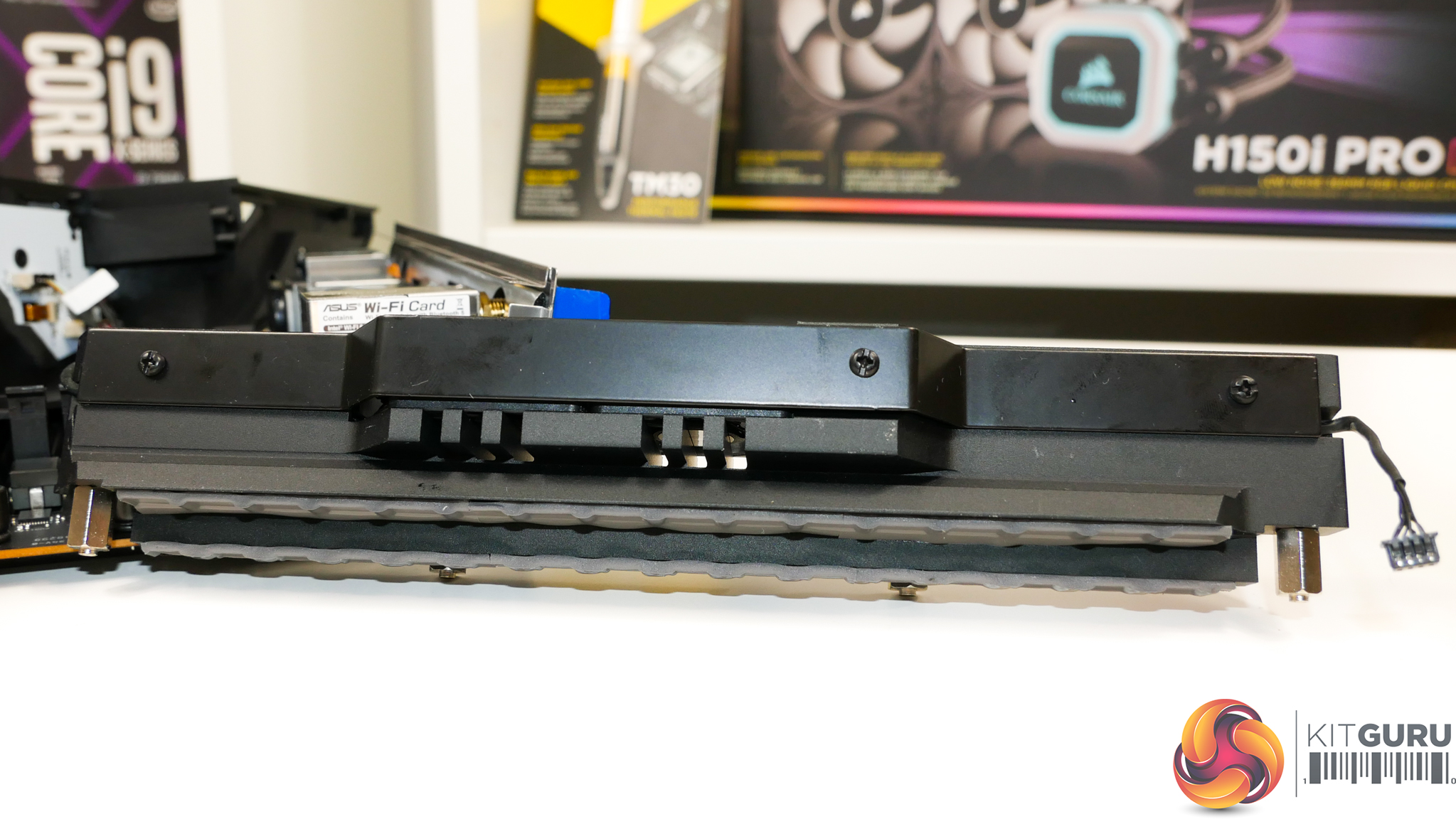
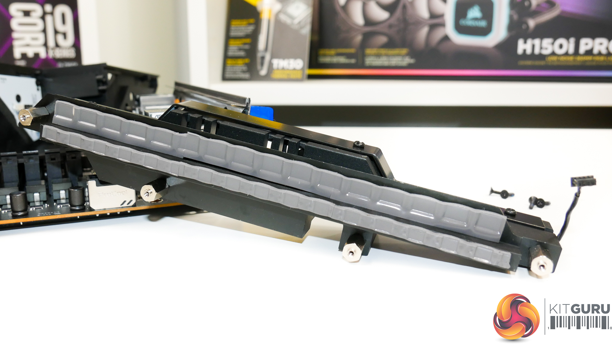
ASUS is using a proprietary ASP1405 PWM controller that is widely believed to be based on the highly competitive International Rectifiers IR35201 8-phase PWM chip. As is typical for ASUS’ recent motherboards, no phase doublers are used and instead one PWM phase is used to drive two sets of electrical components. That rear metal strip is therefore cooling the PCB below the front-side power stages rather than any phase doublers specifically.
ASUS argues that the ‘teamed’ approach of running two sets of electrical components in parallel from one PWM phase removes the added latency of a phase doubler from the equation. However, it also limits the control granularity compared to the higher number of PWM phases provided by phase doublers.
We know that people don’t like to call this a 16-phase solution, but it features 16 sets of power stages that are driven by eight control phases. It’s top-end current delivery performance, which is important when driving high loads to the CPU, is more akin to a 16-phase solution than an eight-phase one.
Either way, at this end of the market and with such high-performance hardware being deployed, the difference between teamed and phase doubled solutions is likely to be relatively small.
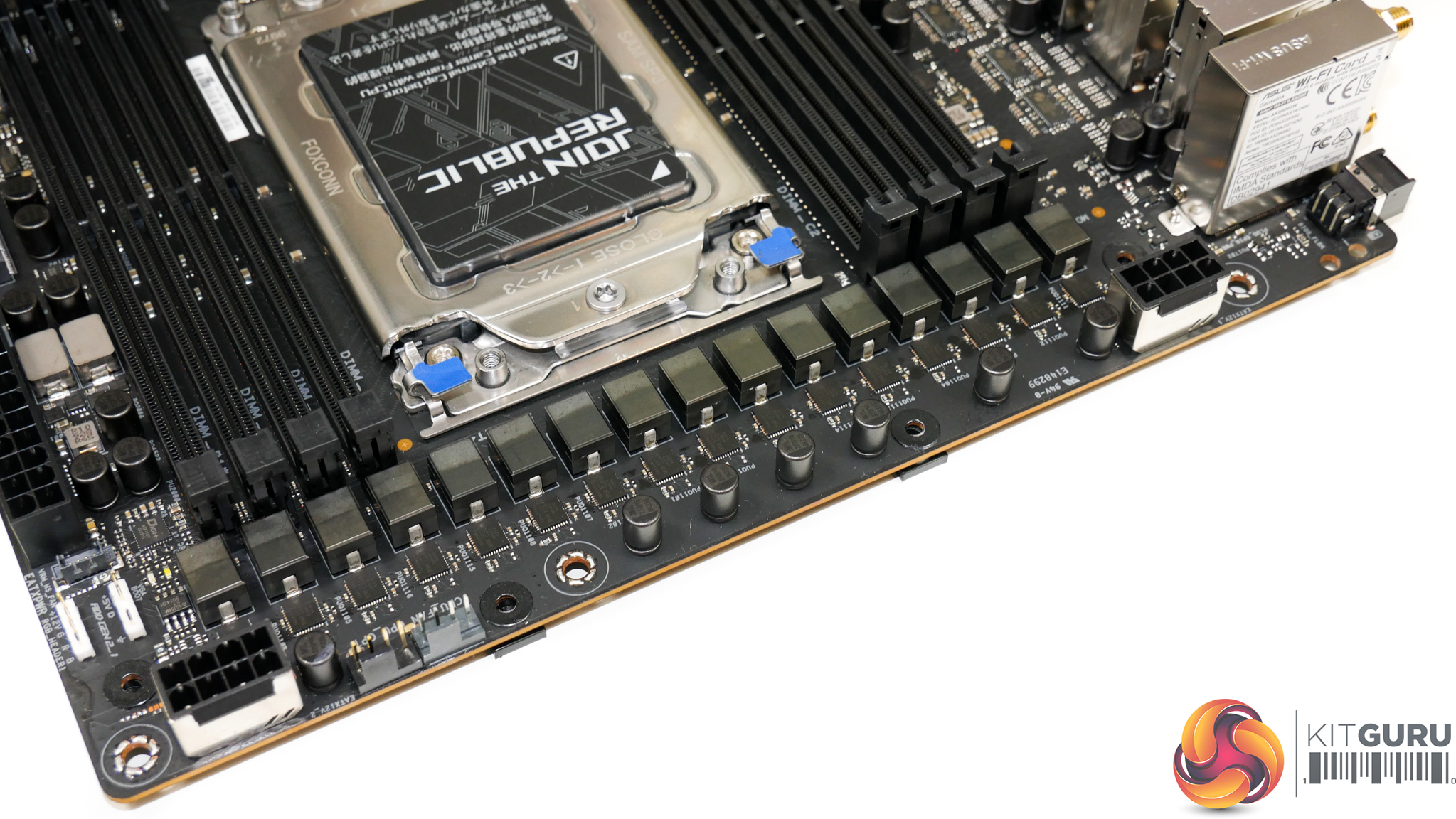
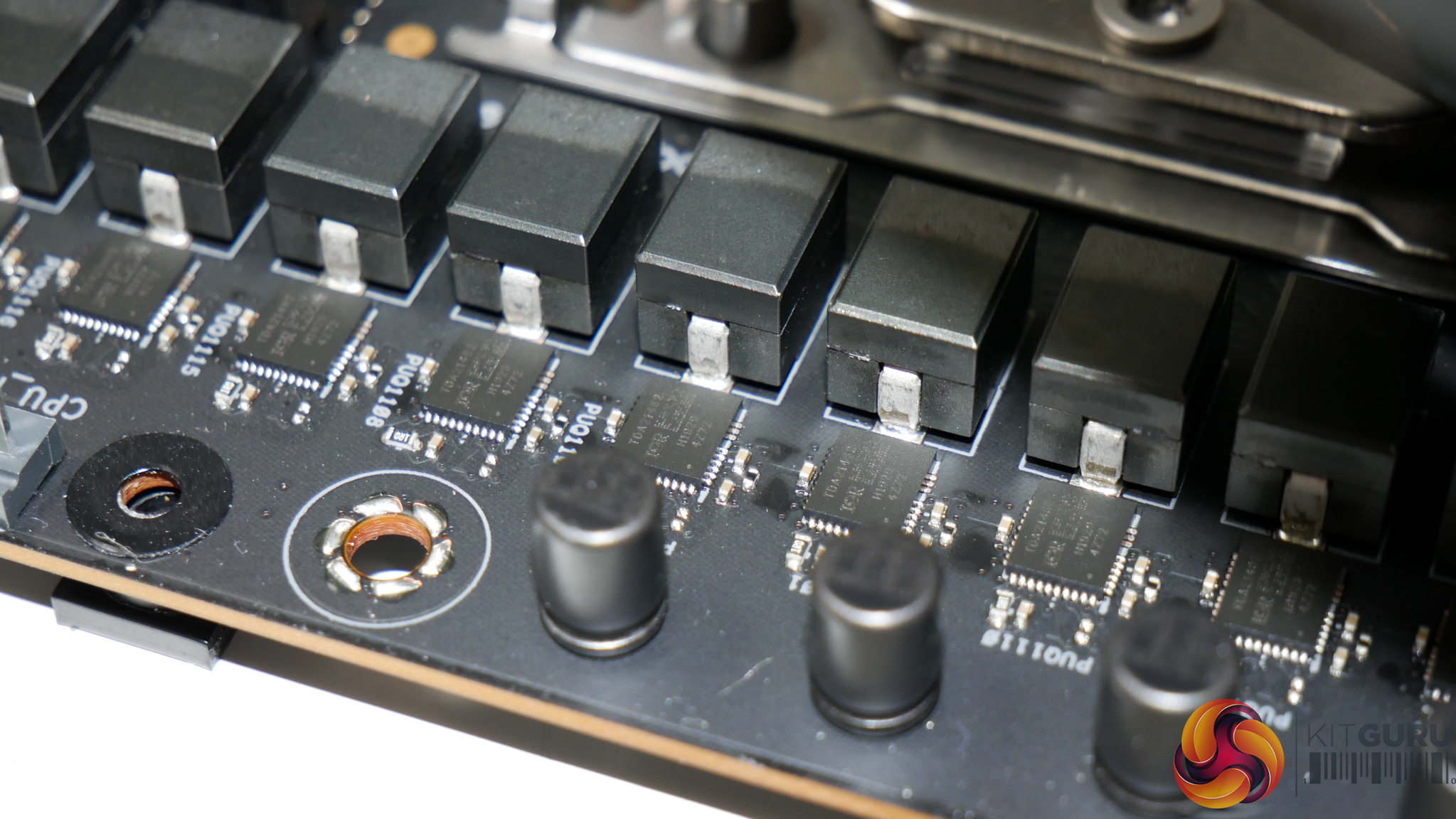
Sixteen Infineon TDA21462 60A power stages are used to drive the sTRX4 processor. These power stages are essentially de-rated versions of the 70A TDA21472 units deployed on higher-end TRX40 boards.
960A of combined current capability is an immense level that will be sufficient even for lofty overclocking goals with future higher core count CPUs.
5K-rated MIL standard capacitors are used for the primary power delivery components. 5K may seem a little meagre for a motherboard of this calibre. However, the higher temperature threshold of typical MIL testing means that working life when extrapolated to real operating temperatures will be perfectly fine, even compared to 10K-rated 105°C alternatives.
As a note, the memory looks to be controlled by a pair of Digi+ ASP1103 controllers, one of which is located near to each DIMM bank.
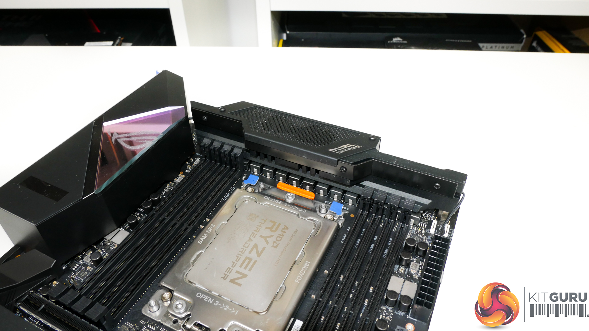
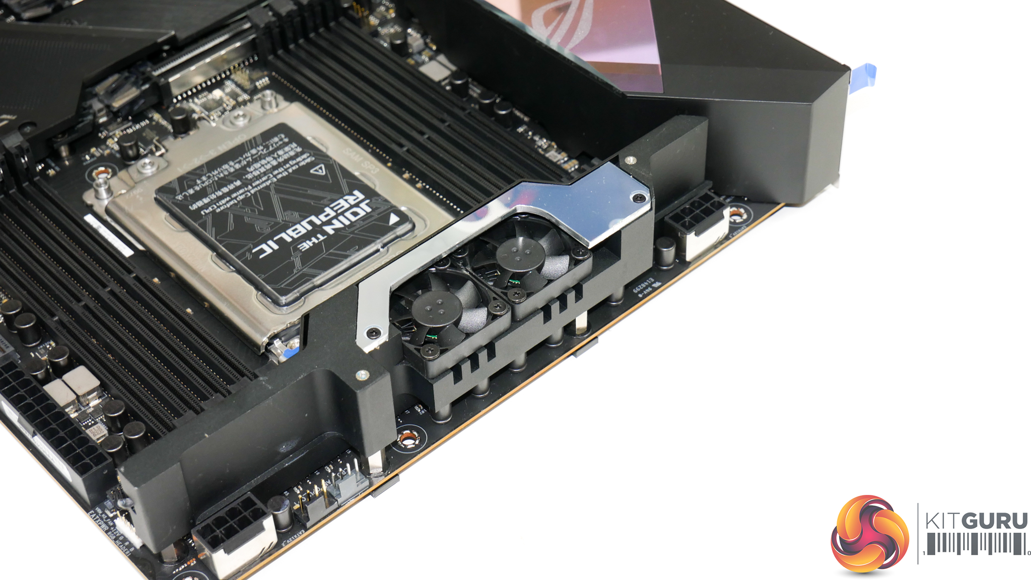
ASUS uses a massive, tiered heatsink to cool the sixteen sets of VRM components, including the chokes via contact and through a thermal pad. This heatsink is a hybrid type design that uses a sizeable slab of metal for thermal capacitance and stacked fins to increase the surface area for longer, steady-state heat dissipation.
A pair of 30mm PWM-controllable fans are mounted on the VRM heatsink. This had me slightly disappointed at first as there realistically isn’t a need for them if ASUS has done a good enough job with the VRM component selection and heatsink design. Thankfully, ASUS sets the fans by default to remain idle up until 60°C VRM temperature – a figure and fan speed curve that can be controlled in the UEFI.
This is a smart move as it means that the VRM cooling remains silent when the MOSFET temperatures are reasonable and there’s extra cooling capacity available when it may be needed for heavy overclocked scenarios.
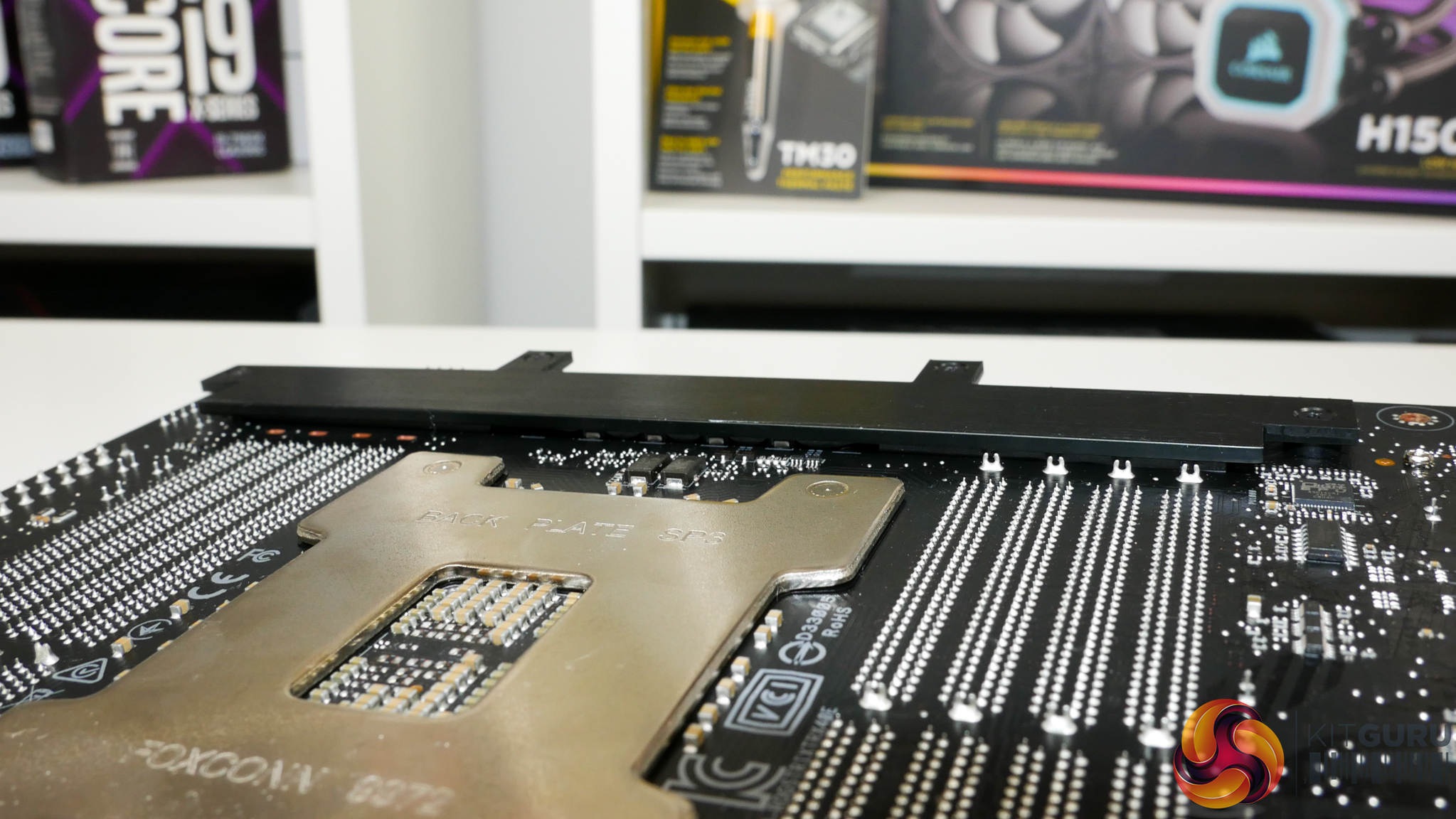
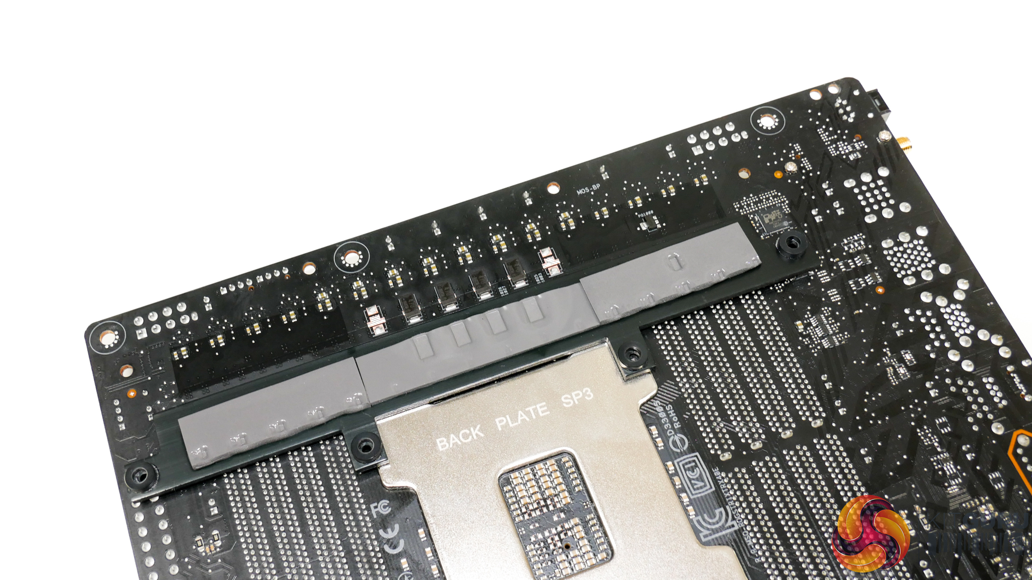
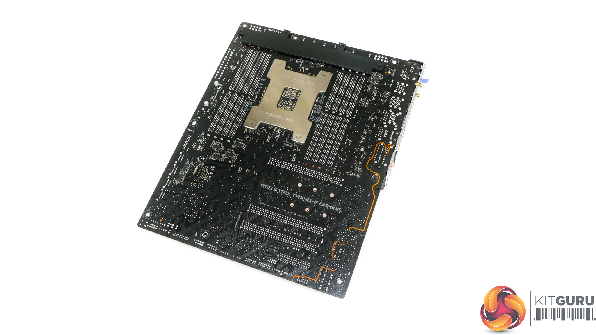
The rear strip makes direct contact with the motherboard PCB via a thermal pad. There is no power delivery logic in this location, so its job is to extract heat that soaks through the PCB from front-side mounted power stages.
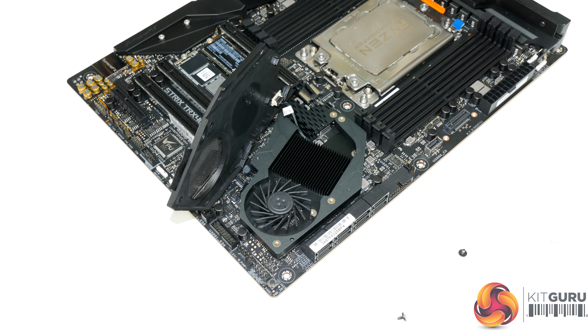
ASUS’ 40mm controllable chipset fan sits atop a metal cooling plate that features ample fins to dissipate heat from the TRX40 silicon. The fan is an open-rotor radial design that needs to force air across the well-sized fin stack in order to dissipate thermal energy effectively.
Incidental airflow for the radial fan is also routed towards the M.2 SSDs nearby, which is a smart move by ASUS.
Positioning of the chipset fan is rather smart as ASUS has made effort to position the blower as far away from a top-slot graphics card as is reasonably possible. This means that the small fan will be able to ingest air from the cool stream driven in by front chassis fans, with a lower amount of interference from the exhaust air exiting a hot graphics card cooler.