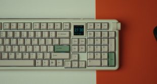

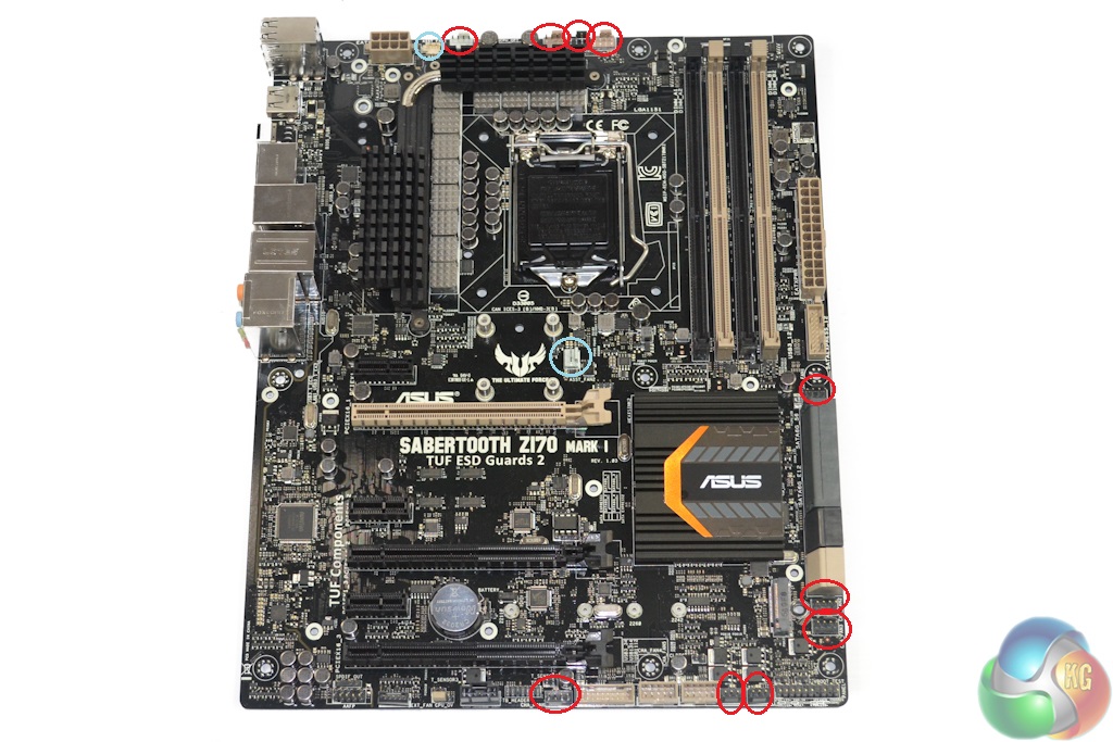
The Asus Sabertooth Z170 Mark 1 motherboard conforms to the standard ATX form factor. A largely black and grey colour scheme that is accompanied by brown and beige highlights is difficult to analyse.
Aesthetic preference is a very subjective topic, however the dark Thermal Armour covering and black port blocking pieces should help to create a good-looking, dark build.
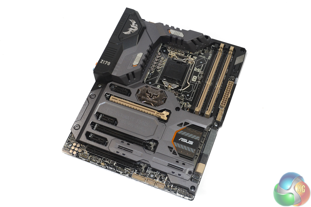
The job of Asus' front-side Thermal Armor plastic cover is to segregate primary areas of heating. The motherboard's PCB is completely segregated from a hot graphics card thus alleviating a significant heat affected zone in close proximity to the board's graphics-housing PCIe slot.
With thermal segregation via a good resistor of heat such as plastic comes the challenge of extracting thermal energy away from the motherboard PCB. Two fan mounts are cut into the Thermal Armor cover, and their function seems to be of importance.
The 35mm fan positioned below the CPU socket will feed (relatively) cool air beneath the plastic cover leading for the heat-absorbing coolant to flow down towards the lower board section, away from the primary temperature-sensitive expansion cards. The 40mm fan mounted in the rear IO section pulls clean air into a dedicated area that is used to cool the motherboard's VRM components.
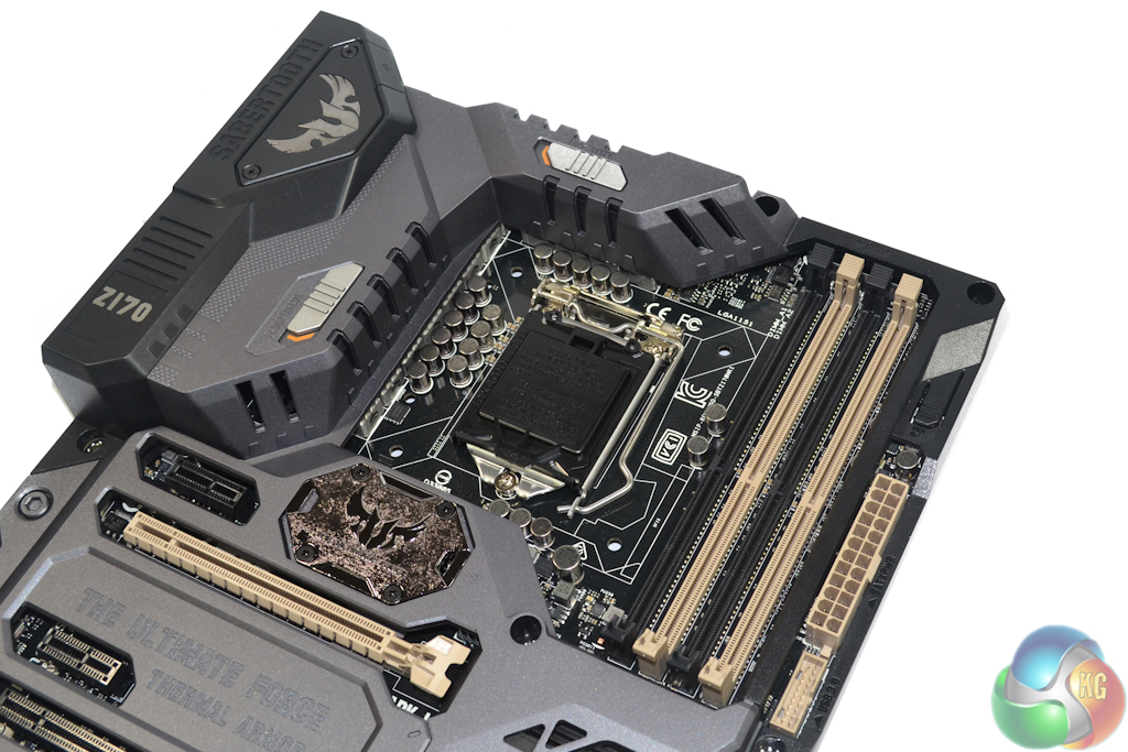
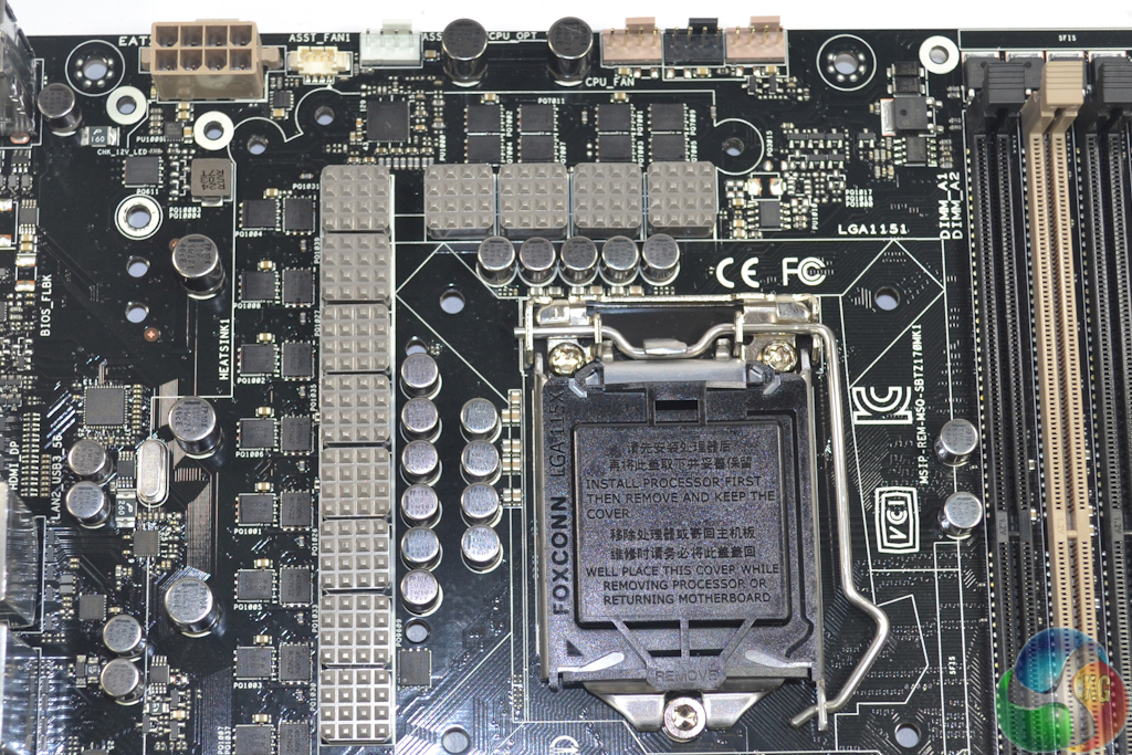
Intel's LGA 1151 CPUs can be installed alongside up to 64GB of DDR4 memory in dual-channel operation. Asus says that the single-latch DIMM slots are able to run memory at up to 3733MHz via overclocking, however higher frequencies may be plausible with the correct BIOS, memory kit, and CPU combination.
Spacing between the CPU socket and DIMM slots is decent, however do not expect to bypass interference if you want to use a large CPU air cooler with excessively tall memory modules, such as KLEVV's Cras series DDR4. A Noctua NH-D14's fin array completely overhangs the first DIMM slot, and that does not account for the front fan's necessary clearance.
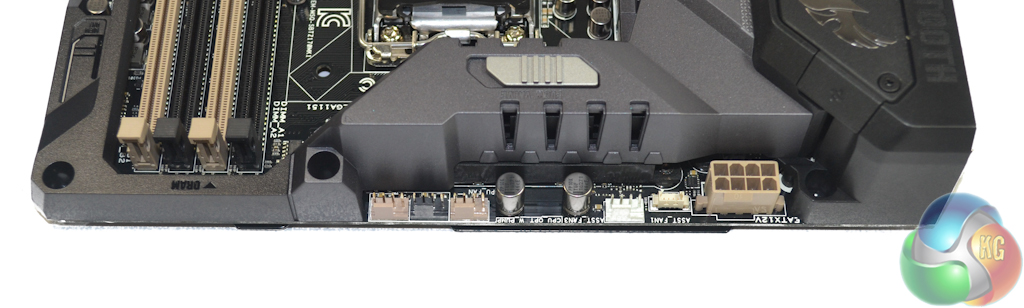
As well as the 8-pin CPU power delivery connector, a total of five fan headers are found along the board's upper edge. Two 4-pin headers handle CPU fans, one next to that pair is dedicated for AIO watercooling pump duties (where 100% speed operation is important), and the two remaining handle ‘Assistant' fan duties.
Of those two ‘Assistant' fan headers, one uses a mini laptop-style connector and is explicitly allocated for controlling the 40mm rear IO intake fan.
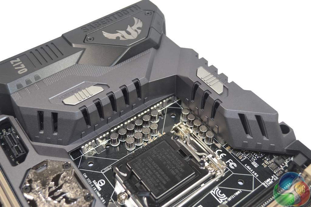
Thermal Armor features a pair of flow valve switches located in the VRM heatsink area. Opening or closing these valves allows for adjustments to the way in which the VRM circuitry is cooled. With a down-draft CPU cooler, for example, opening the flow valves will allow incidental airflow to entire the MOSFET heatsink area and provide cooling.
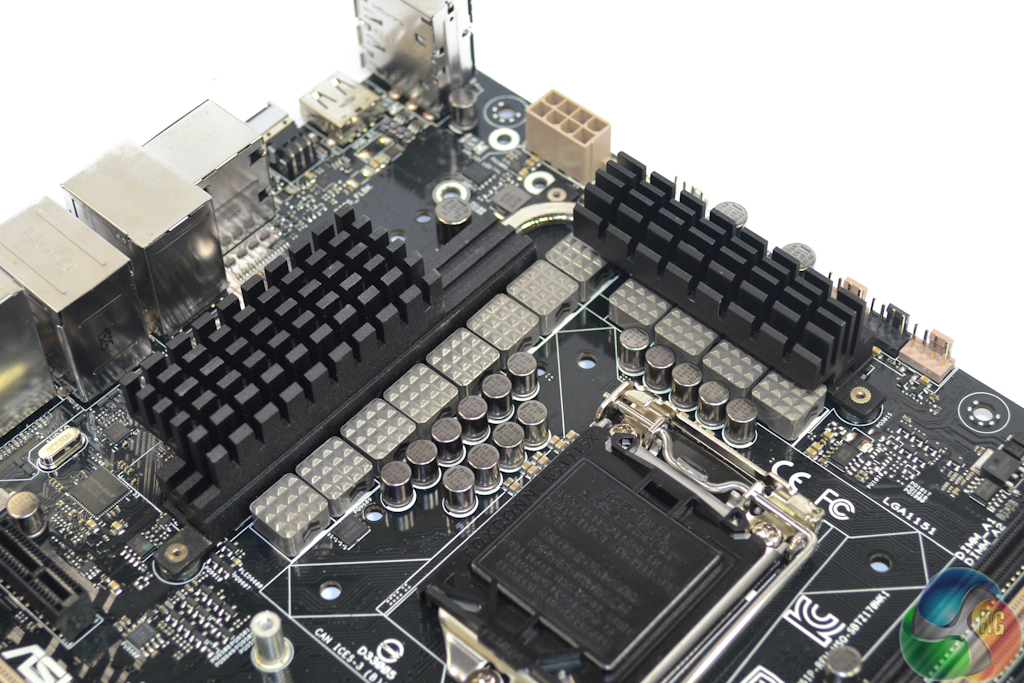
A hefty pair of metal heatsinks, which are connected via a heatpipe, cool MOSFETs for the twelve power delivery phases. I am fond of the heatsink design – there are no gimmicky styles in the form of marketing features, but instead a smart fin layout which should permit for sufficient heat transfer.
The primary power delivery components include 10K-rated ‘TUF Ti-caps', 40A-rated alloy chokes, and ‘TUF MOSFETs'. Asus claims that enhanced durability is achieved by the alloy chokes operating at lower temperatures, the capacitors being able to withstand higher operating temperatures, and the MOSFETs having a lower resistance.
Managing the power delivery system is a Digi+ ASP14051 PWM controller. Twelve ON Semiconductor 69A-rated NTMFS4C06N MOSFETs (marked 4C06N RCNQZ) and a further dozen 52A-rated NTMFS4C09N MOSFETs (marked 4C09N RCD4H) form the front-mounted high- and low-side MOSFET configuration. An additional eight NTMFS4C06N MOSFETs are found on the motherboard's rear side.
Ten International Rectifiers IR3535M MOSFET drivers are utilised. We also identified International Rectifiers IR3595 controllers in the vicinity of the VRM components.
The CPU is fed by eight power phases while the integrated GPU receives the remaining four. Asus' Digi+ ASP1103 controller is used to manage two-phase the memory subsystem.
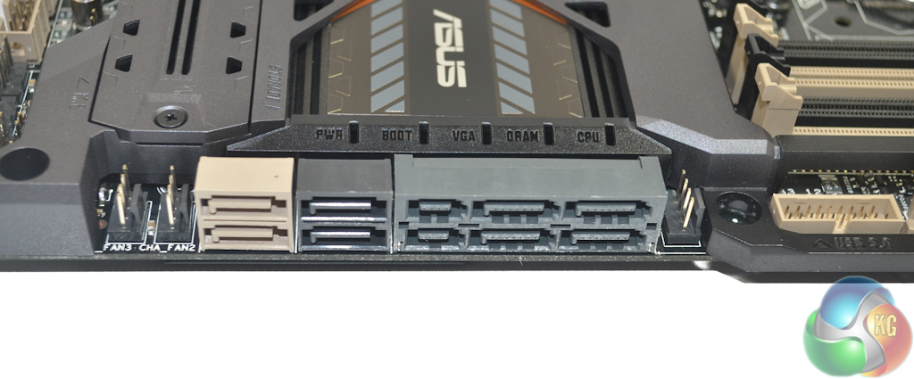
A total of eight SATA 6Gbps ports are found on the board, two of which originate from the ASMedia ASM1061 controller and should be reserved for slower storage devices. Four of the chipset-fed SATA 6Gbps ports double up as a pair of SATA-Express connectors which have found resurgence thanks to front panel USB 3.1 devices.
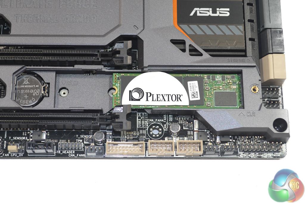
PCIe and SATA SSDs up to 110mm in length can be installed in the board's covered M.2 slot. Four PCIe Gen 3 lanes from the Z170 chipset provide support for transfer rates of up to 32Gbps, however the PCH's flexible IO ports can switch the operation to a SATA 6Gbps connection.
The M.2 SSD is installed beneath a dedicated cover in Thermal Armor. This design helps to segregate an SSD from other heat sources (and hides ugly green PCBs) but it will also cause the drive to heat up significantly due to minimal incidental airflow. This could cause issues for drives prone to thermal throttling, such as Samsung's modern NVMe M.2 SSDs.
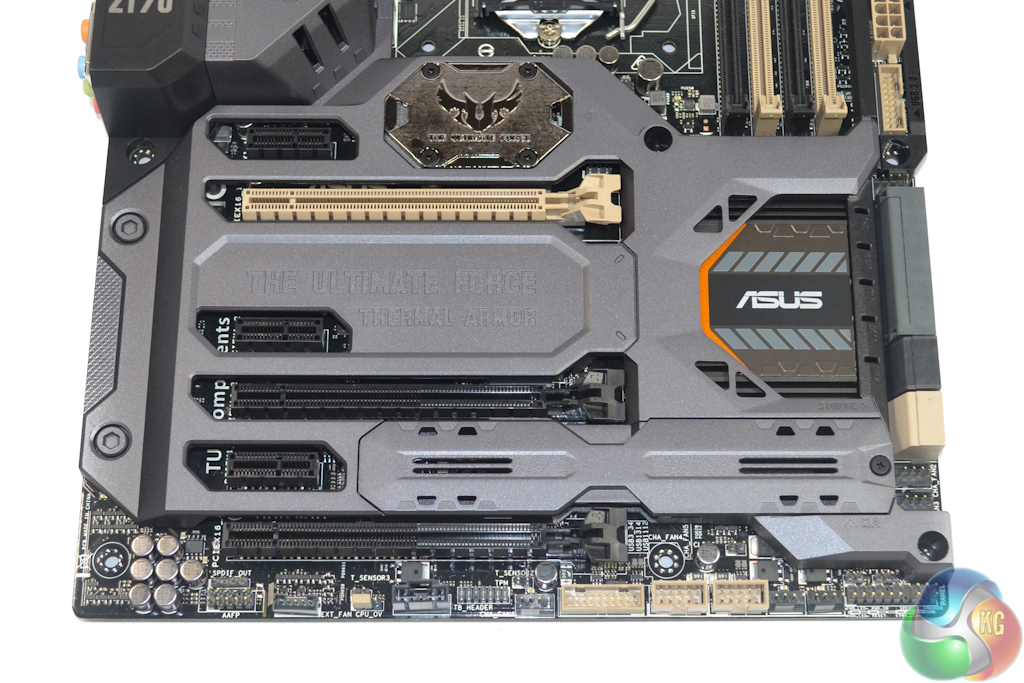
Up to two cards are supported in SLI or three cards in CrossFire due to its less stringent bandwidth requirements. The upper two full-length PCIe slots receive their lanes directly from the CPU and can split them as x16/x0 for a single graphics device, or x8/x8 for a pair of GPUs.
The bottom full-length slot receives four PCIe 3.0 lanes from the Z170 chipset and should be reserved for use with devices such as a PCIe SSD or RAID card rather than potentially bottlenecking an AMD GPU. Using the slot in its PCIe x4 mode renders two of the SATA 6Gbps ports inoperable, however the alternative PCIe x2 mode retains complete SATA port operation.
Spacing between the slots is smart – two dual-width graphics cards can be installed with a cooling gap between them. And that is while also leaving room for an additional high-bandwidth device in the lowermost slot.
The remaining three PCIe 3.0 x1 slots can be used for supplementary devices such as WiFi adapters and sound cards.
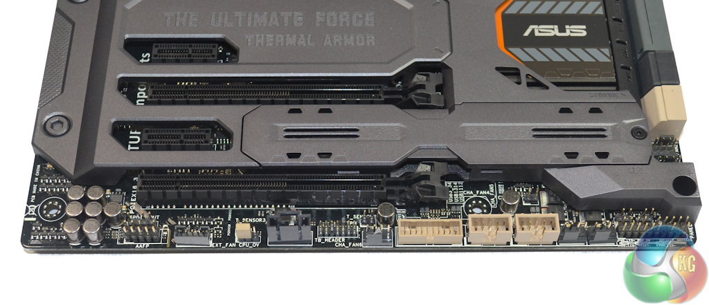
The expected array of front panel ports is found along the lower edge. In addition to those common connectors is a second internal USB 3.0 header (the other is next to the 24-pin port) and multiple fan connections. There's also the EXT_FAN header for connecting an add-on fan control hub.
While the chipset heatsink features a number of activity LEDs, there is no two-digit debug display on the motherboard which is disappointing. A simple two-digit debug display is useful for troubleshooting failed system boots or overclocks.
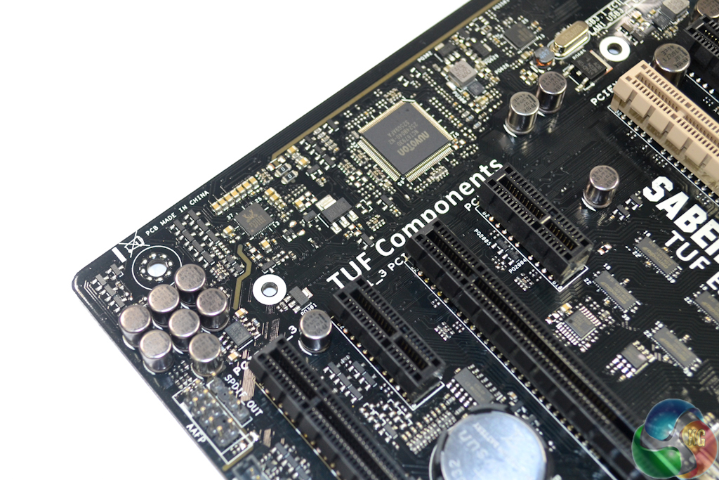
Asus' audio system resides around the popular Realtek ALC 1150 codec. Segregated paths and multiple capacitors are used to minimise signal interference however there is no explicit EMI shielding for the audio chipset. A Texas Instruments R4580i op-amp is also utilised.
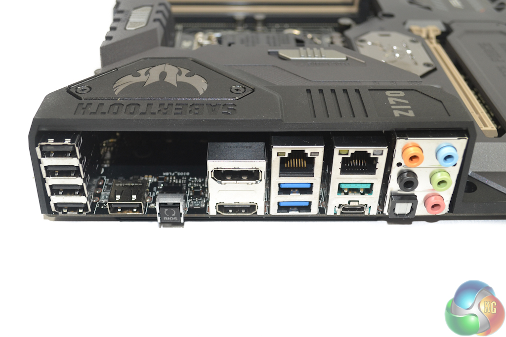
A stack of four USB 2.0 ports is useful for connecting low-bandwidth devices such as a mouse and keyboard. Next to that bank of connectors is the BIOS Flashback button. Some users may be disappointed to see a PS/2 header omitted as it can be useful for troubleshooting measures (especially when using the Z170 chipset with Windows 7).
DisplayPort 1.2 and HDMI 1.4b connectors provide video output via an ASMedia ASM1442K switch. The former supports a 4K 60Hz output from the Skylake chip's onboard GPU. Gigabit Ethernet ports are provided via Intel's I219V and Realtek's RTL8111H chipsets.
Two 5Gbps USB 3.0 Type-A ports are fed from the Z170 chipset. The neighbouring 10Gbps USB 3.1 ports (one Type-A and one Type-C) are provided via an ASMedia ASM1142 chipset, as well as EtronTech's EJ179V and EJ179S logic ICs for Type-C operational capabilities.
The omission of an outright clear CMOS button on the rear IO section will irritate users who enjoy tweaking their fully built system.
No less than a dozen fan headers are distributed around the board, however two of those are specifically allocated duties of controlling the supplied Thermal Armor fans. Asus' UEFI and OS software tools allow a good level of speed control. Nuvoton's NCT6793D and a TUF ICe chipsets manage fan control and monitoring duties.
On the topic of monitoring, I would have liked to see some onboard voltage reading points. This would have provided an extra layer of reliability by taking controller reading errors out of the equation when manually recording voltages or troubleshooting.
Thermal Armor Features
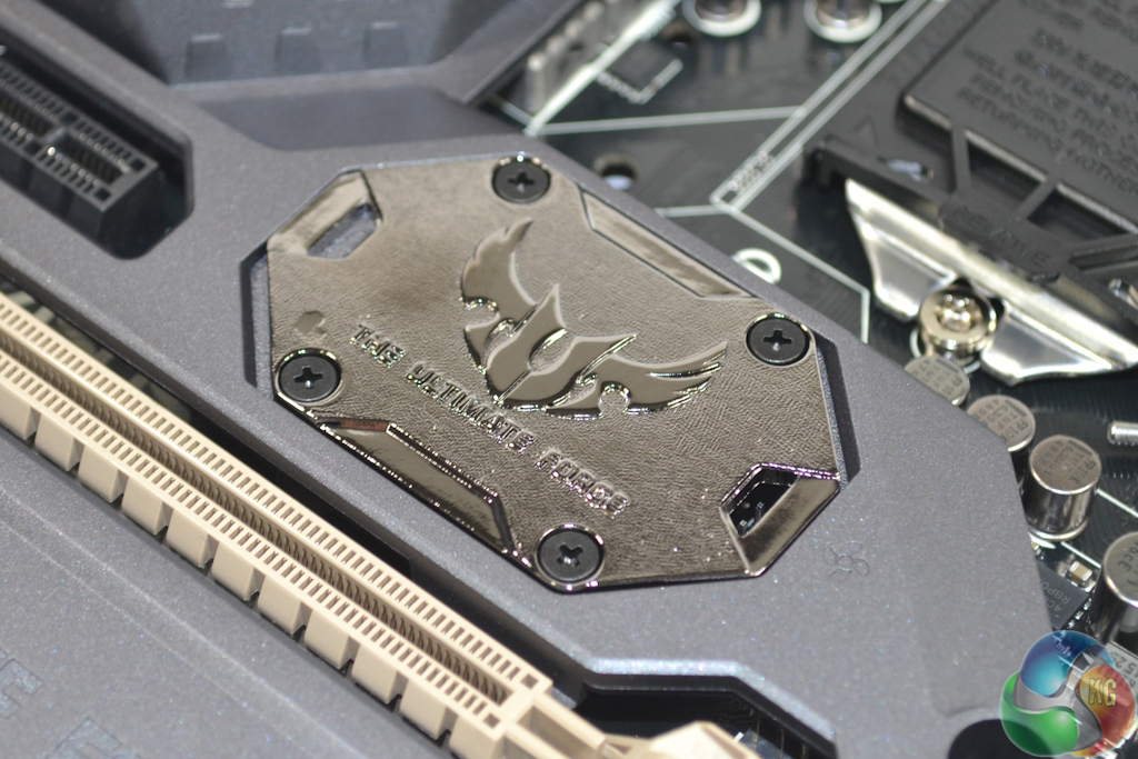
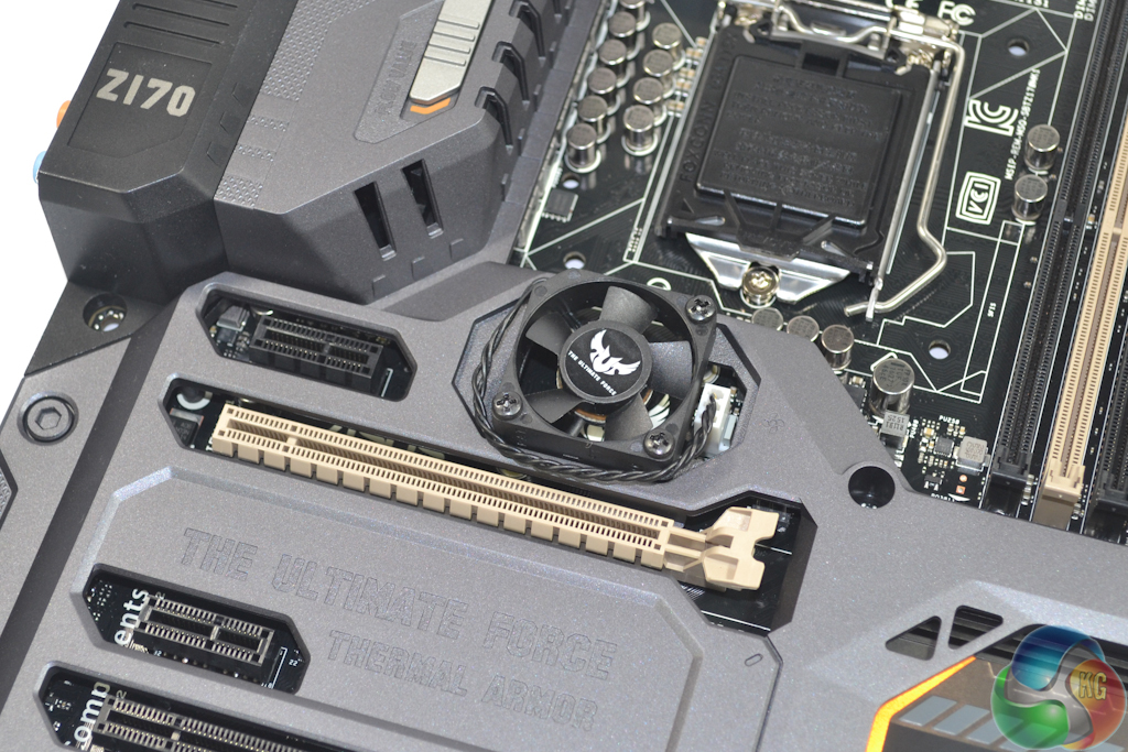
After the slightly awkward removal of a metal covering plate (which can then be used to create a military-style dog tag keyring), the 35mm fan can be installed. This fan forces air beneath the Thermal Armor in order to remove heat from the motherboard PCB and exhaust it towards the bottom of the board.
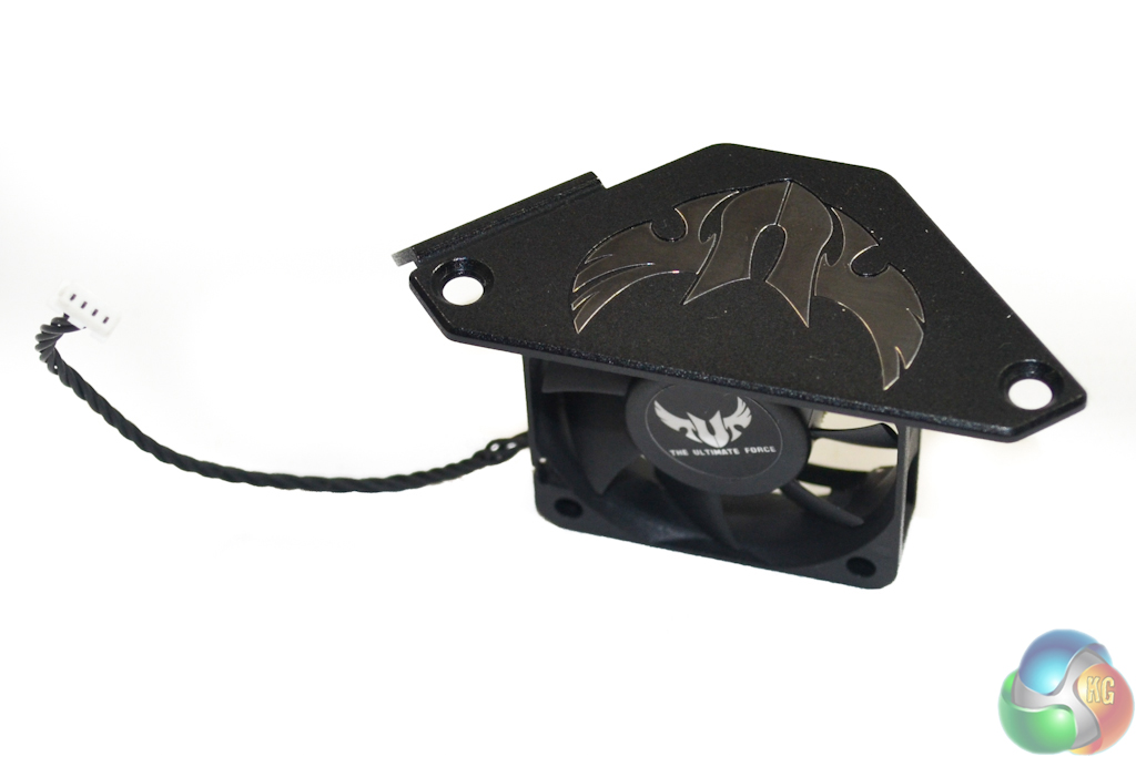
The 40mm VRM fan is attached to a removable plastic covering for ease of installation.
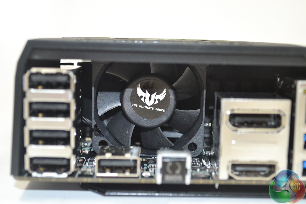
Slotting this fan back into position allows the VRM heatsinks to be fed with clean, cool air.
By default, both of the motherboard fans get extremely loud when a full load is applied. There are, however, functions in the UEFI and OS software to control their operating speed and characteristics.

Removing the Thermal Armor shaped plastic covering is straightforward. Despite being a relatively simple procedure, one's CPU cooler and graphics card will have to be removed meaning that cleaning below Thermal Armor will require an entire system strip-down. Potentially splitting Thermal Armor into two discrete sections would aid the simplicity at which the lower half can be removed for periodic cleaning.
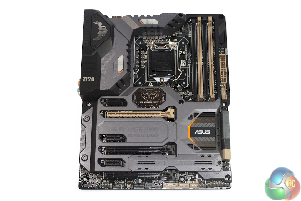
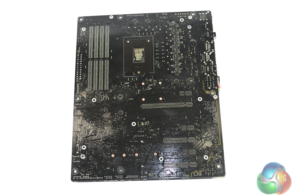
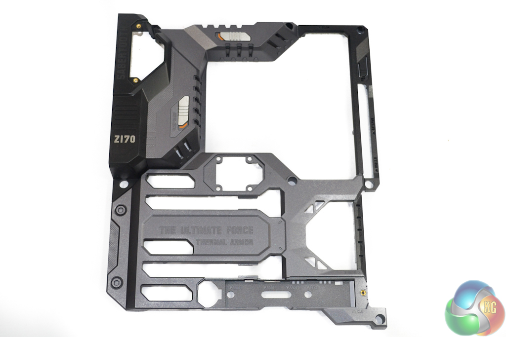
Asus' metal – TUF Fortifier – backplate is used to enhance motherboard rigidity and it does so very well. While its function may not be so apparent at first thought, having a heavy air cooler hanging from the CPU socket creates a large amount of bending stress on the motherboard's PCB. The metal plate helps to increase the motherboard's stiffness, thus reducing the strain caused by a heavy CPU cooler.
A thermal strip also draws heat away from a set of rear-mounted MOSFETs and transfers it to what is effectively a large metal heatsink.