

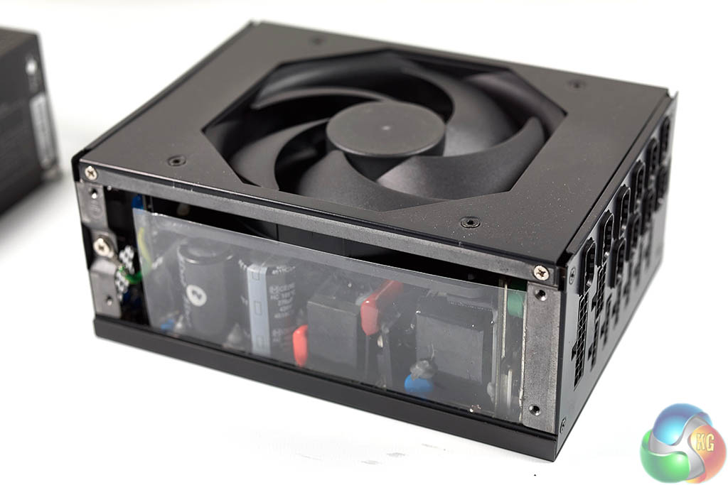
The outer aluminium shell is the first thing to remove. Then we can get a closer look at the components inside.
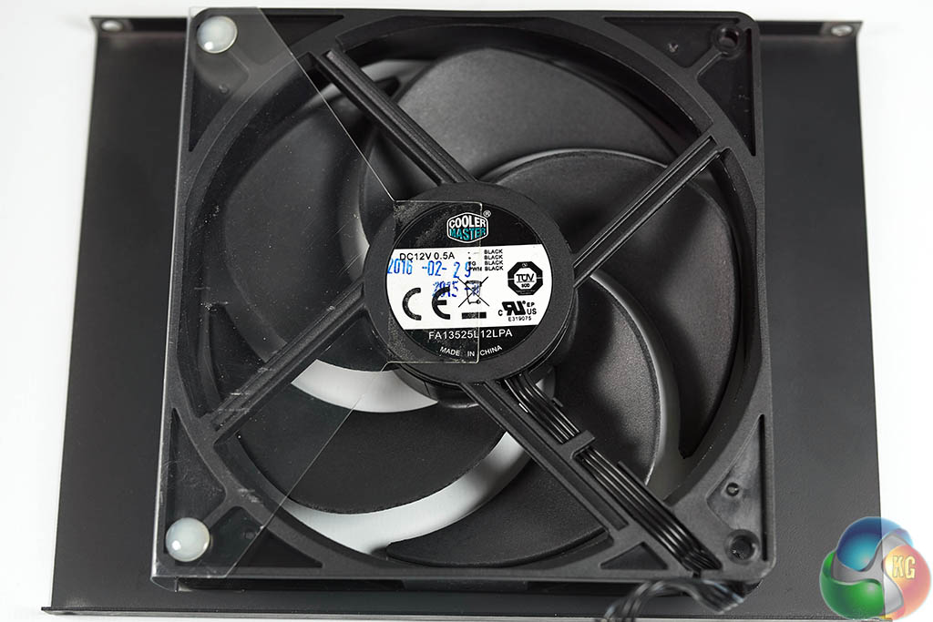
Cooler Master are using a 135mm FA13525L12LPA fan, this is a loop dynamic bearing fan with a rated life span of around 160,000 hours. The maximum speed is close to 3,000 rpm.
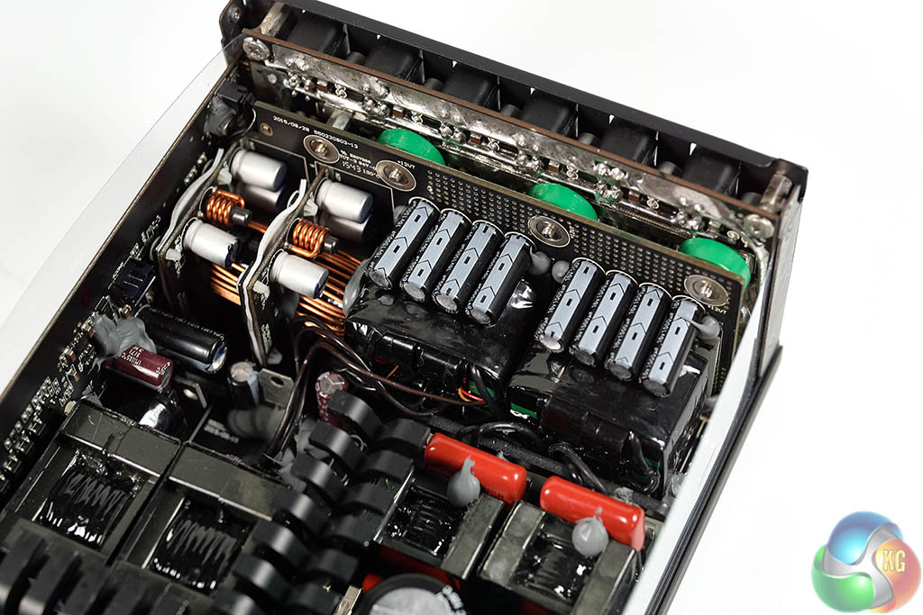
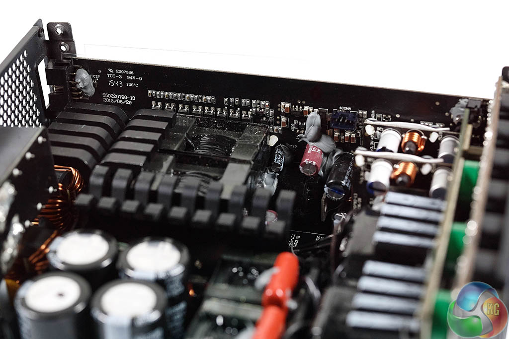
As we detailed earlier in the review, Cooler Master are using Enhance as the OEM partner for the design of this power supply. I have to say I was more impressed by the manufacturing quality of this unit than any other Enhance design I have reviewed in previous years. Considering the Titanium efficiency I was surprised Enhance had opted for such large heatsinks. Never a bad thing mind you.
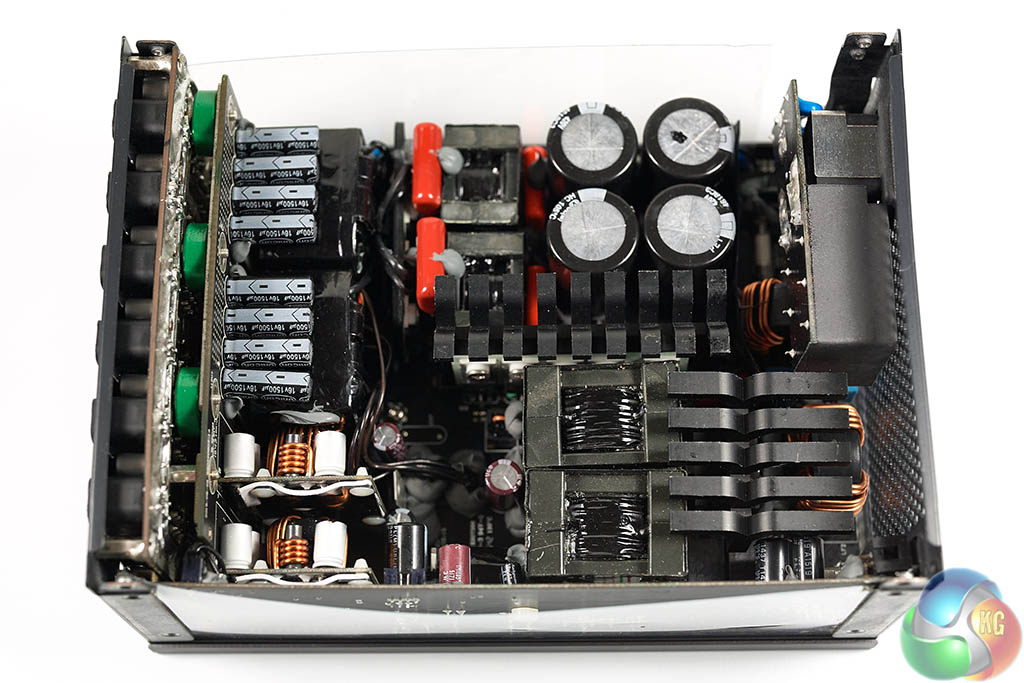
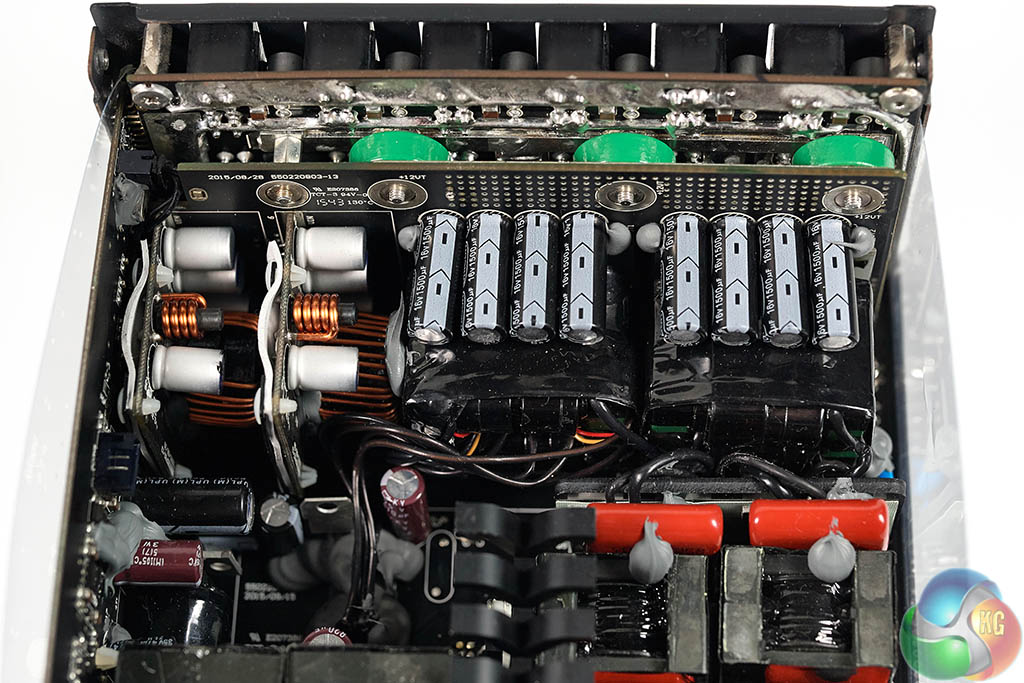
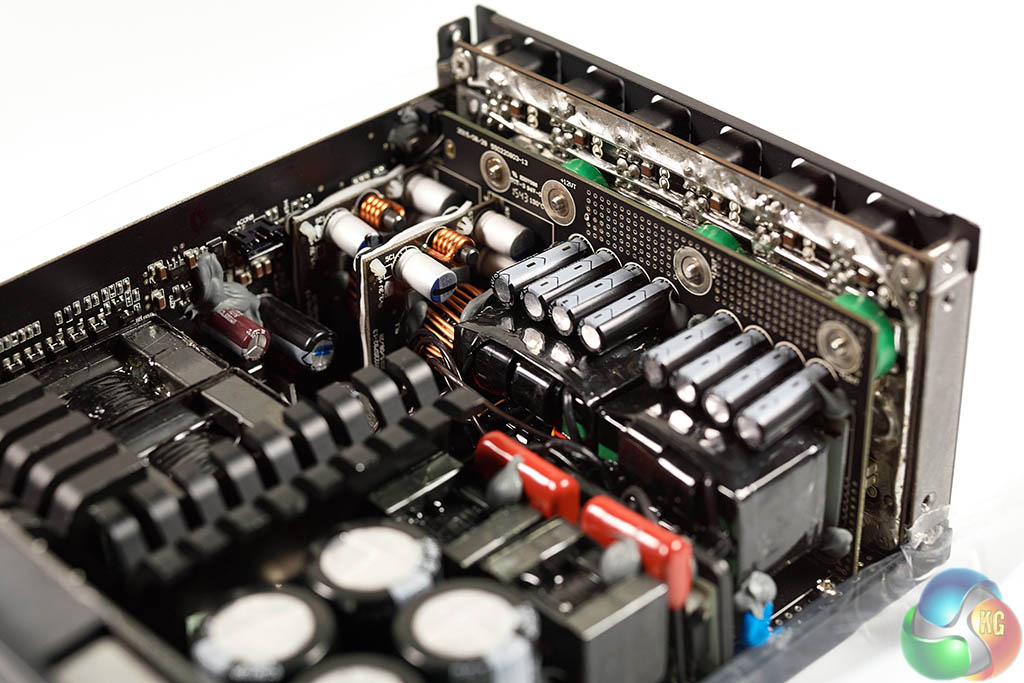
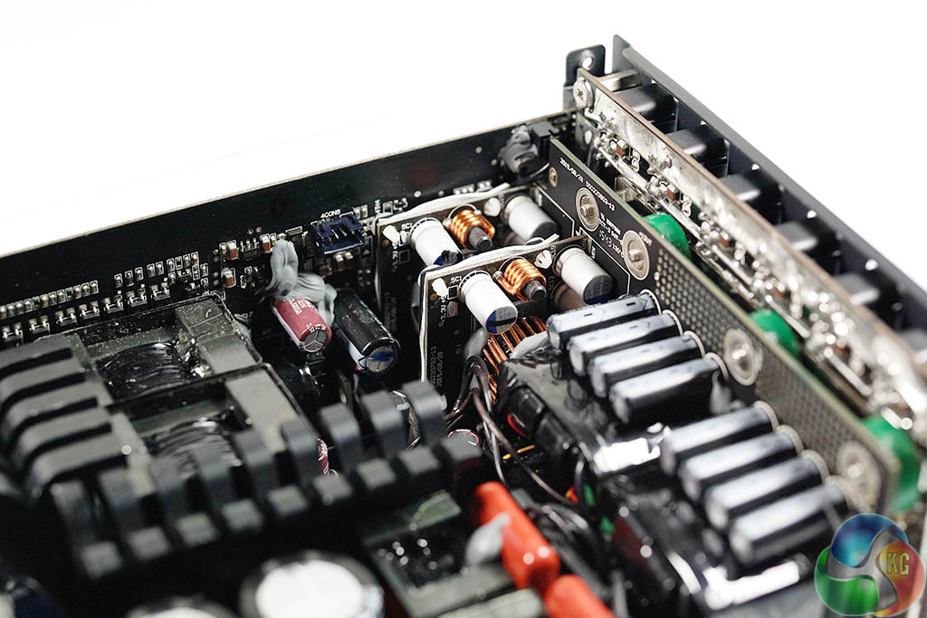
Enhance have cleverly placed a large PCB hosting the FET's behind the modular board. This regulates the +12V rail. The primary transformers are very close to the +12V FETS along with the modular board. This helps reduce energy losses as the current obviously moves across shorter distances with less resistance.
PCB soldering is very high indeed with no noticeable issues apparent.
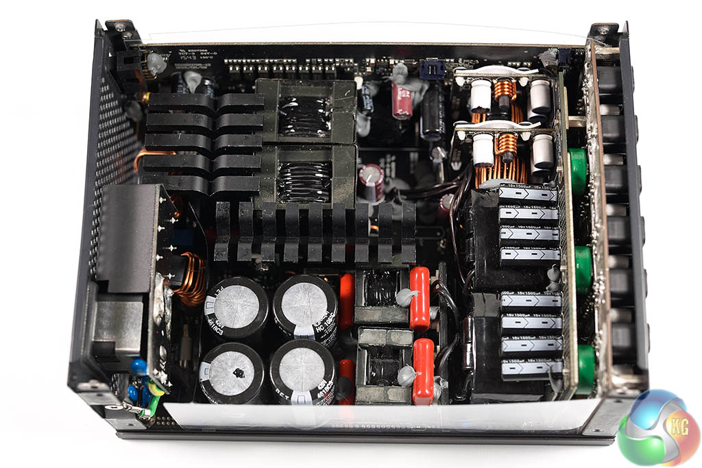
As the images above show, the design of this power supply is very condensed, there is very little room for airflow. We noticed that Cooler Master have positioned the bulk caps and the electrolytic capacitors on the secondary side to get some air flow, which was wise.
The first stage of the transient filtering starts at the AC receptacle and comprises a pair of Y caps and three X caps. This moves onto the main PCB with an extra X cap, two Y caps, an MOV and two CM chokes. Nichicon supply the polymer filtering caps.
Regular readers will remember our review some time ago of the Corsair AX1500i which was a pure digital platform design. This Cooler Master MasterWatt power supply utilises an MCU as a link to communicate and for monitoring duties. APFC and switching control are dealt with by analog controllers not digital circuitry. While we could debate the use of analog parts in this design, the effectiveness of the design will be rated against the results.
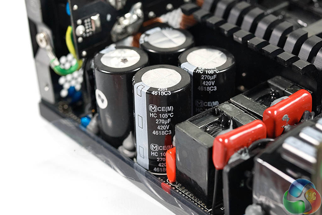
The primary side incorporates an APFC converter as well as full bridge topology – and two DC-DC converters generate the minor rails. FETS to regulate the +12V rail are installed on a little board set close by to the main transformers.
It is good to see the capacitors are Japanese, supplied by Rubycon and Nippon Chemi Con – rated at 105c. They are using four in the primary stage to help split the demand.
While im still not quite ready to leave my beloved Superflower PSU behind i’m curious why they went with Bluetooth 3.0. I know its a feature that very few people will use (bring on the world psu over clocking championships…. With ln2 is booooooom) i’d have thought having bluetooth 4.0 or with the advent of iot bluetooth 4.1 on the box would have made a better marketing gimmick?
Other than that another strong product in CM’s growing Maker lineup.
<<hp. ★★✫★★✫★★✫★★✫★★✫★★✫★★✫★★✫★★✫★★✫★★✫★★✫★★✫★★✫★★✫★★✫★★✫★★::::::!ir265m:….,……