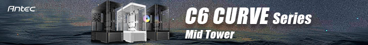

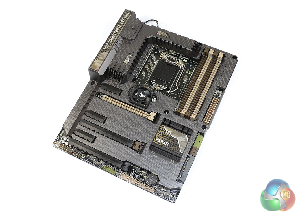
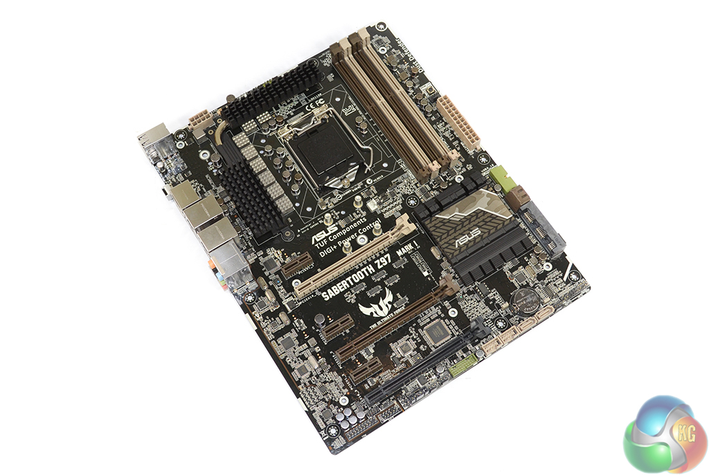
Colour-wise, the Asus Sabertooth Z97 Mark 1 retains the unique blend of camo-style shades that have given the series its distinct appearance. The concoction of shades form a truly ‘hate-it-or-love-it’ colour scheme. One thing is for certain – matching component colours with a TUF series motherboard is not the most straightforward of tasks; any colours other than jet-black are likely to clash.
As has become one of the distinct staple points of Asus TUF series motherboards, Thermal Armor continues to show its face with the Sabertooth Z97 Mark 1. Thermal Armour is a hotly debated topic; many users suggest that it can offer better cooling performance, while others deem it a waste of time.
There is a key point that acts as validation as to Asus' continuous implementation of the thermal cover on its TUF series motherboards; lower component temperatures help to increase part longevity, be it via blocking thermal radiation from external sources or preventing dust build-up to allow optimal convection cooling.
Taking performance points out of the equation, Thermal Armour manages to create a unique appearance. An additional benefit of Thermal Armour on the TUF series boards is that the potentially-hated colour scheme can be largely hidden in favour of a black cover.
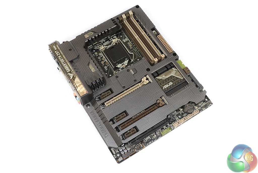
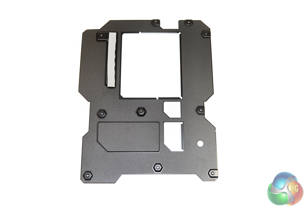
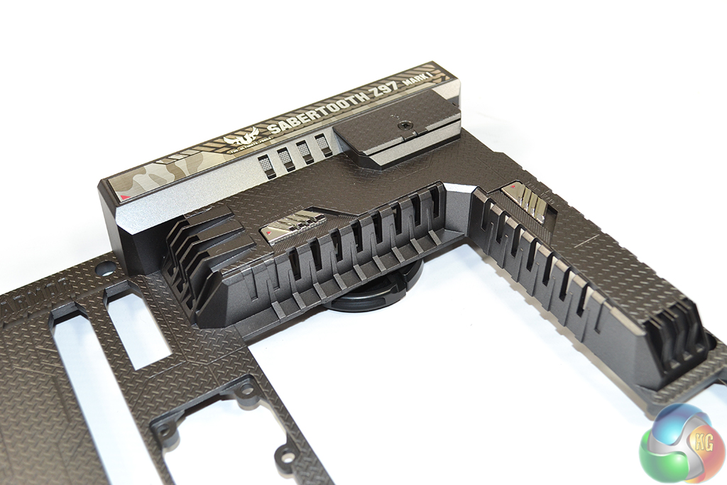
The TUF Fortifier rear plate helps to increase the motherboard’s flexural strength, allowing heavy CPU heatsinks to be mounted with fewer worries. Rear cooling of the MOSFETs is also conducted by the metal TUF Fortifier plate, with assistance from a thermal pad.
It's worth noting that the TUF Fortifier plate increases the Sabertooth Z97 Mark 1 motherboard's thickness by a few millimetres. This will not cause issues for users mounting the board inside a chassis, on stand-offs, but it may prevent cables from being routed behind the motherboard for aesthetic purposes.
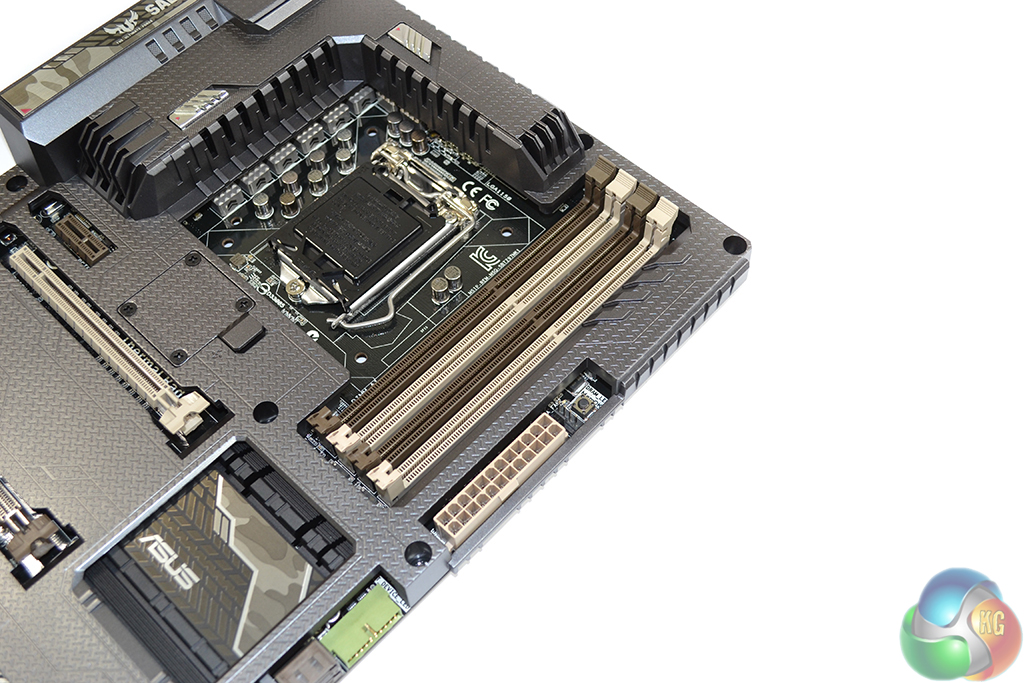
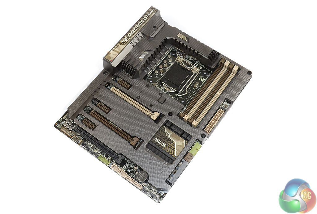
Four brown and beige DIMM slots provide support for up 32GB of DDR3 memory. Asus quotes maximum memory speed support for 1866MHz sticks, although further investigation shows the UEFI providing dividers up to 3400MHz. Each memory slot uses Asus' convenient single-latch mechanism.
Asus' handy MemOK button is present on the Sabertooth Z97 Mark 1, allowing users to boot the system when their memory speed is causing issues. One 4-pin fan header is found next to the MemOK button, in a convenient location.
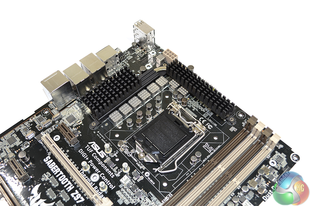
Called TUF Engine, the Sabertooth Z97 Mark 1 uses digital power controllers (Digi+ VRM) and military-certified electronic components. An eight phase power delivery system feeds the LGA 1150 CPU socket. Titanium solid-state 10K capacitors and 40A chokes are used.
Being a TUF motherboard, the electronic components used have been subjected to military-standard testing to validate their stability and reliability. For example, the capacitors are subjected to a barrage of tests, including; a thermal shock test, a moisture resistance test, a vibration test, a mechanical shock test, and more. The MOSFETs and chokes are also put through a number of tests to certify their stability.
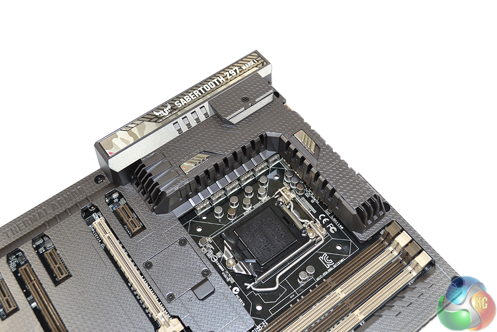
At 35-40mm in height, Thermal Armour's VRM covering has the potential to cause interference with large CPU coolers. We managed to mount a be quiet! Dark Rock Pro 3 and Noctua NH-D15 without interference.
Three desktop fan headers and an 8-pin power connector are located along the motherboard's upper edge. Two 4-pin fan headers operate from the CPU PWM channel, while an additional powered 3-pin header offers convenience for connecting an AIO cooler's pump unit, as we did with our Corsair H100i. A laptop-style header is allocated for Thermal Armour's cooling fan.
A positive side effect of the VRM heatsink's sizeable height is that cables connected to the upper-edge ports are masked and therefore do not create an untidy appearance.
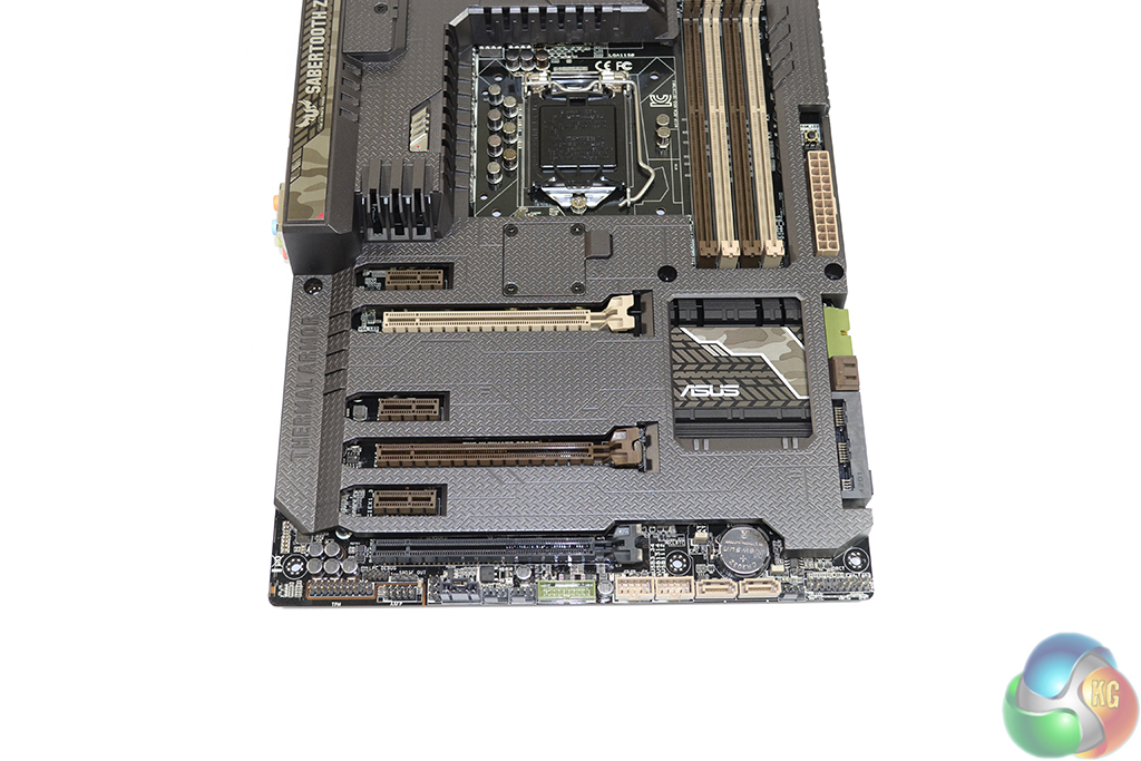
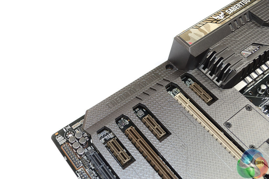
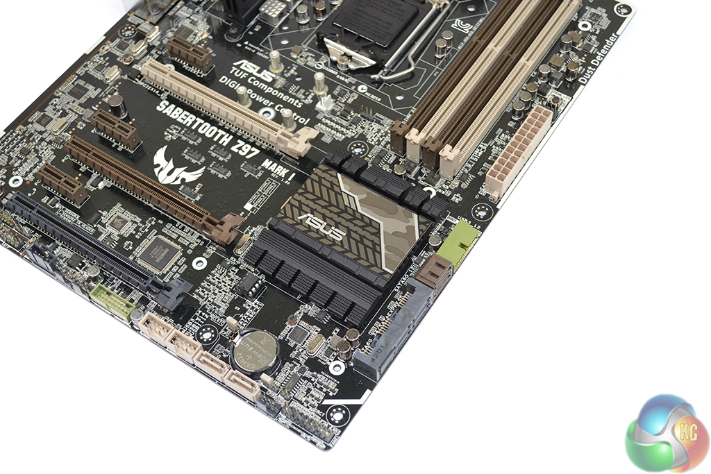
Asus does away with legacy PCI support and utilises an array of PCIe connectors for its Sabertooth Z97 Mark 1 motherboard. The beige and brown PCIe x16-length slots operate via an LGA 1150 CPU’s sixteen PCIe 3.0 lanes. 2-way CrossFire and SLI is supported via the upper two slots at x8/x8 bandwidth.
Up to four PCIe 2.0 lanes from the Z97 chipset feed the black PCIe x16-length slot which, technically, allows the Sabertooth to support 3-card CrossFire albeit with crippled bandwidth. A positive of using chipset-fed lanes is that a high-bandwidth PCIe interface SSD can be operated from the slot without stealing the CPU's lanes and disabling SLI (which requires full x8/x8 bandwidth).
The slot operates in x1 mode by default because the lowest PCIe x1 connection and two rear panel USB 3.0 ports must be disabled to enable x4 bandwidth.
Slot layout for the Sabertooth Z97 Mark 1 is what we consider to be perfect for a Z97 motherboard. Two triple-slot cards can be installed simultaneously, or a pair of dual-slot boards can be given a cooling space between them.
The Sabertooth Z97 Mark 1 relies upon an ASMedia ASM1184e one-lane to four-lane PCIe 2.0 switch to provide enough bandwidth for all of its onboard devices and expansion slots to function simultaneously.
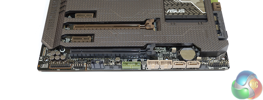
Along the motherboard’s bottom edge sit two add-on SATA 6Gbps connectors (bringing the board’s total to eight) provided by an ASMedia ASM1061 chipset. One of the Sabertooth's two internal USB 3.0 headers lies in the middle of the board's bottom-edge.
Front panel connections are the usual affair; the audio header sits to the left while the front panel chassis connections lie to the right. Three 4-pin fan headers are positioned on the board's bottom edge. Three thermal sensor headers also lie on the bottom edge, making hiding their cables a simple task.
The Trusted Platform Module (TPM) may be welcomed by productivity users who put emphasis upon the security of their system.
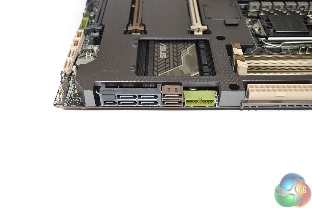
Storage interfaces on the Sabertooth Z97 Mark 1 include six chipset-fed SATA 6Gbps ports, with an additional two (on the board’s bottom edge, as shown above) being provided by an ASMedia controller.
A single 10Gbps SATA Express connection is formed by combining two SATA 6Gbps connectors and an additional data-carrying port. The SATA Express connector uses Asus' SRIS implementation that we discussed HERE.
The Sabertooth Z97 Mark 1 does not feature an M.2 connector which is disappointing for users waiting to see which path the storage industry takes before purchasing their new SSD. Lack of PCIe lanes is not the reason for M.2's omission; Gigabyte's Z97X-UD5H-BK re-directs lanes from its SATA Express port to the M.2 connector.
Asus mounts the other of the two front panel USB 3.0 headers adjacent to the SATA ports in a right-angled orientation. This is a smart move by Asus that very few boards have done in the past. Hiding the fat front panel USB 3.0 connector is a much easier task when the header is angled by ninety degrees.
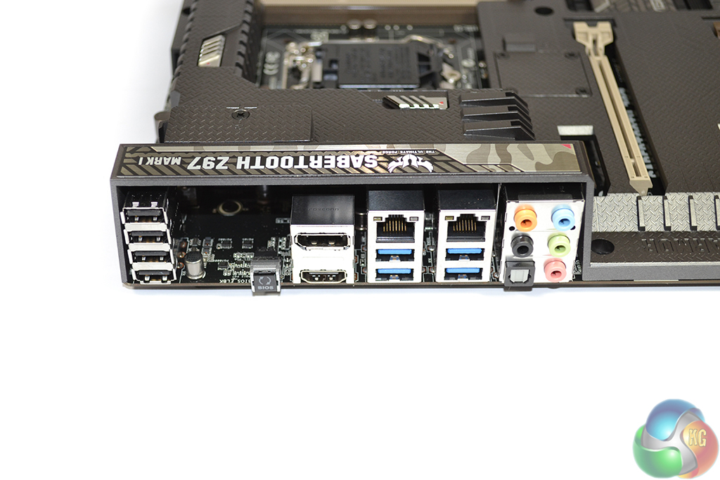
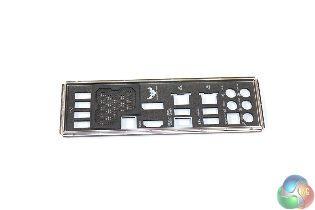
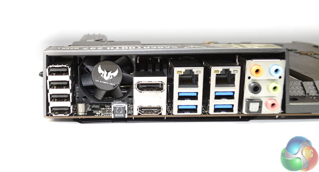
Two LAN ports, one provided by an Intel I218-V controller and the other fed by Realtek’s 8111GR chipset, allow users to choose their preference or use both at once. Two of the USB 3.0 connections are provided by a one-lane ASMedia ASM1042AE host controller, while the remaining pair link to the Z97 chipset.
Rear audio connections are powered by a Realtek ALC1150-based solution. Asus’ convenient BIOS flashback button is situated next to ASM1442K-assisted DisplayPort and HDMI connectors. A segment of the rear IO is left empty to provide mounting space for the 40 mm fan to cool the VRM area.
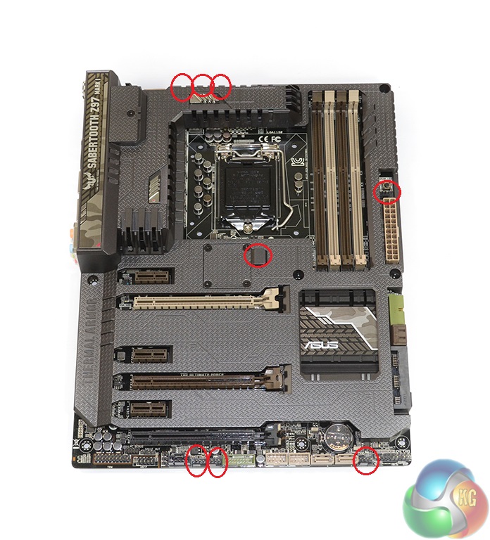
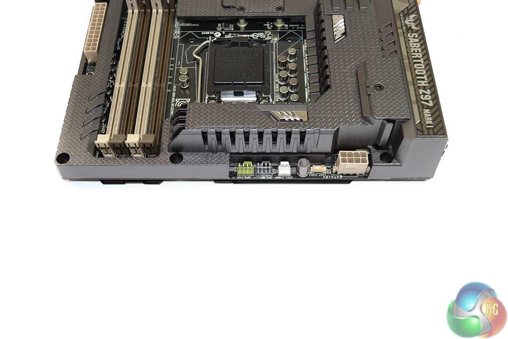
Asus equips the Sabertooth Z97 Mark 1 motherboard with a total of eight fan headers, six of which are 4-pin. The 3-pin header located mid-board is designed for use with the 35 mm fan that can be mounted in Thermal Armor.
Distribution of the fan headers is excellent; an additional 3-pin connector in the CPU area can be used to power an AIO cooler's pump or a rear chassis fan. The 4-pin header located above the 24-pin connector is ideal for roof or front intake fans.
Key to the Sabertooth Z97 Mark 1's design are its thermal sensors. Asus deploys additional (compared to ‘standard' consumer alternatives) thermal sensors on its TUF series motherboard to permit for a greater level of monitoring. The Sabertooth Z97 Mark 1 utilises a total of 12 temperature sensors, 3 of which are provided by user-operable thermistor cables. We outline sensor positioning in the software portion of this review.
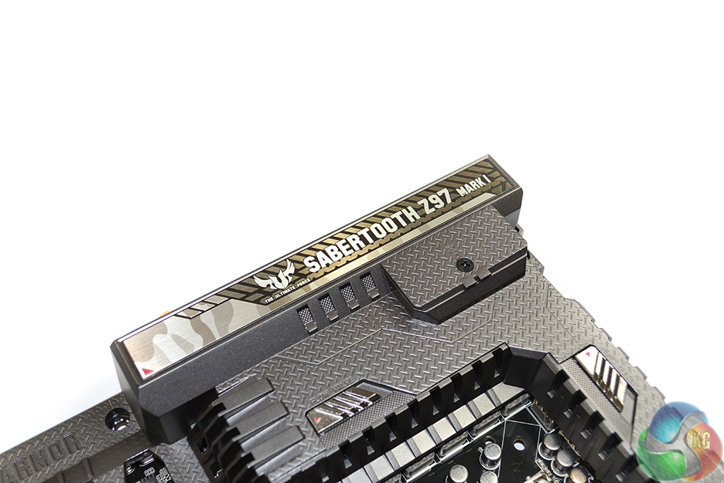
Names are embossed into the Thermal Armor and printed onto the IO shield cover for additional bragging rights.
Thermal Armor Features
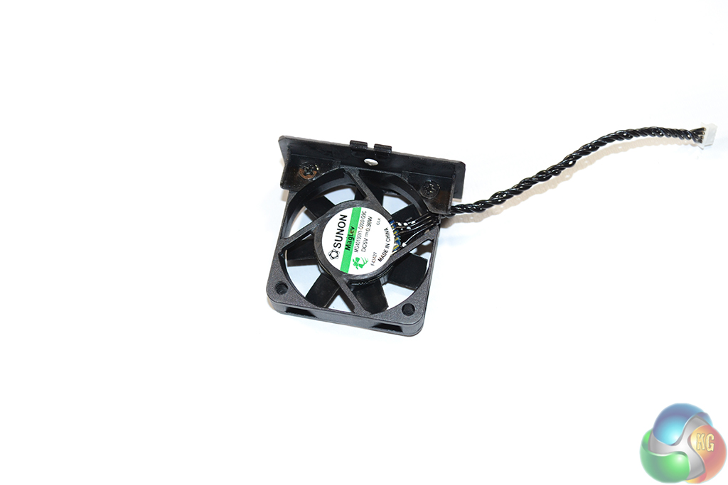
Preparing the 40 mm VRM fan for installation is as easy as removing its cover and connecting it via two screws. Asus' installation guide outlines the process well, including the relevant installation direction. A dust filter can be mounted to the IO shield to prevent additional dirt entering the VRM heatsink.
I would recommend installing the 40 mm fan before mounting the motherboard into a chassis – the procedure is fiddly and will become frustrating in a confined space.
The 40 mm fan fits tightly below the VRM section of Thermal Armor. Its direction of flow is intended to bring cool air from outside of the chassis and blow it over the power delivery components, transferring their heat away via convection.
As we were quick to identify, dust build-up will rapidly become an issue with a 40 mm bringing air in at a typical speed of 3800rpm. Asus combats the issue of heatsink fouling with a feature call Dust De-Fan. Akin to graphics cards that use a high-speed burst of air to expel dust from their coolers, Dust De-Fan has the potential to minimise the negative effects of dirt build-up.
Dust De-Fan works by reversing the fan's direction of rotation for a user-definable time period (0, 15, 30, or 45 seconds), on start-up. This 6000rpm burst helps to lift dust from the MOSFET heatsink and force it through a vent. After the set period of time, the 40 mm blower reverses its direction, acting as an intake fan to cool the VRM.
A user can set distinct intervals for Dust De-Fan to kick in during Windows usage. The time intervals are: 1, 2, and 4 hours. Alternatively, users can prevent Dust De-Fan from running during system usage.
I was initially skeptical about the effectiveness and logic of the Dust De-Fan implementation, seeing it as potential marketing piece rather than a useful feature. After speaking with engineers from Asus' TUF department and asking them numerous questions for an extended period of time, I can see that Dust De-Fan is in fact a feature that the Asus designers deemed relevant to component longevity, rather than good for marketing.
A cover intended to reduce thermal radiation and convective heat transfer works both ways; Thermal Armor not only reduces the quantity of heat interacting with the board from external components, it also prevents motherboard-produced heat from exiting sources such as the MOSFETs and chokes.
Systems with a down-facing CPU cooler will provide the MOSFETs with incidental airflow, whereas an AIO liquid cooler mounted away from the motherboard may justify the use of a fan for providing airflow to the VRM.
As an additional combatant to the issue of cooling the motherboard’s PCB and electronic components situated beneath Thermal Armor, Asus adds flow vents and a top-down fan mount into the plastic cover’s design. While the 40 mm fan that we have already outlined takes care of VRM cooling, an additional 35 mm fan mounted in the ‘northbridge' location helps to force air beneath Thermal Armour, cooling the motherboard PCB.
Dust defenders are easy to install into expansion slots. We noticed that Asus uses defenders for the memory slots that are 30 mm-tall. We don't understand why Asus would use such large defenders when there is the clear potential for CPU cooler interference. Sub-20 mm pieces would have done an equally good job.
With 35- and 40-mm fans mounted to the board, spinning at over 3700rpm each under an idle state in Windows, there is no denying that Thermal Armour becomes a loud solution. At load speeds of over 5100rpm, the noise is borderline irritating. Using the standard fan speed level, the two small fans were clearly perceivable over the rest of our test system's components at idle.
Thermal Armor Removed
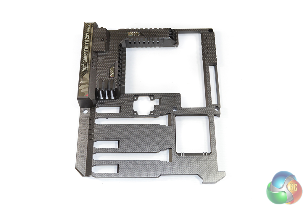
Constructed of a sturdy form of plastic, the Thermal Armour cover can be removed for cleaning purposes or for aesthetic reasons. Removal takes around five minutes and is completed by unfastening 15 screws.
A thermal pad added onto the TUF Fortifier plate helps to remove heat from the MOSFET, thanks to the metallic material's strong conduction performance.
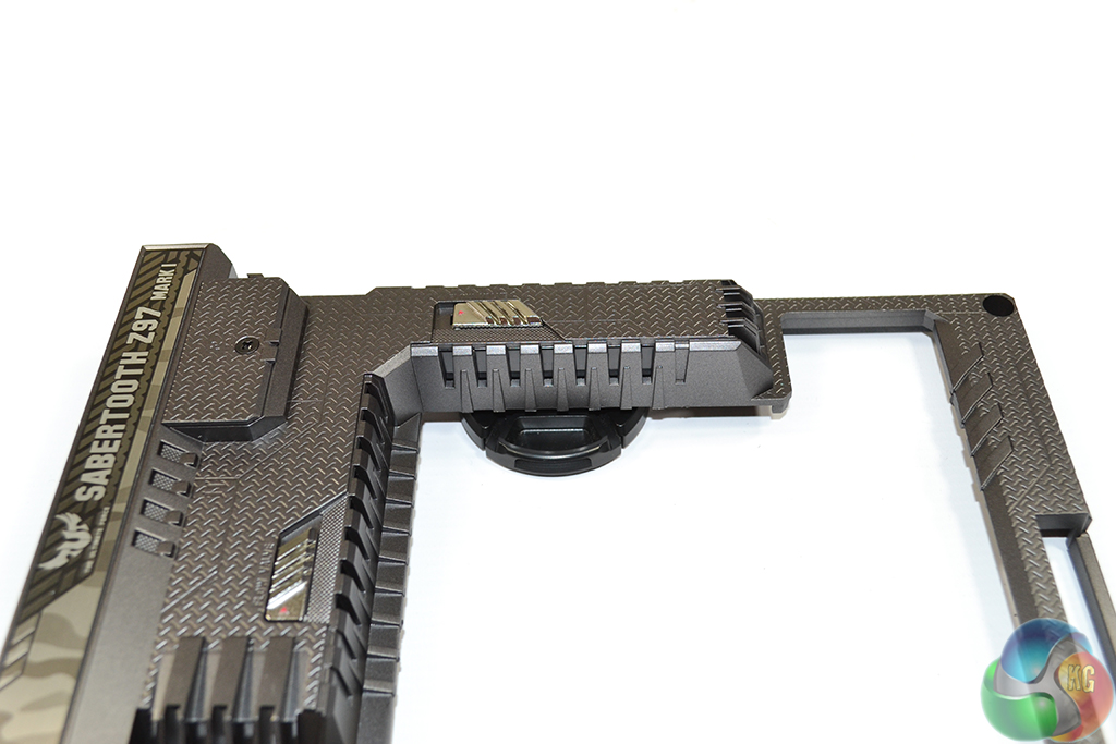
Users are free to open or close the two flow vents situated atop both MOSFET heatsinks, dependent upon their CPU cooling configuration. The above photos show the vents open and closed, using our Nikon lens cap for a perception of clearance.
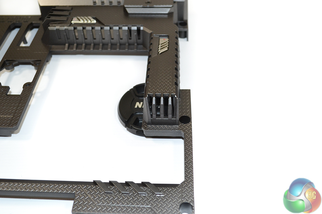
There is an open vent located directly in the airflow path of the 40 mm VRM cooling fan. The open vent helps to create an induced pressure differential, helping the air blown over the MOSFETs and chokes escape from beneath the plastic insulation that is Thermal Armor.
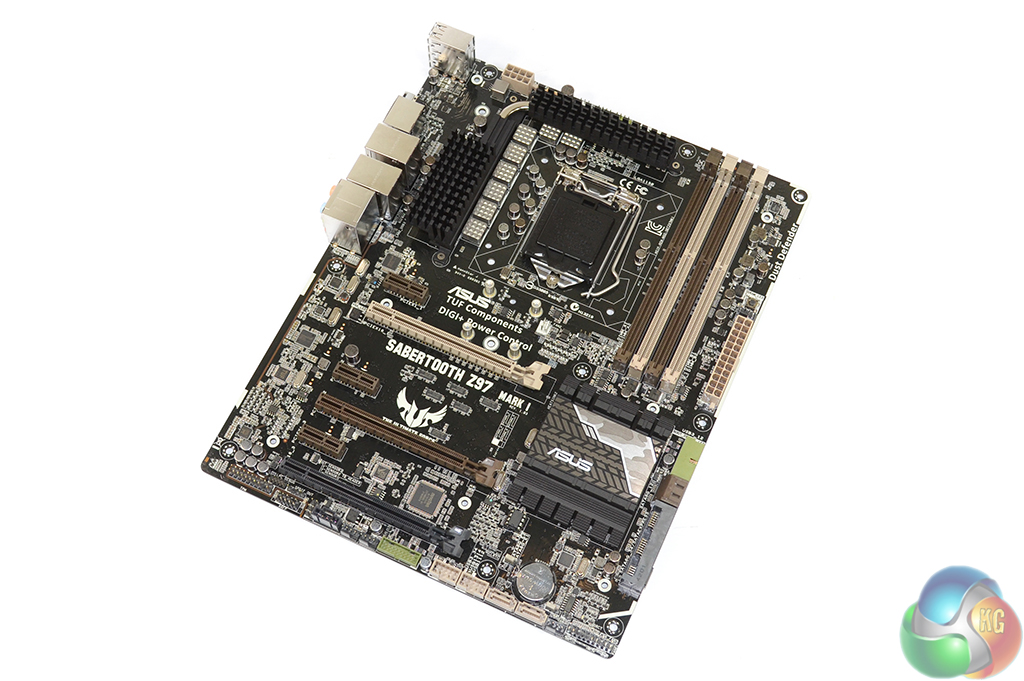
Despite covering the motherboard with Thermal Armor, Asus still makes a quality touch by building the Sabertooth Z97 Mark 1 around a fully black PCB. Mark 2 of the Sabertooth Z97 ships without Thermal Armor (presumably with a lower price tag) and will look similar to the above pictures.
A Nuvoton NCT6791D chipset, in tandem with a proprietary TUF ICe controller, takes care of monitoring and fan control duties.
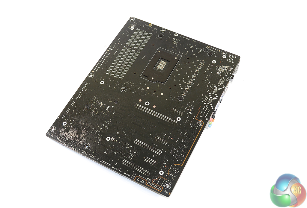
A photograph of the board's rear side shows the discrete pathway that signals deriving from the Realtek ALC1150-based solution travel through. Signals are sent along the discrete pathway, with separated left and right tracks, to avoid interference between each audio channel as well as the rest of the board.
Asus uses heavy duty heatsinks to draw thermal energy away from the MOSFETs and Z97 chipset. My ‘touch test' implies that the heatsinks are constructed of a form of anodised metal.
Luke, brilliant review and so much detail, took me 30 minutes reading it this morning. I love Kitguru’s motherboard (and GPU) reviews! This is top of my shortlist when the new K series come out.
What is going on? Why is everyone copying the ASUS red and black board designs? Nice to see ASUS (who started it all) using different colours.
Sabretooth are my favourite boards. always have been. ill be getting this one soon
I think thermal armor is a gimmick in regards to temperatures, but I like the dust protection and protection over the capacitors. I can be rough on the boards when installing them. Nice looking board – interested in SATA express too, as I have a lot of large files I move around often
based on your reviews I included the sabertooth mark 1 in my new build, also your reviews let me decide my gpu, gigabyte GTX770OC, psu seasonic X-Series 650W KM3 gold and now my ram, G.Skill ARES 16 g kit. Cheers for taking the stress out of my build
May I turn-off the small fans? Or just remove them? It is
going to have some significant impact in the performance or will the MB get
overheated?
Thanks!