

The Hydro PTM 650W is a mid-capacity power supply that targets a very competitive market. It is offered at a good price and the provided warranty is ten years but is the performance good enough to go after the highly popular Seasonic Focus Plus Platinum and the top-notch EVGA 650 P2 models?
FSP's Hydro PTM line consists of three models with capacities ranging from 550W to 750W, mostly addressing mid-level systems with not so energy hungry components. Despite the ‘Hydro' naming (ὕδωρ), which means water in ancient Greek, all those units use air cooling. Only the Hydro PTM+ models utilize a hybrid cooling solution where both air and water cooling can be combined.

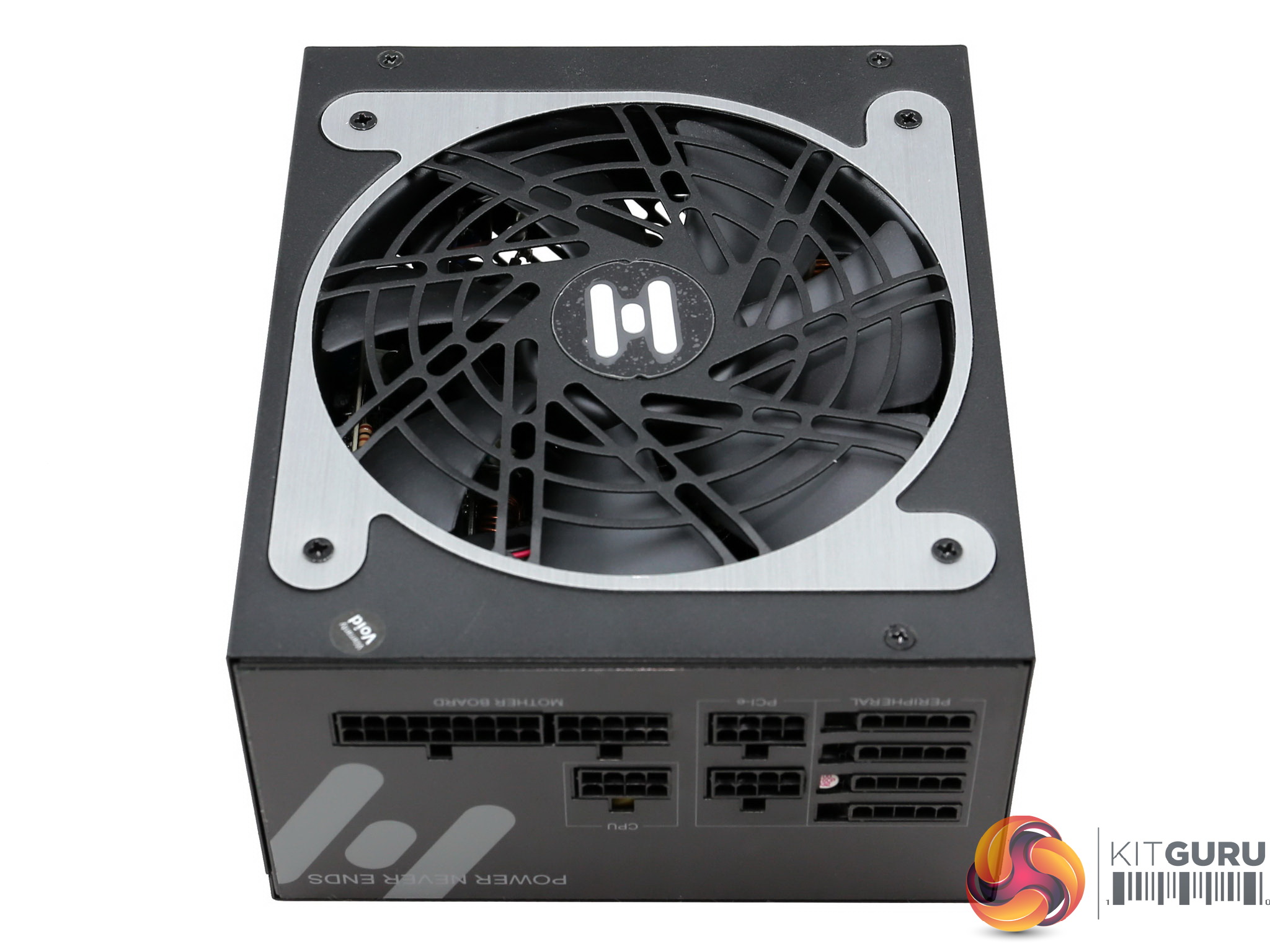
The FSP HPT650M is an attractive looking power supply and it is equipped with plenty of cables and connectors, with all of them being modular. FSP are obviously confident with the internal design and the choice of components given the long warranty they are offering, so it will be interesting to take it apart later in the review.
For those of you who are not familiar with the PSU market, we should note that FSP is one of the largest power supply manufacturers and besides desktop PSUs it also makes server units, power adapters and special purpose power supplies (e.g. telecommunications, medical PSUs etc).
This means that the platform of the HPT650M is designed and manufactured by FSP and not by a third party as usually is the case with many other units. Nowadays the list of known power supply manufacturers is not that long, with the majority of brands selecting a platform and asking for some modifications before they re-label it.
Some major brands, like Corsair for example can set specific requirements for a project and actually take part in the production phase, since they have engineers on their payrolls. Apparently it is too expensive to have a PSU manufacturing line so it is better to subcontract one for your needs, if you want to offer something different.
Read our How We Test Power Supplies HERE
Specifications
| Manufacturer (OEM) | FSP |
| Max. DC Output | 650W |
| Efficiency | 80 PLUS Platinum, ETA-A (88-91%) |
| Noise | LAMBDA-A (20-25 dB[A]) |
| Modular | ✓ (Fully) |
| Intel C6/C7 Power State Support | ✓ |
| Operating Temperature (Continuous Full Load) | 0 – 50°C |
| Over Voltage Protection | ✓ |
| Under Voltage Protection | ✓ |
| Over Power Protection | ✓ |
| Over Current (+12V) Protection | ✓ |
| Over Temperature Protection | ✓ |
| Short Circuit Protection | ✓ |
| Surge Protection | ✓ |
| Inrush Current Protection | ✓ |
| Fan Failure Protection | ✗ |
| No Load Operation | ✓ |
| Cooling | 135mm Fluid Dynamic Bearing Fan (MGA13512HF-A25) |
| Semi-Passive Operation | ✗ |
| Dimensions (W x H x D) | 152 x 88 x 172mm |
| Weight | 1.7 kg (3.75 lb) |
| Form Factor | ATX12V v2.4, EPS 2.92 |
| Warranty | 10 Years |
The HPT650M is 80 PLUS Platinum while in the Cybenetics scale it meets the ETA-A and LAMBDA-A requirements in efficiency and noise output, respectively. Given the noise certification we can easily state that this is a silent unit, although it doesn't feature a semi-passive operation, which is not absolutely necessary though for low noise operation.
The cooling fan is of very high quality and it uses a fluid dynamic bearing, so it will last for quite long, under normal operating temperatures at least. Lastly, all necessary protection features are present while the unit's dimensions are quite large, given that the similar capacity SSR-650PX measures 32mm less in depth.
Power Specifications
| Rail | 3.3V | 5V | 12V | 5VSB | -12V | |
| Max. Power | Amps | 20 | 20 | 54.17 | 2.5 | 0.3 |
| Watts | 120 | 650 | 12.5 | 3.6 | ||
| Total Max. Power (W) | 650 | |||||
The +12V rail can deliver the unit's full power alone, something typical in PSUs with DC-DC converters for the generation of the minor rails. The 5VSB rail has enough capacity for a mid-level system, while the minor rails are set at 120W max combined power.
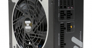
Cables & Connectors
| Modular Cables | ||||
| Description | Cable Count | Connector Count (Total) | Gauge | In Cable Capacitors |
|---|---|---|---|---|
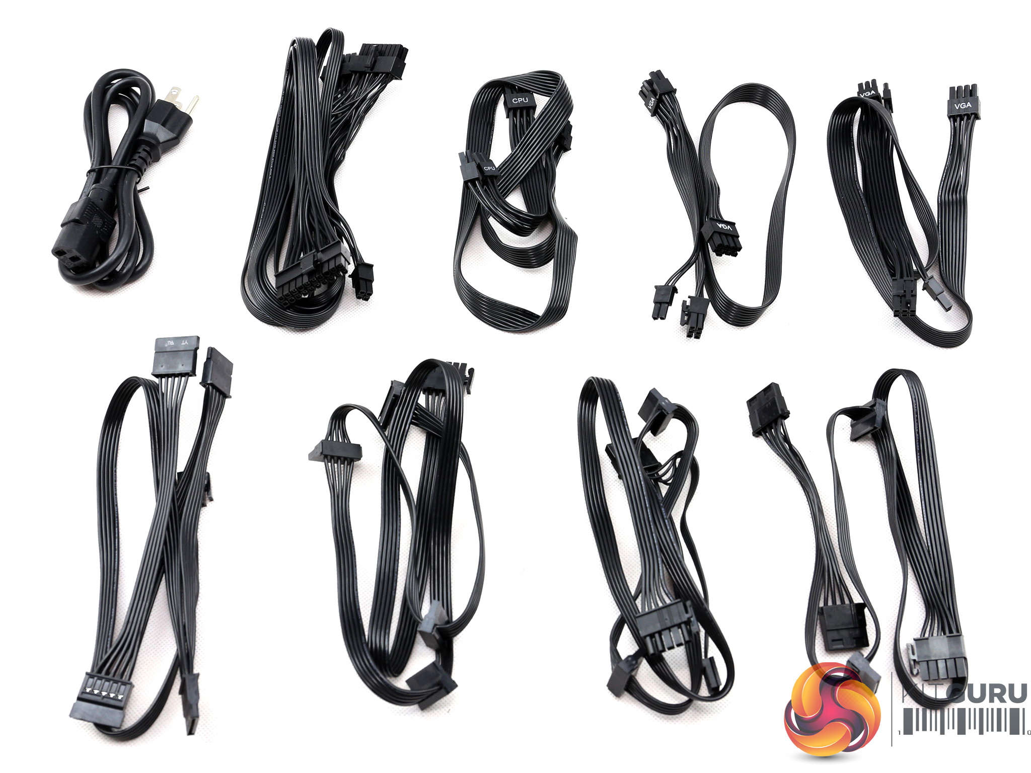
| ATX connector 20+4 pin (600mm) | 1 | 1 | 18-22AWG | No |
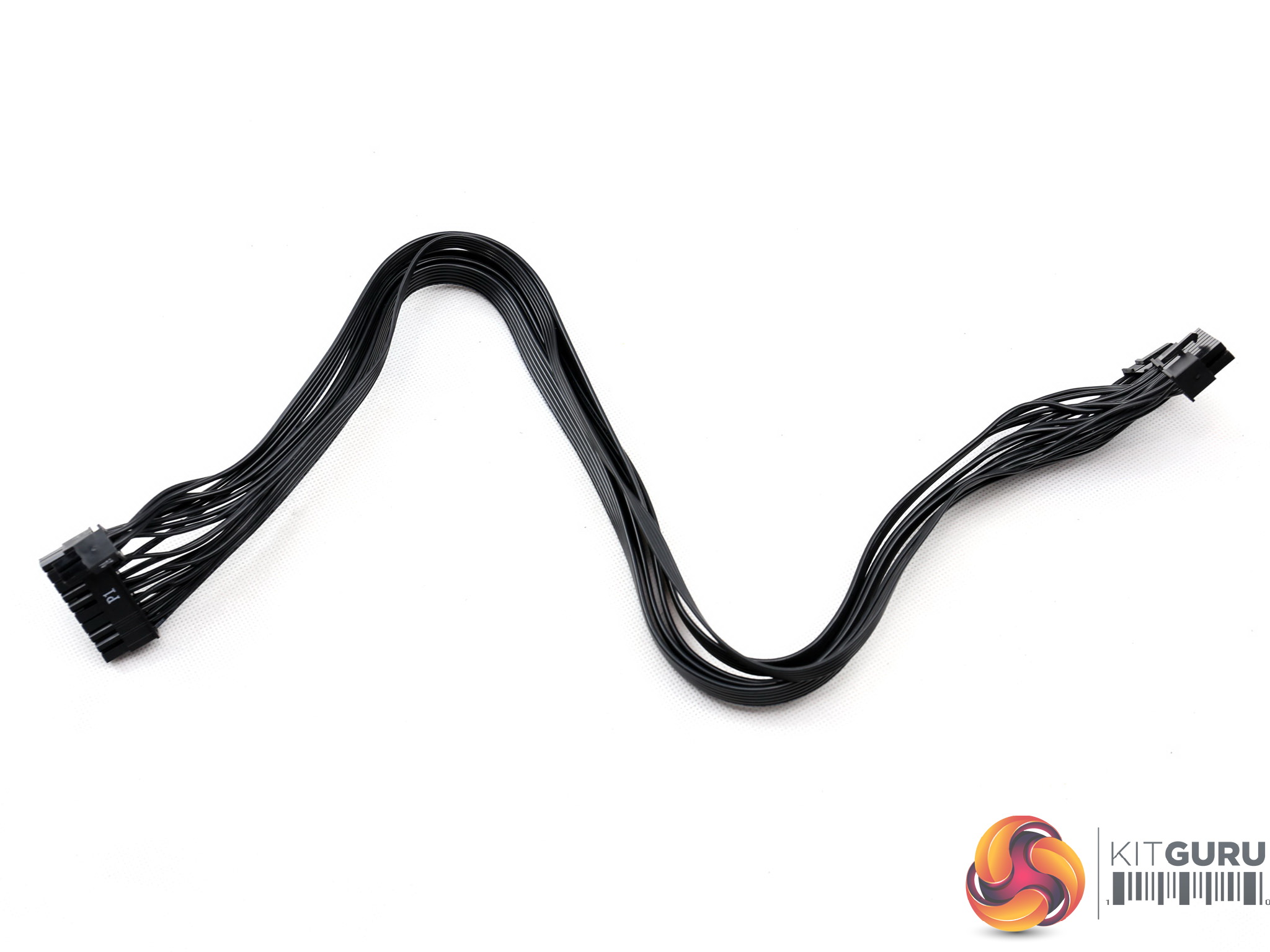
| 8 pin EPS12V (700mm) / 4+4 EPS12V (+150mm) | 1 | 1 / 1 | 18AWG | No |
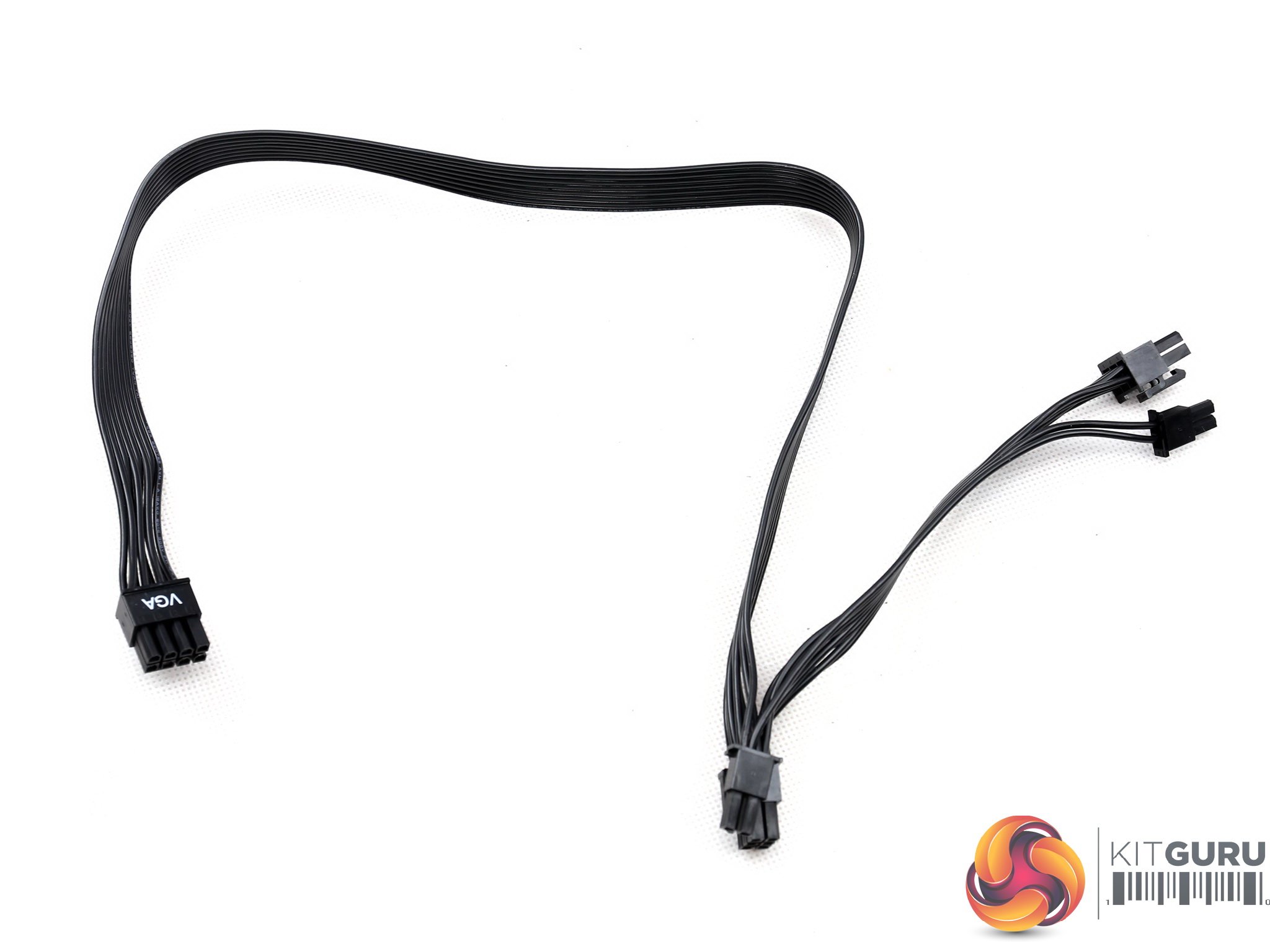
| 6+2 pin PCIe (650mm+150mm) | 1 | 2 | 18AWG | No |
| 6+2 pin PCIe (500mm+150mm) | 1 | 2 | 18AWG | No |
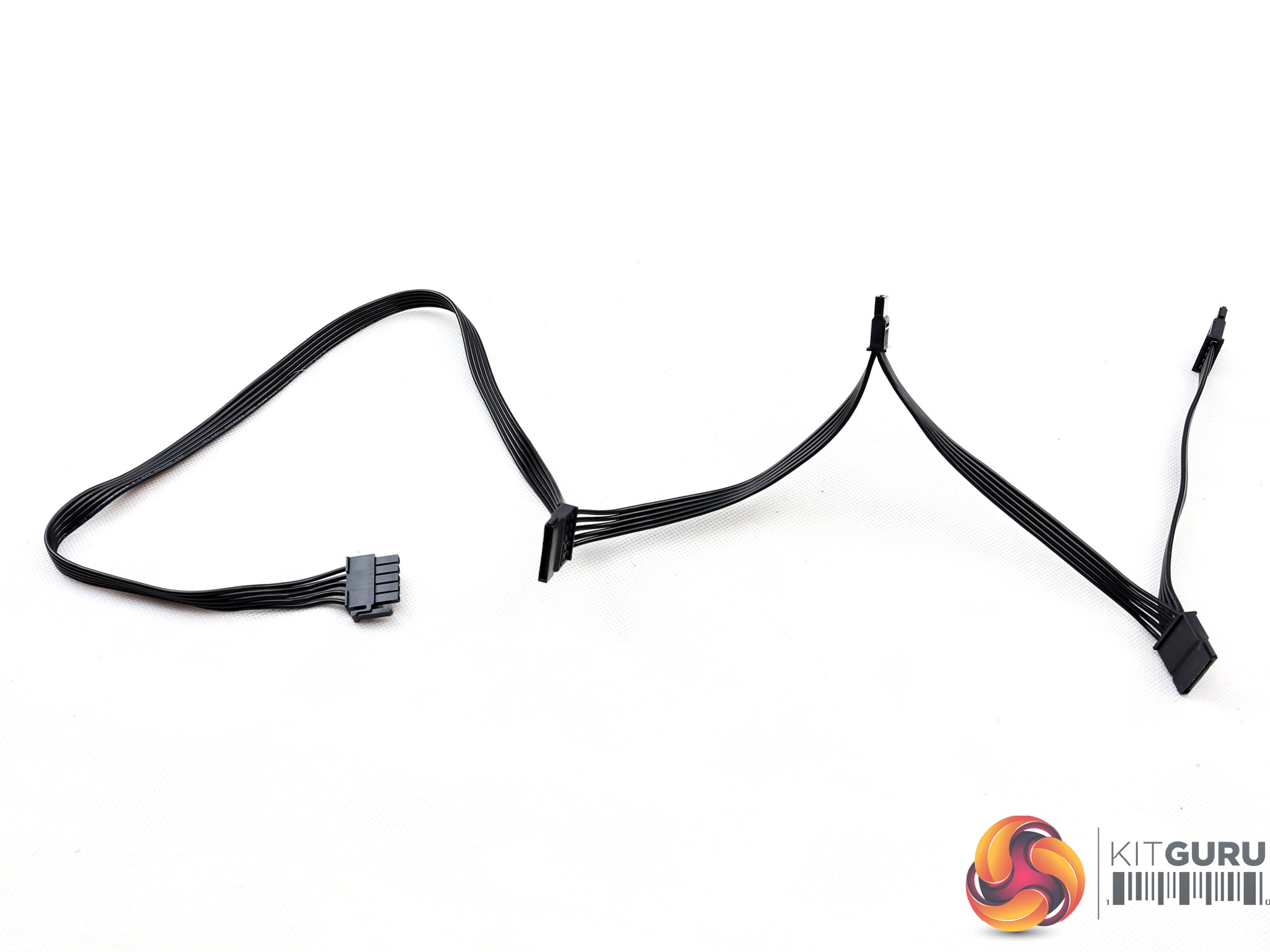
| SATA (500mm+150mm+150mm+150mm) | 2 | 8 | 18AWG | No |
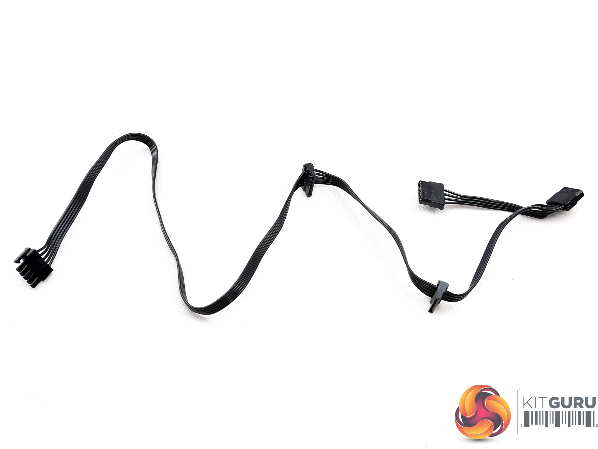
| SATA (500mm+150mm) / 4-pin Molex (150mm+100mm) | 1 | 2 / 2 | 18AWG | No |
| SATA (500mm+150mm) / 4-pin Molex (150mm) / FDD (+150mm) | 1 | 2 / 1 / 1 | 18-22AWG | No |
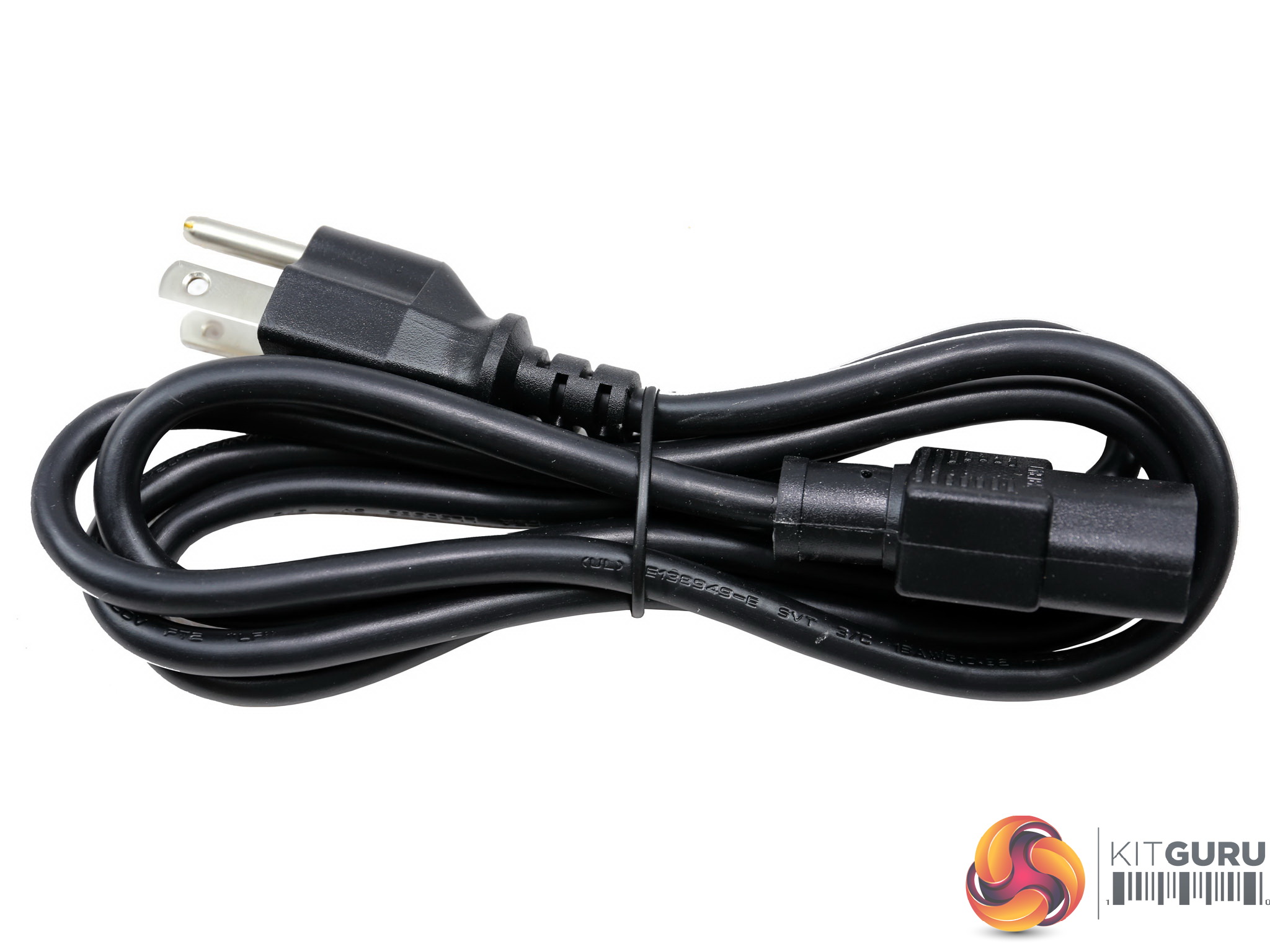
| AC Power Cord (1400mm) – C13 coupler | 1 | 1 | 16AWG | – |
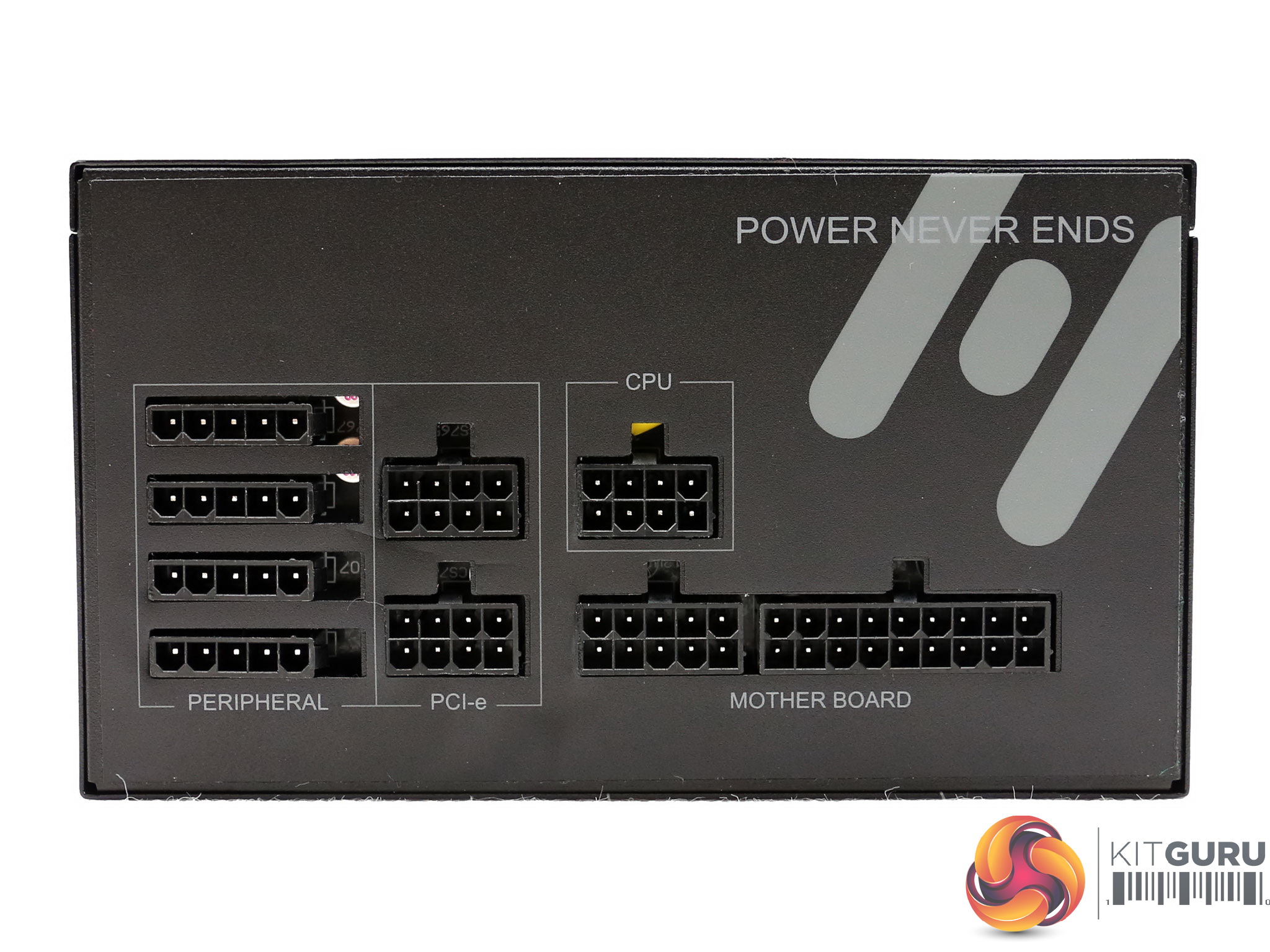
It is good to see a couple of EPS connectors, but FSP should install them in separate cables. Given that each EPS connector can deliver up to 336W on paper and considering that this PSU can work with a server mainboard equipped with a couple of high core processors, then you will most likely have to deal with melted cables, with the connectors following next.
FSP should set a power limit for the couple of EPS connectors residing on the same cable.
As long as you use a single CPU (even if it is an AMD Threadripper) and you are not planning on seriously overclocking it, we don't believe that you will run into any problems.
All cables are long enough and the distance between all peripheral connectors (apart from a single 4-pin Molex) is ideal at 15 cm. What strikes us as odd is the addition of a fixed FDD connector in one of the modular cables. FSP should add instead a 4-pin Molex and provide an inexpensive 4-pin Molex to FDD adapter. This would also raise the number of 4-pin Molex connectors to four.
Please note that if you can't see the images in our galleries in this review, then you will likely need to disable your ad blocking software on our site as they are known to generate false positives with our gallery code.
Packaging
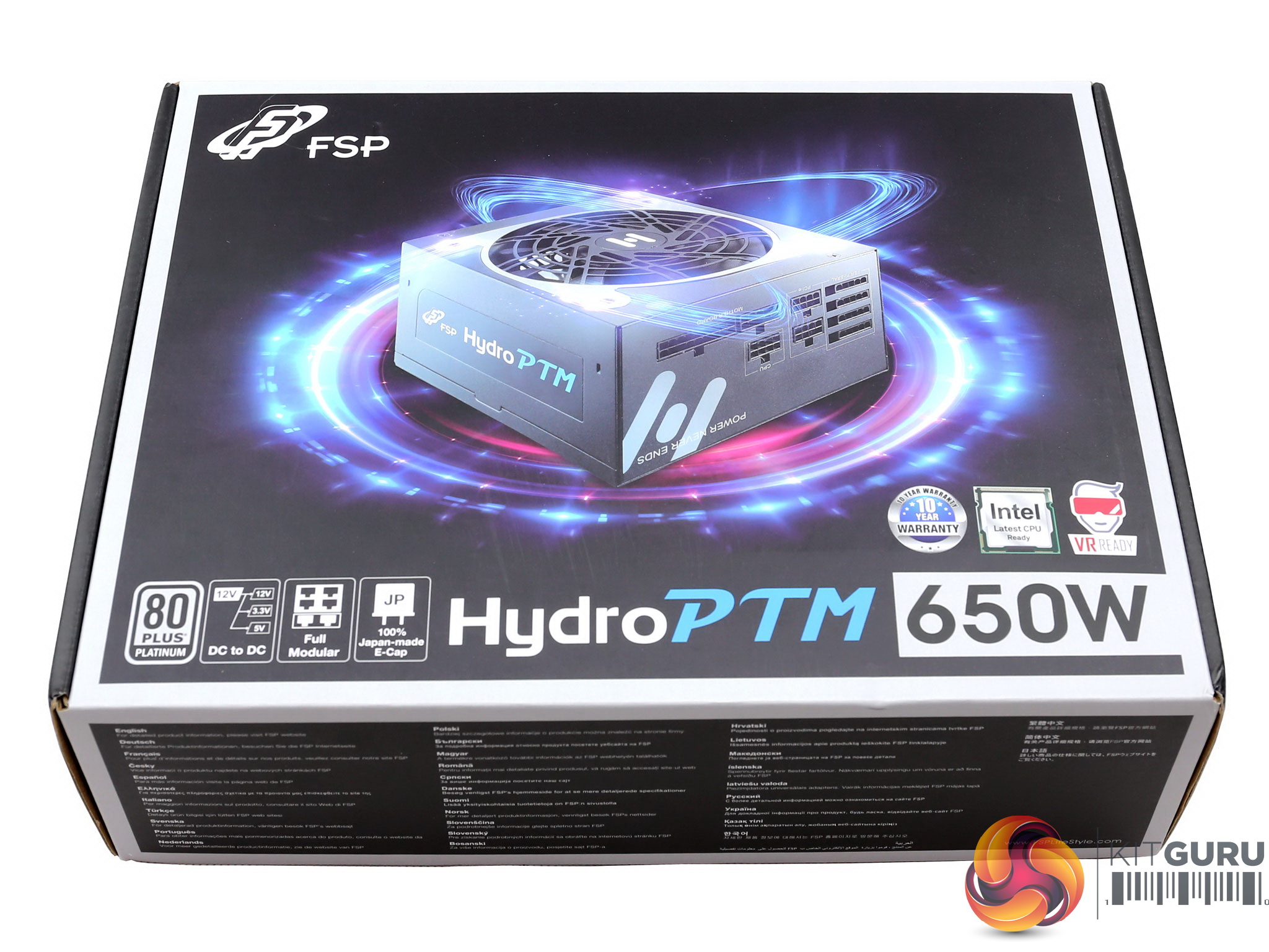
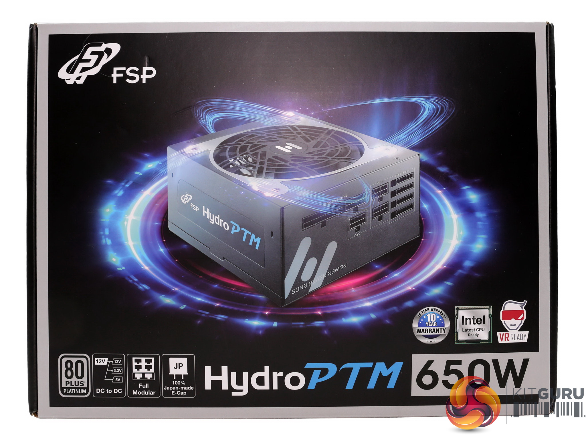
The box features some fancy graphics design with a power supply glowing at the front.
Right below the power supply photo we find a number of icons including the 80 PLUS Platinum badge, the series description along with the unit's wattage and three more icons describing the ten-year warranty, the compatibility with the newest Intel CPU sleep states and the support for systems strong enough to allow for VR gaming.
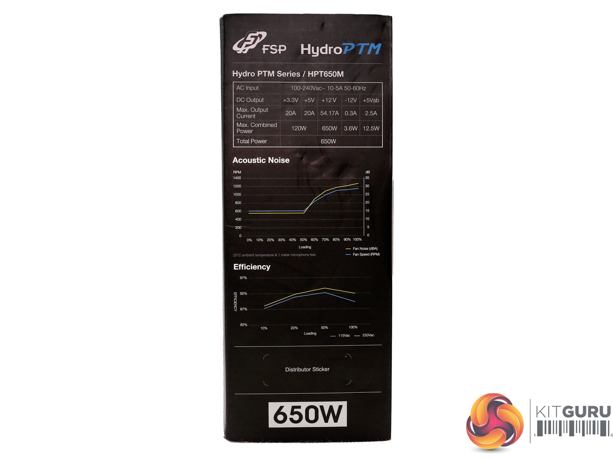
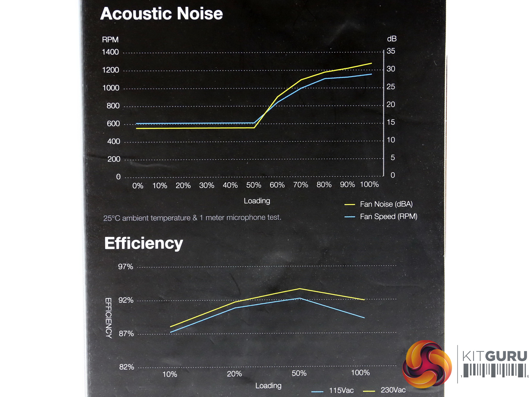
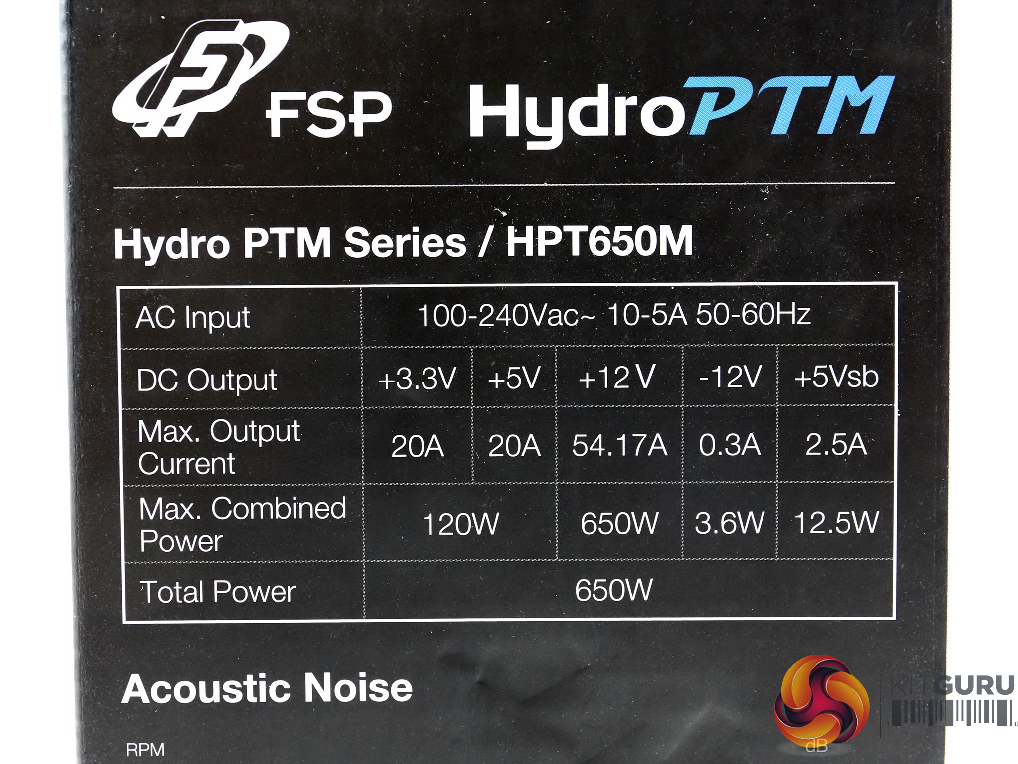
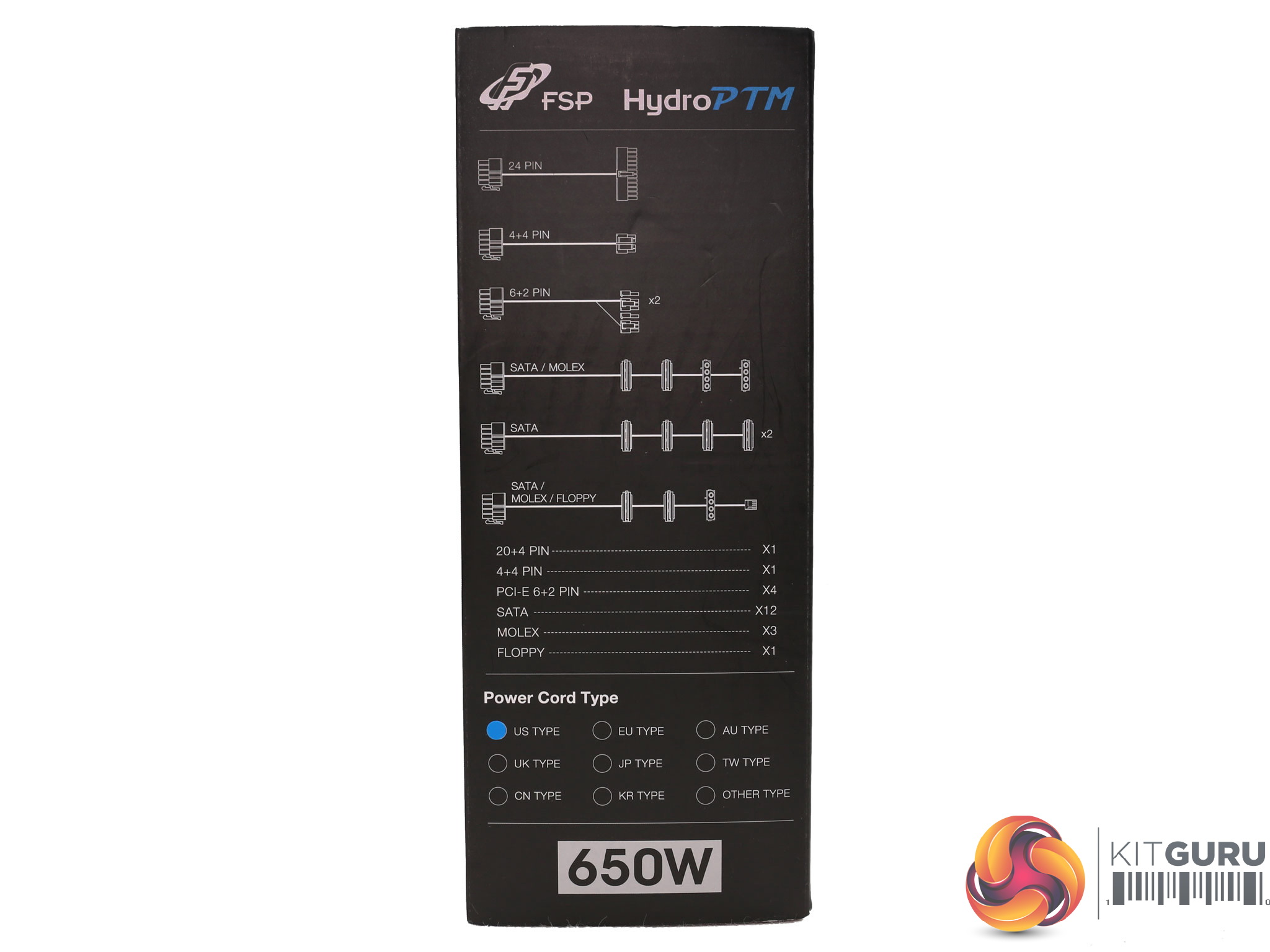
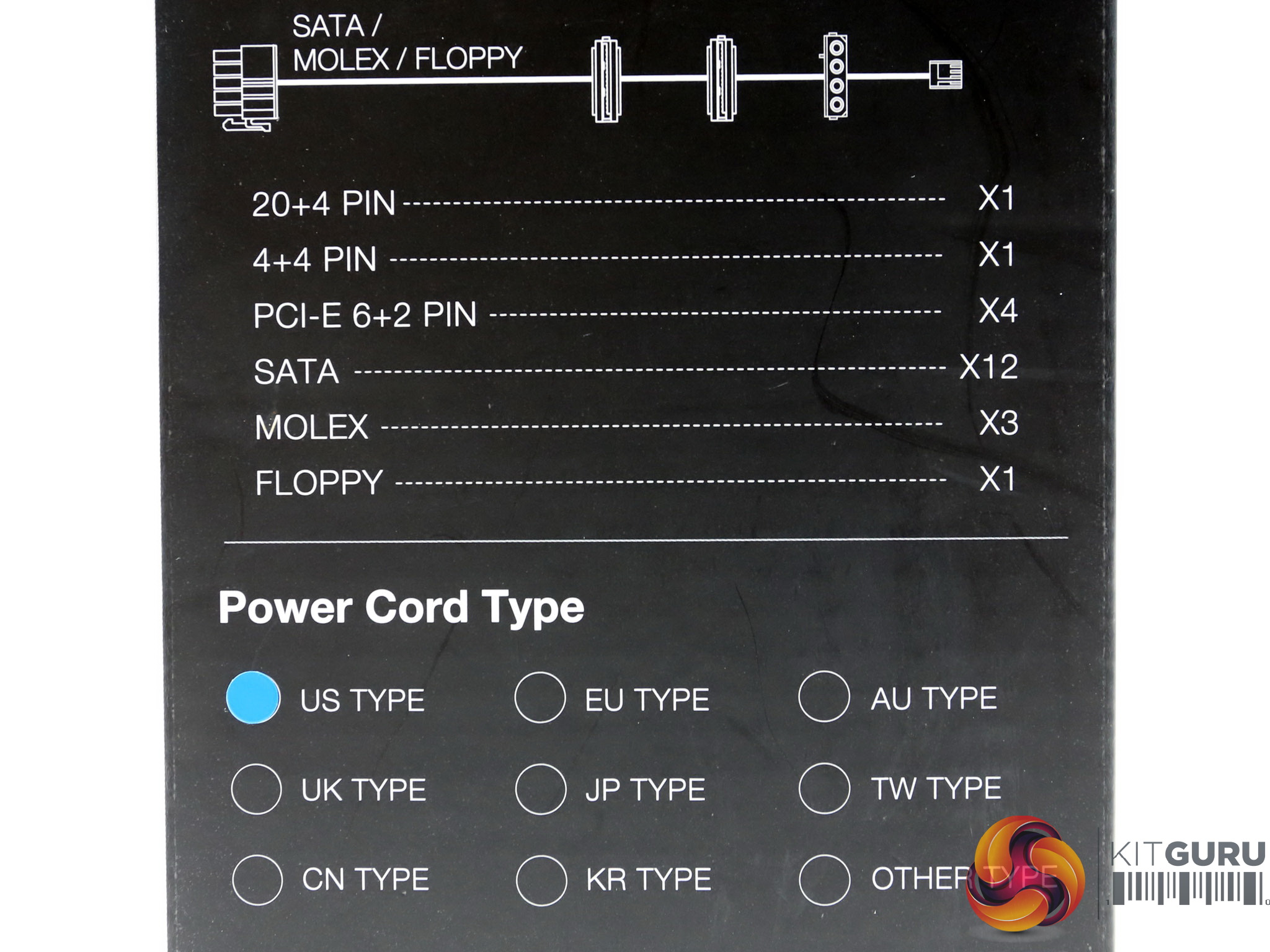
At the sides of the box are the efficiency and fan noise curves, along with the power specifications table and a list of the provided cables and connectors. The power cord type is also shown. Our sample shipped with a US-type cord.
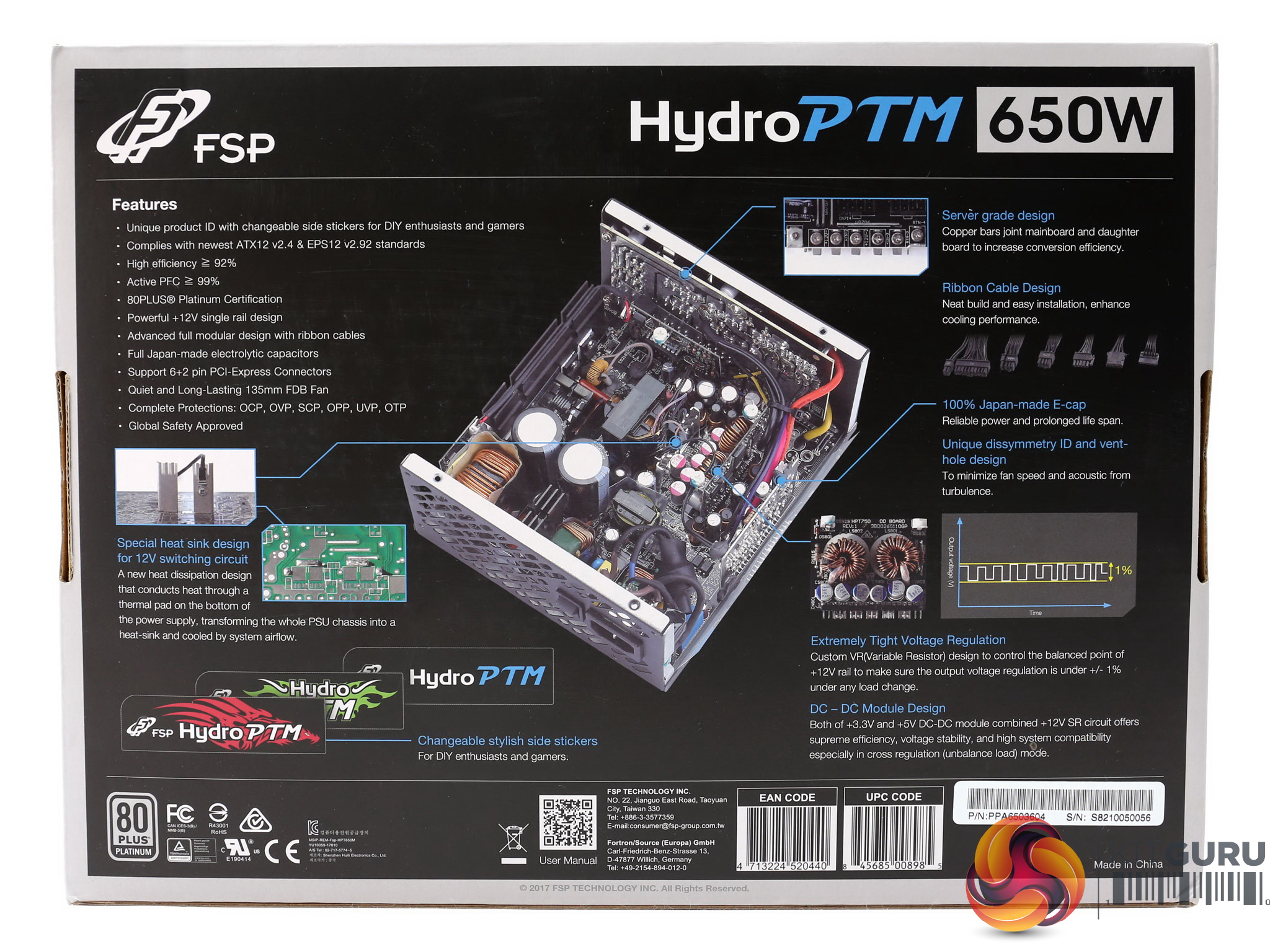
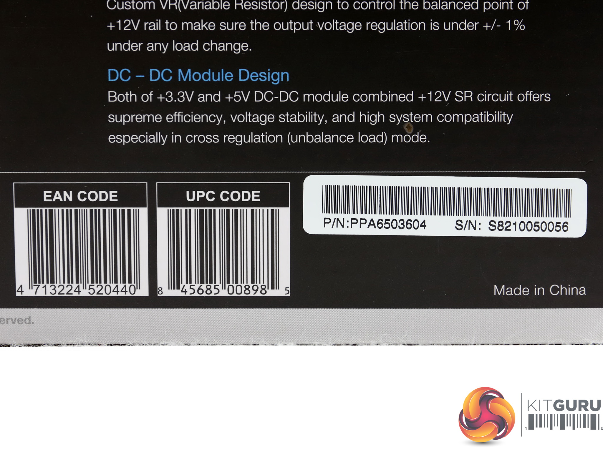
There is an interesting photo at the back of the box, showing the unit's internals. FSP provides a description of the platform's major features and there is a long feature list as well – mentioning some interesting information about the supply.
Another feature of this product is that it comes with changeable side stickers, since in the bundle FSP includes two spare sets.
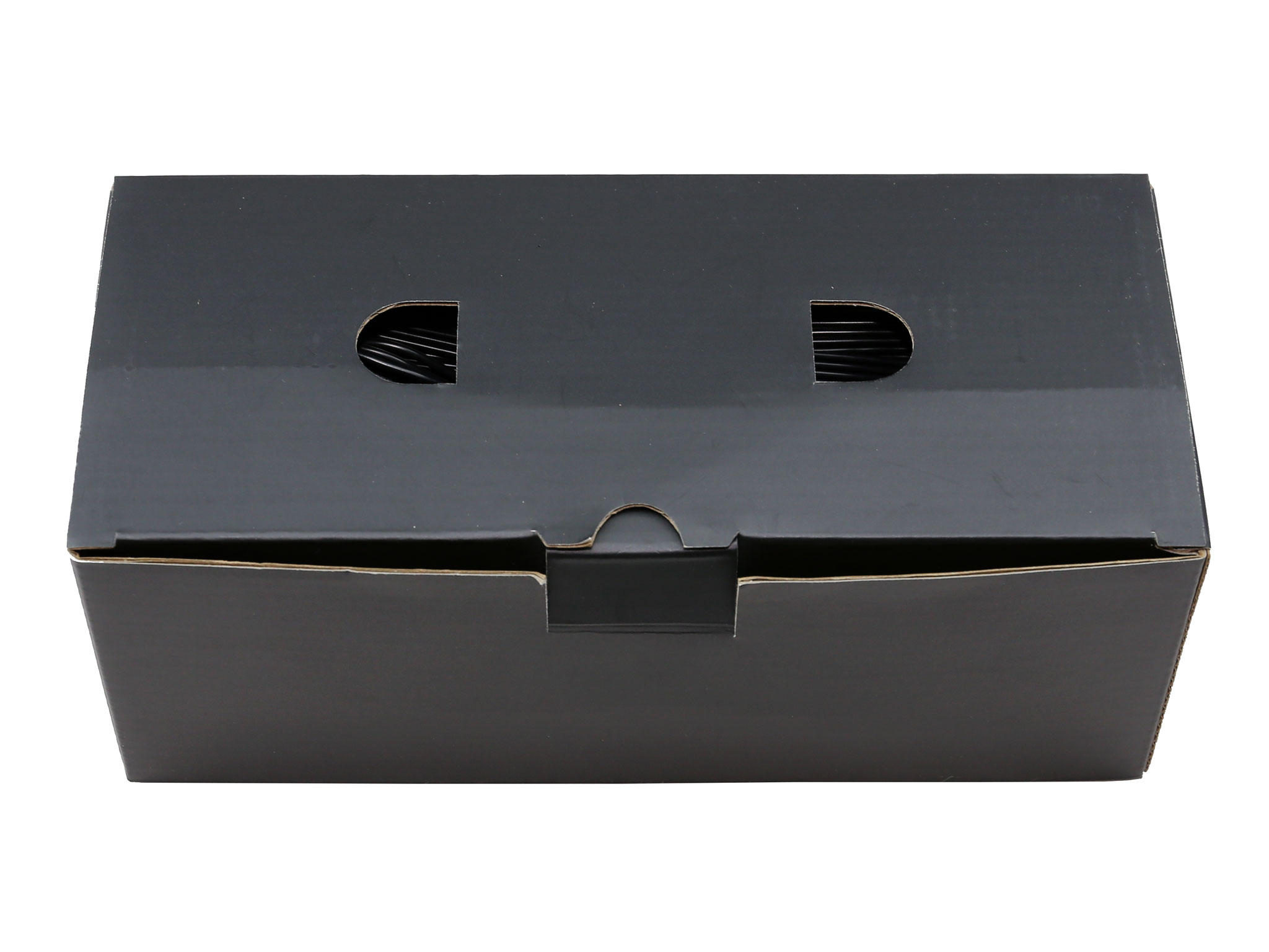
Contents
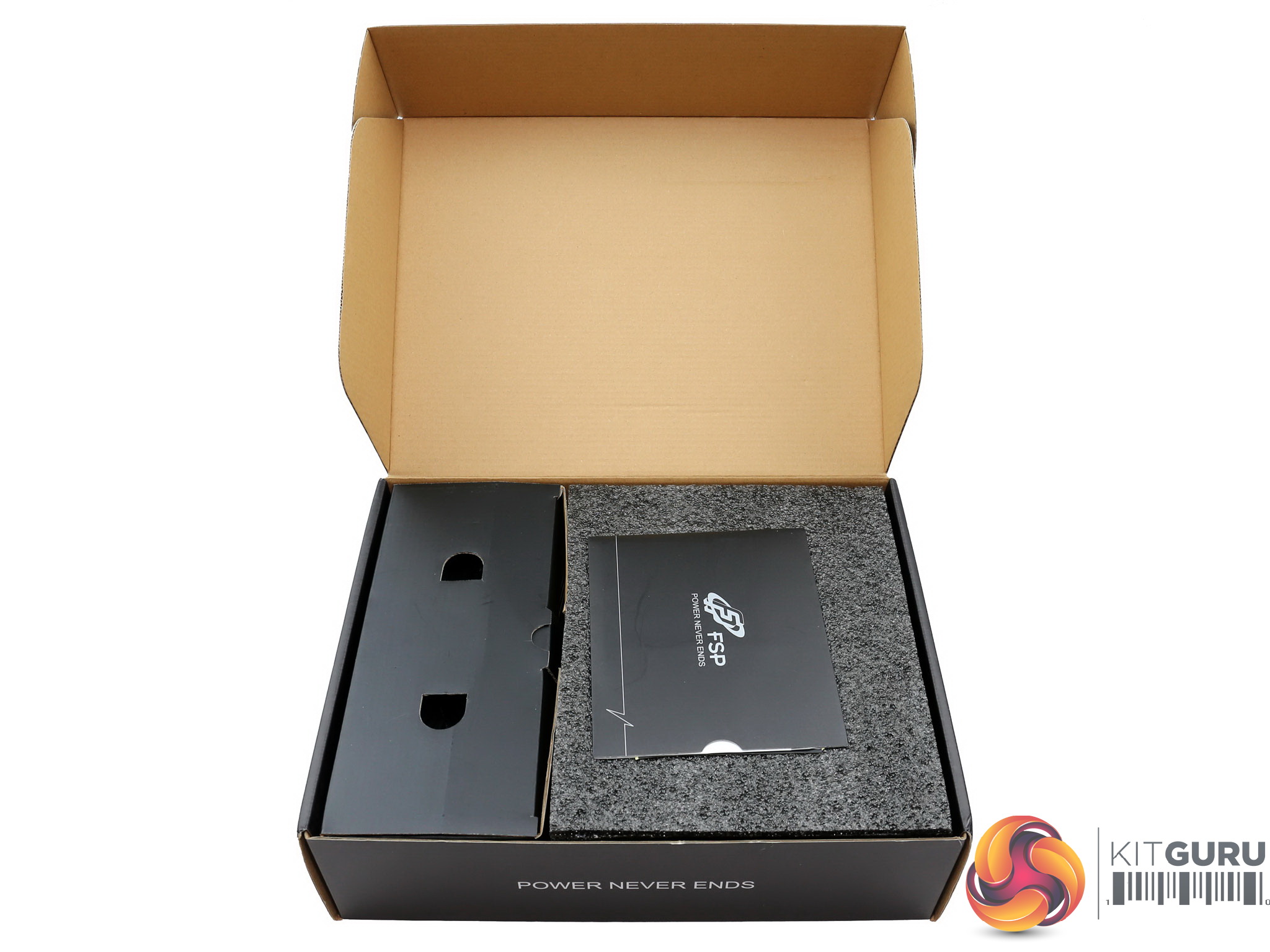
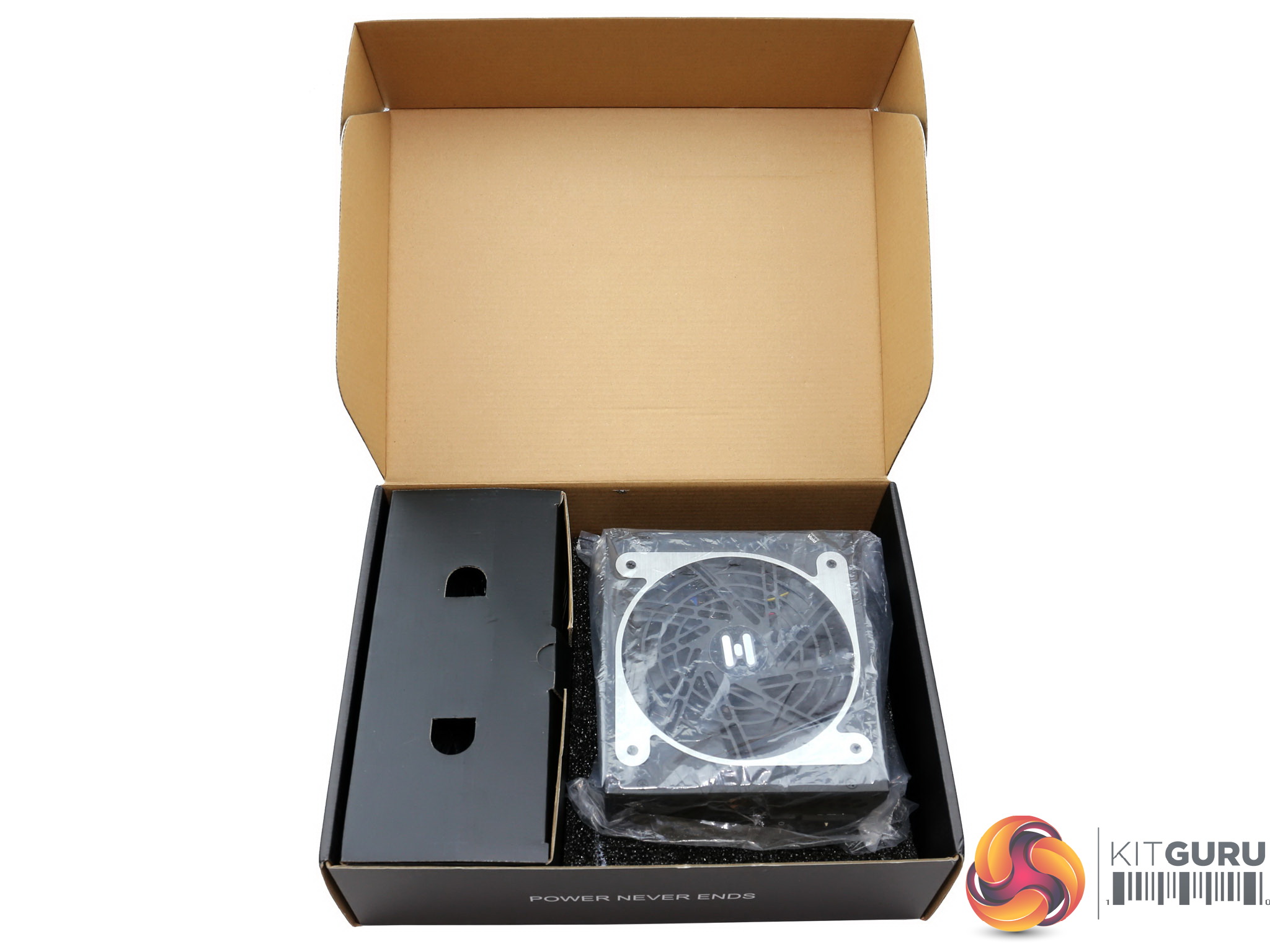
The protection inside the box is good, with packing foam totally surrounding the product – this is also wrapped in plastic.
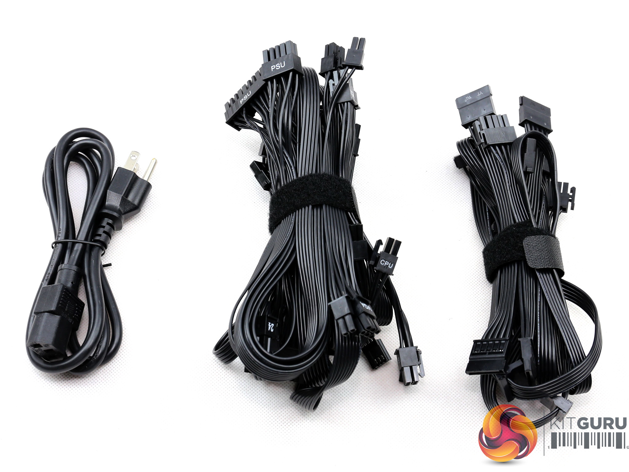
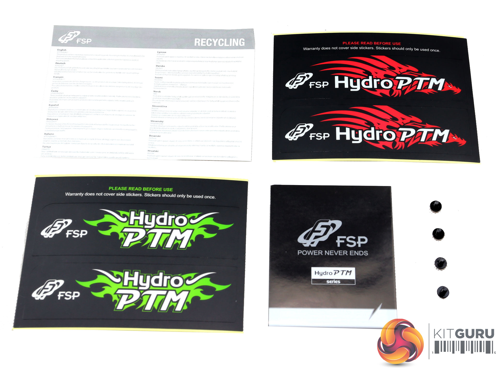
A smaller box contains all cables along with the power cord. The bundle includes the user's manual, a warranty leaflet, two sets of stickers and a set of fixing bolts.
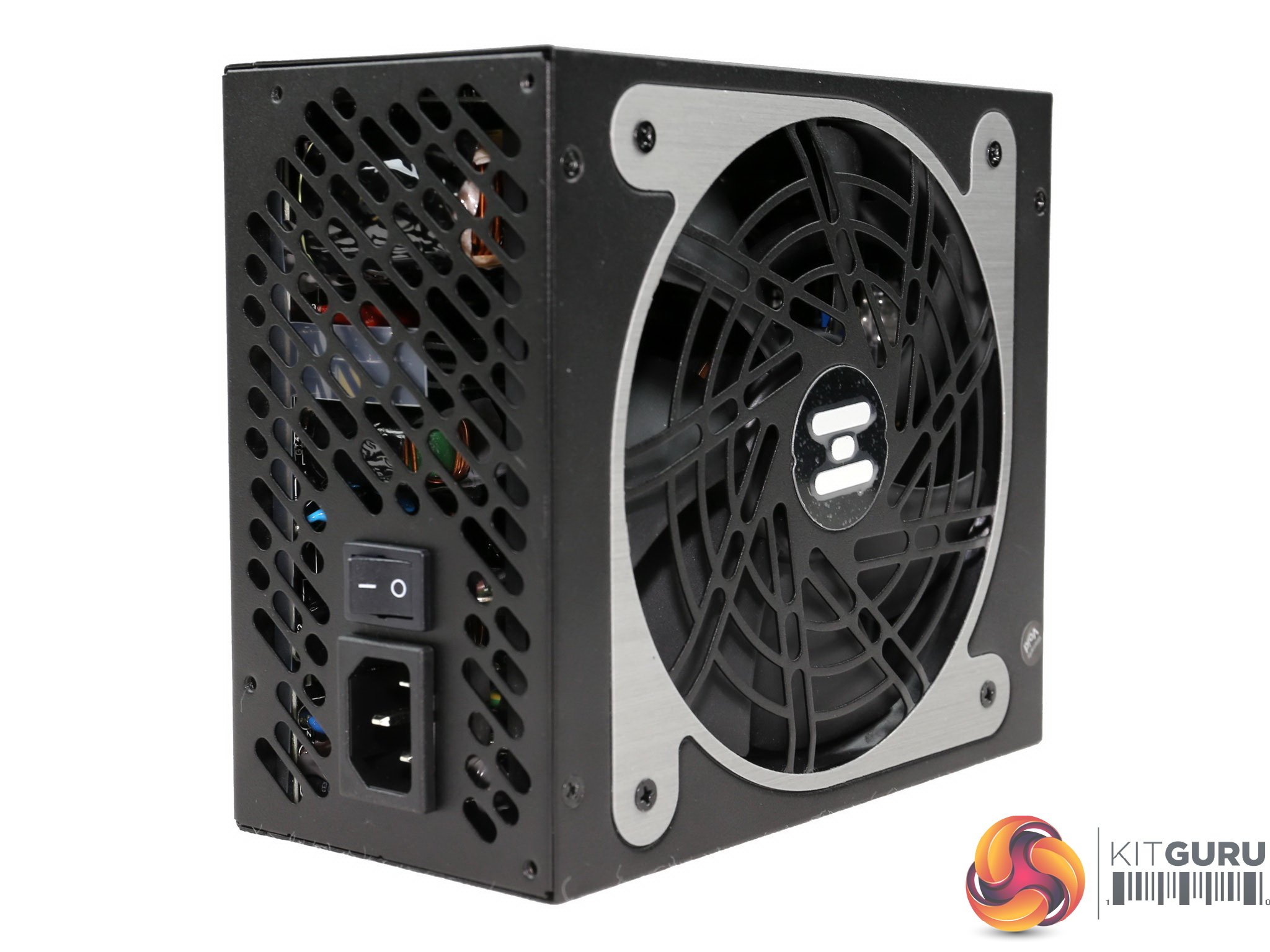
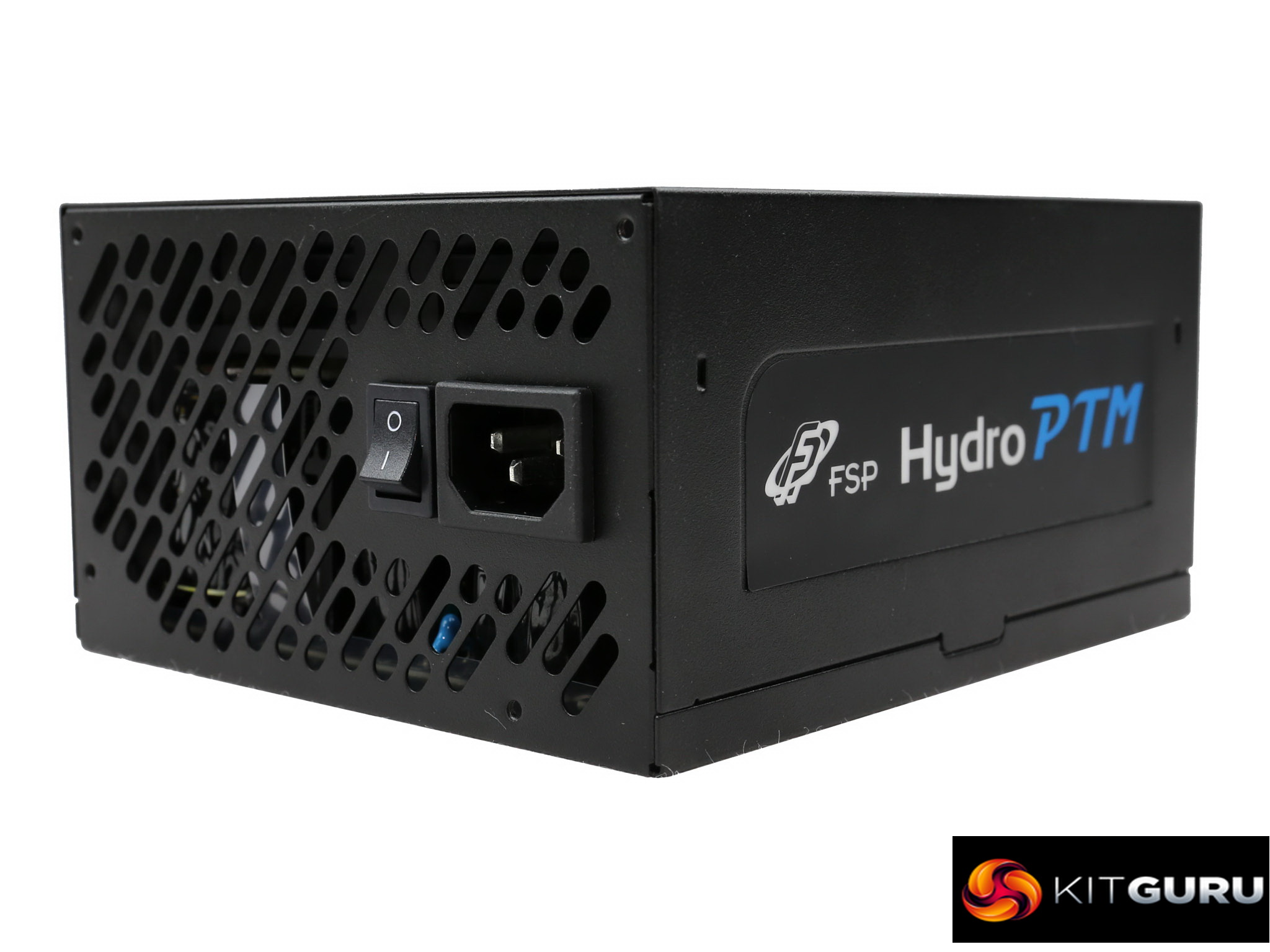
Exterior
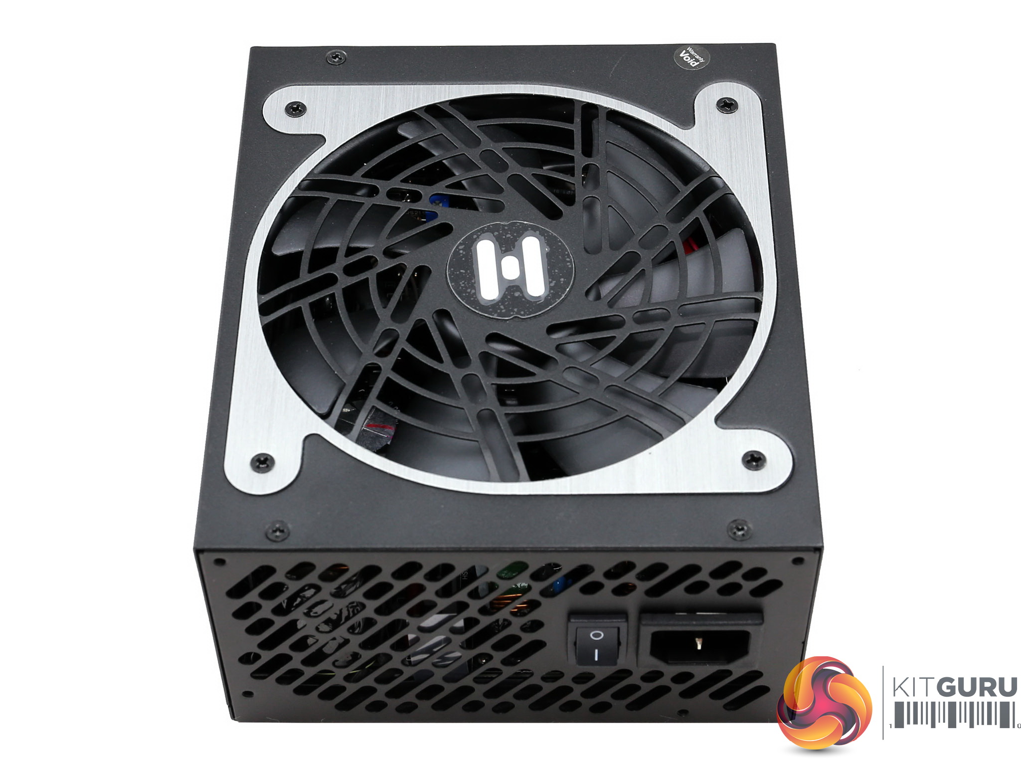
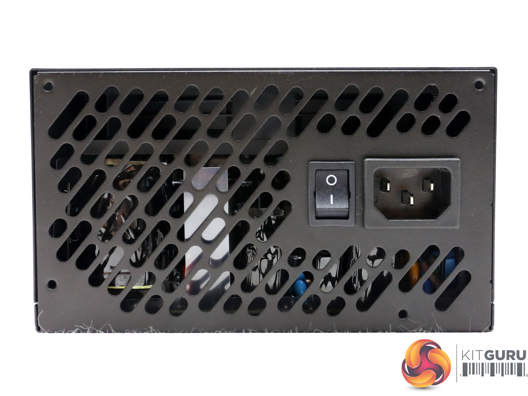
The unit's exhaust doesn't utilize the usual honeycomb design, but the perforations are much larger enhancing the airflow. The small on/off switch is located right next to the AC receptacle.
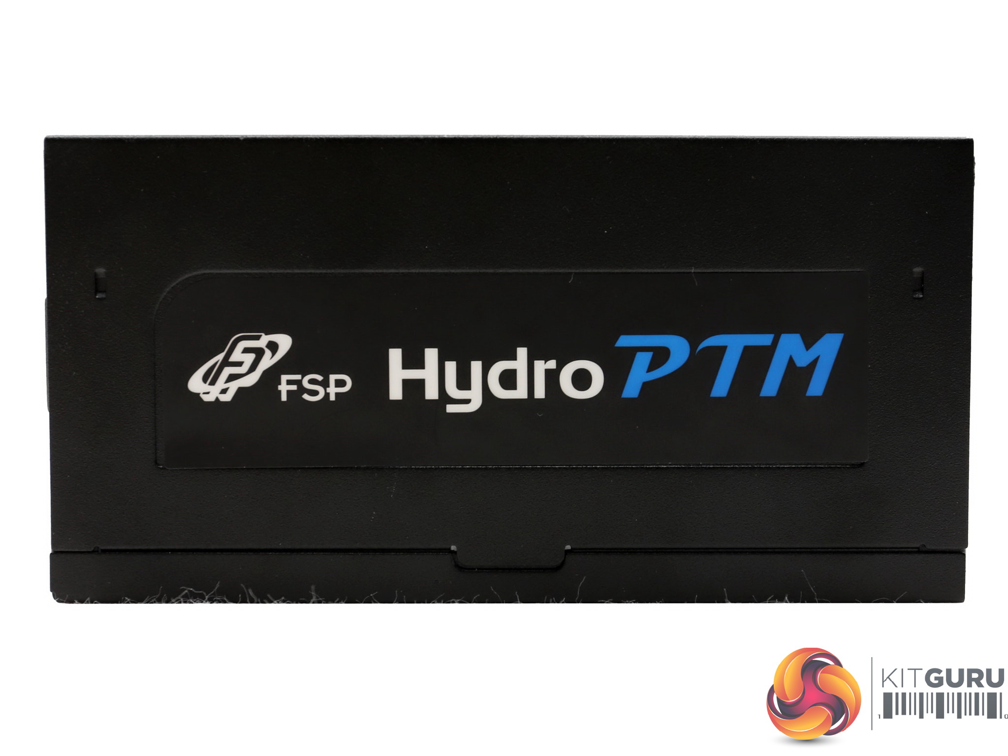
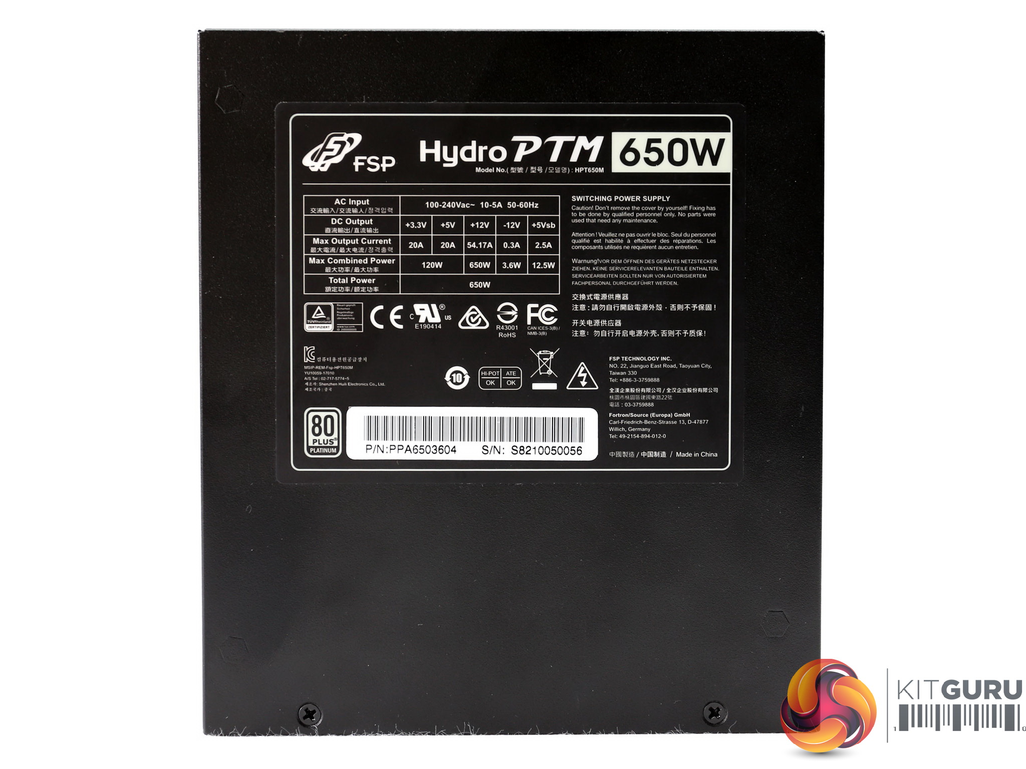
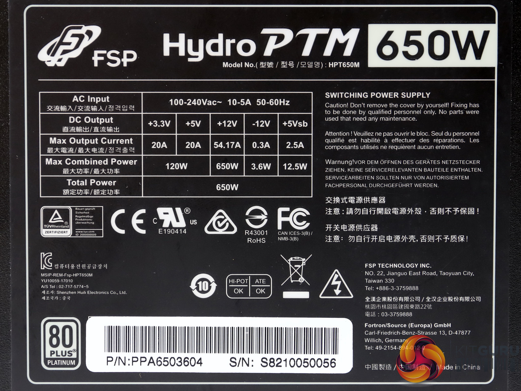
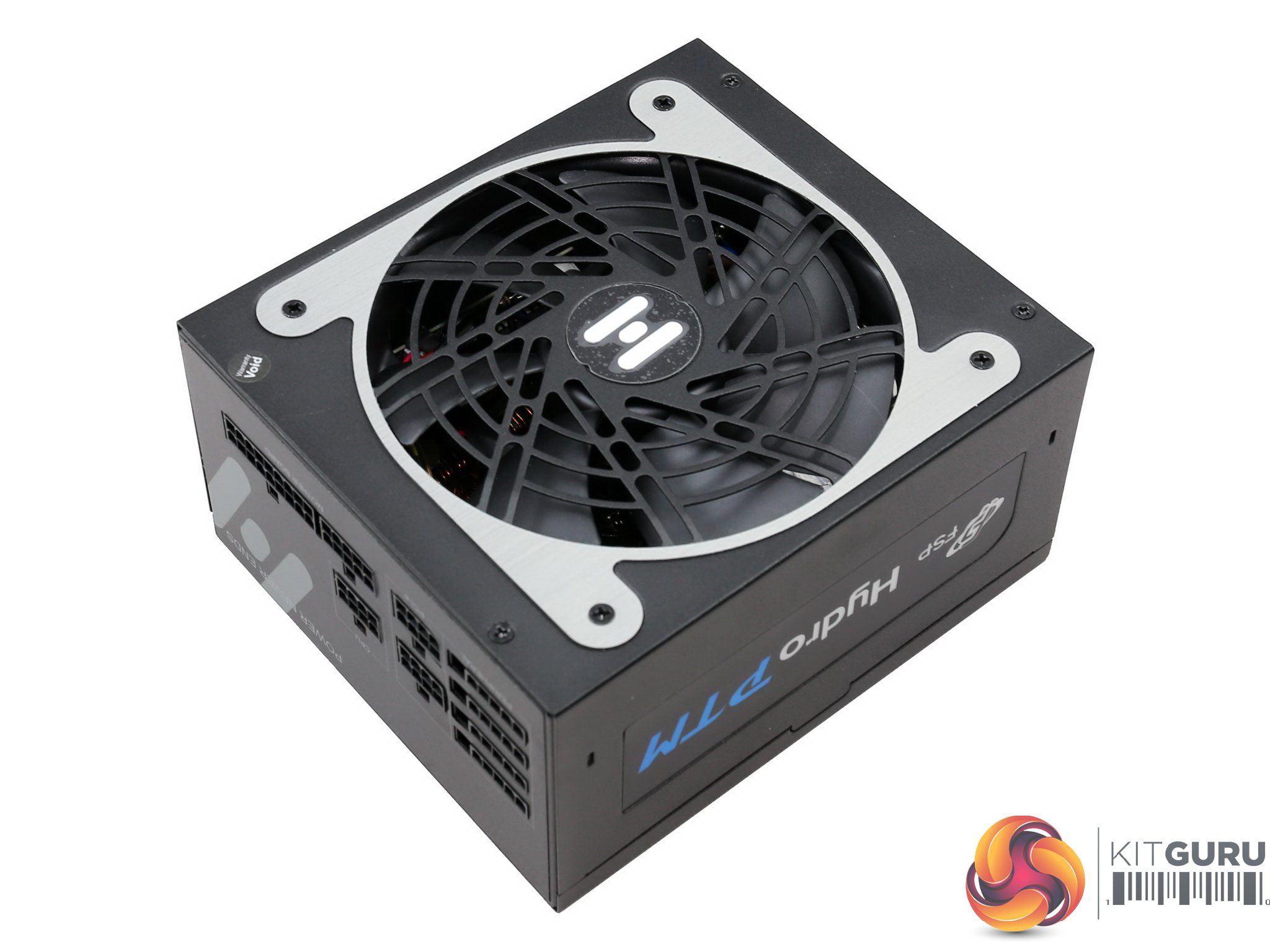
On the sides the stickers depict the line's name, while a large sticker at the bottom side shows the power specifications table along with the product's serial and part numbers.
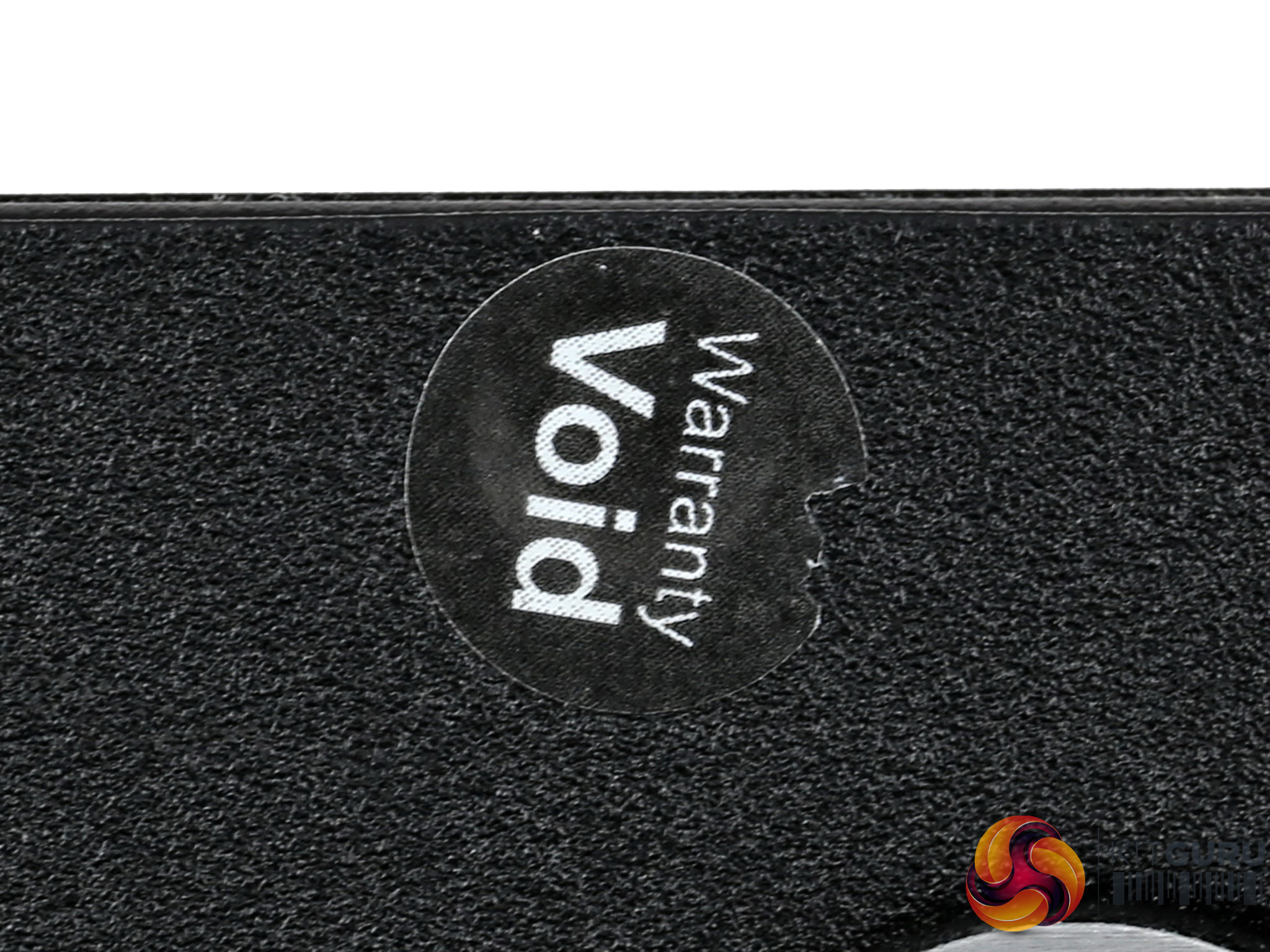
There is a void warranty sticker however FTC (Federal Trade Commission) looks to have a problem with those. Nonetheless, the truth is that it is very dangerous to open a PSU especially if you are not trained in such repairs.
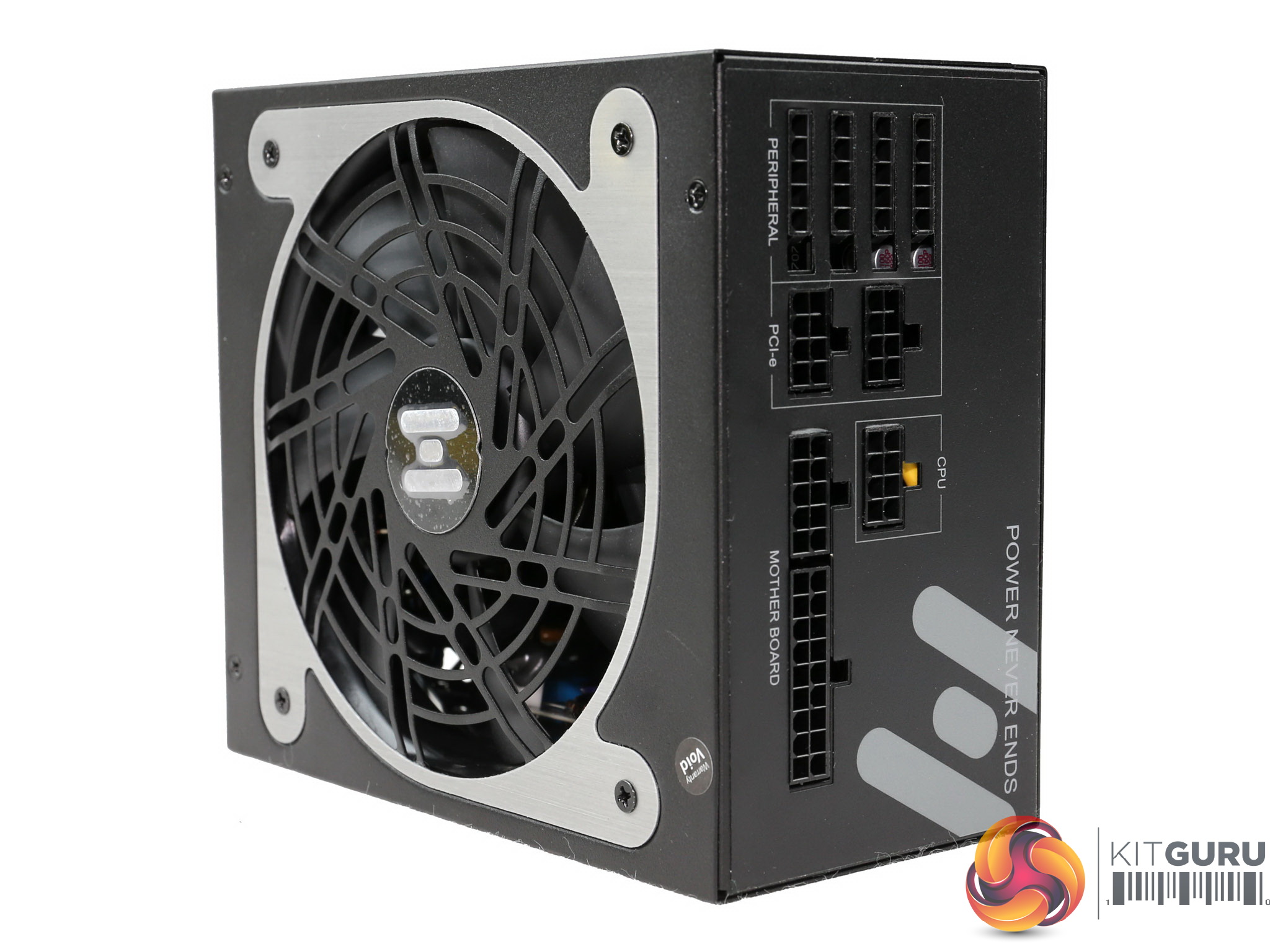
At the rear the modular panel has nine sockets and the sticker covers two more perforations. Apparently the same modular panel cover with the HPT750M is used, to save money and keep the production cost low.
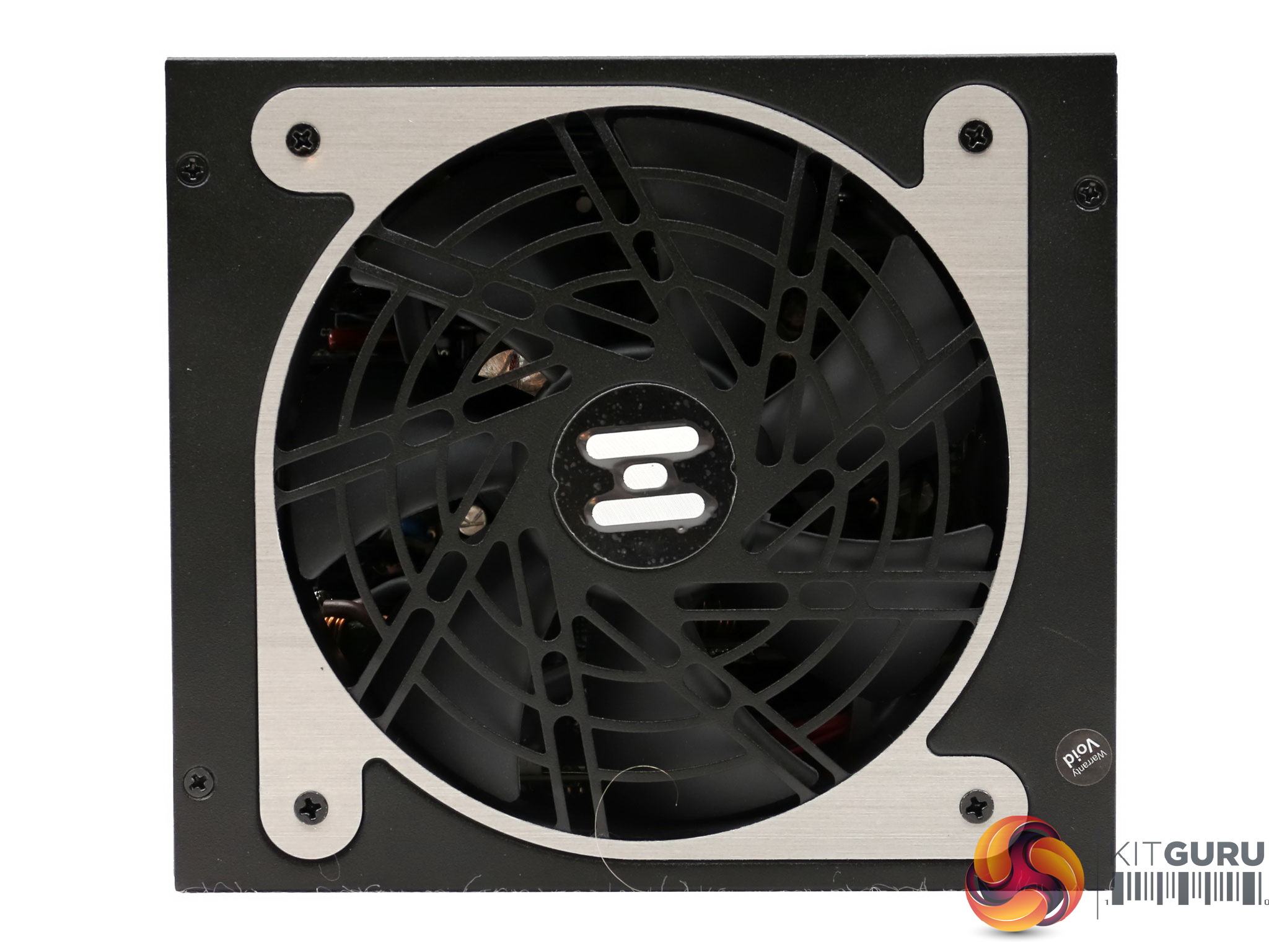
The unit's dimensions are quite large given its 650W capacity. FSP used the same chassis with the HPT750M since it would be expensive to build a new one just for the HPT650M.
|
General Data |
|
|
Manufacturer (OEM) |
FSP |
|
Platform Model |
PTM |
|
Primary Side |
|
|
Transient Filter |
4x Y caps, 2x X caps, 2x CM chokes, 1x MOV, 1x SEN013DG |
|
Inrush Protection |
NTC Thermistor & relay |
|
Bridge Rectifier(s) |
1x GBJ1506 (600V, 15A @ 100°C) |
|
APFC MOSFETS |
2x STMicroelectronics STFH24N60M2 (650V, 12A @ 100°C, 0.19Ohm) |
|
APFC Boost Diode |
1x STMicroelectronics STPSC6H065D (650V, 6A @ 110°C) |
|
Hold-up Cap(s) |
2x Nichicon GG (450V, 270uF each or 540uF combined, 2000h @ 105°C) |
|
Main Switchers |
2x STMicroelectronics STFH24N60M2 (650V, 12A @ 100°C, 0.19Ohm) |
|
Driver IC |
1x Silicon Labs Si8233BD |
|
APFC Controller |
|
|
Resonant Controller |
Champion CM6901T2X |
|
Topology |
Primary side: Half-Bridge & LLC Resonant Controller |
|
Secondary Side |
|
|
+12V MOSFETS |
2x Toshiba TPHR85 04PL (SOP Advance Series, 40V, 150A @ 25C, 0.85 mOhm) |
|
5V & 3.3V |
DC-DC Converters: 6x Infineon BSC0901NS (30V, 94A @ 100°C, 1.9mOhm) |
|
Filtering Capacitors |
Electrolytics: 6x KZE (1-5000h @ 105°C), Rubycon ZLH (6-10000h @ 105°C) |
|
Supervisor IC |
SITI PS223 (OCP, OTP, OVP, UVP, SCP, PG) |
|
Fan Model |
Protechnic Electric MGA13512HF-A25 (135mm, 12V, 0.28A, FDB) |
|
5VSB Circuit |
|
|
Rectifier |
International Rectifier IRFR1018E (60V, 56A @ 100°C, 8.4 mOhm) |
|
Standby PWM Controller |
Power Integrations SC1225K |
This is a modern platform however the design is not clean since a bunch of cables, instead of PCB traces, are used for power transfer – blocking this way, in a degree at least, the airflow.
We don't like seeing many cables inside contemporary designs and FSP should follow the lead of other OEMs who have found ways to minimize their use.
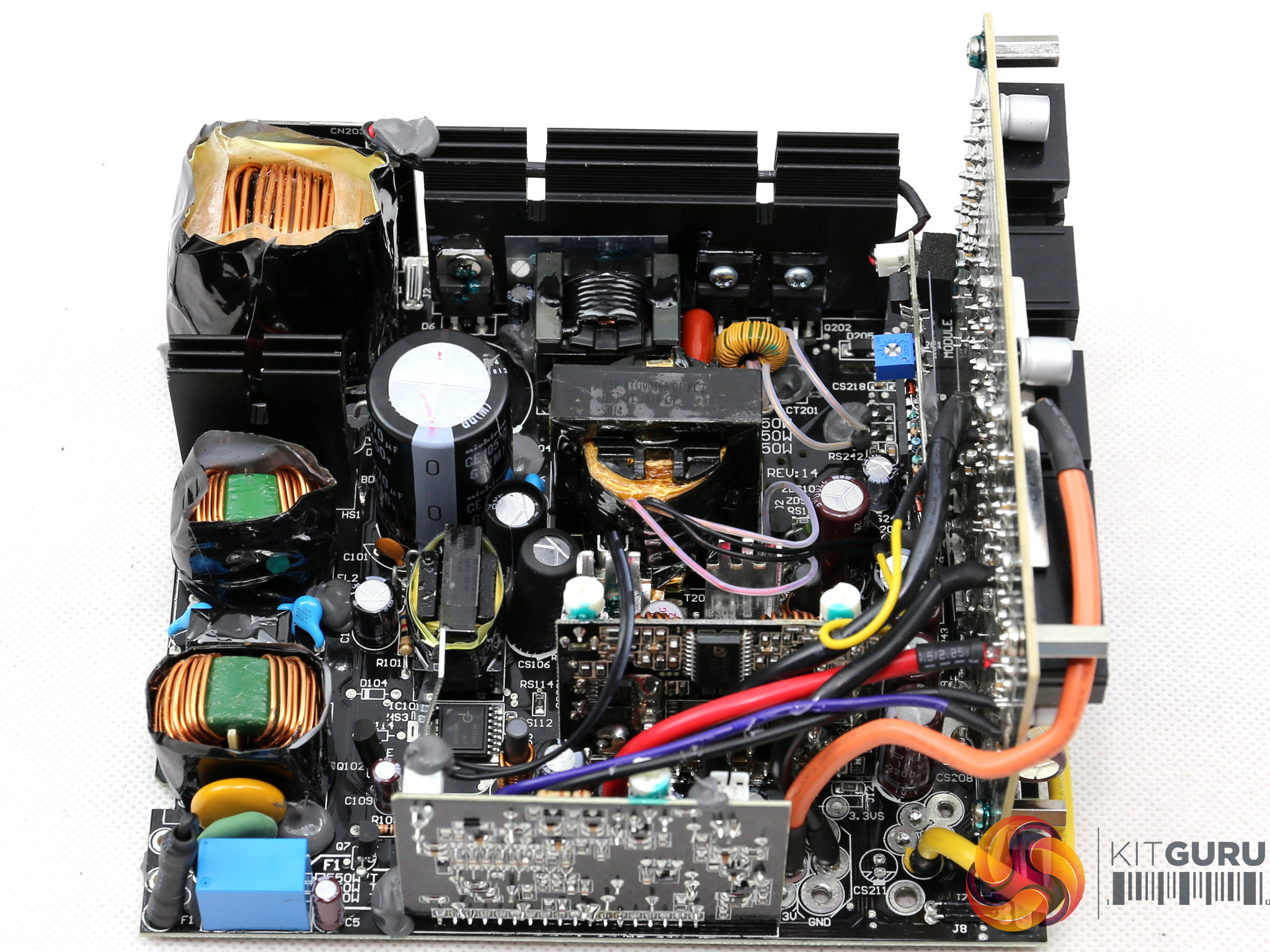
In the primary side a half-bridge topology is used along with an LLC resonant converter, while in the secondary side two FETs regulate the +12V rail and a couple of voltage regulation modules handle the minor rails.
The filtering caps are provided by both Japanese and Taiwanese manufacturers, while the fan is of very high quality.
As usual, the transient filter consists of two parts. It includes in total four Y and two X caps along with a pair of CM chokes, an MOV and a SEN013DG disconnect IC, which isolates not required circuits (e.g. the APFC converter) during standby, in order to restrict power consumption.
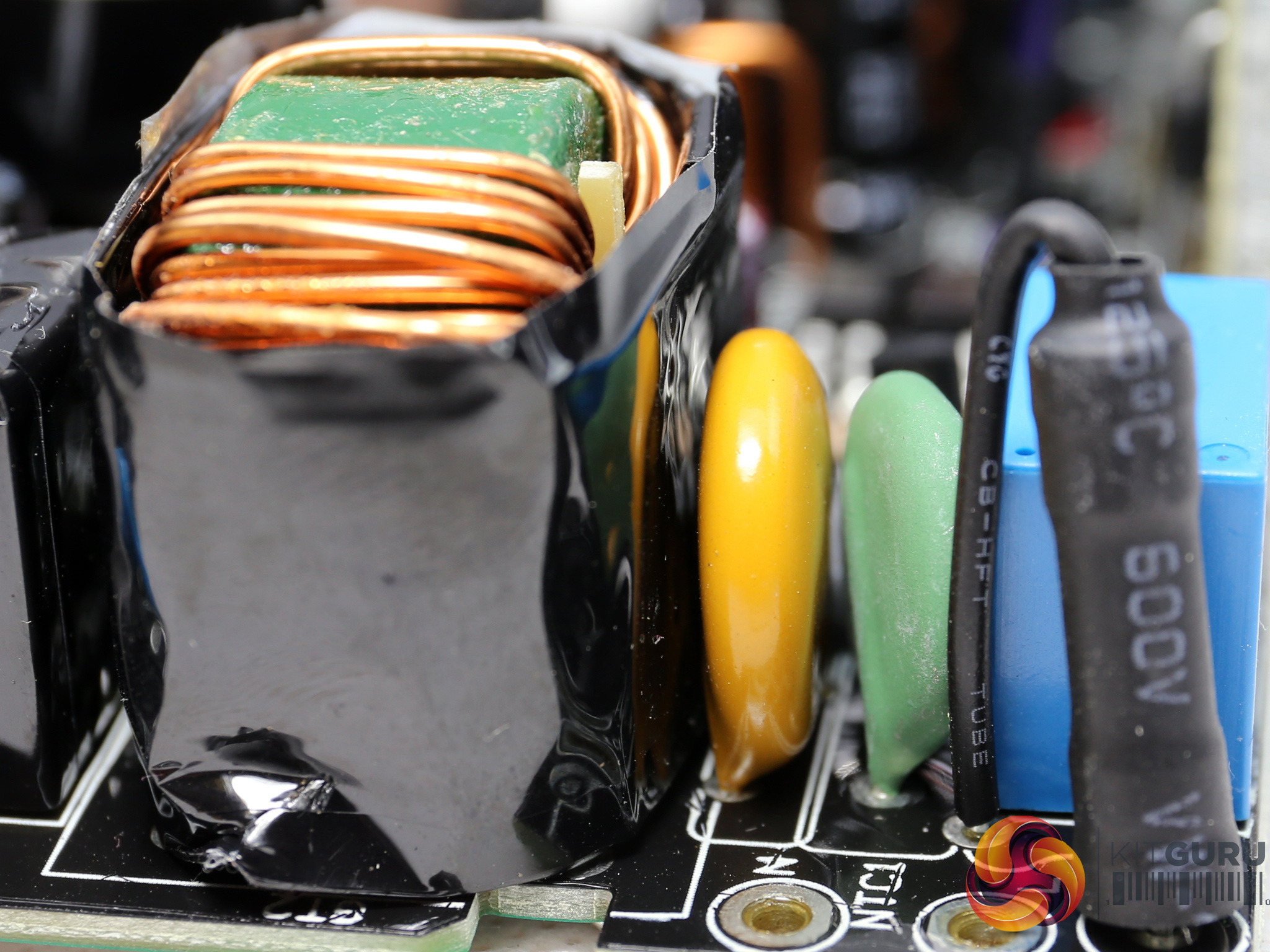
Right next to the MOV we find the NTC thermistor, responsible for protection against high inrush currents.
It is supported by a bypass relay, which makes sure that no energy is lost on the thermistor while the PSU is in operation. Moreover, this relay allows its fast cool down, enhancing the inrush current protection.
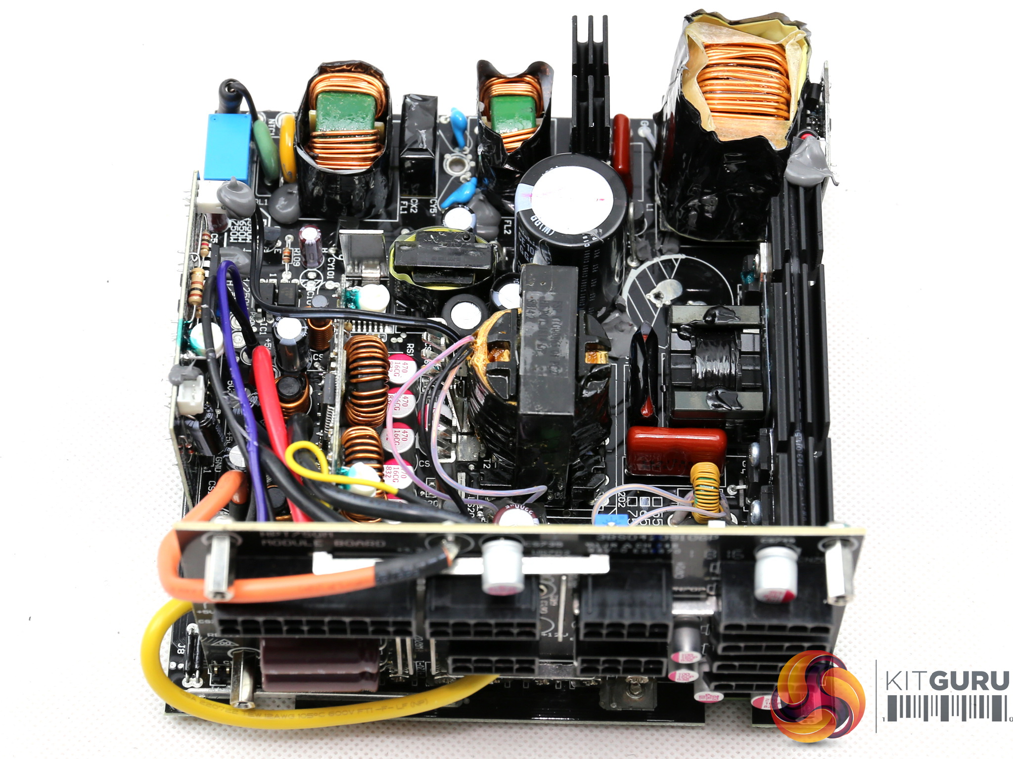
A single bridge rectifier (GBJ1506) is used. In high-end 650W units we usually find two of them, for increased amperage handling and mostly for lowering the power losses since they operate in parallel, so each one has to handle half the amperage.
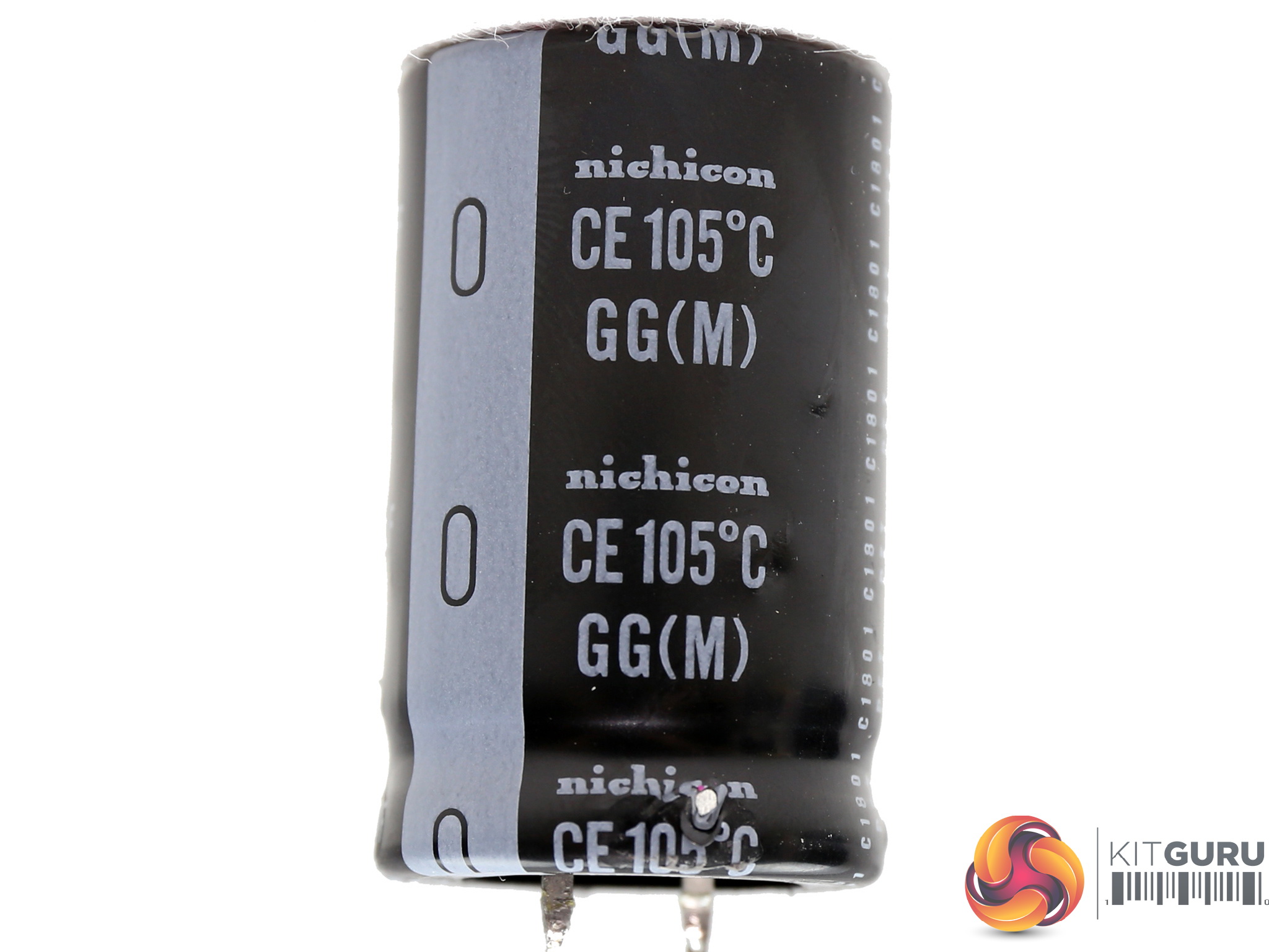
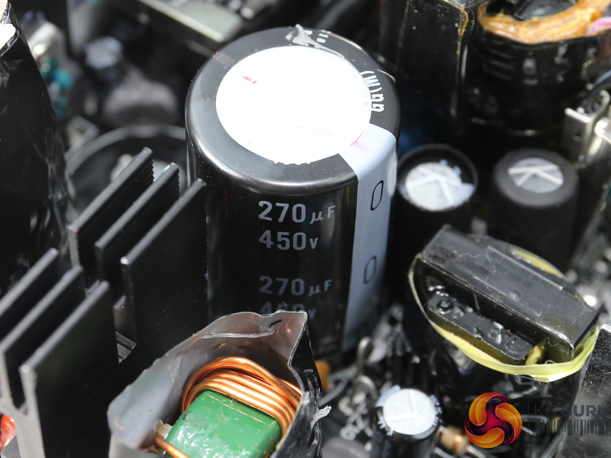
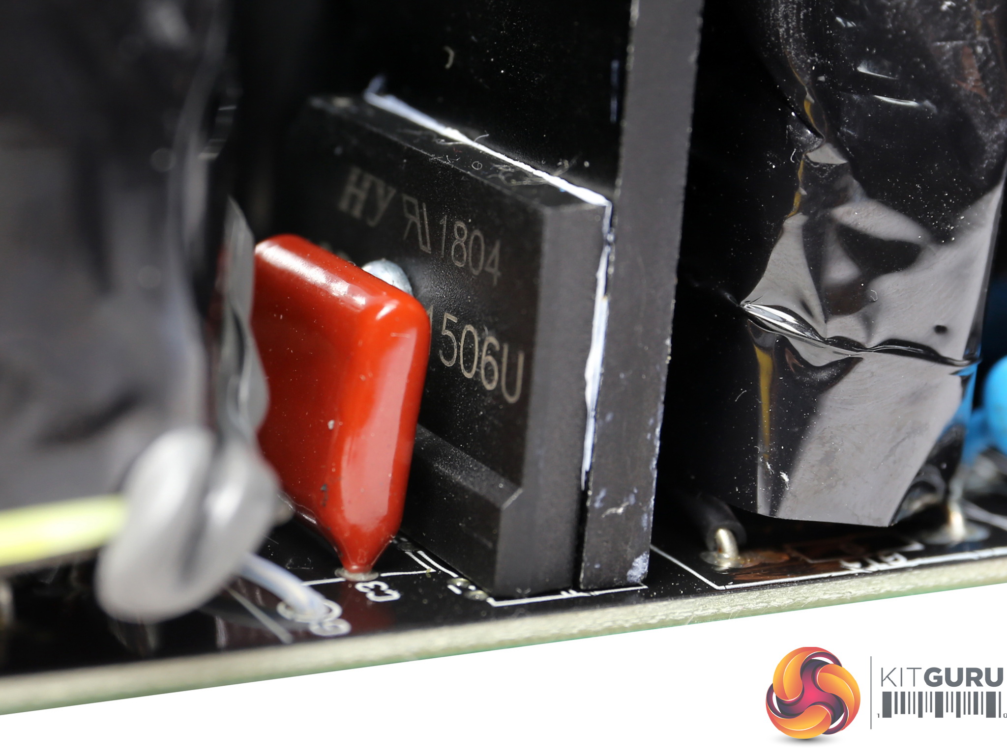
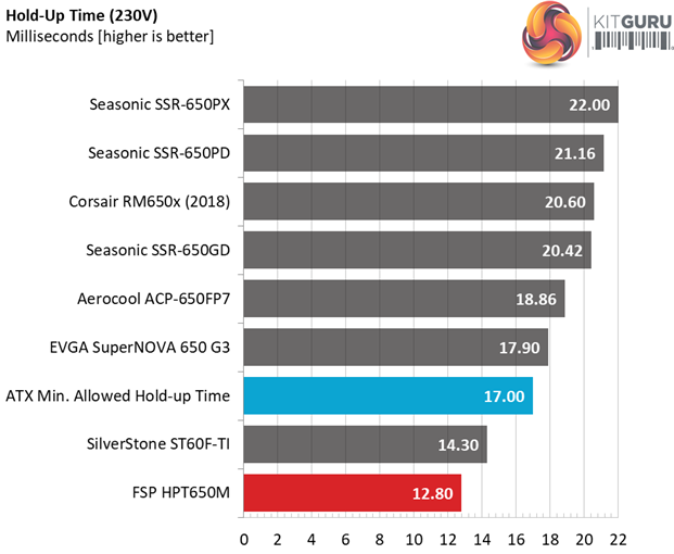
The APFC converter uses two STMicroelectronics STFH24N60M2 FETs and a single STPSC6H065D boost diode, provided by the same manufacturer. Two Nichicon GG bulk caps are installed, with 540uF combined capacity which is not enough to provide a longer than 17ms hold-up time.
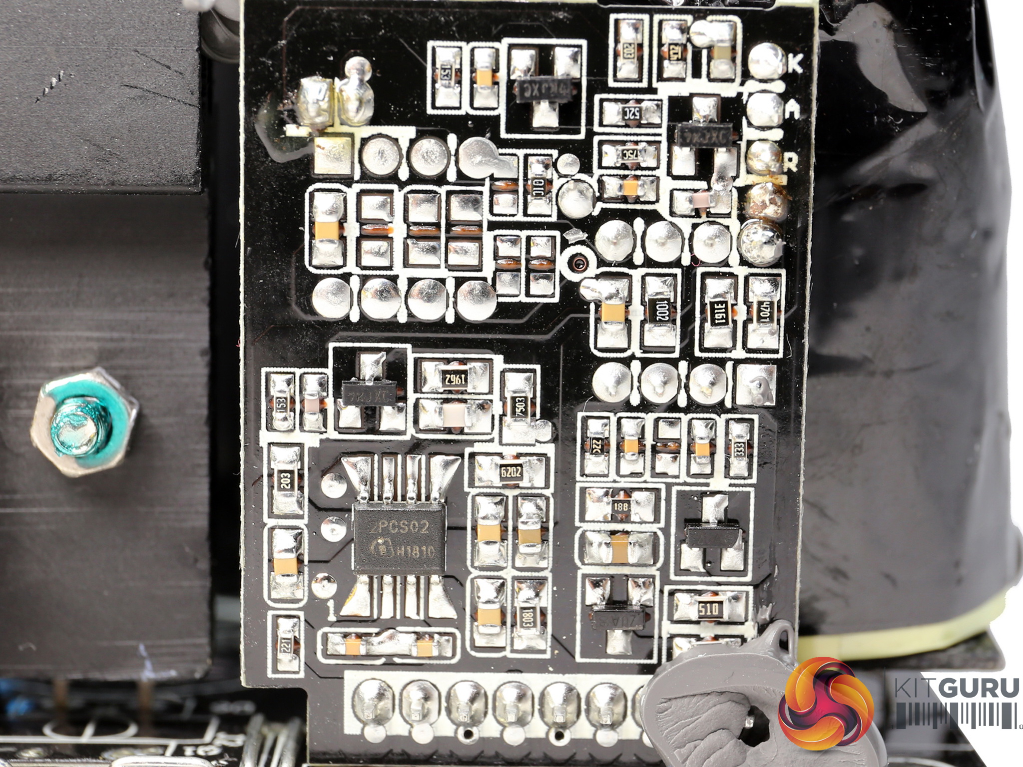
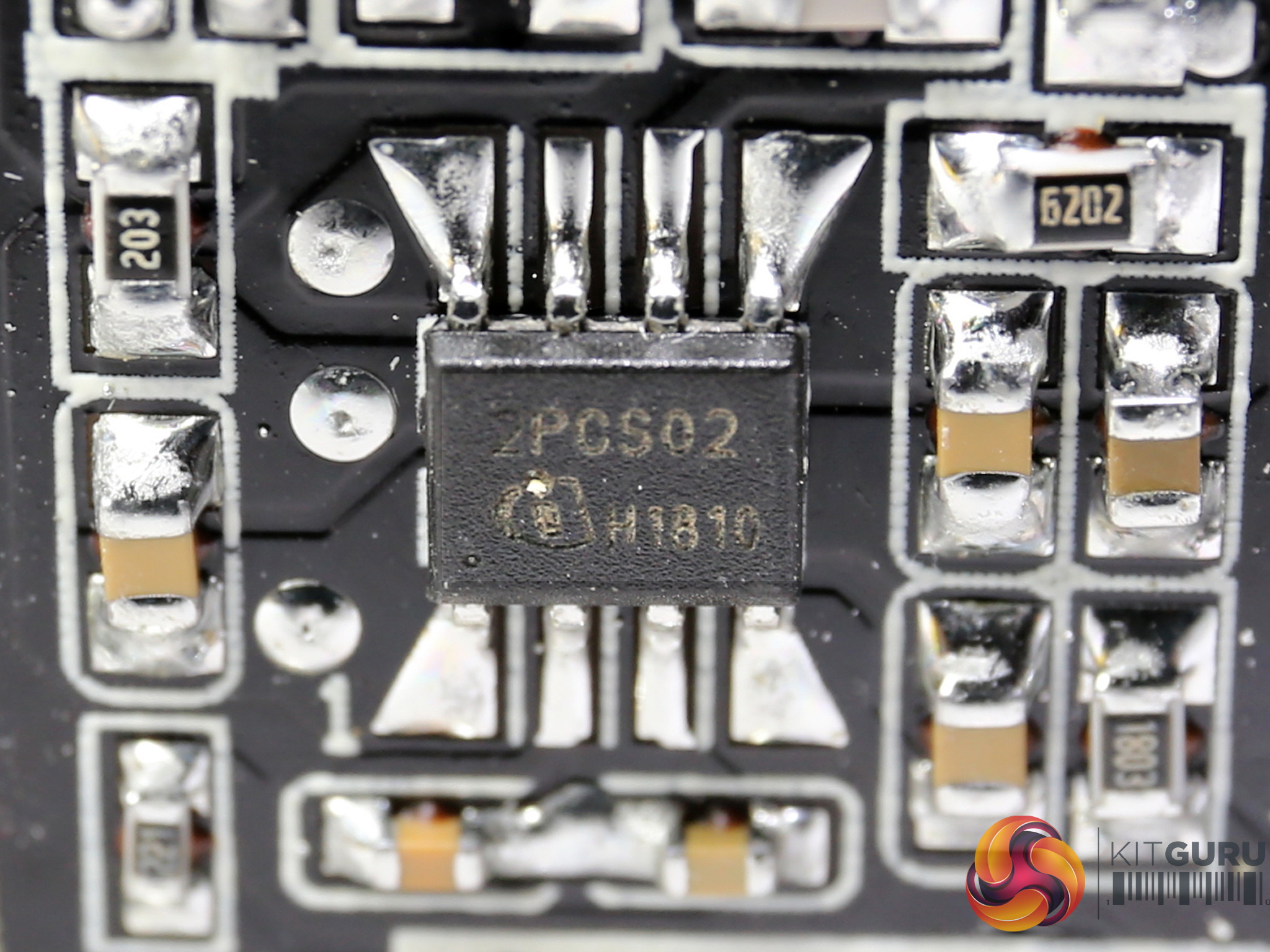
The APFC controller is a Infineon ICE2PCS02, which looks to be supported by a Fairchild KA393 differential comparator.
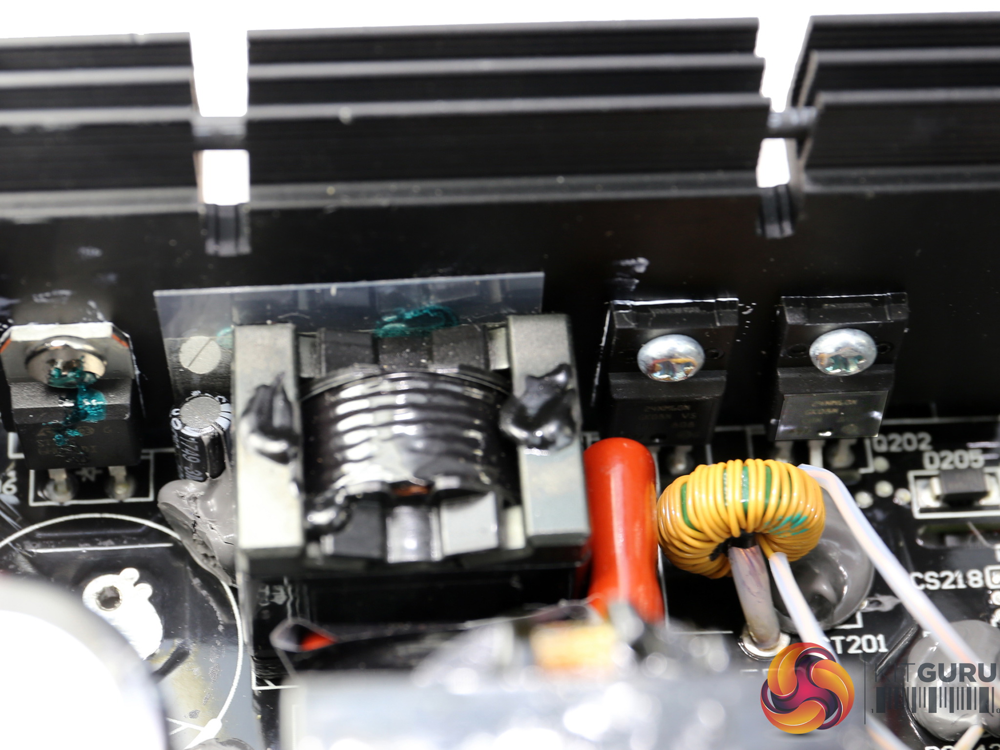
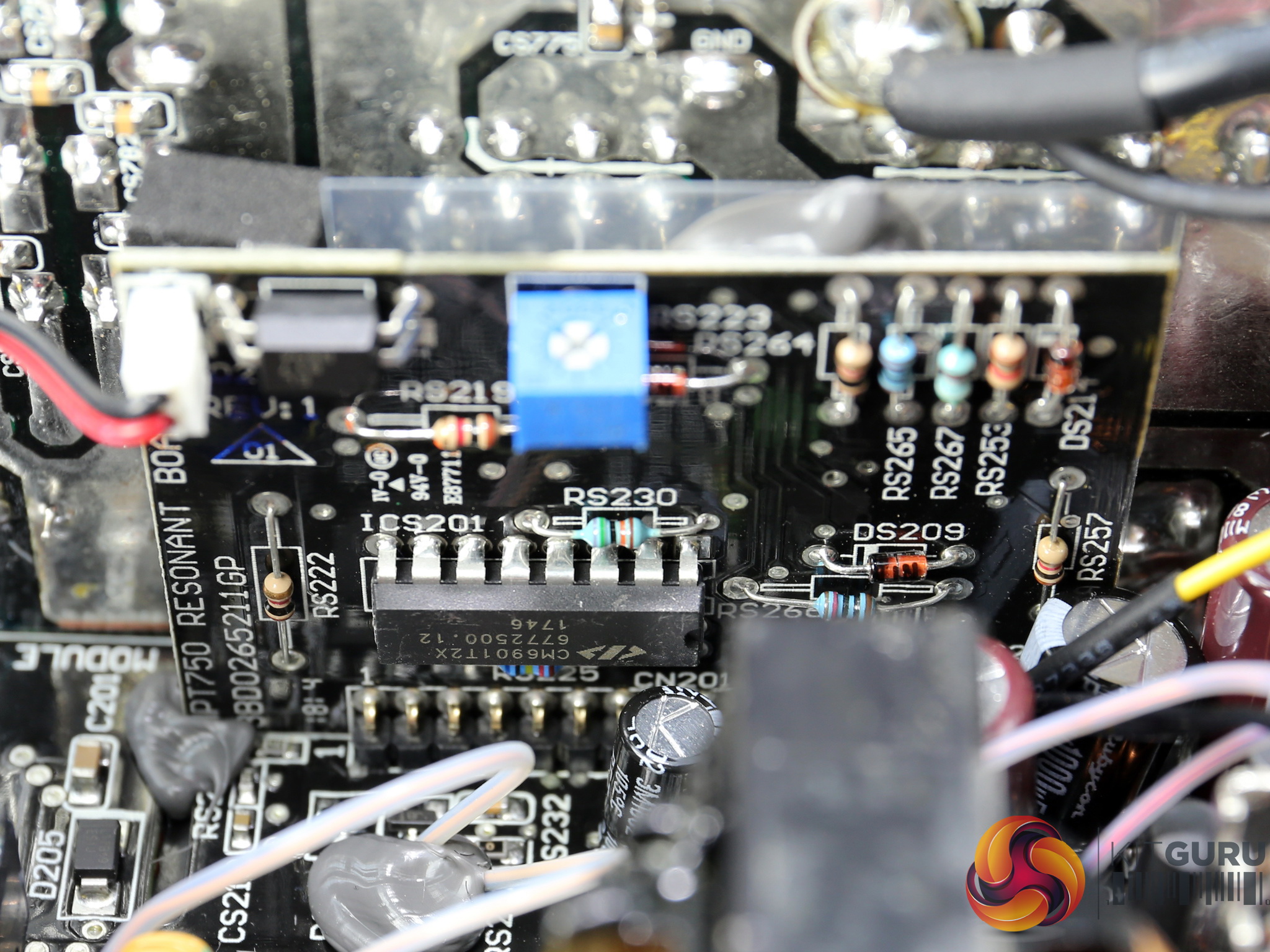
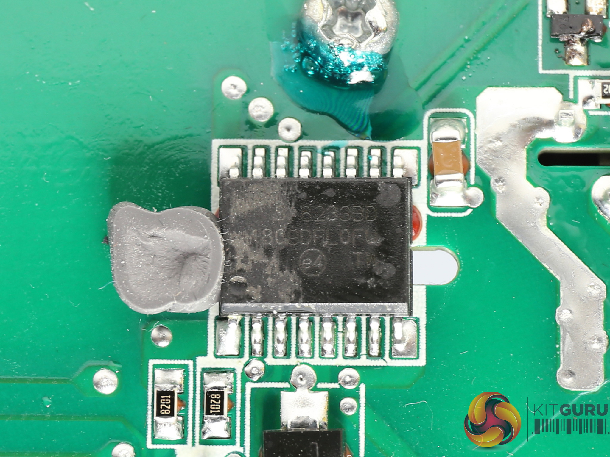
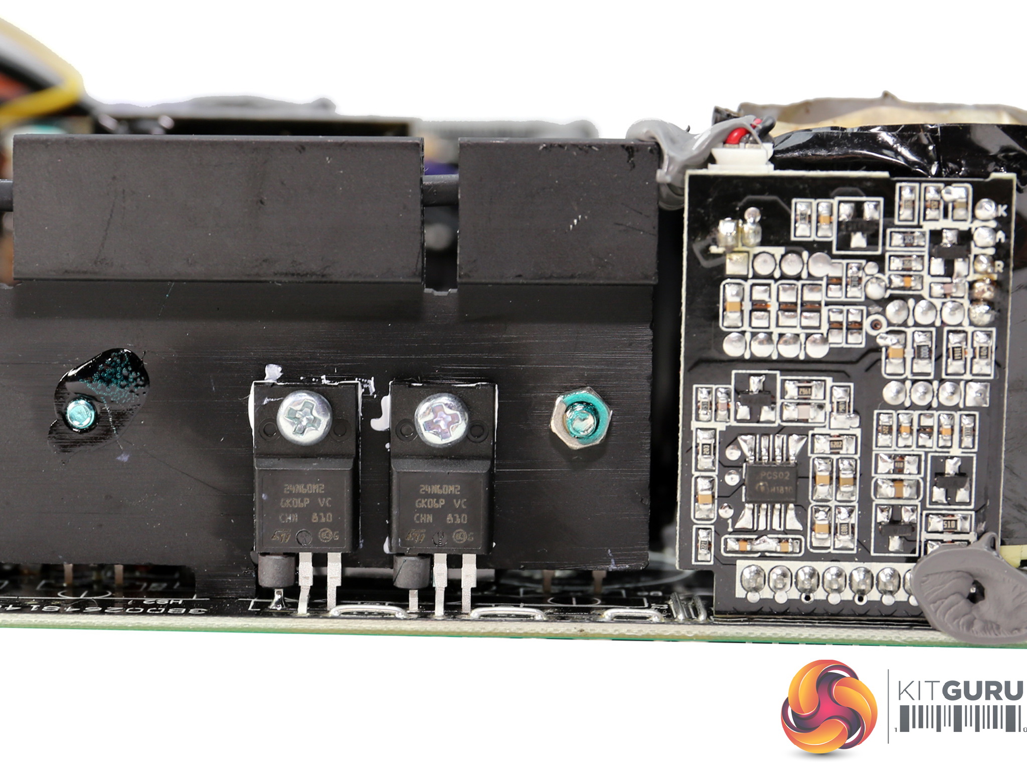
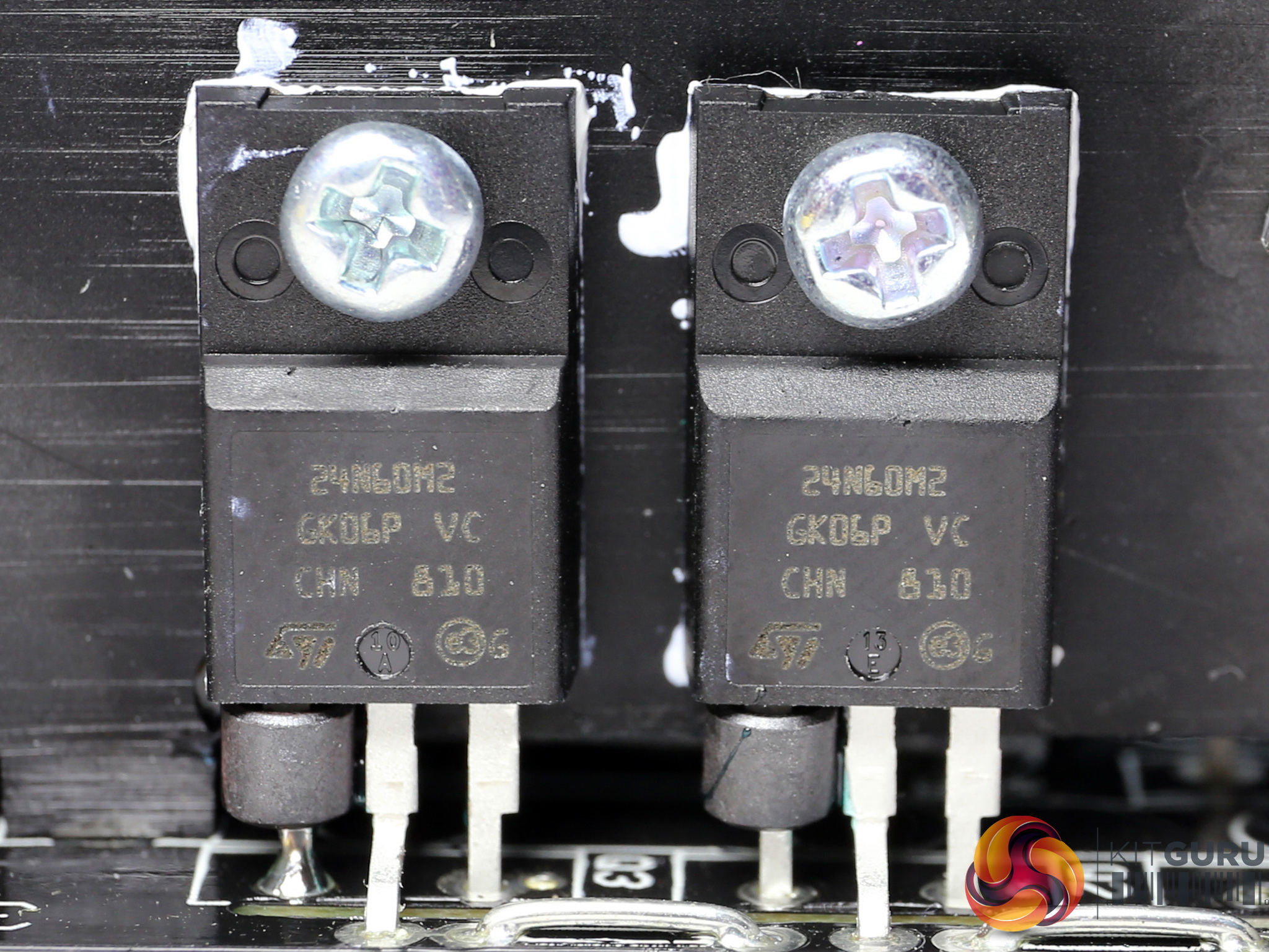
The platform's main switching FETs are a couple of STMicroelectronics STFH24N60M2, arranged into a half-bridge topology. An LLC resonant converter is providing an efficiency boost; its controller is the usual aspect, a Champion CM6901T2X. Finally, the driver IC supporting both main FETs is provided by Silicon Labs (Si8233BD).
![]()
The main transformer.
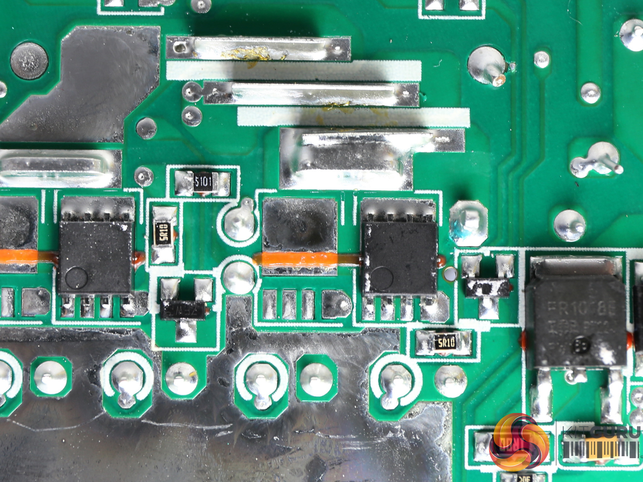
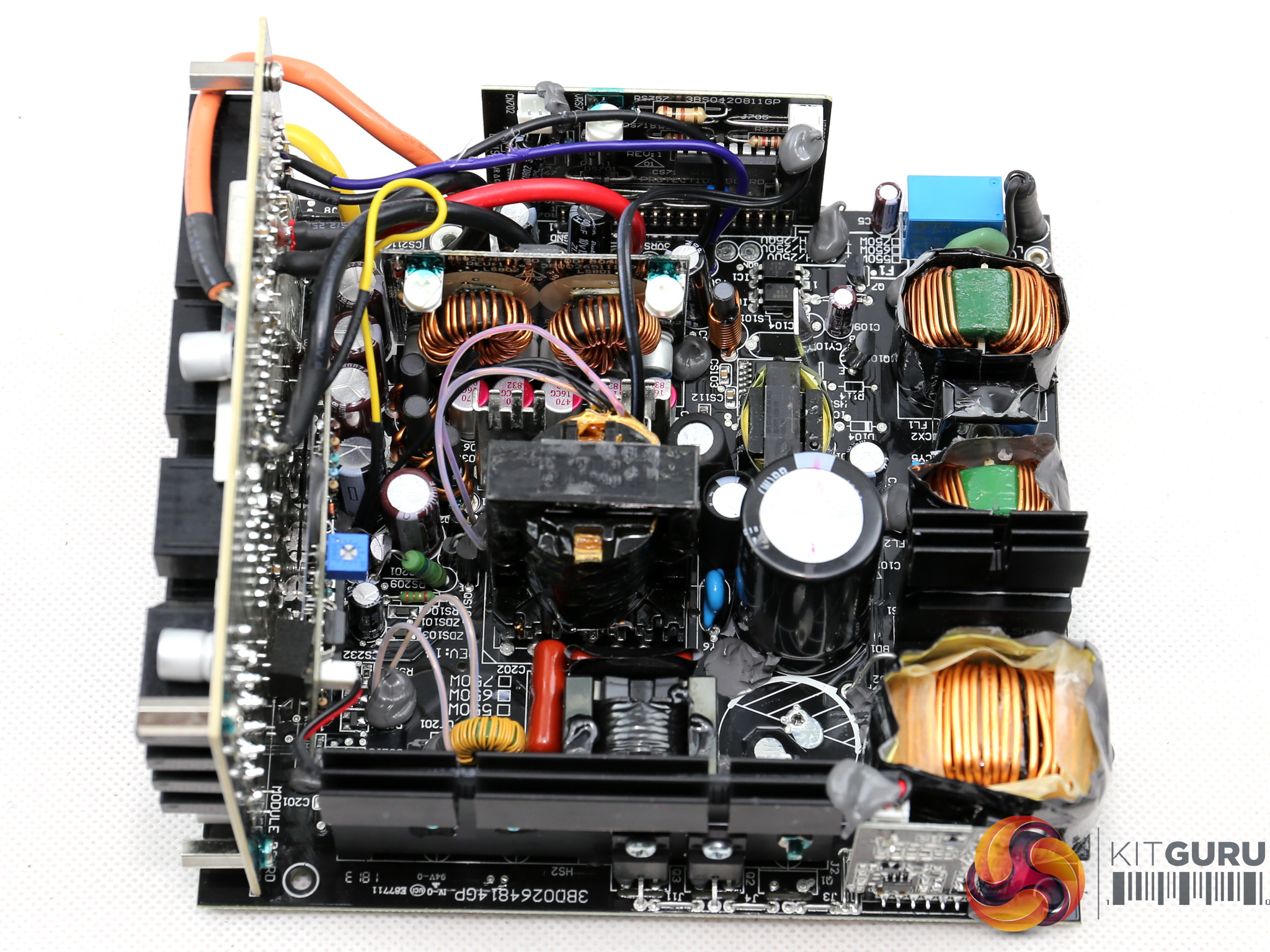
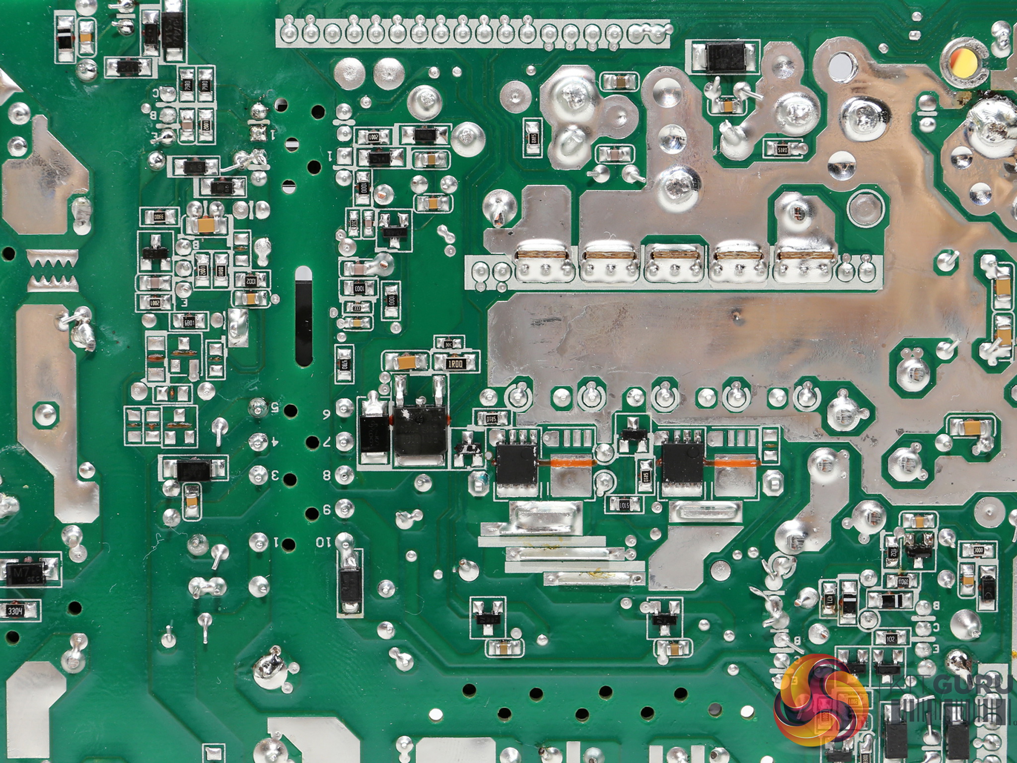
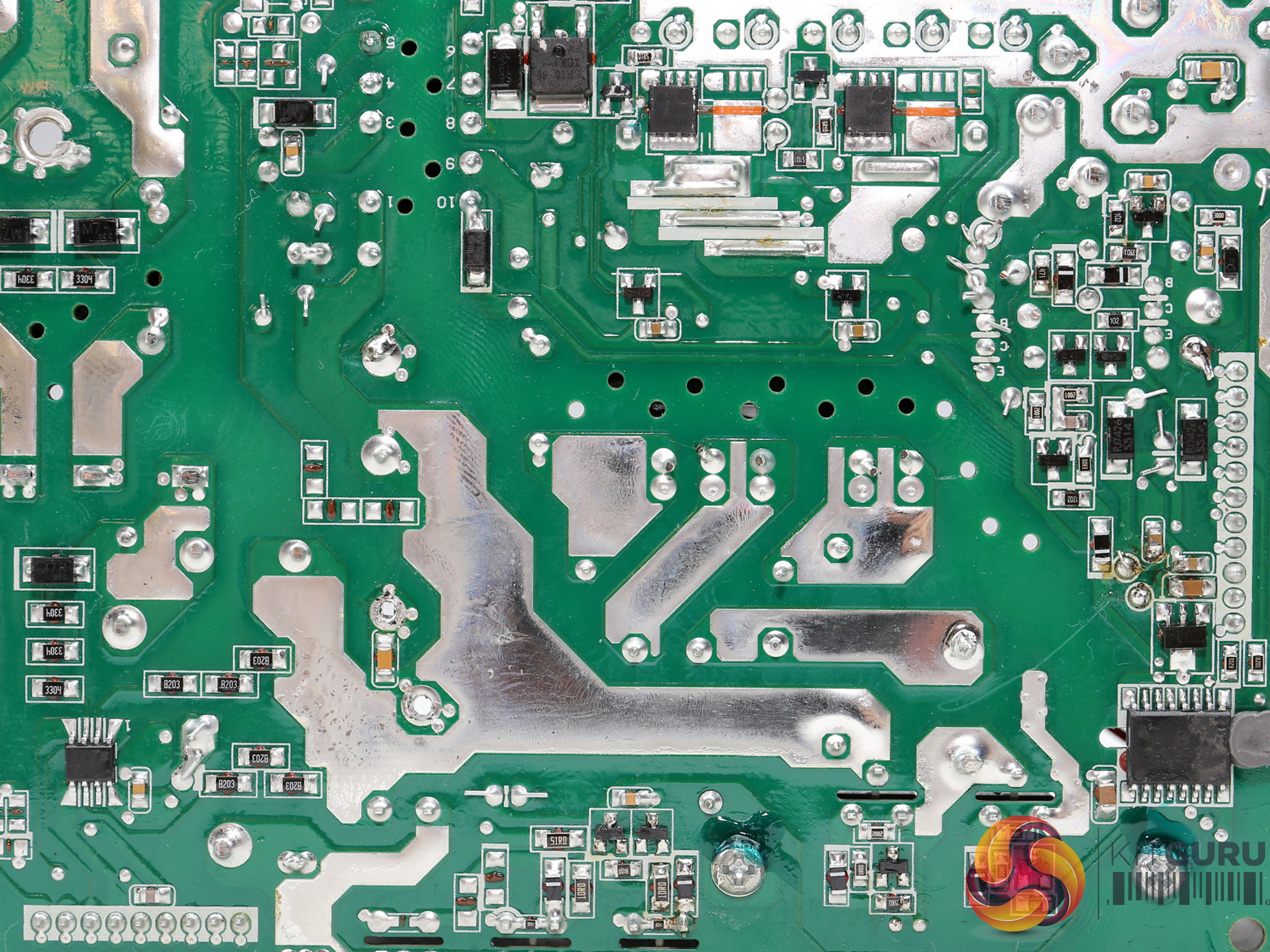
A couple of Toshiba TPHR85 04PL FETs regulate the +12V rail. They are installed on the solder side of the PCB, while two small heatsinks right above them assist in their cooling.
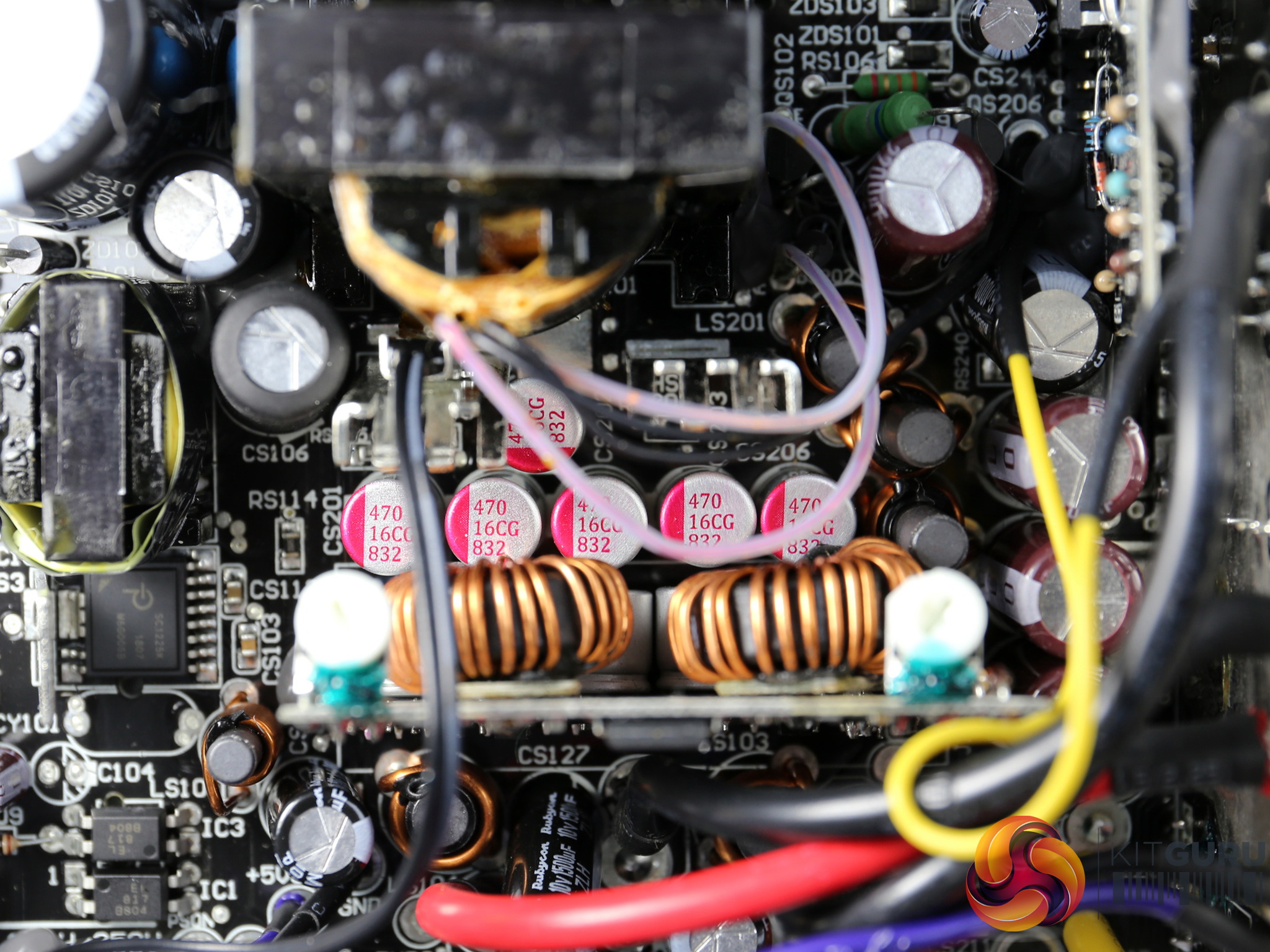
The electrolytic filtering caps in the secondary side are provided by Chemi-Con and Rubycon. We also find a number of Teapo polymer caps.
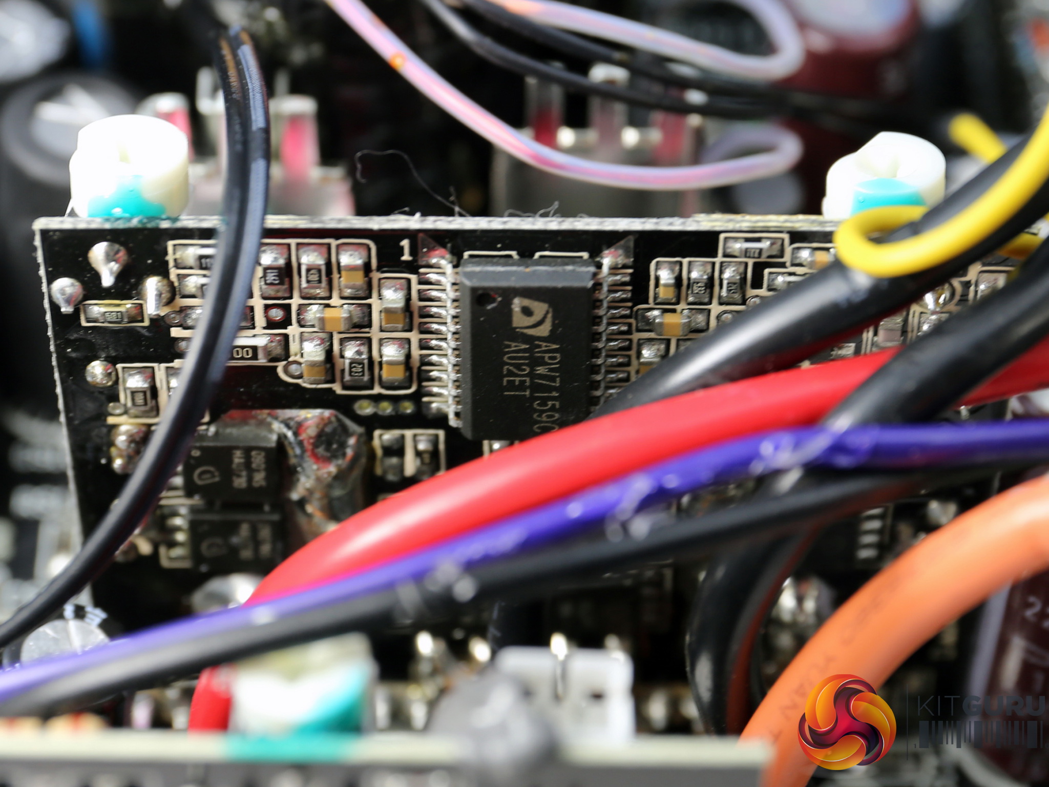
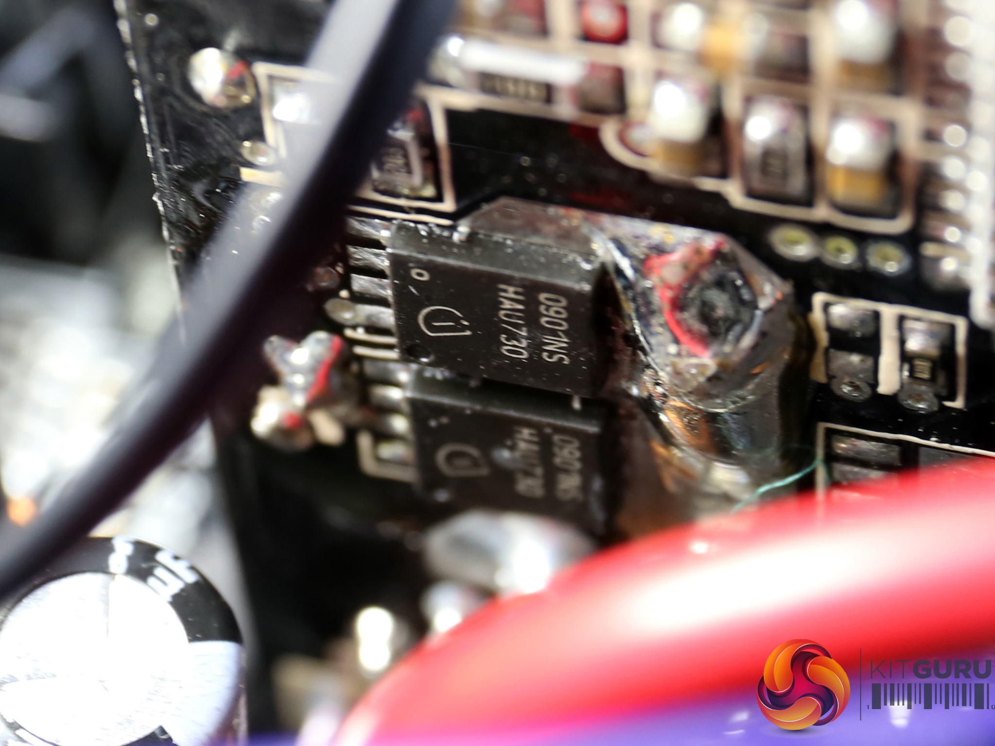
The voltage regulation modules that generate the minor rails use in total six Infineon BSC0901NS FETs, while the common PWM controller is an Anpec APW7159C.
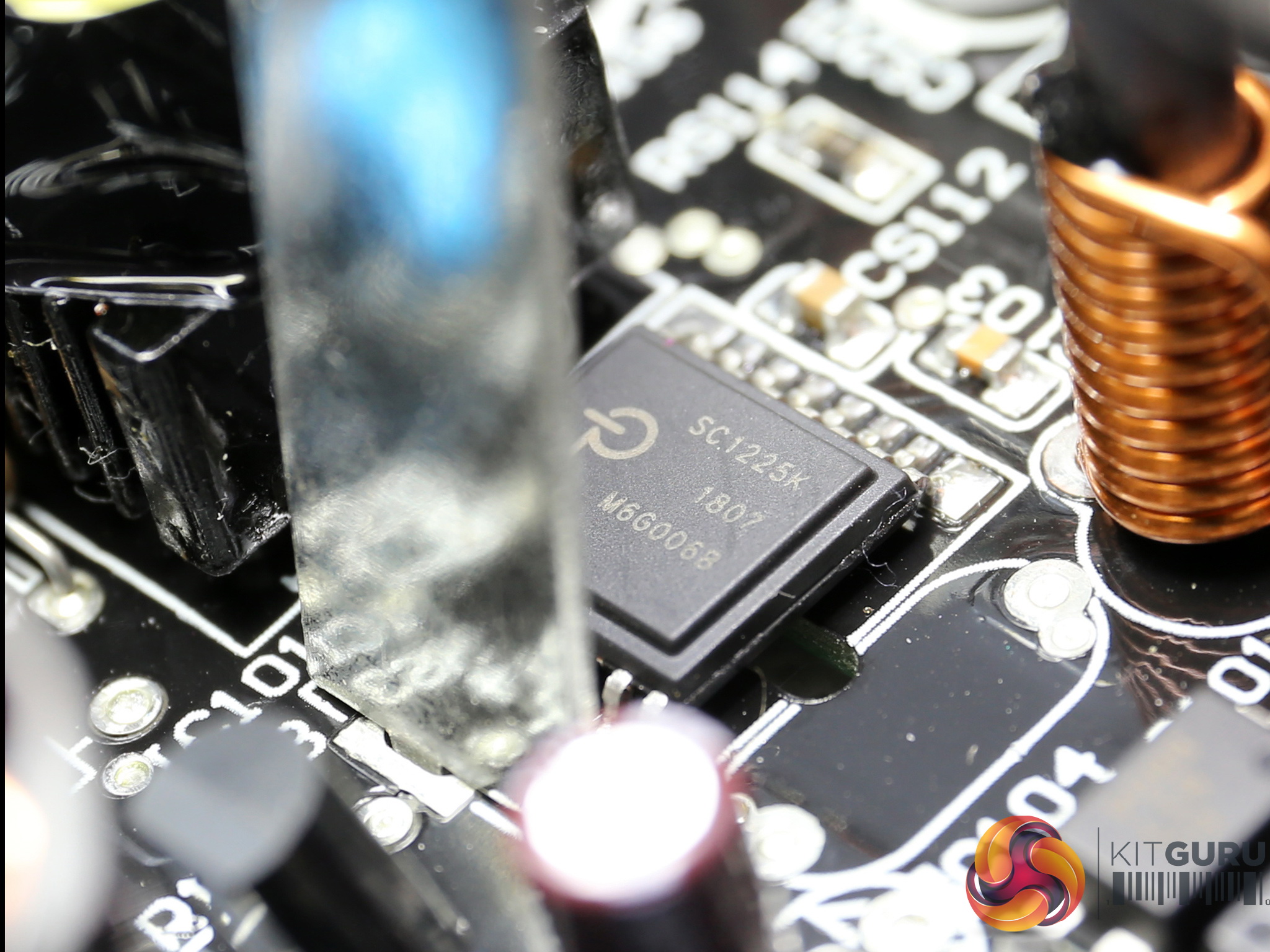
The controller of the highly efficient 5VSB circuit is a Power Integrations SC1225K IC. An International Rectifier IRFR1018E FET is also used.
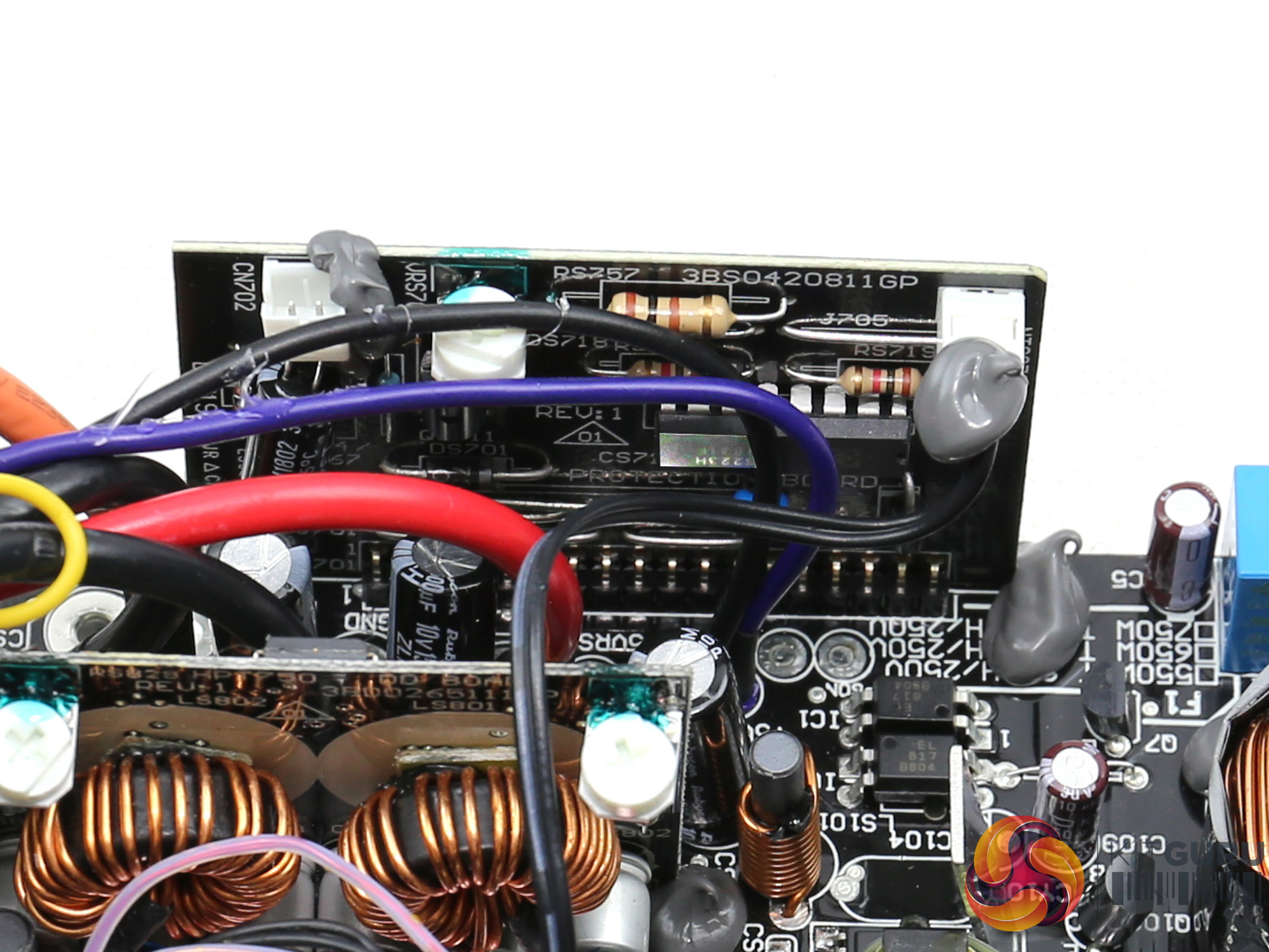
The supervisor IC is a SITI PS223, which is among the very few supporting over temperature protection out of the box.
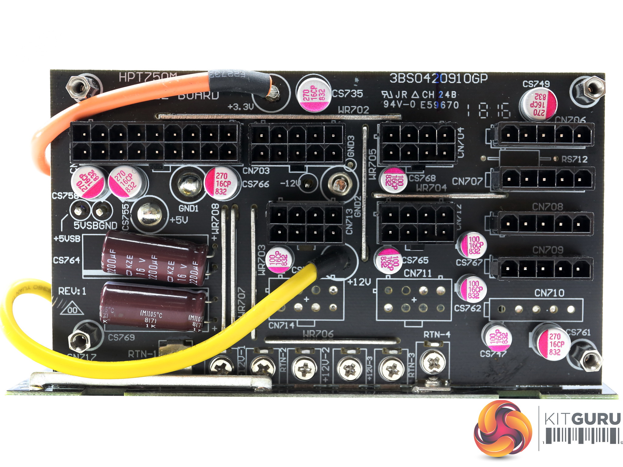
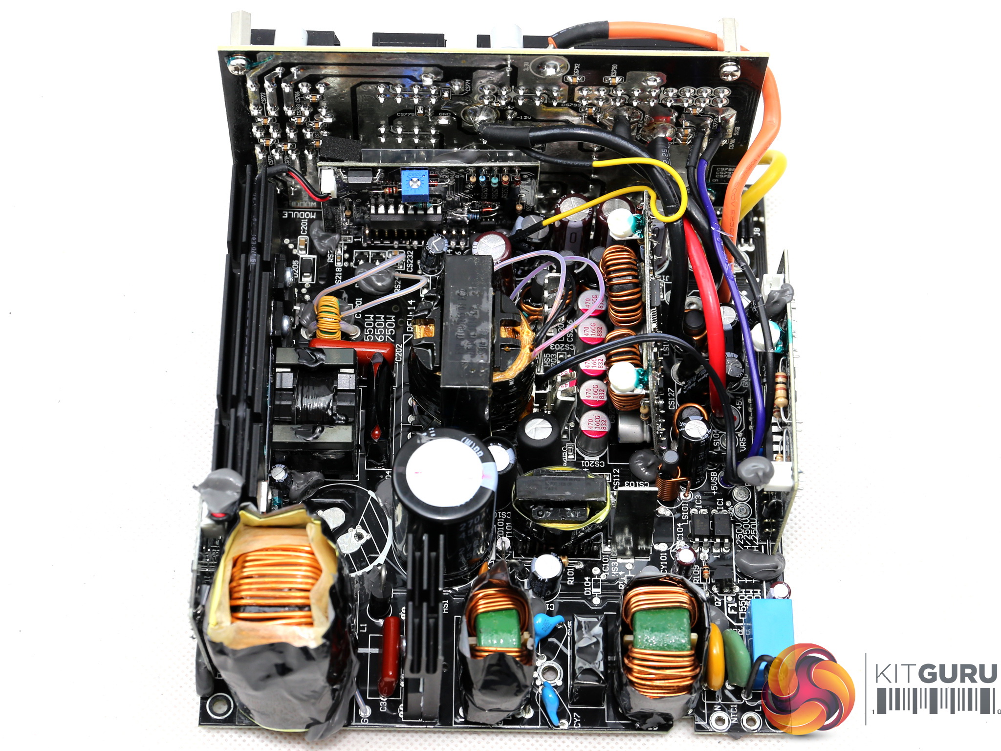
At the face of the modular board we meet a couple of KZE caps along with several Teapo polymers. Although this board is connected to the main one through bus bars, still FSP uses two thick wires to transfer a part of the +12V rail along with the 3.3V one. The use of power transfer wires is not a good practice though since it affects airflow and on top of that those cables, in the majority of cases cause higher voltage drops compared to other means of power transfer (e.g. thick PCB traces and bus bars).
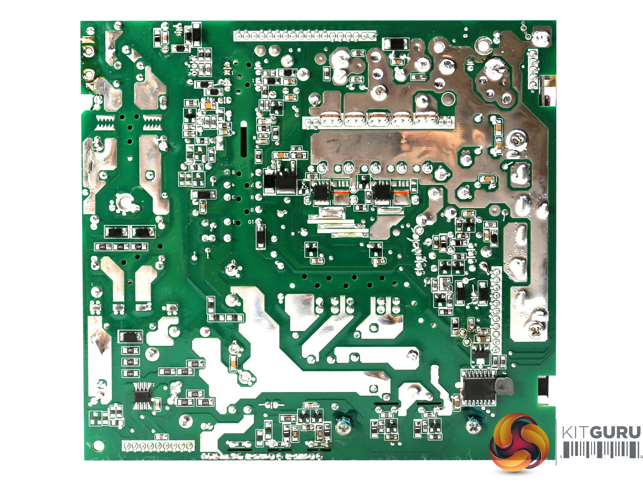
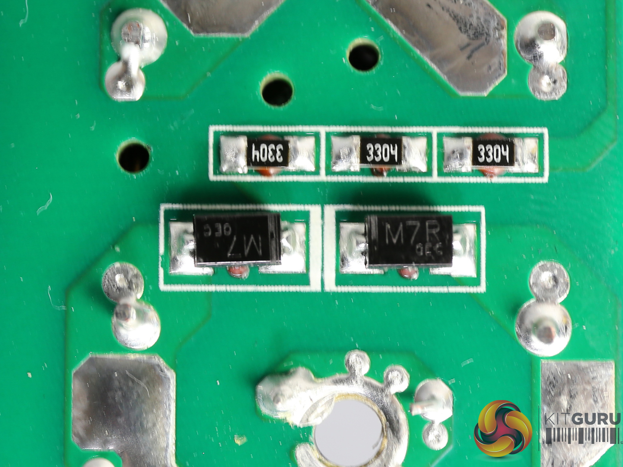
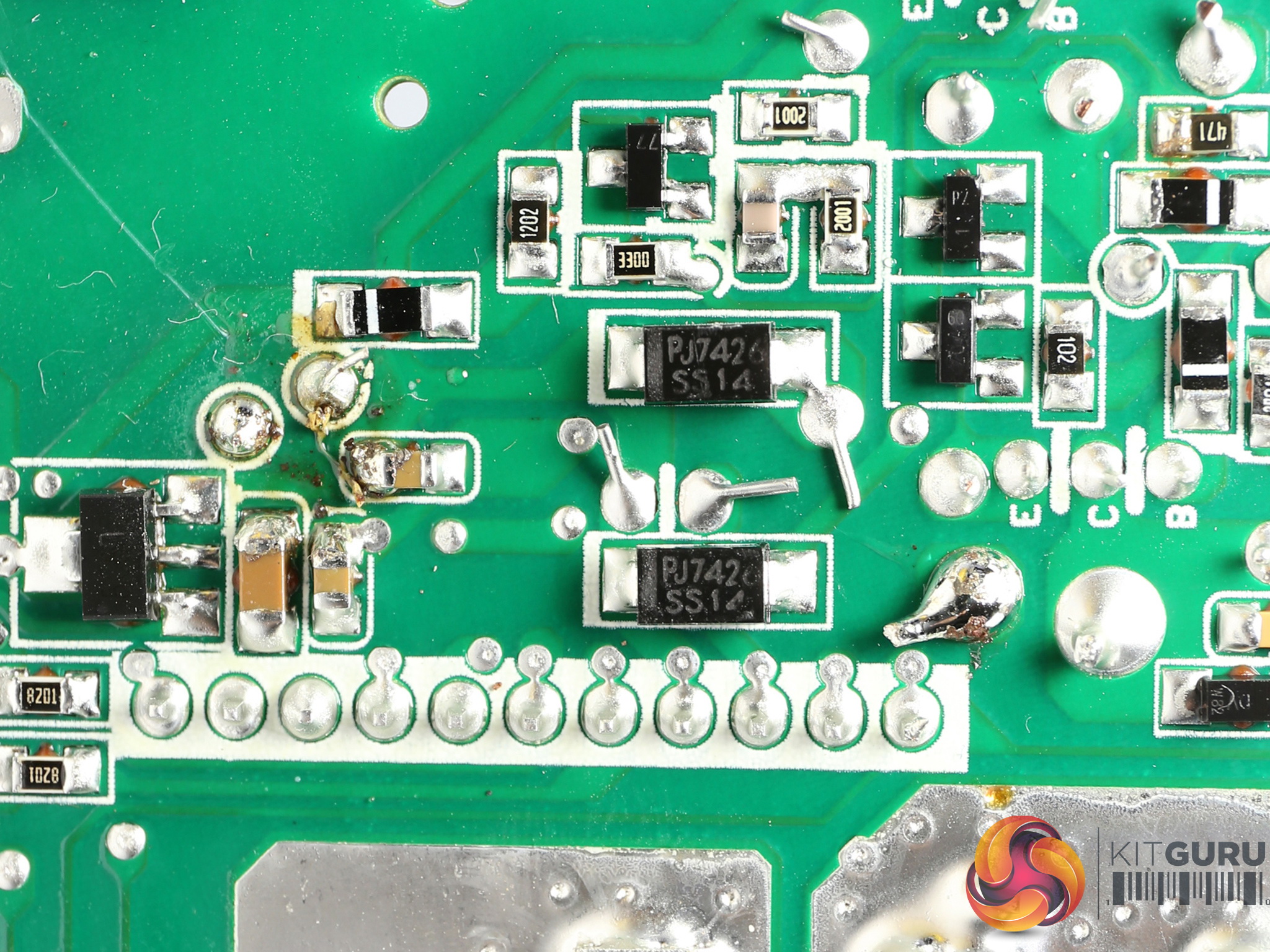
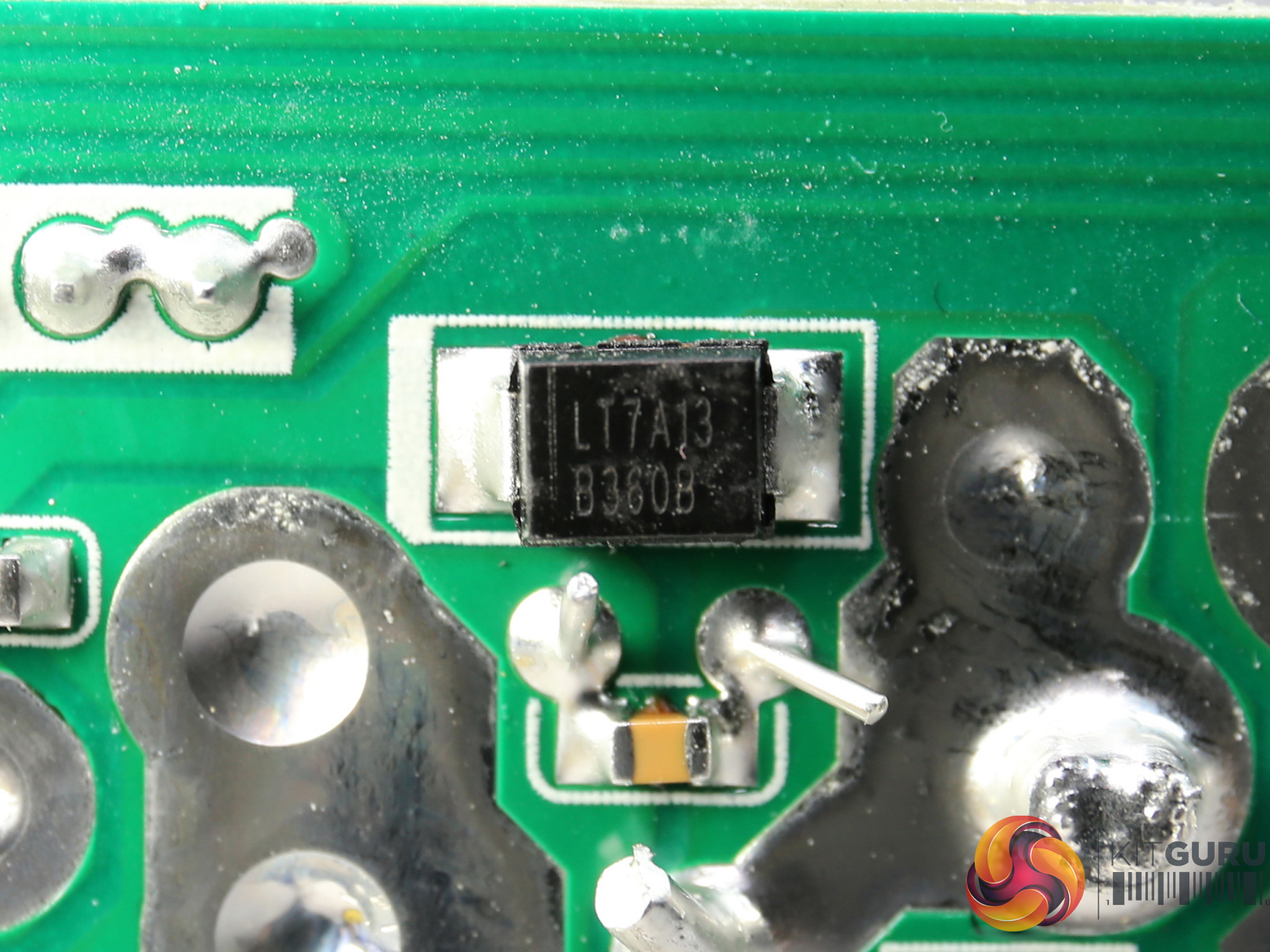
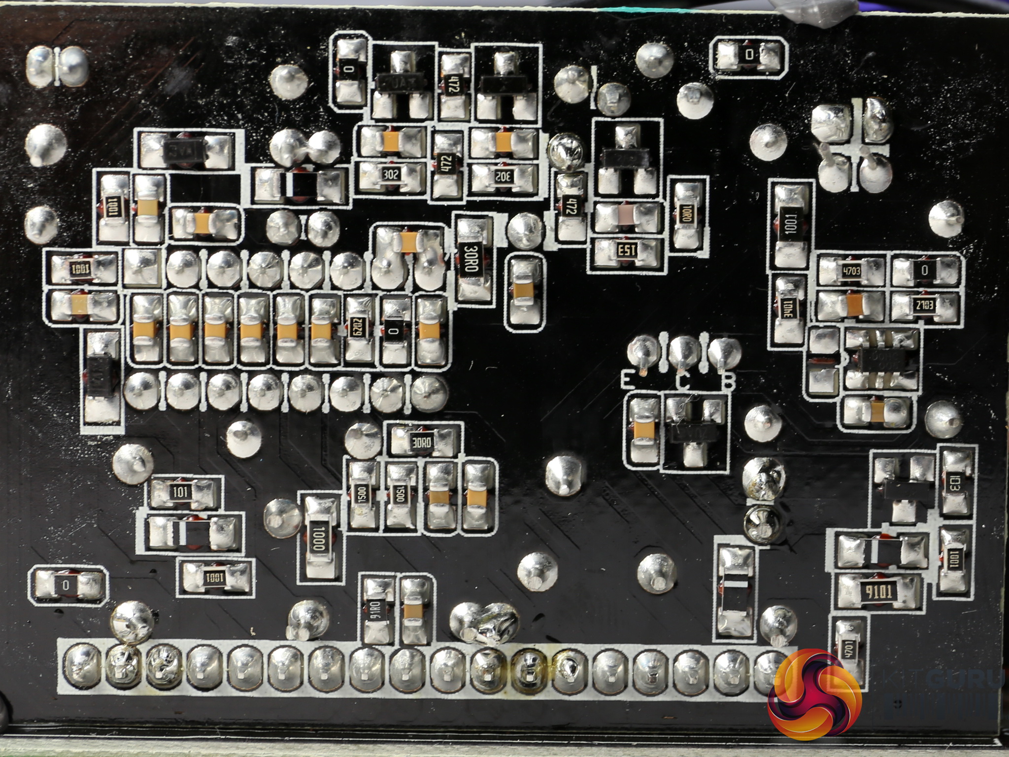
The soldering quality is not the best we have seen from FSP; in some areas we notice sloppy solders and to make matters worse, we also find some pretty long component leads, which we hate to see since they are a sign of inferior quality control.
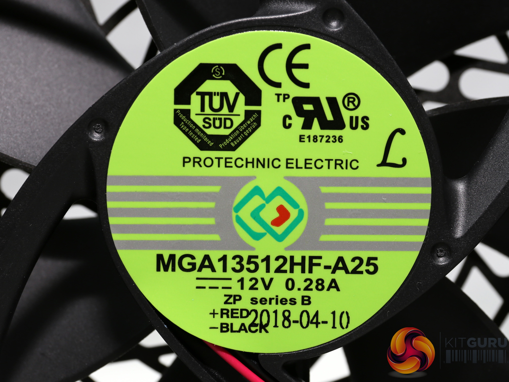
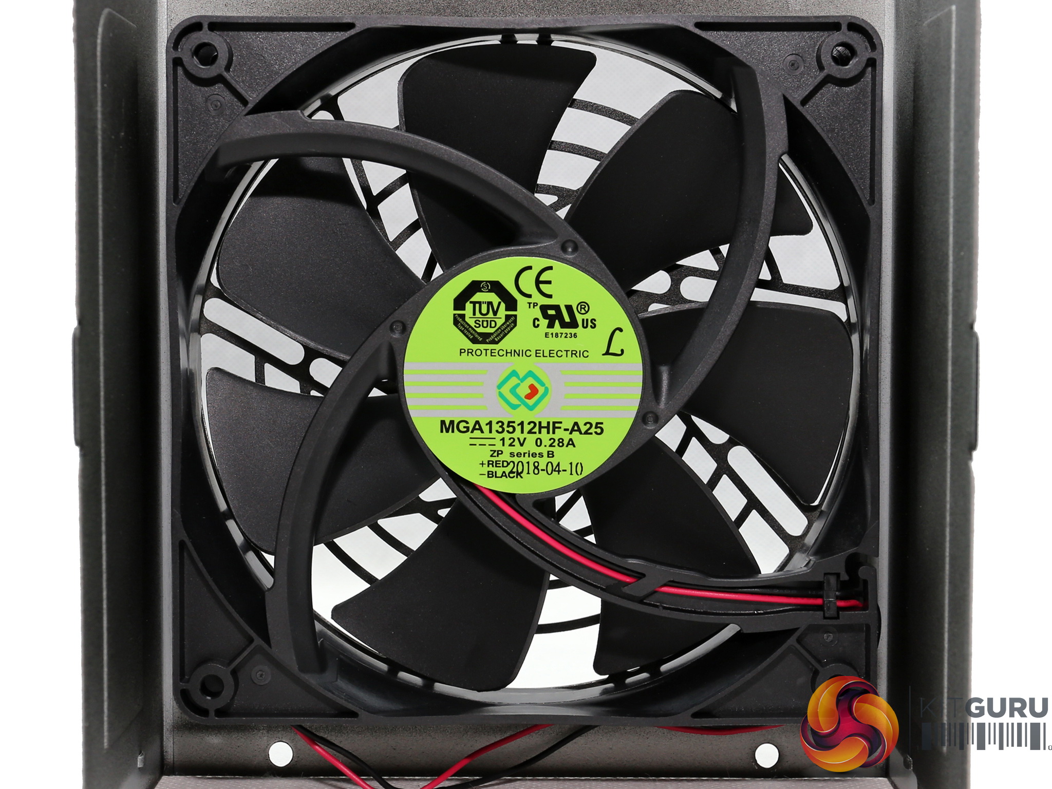
You can never go wrong with a Protechnic Electric fan, since they are of high quality. The fan's model number is MGA13512HF-A25 and it uses a fluid dynamic bearing which will last for long.
To learn more about our PSU tests and methodology, please check out How We Test Power Supply Units.
Primary Rails And 5VSB Load Regulation
Load Regulation testing is detailed here.
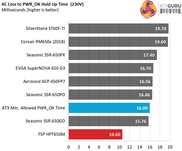
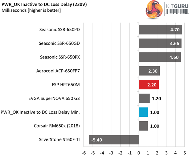
Hold-Up Time
Our hold-up time tests are described in detail here.
The oscilloscope screenshots that we took during the hold-up time measurements:
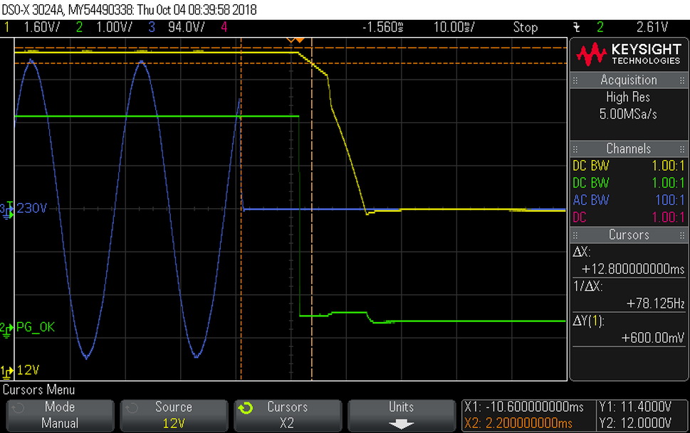
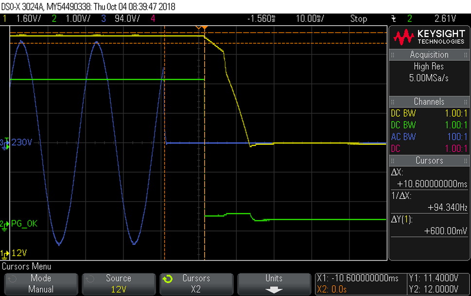
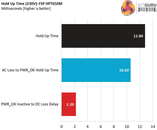
The hold-up time is low, which is a great shame for a high-end 650W unit.
Inrush Current
For details on our inrush current testing, please click here.
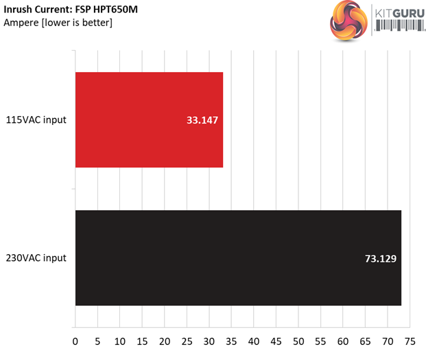
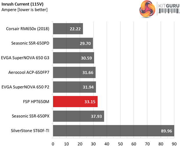
The inrush current with 115V is at normal levels, however it is quite high with 230V.
Load Regulation And Efficiency Measurements
The first set of tests reveals the stability of the voltage rails and the HPT650M’s efficiency. The applied load equals (approximately) 10 to 110 percent of the power supplies maximum load in increments of 10 percentage points.
We conducted two additional tests.
During the first, we stressed the two minor rails (5V and 3.3V) with a high load, while the load at +12V was only 0.1A. This test reveals whether a power supply is compatible with Intel’s C6/C7 sleep states or not. In the second test, we determined the maximum load the +12V rail could handle with minimal load on the minor rails.
| Test # | 12V | 5V | 3.3V | 5VSB | DC/AC (Watts) | Efficiency | Fan Speed (RPM) | PSU Noise (dB[A]) | Temps (In/Out) | PF/AC Volts |
| 1 | 3.579A | 1.969A | 1.959A | 0.995A | 64.846 | 86.095% | 705 | 17.0 | 40.08°C | 0.845 |
| 12.081V | 5.081V | 3.369V | 5.029V | 75.319 | 42.90°C | 115.05V | ||||
| 2 | 8.157A | 2.958A | 2.947A | 1.195A | 129.346 | 90.007% | 708 | 17.1 | 40.63°C | 0.943 |
| 12.069V | 5.071V | 3.359V | 5.021V | 143.707 | 44.04°C | 115.05V | ||||
| 3 | 13.138A | 3.458A | 3.429A | 1.398A | 194.430 | 91.319% | 710 | 17.1 | 41.29°C | 0.970 |
| 12.059V | 5.063V | 3.351V | 5.008V | 212.912 | 45.21°C | 115.05V | ||||
| 4 | 18.131A | 3.958A | 3.948A | 1.603A | 259.663 | 91.644% | 703 | 17.0 | 41.82°C | 0.981 |
| 12.049V | 5.054V | 3.342V | 4.994V | 283.338 | 46.13°C | 115.05V | ||||
| 5 | 22.798A | 4.957A | 4.950A | 1.808A | 324.951 | 91.485% | 700 | 16.9 | 42.21°C | 0.986 |
| 12.038V | 5.045V | 3.333V | 4.979V | 355.195 | 47.14°C | 115.05V | ||||
| 6 | 27.409A | 5.959A | 5.959A | 2.016A | 389.482 | 91.091% | 697 | 16.9 | 42.81°C | 0.989 |
| 12.028V | 5.035V | 3.323V | 4.961V | 427.576 | 48.24°C | 115.05V | ||||
| 7 | 32.092A | 6.966A | 6.973A | 2.225A | 454.792 | 90.320% | 945 | 26.2 | 43.07°C | 0.990 |
| 12.018V | 5.025V | 3.313V | 4.946V | 503.532 | 48.80°C | 115.04V | ||||
| 8 | 36.785A | 7.977A | 7.994A | 2.435A | 520.098 | 89.657% | 1115 | 30.8 | 43.46°C | 0.991 |
| 12.007V | 5.016V | 3.303V | 4.930V | 580.099 | 49.54°C | 115.04V | ||||
| 9 | 41.880A | 8.491A | 8.497A | 2.438A | 584.991 | 88.985% | 1255 | 34.1 | 44.34°C | 0.991 |
| 11.998V | 5.007V | 3.295V | 4.923V | 657.406 | 50.91°C | 115.04V | ||||
| 10 | 46.920A | 9.004A | 9.037A | 2.546A | 649.690 | 88.243% | 1425 | 35.0 | 45.54°C | 0.991 |
| 11.988V | 4.999V | 3.286V | 4.912V | 736.247 | 52.40°C | 115.04V | ||||
| 11 | 52.381A | 9.019A | 9.062A | 2.550A | 714.536 | 87.343% | 1617 | 40.6 | 46.62°C | 0.991 |
| 11.976V | 4.991V | 3.278V | 4.903V | 818.077 | 53.82°C | 115.03V | ||||
| CL1 | 0.138A | 14.002A | 13.999A | 0.000A | 119.144 | 86.459% | 715 | 17.2 | 42.21°C | 0.942 |
| 12.052V | 5.049V | 3.342V | 5.042V | 137.804 | 47.18°C | 115.05V | ||||
| CL2 | 54.171A | 1.002A | 1.000A | 1.000A | 663.351 | 88.522% | 1380 | 37.0 | 45.86°C | 0.991 |
| 12.000V | 5.016V | 3.301V | 4.971V | 749.365 | 52.72°C | 115.03V |
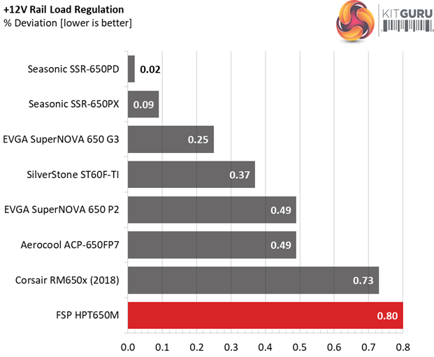
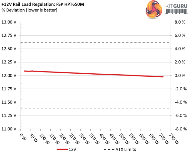
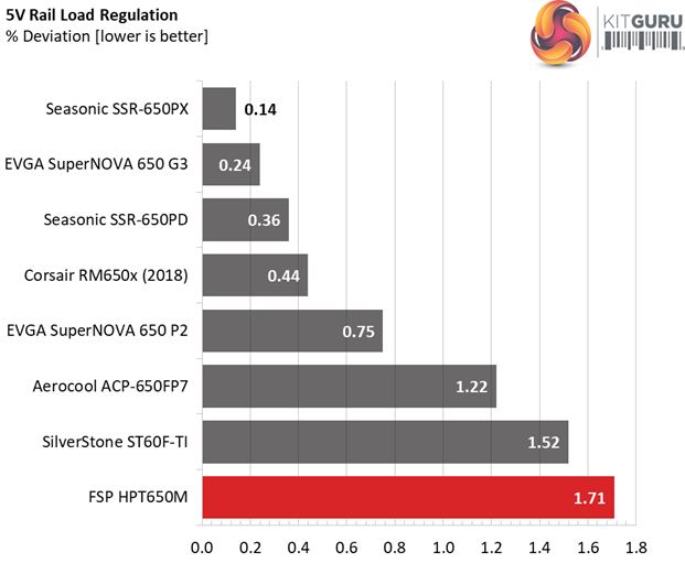
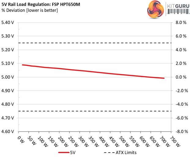
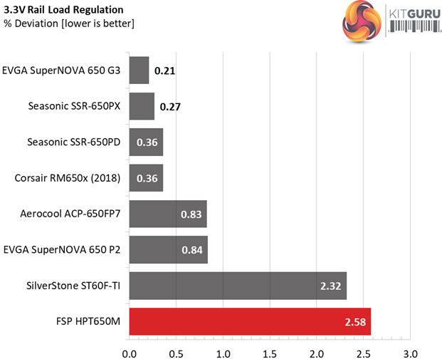
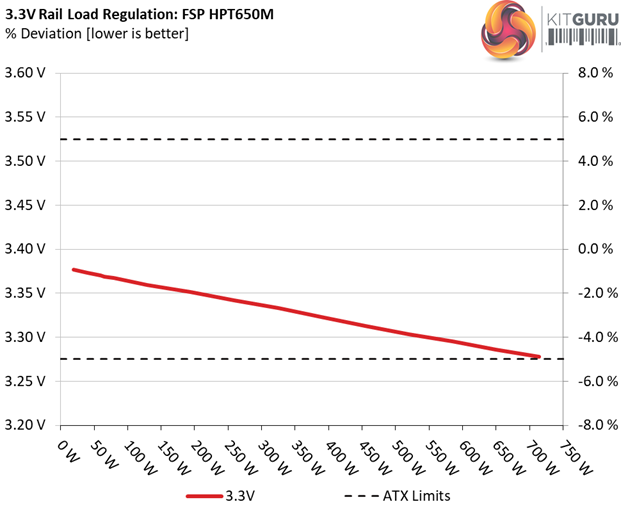
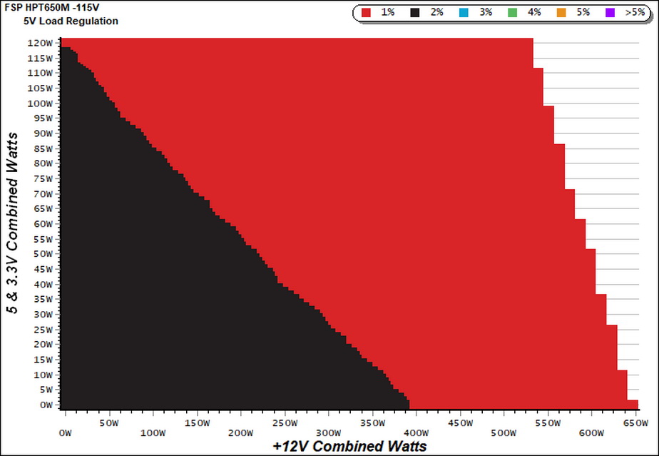
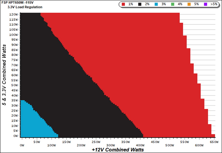
The load regulation at +12V is satisfactory and the 5V rail stays within 2%. The regulation at 3.3V could be much better though, since the competition is way ahead here. This rail might not be so important nowadays, but from the moment it is included in the ATX spec and some components still use it, it should have the best possible performance.
The fan profile is super relaxed. It takes more than full load to force the fan spin at 1617 RPM, where the noise output slightly exceeds 40 dB(A). This means that under normal operating temperatures you will barely hear the PSU's fan.
With 20% load the corresponding 80 PLUS Platinum requirement is met, however this is not the case with 50% and 100% loads. Nevertheless, we test at a much higher ambient so it is normal to get lower efficiency readings.
Efficiency
Our efficiency testing procedure is detailed here.
Using results from the previous page, we plotted a chart showing the HPT650M’s efficiency at low loads, and loads from 10 to 110 percent of its maximum-rated capacity.
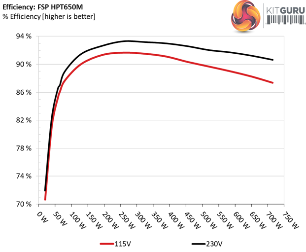
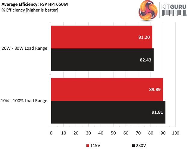
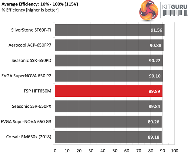
The efficiency with normal loads is high, following closely the Leadex and Prime Platinum platforms. Under light loads FSP's offer has decent performance, however it has a hard time catching up with the competition. Even the 80 PLUS Gold rated, EVGA 650 G3 is ahead of it.
Efficiency At Low Loads
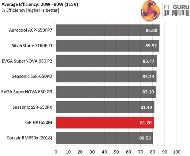
In the following tests, we measure the HPT650M's efficiency at loads significantly lower than 10 percent of its maximum capacity (the lowest load the 80 PLUS standard measures). The loads we dial are 20, 40, 60, and 80W. This is important for representing when a PC is idle, with power-saving features turned on.
| Test # | 12V | 5V | 3.3V | 5VSB | DC/AC (Watts) | Efficiency | Fan Speed (RPM) | PSU Noise (dB[A]) | PF/AC Volts |
| 1 | 1.194A | 0.492A | 0.472A | 0.197A | 19.524 | 70.642% | 708 | 17.1 | 0.697 |
| 12.083V | 5.089V | 3.377V | 5.068V | 27.638 | 115.05V | ||||
| 2 | 2.454A | 0.983A | 0.976A | 0.396A | 39.938 | 81.132% | 708 | 17.1 | 0.773 |
| 12.080V | 5.086V | 3.373V | 5.058V | 49.226 | 115.05V | ||||
| 3 | 3.644A | 1.476A | 1.452A | 5.042A | 59.431 | 85.371% | 708 | 17.1 | 0.831 |
| 12.085V | 5.082V | 3.370V | 5.042V | 69.615 | 115.05V | ||||
| 4 | 4.904A | 1.969A | 1.958A | 0.795A | 79.842 | 87.666% | 705 | 17.0 | 0.882 |
| 12.081V | 5.079V | 3.367V | 5.035V | 91.075 | 115.05V |
We would like to see higher efficiency in the first test. In the rest tests the unit passes the 80% mark. During the entire light load testing procedure the fan spins at a very low speed, producing equally low noise, which most likely most users won't even notice.
5VSB Efficiency
The ATX specification (revision 1.4), along with CEC, ErP Lot 3 2014 and ErP Lot 6 2010/2013, states that the 5VSB standby supply efficiency should be as high as possible, recommending 75 percent or higher with 550mA, 1A, and 1.5A of load.
The supply should also achieve higher than 75% efficiency at 5VSB under full load, or with 3A if its max current output on this rail is higher than 3A.
We take six measurements: one each at 100, 250, 550, 1000, and 1500mA, and one with the full load the 5VSB rail can handle.
| Test # | 5VSB | DC/AC (Watts) |
Efficiency | PF/AC Volts |
| 1 | 0.100A | 0.508 | 79.749% | 0.052 |
| 5.079V | 0.637 | 115.06V | ||
| 2 | 0.250A | 1.269 | 83.377% | 0.207 |
| 5.075V | 1.522 | 115.06V | ||
| 3 | 0.550A | 2.782 | 84.559% | 0.321 |
| 5.058V | 3.290 | 115.06V | ||
| 4 | 1.000A | 5.045 | 85.162% | 0.393 |
| 5.044V | 5.924 | 115.06V | ||
| 5 | 1.500A | 7.548 | 84.213% | 0.434 |
| 5.031V | 8.963 | 115.06V | ||
| 6 | 2.500A | 12.482 | 83.598% | 0.473 |
| 4.993V | 14.931 | 115.06V |
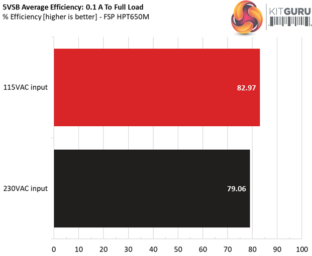
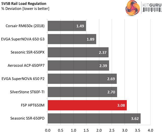
FSP is known for its highly efficient 5VSB circuits. The moment other manufacturers don't care so much about this rail, FSP's engineers strive to provide the best possible 5VSB efficiency and the results are just great! This unit has one of the most efficient 5VSB rail's that we have ever encountered.
Power Consumption In Idle And Standby
In the table below, you’ll find the power consumption and voltage values of all rails (except -12V) when the PSU is idle (powered on, but without any load on its rails), and the power consumption when the unit is in standby mode (without any load, at 5VSB).
| Mode | 12V | 5V | 3.3V | 5VSB | Watts | PF/AC Volts |
| Idle | 12.170V | 5.091V | 3.377V | 5.081V | 7.376 | 0.505 |
| 115.1V | ||||||
| Standby | 0.048 | 0.052 | ||||
| 115.1V | ||||||
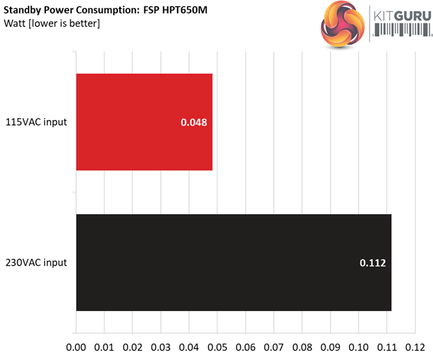
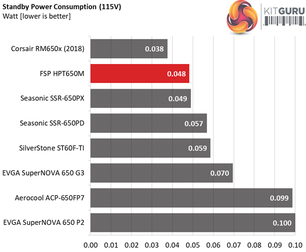
The vampire power levels with 115V are very low, however this is not the case with 230V where the power consumption at standby is a little above the average.
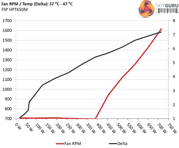
Fan RPM, Delta Temperature, And Output Noise
Our mixed noise testing is described in detail here.
The first chart below illustrates the cooling fan's speed (in RPM), and the delta between input and output temperature. The results were obtained at 37°C (98.6°F) to 47°C (116.6°F) ambient temperature.
The next chart shows the cooling fan's speed (again, in RPM) and output noise. We measure acoustics from one meter away, inside a hemi-anechoic chamber. Background noise inside the chamber is below 6 dB(A) during testing (it's actually much lower, but our sound meter microphone hits its floor), and the results are obtained with the PSU operating at 37°C (98.6°F) to 47°C (116.6°F)
ambient temperature.
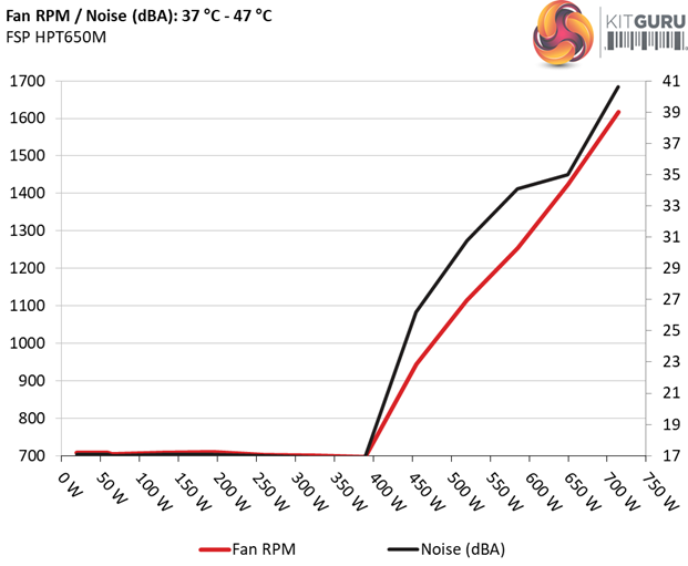
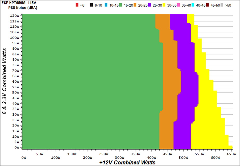
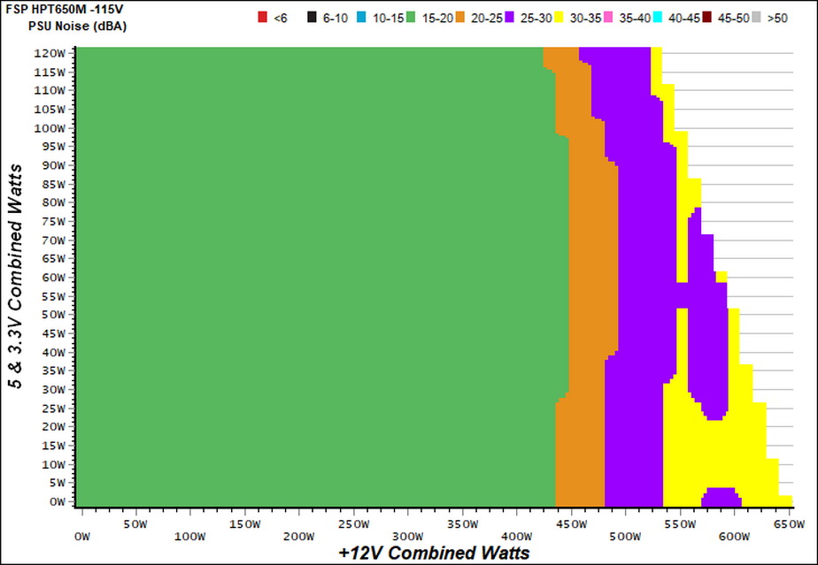
The following graph illustrates the fan's output noise over the PSU's operating range. The same conditions of the above graph apply to our measurements, though the ambient temperature is between 30°C (86°F) to 32°C (89.6°F).
As we already stated, the fan profile is super relaxed. With a so low minimum fan speed there is no need for a semi-passive operation.
The unit enters the 30-35 dB(A) zone only once the load goes higher than 530W, while the ambient is between 30-32°C.
Protection Features
Our protection features evaluation methodology is described in detail here.
|
Protection |
|
|
OCP |
12V: 64.8A (119.62%), 11.999V |
|
OPP |
788.3W (121.28%) |
|
OTP |
✓ (140°C @ 12V Heatsink) |
|
SCP |
12V: ✓ |
|
PWR_OK |
Accurate (but lower than 16ms) |
|
NLO |
✓ |
|
SIP |
Surge: MOV |
The OCP triggering points at +12V and 5V are reasonably set, while at 3.3V and 5VSB are higher than the normal, which usually is around 130%. The over power protection is configured properly and the over temperature protection works well.
As expected, there is short circuit protection on all rails and the power ok signal is accurate, however it is much lower than 16ms. Finally, there is an MOV for surge protection and the large inrush currents are suppressed by a NTC thermistor, which is supported by a bypass relay.
DC Power Sequencing
According to Intel’s most recent Power Supply Design Guide (revision 1.4) the +12V and 5V voltages must be equal or greater than the 3.3V rail’s output at all times, during the power-up and normal operation. For our first measurement, we turn the unit off and switch it back on without any load in any of the rails.
In the second test, we set the PSU to standby mode, dial full load and start it afterwards. In the last test, while the power supply is completely switched off (we cut off the power or switch the supply off through its power switch), we dial full load before restoring power.
In all cases the 3.3V rail's voltage is lower than +12V and 5V, as the ATX spec requires.
Our cross-load tests are described in detail here.
To generate the following charts, we set our loaders to auto mode through our custom-made software before trying more than 1500 possible load combinations with the +12V, 5V, and 3.3V rails. The load regulation deviations in each of the charts below are calculated by taking the nominal values of the rails (12V, 5V, and 3.3V) as point zero. The ambient temperature is between at 30°C (86°F) to 32°C (89.6°F).
Load Regulation Charts

Efficiency Chart
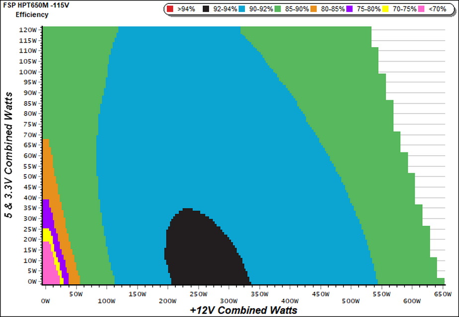
It is good to see a region where efficiency is higher than 92%. From around 110W to 540W at +12V and even with very high loads on the minor rails, the PSU's efficiency stays above 90%.
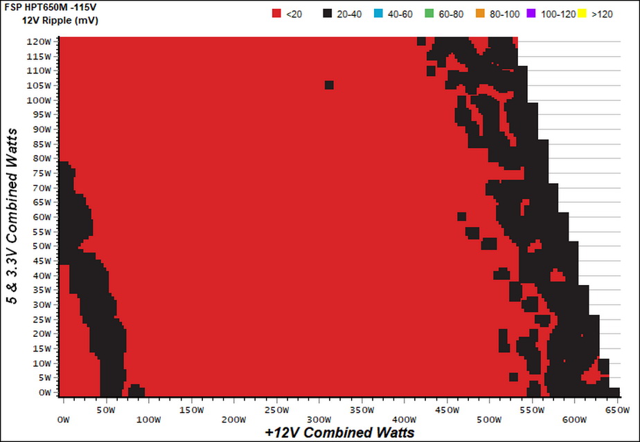
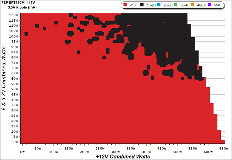
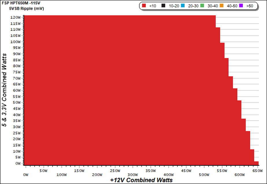
Ripple Charts

Infrared Images
We apply half-load for 10 minutes with the PSU’s top cover and cooling fan removed before taking photos with our modified FLIR E4 camera that delivers 320×240 IR resolution (76,800 pixels).
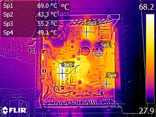
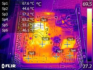
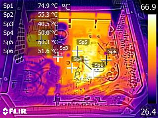
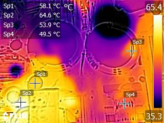
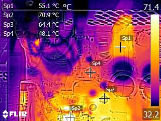
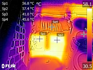
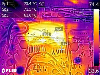
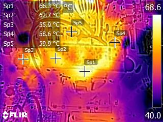
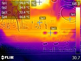
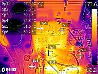
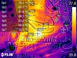
The temperatures at the internals stay low. This is why FSP opted for a very relaxed fan profile.
Advanced Transient Response Tests
For details on our transient response testing, please click here.
These tests are crucial because they simulate the transient loads a PSU is likely to handle (such as booting a RAID array or an instant 100 percent load of CPU/GPUs). We call these “Advanced Transient Response Tests” and they are designed to be very tough to master, especially for a PSU with a capacity of less than 500W.
In all of the tests, we use an oscilloscope to measure the voltage drops caused by the transient load. The voltages should remain within the ATX specification regulation limits.
We should note that the ATX spec requires for capacitive loading during the transient rests, but in our methodology we chose to apply the worst case scenario with no extra capacitance on the rails.
Advanced Transient Response at 20 Percent – 200ms
| Voltage | Before | After | Change | Pass/Fail |
|---|---|---|---|---|
| 12V | 12.073V | 11.935V | 1.14% | Pass |
| 5V | 5.071V | 4.933V | 2.72% | Pass |
| 3.3V | 3.358V | 3.170V | 5.60% | Pass |
| 5VSB | 5.022V | 4.969V | 1.06% | Pass |
Advanced Transient Response at 20 Percent – 20ms
| Voltage | Before | After | Change | Pass/Fail |
|---|---|---|---|---|
| 12V | 12.079V | 11.899V | 1.49% | Pass |
| 5V | 5.071V | 4.914V | 3.10% | Pass |
| 3.3V | 3.358V | 3.151V | 6.16% | Pass |
| 5VSB | 5.024V | 4.976V | 0.96% | Pass |
Advanced Transient Response at 20 Percent – 1ms
| Voltage | Before | After | Change | Pass/Fail |
|---|---|---|---|---|
| 12V | 12.080V | 11.934V | 1.21% | Pass |
| 5V | 5.071V | 4.934V | 2.70% | Pass |
| 3.3V | 3.358V | 3.150V | 6.19% | Pass |
| 5VSB | 5.025V | 4.988V | 0.74% | Pass |
Advanced Transient Response at 50 Percent – 200ms
| Voltage | Before | After | Change | Pass/Fail |
|---|---|---|---|---|
| 12V | 12.046V | 11.934V | 0.93% | Pass |
| 5V | 5.044V | 4.896V | 2.93% | Pass |
| 3.3V | 3.331V | 3.137V | 5.82% | Fail |
| 5VSB | 4.982V | 4.930V | 1.04% | Pass |
Advanced Transient Response at 50 Percent – 20ms
| Voltage | Before | After | Change | Pass/Fail |
|---|---|---|---|---|
| 12V | 12.053V | 11.899V | 1.28% | Pass |
| 5V | 5.045V | 4.898V | 2.91% | Pass |
| 3.3V | 3.331V | 3.115V | 6.48% | Fail |
| 5VSB | 4.986V | 4.937V | 0.98% | Pass |
Advanced Transient Response at 50 Percent – 1ms
| Voltage | Before | After | Change | Pass/Fail |
|---|---|---|---|---|
| 12V | 12.053V | 11.913V | 1.16% | Pass |
| 5V | 5.045V | 4.898V | 2.91% | Pass |
| 3.3V | 3.331V | 3.096V | 7.05% | Fail |
| 5VSB | 4.985V | 4.949V | 0.72% | Pass |
The transient response is mediocre at +12V and 5V and bad at 3.3V where the deviations are among the highest in the 650W category. FSP should look into this the sooner the possible.
Here are the oscilloscope screenshots we took during Advanced Transient Response Testing:
Transient Response At 20 Percent Load – 200ms
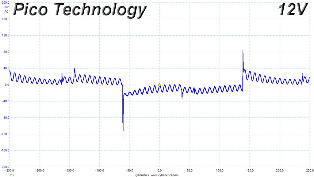
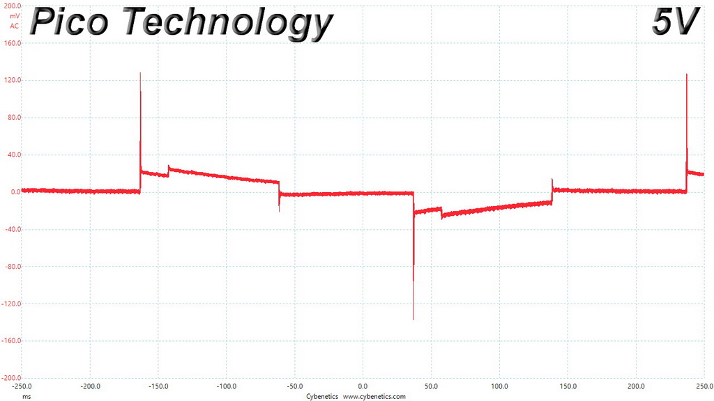
Transient Response At 20 Percent Load – 20ms
Transient Response At 20 Percent Load – 1ms
Transient Response At 50 Percent Load – 200ms
Transient Response At 50 Percent Load – 20ms
Transient Response At 50 Percent Load – 1ms
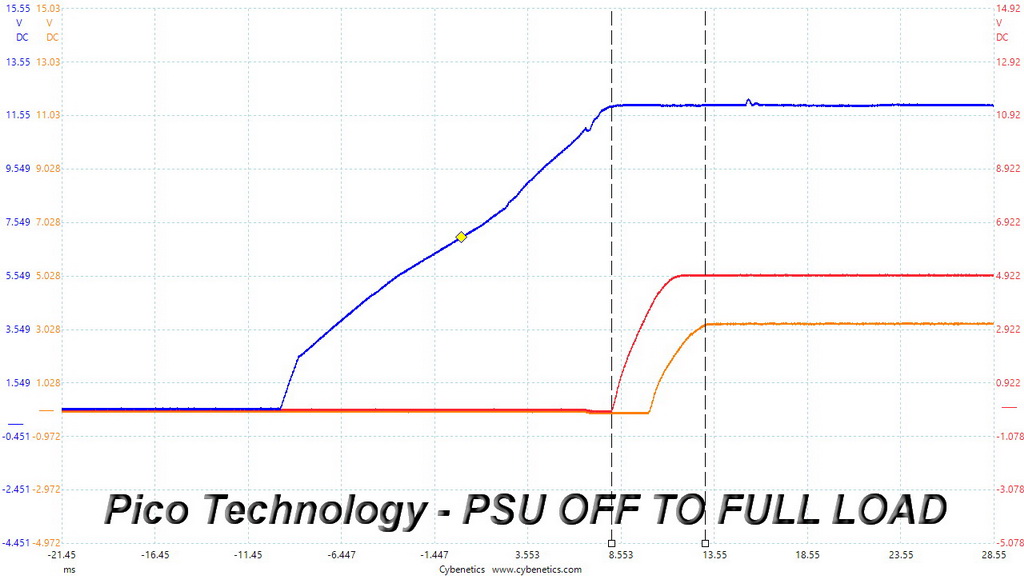
Turn-On Transient Tests
In the next set of tests, we measure the HPT650M’s response in simpler transient load scenarios—during its power-on phase.
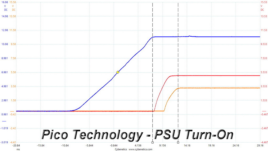
For our first measurement, we turn the PSU off, dial in the maximum current the 5VSB rail can handle, and switch the PSU back on.
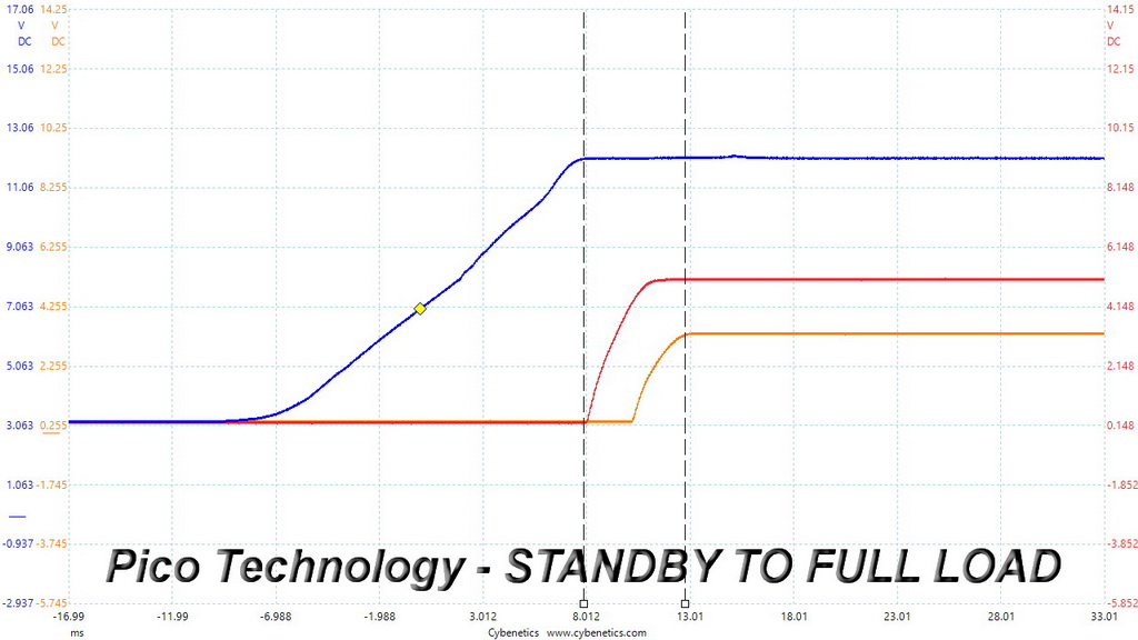
In the second test, we dial the maximum load the +12V rail can handle and start the PSU while it is in standby mode. In the last test, while the PSU is completely switched off (we cut off the power or switch the PSU off through its power switch), we dial the maximum load the +12V rail can handle before restoring power. The ATX specification states that recorded spikes on all rails should not exceed 10 percent of their nominal values (+10 percent for 12V is 13.2V, and 5.5 V for 5V).
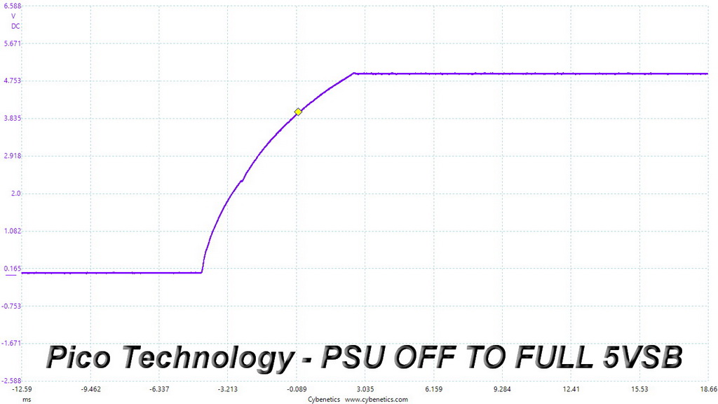
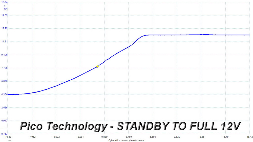
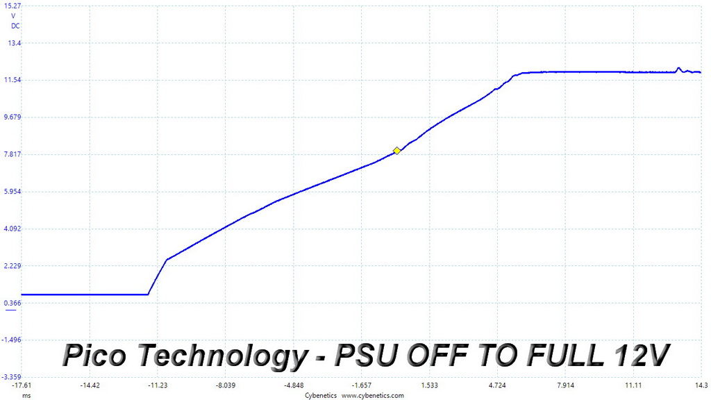
Fantastic results here! No spikes or voltage overshoots and all slopes ramp up smoothly.
To learn how we measure ripple, please click here.
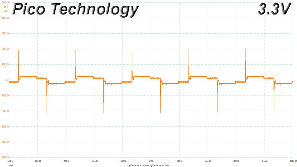
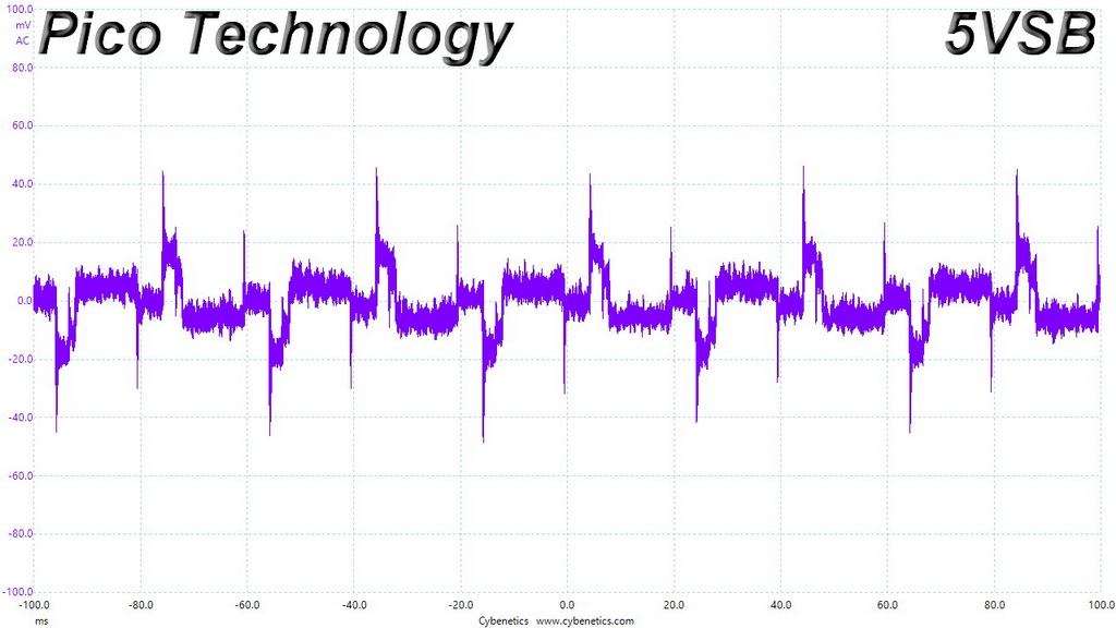
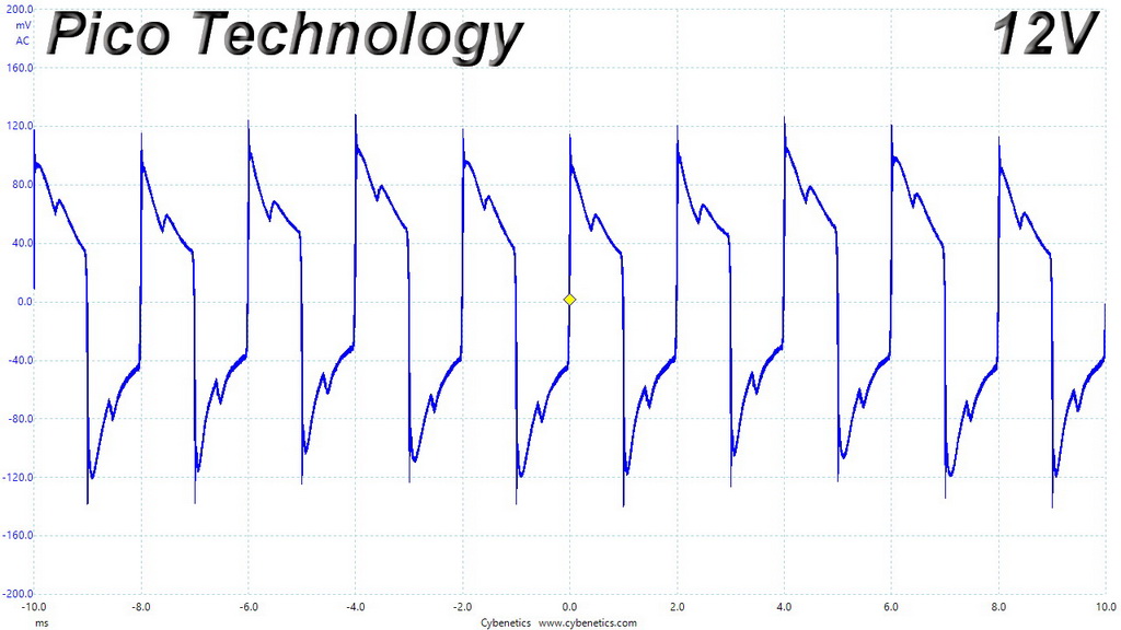
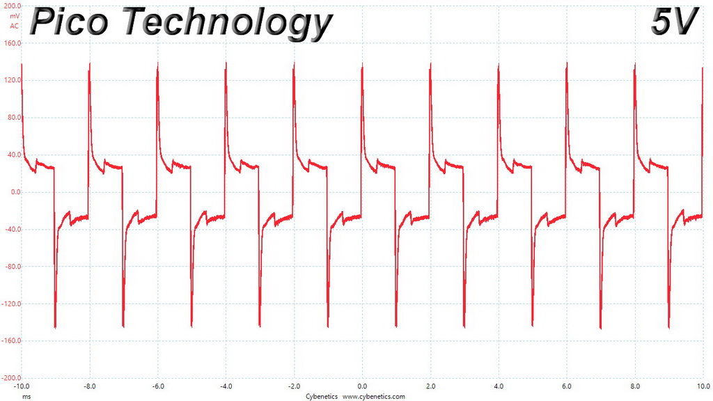
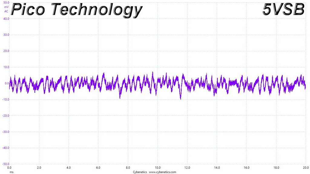
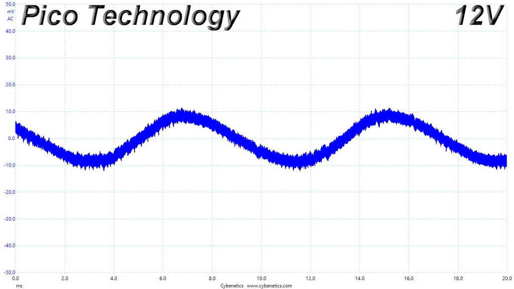
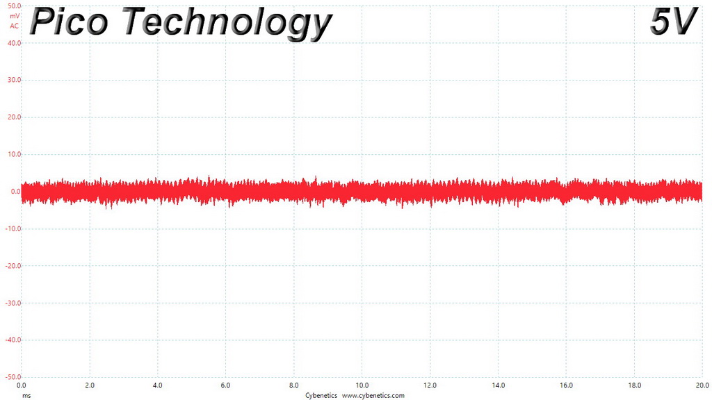
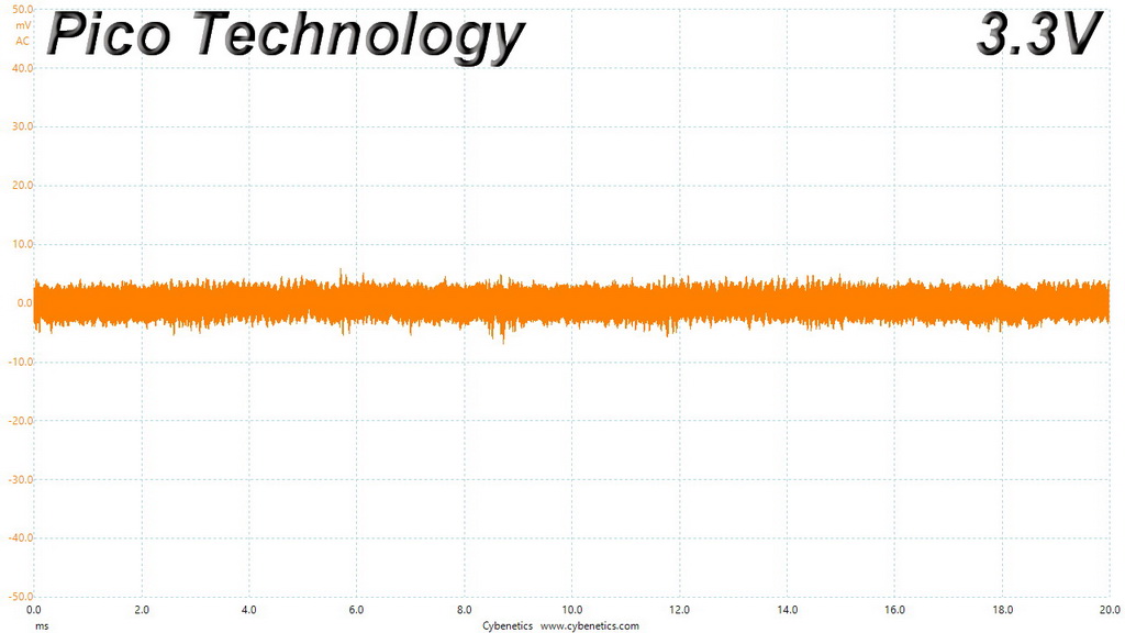
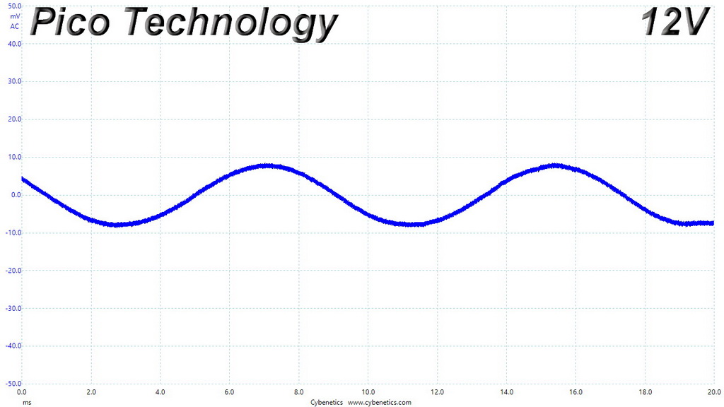
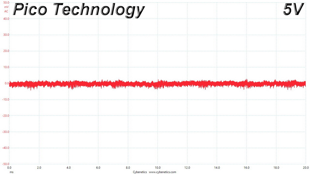
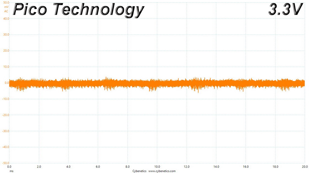
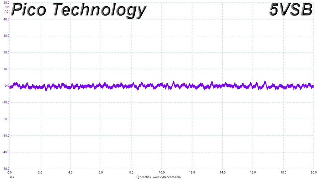
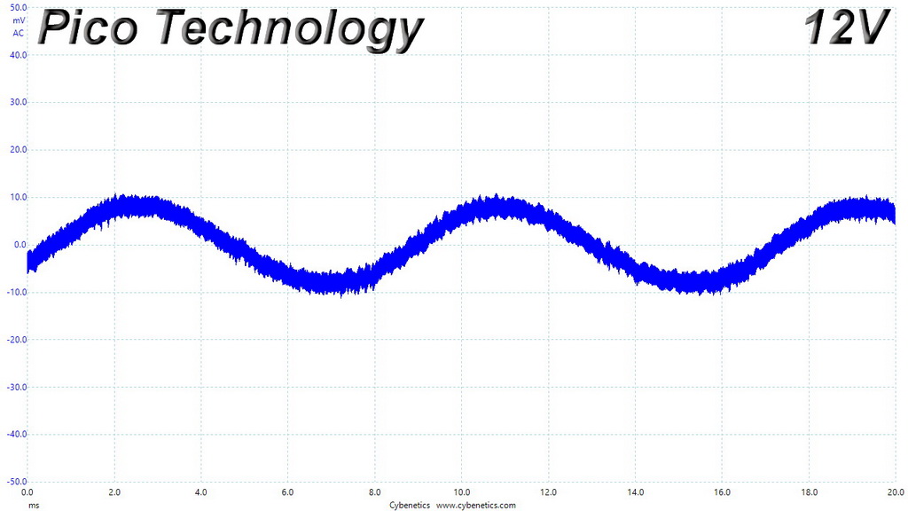
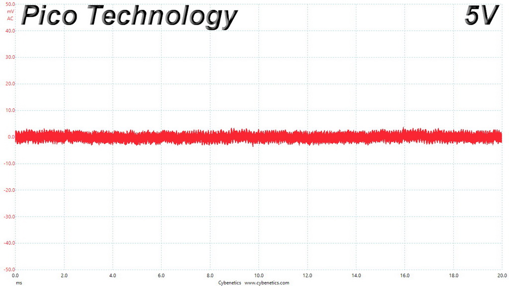
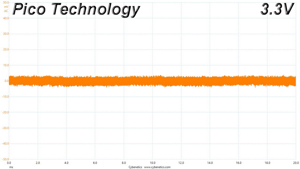
The following table includes the ripple levels we measured on the HPT650M’s rails. The limits, according to the ATX specification, are 120mV (+12V) and 50mV (5V, 3.3V, and 5VSB).
| Test | 12V | 5V | 3.3V | 5VSB | Pass/Fail |
| 10% Load | 29.0 mV | 6.9 mV | 6.9 mV | 10.4 mV | Pass |
| 20% Load | 17.8 mV | 4.8 mV | 6.2 mV | 16.0 mV | Pass |
| 30% Load | 15.9 mV | 5.7 mV | 7.1 mV | 18.3 mV | Pass |
| 40% Load | 16.6 mV | 5.5 mV | 7.2 mV | 19.9 mV | Pass |
| 50% Load | 17.9 mV | 6.6 mV | 8.3 mV | 19.3 mV | Pass |
| 60% Load | 19.2 mV | 7.4 mV | 8.8 mV | 18.1 mV | Pass |
| 70% Load | 19.0 mV | 7.7 mV | 10.1 mV | 16.4 mV | Pass |
| 80% Load | 20.2 mV | 8.0 mV | 11.2 mV | 20.4 mV | Pass |
| 90% Load | 21.8 mV | 8.6 mV | 11.7 mV | 19.4 mV | Pass |
| 100% Load | 23.5 mV | 9.3 mV | 12.1 mV | 19.4 mV | Pass |
| 110% Load | 24.7 mV | 9.9 mV | 13.2 mV | 19.4 mV | Pass |
| Crossload 1 | 17.9 mV | 7.6 mV | 10.9 mV | 7.1 mV | Pass |
| Crossload 2 | 23.5 mV | 7.5 mV | 8.8 mV | 11.4 mV | Pass |
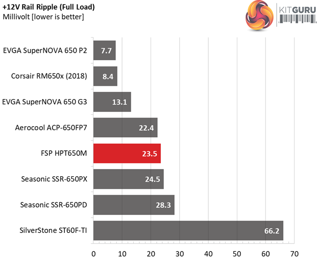
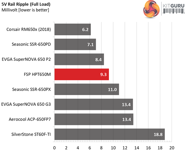
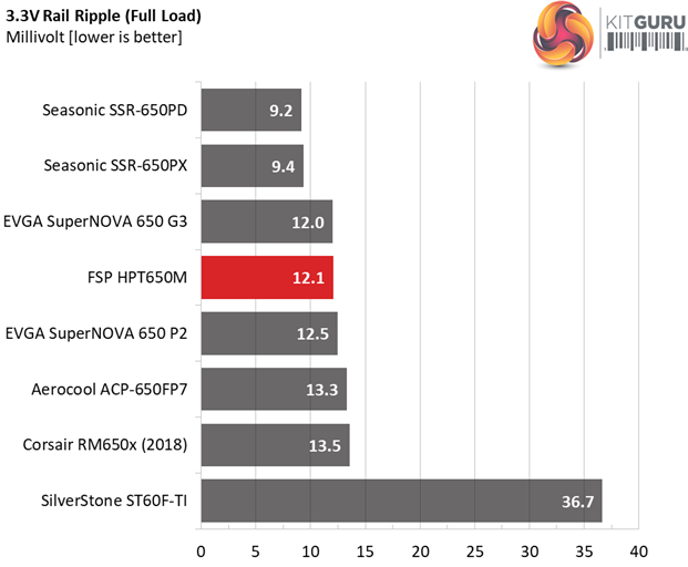
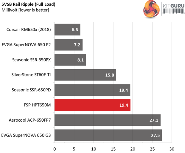
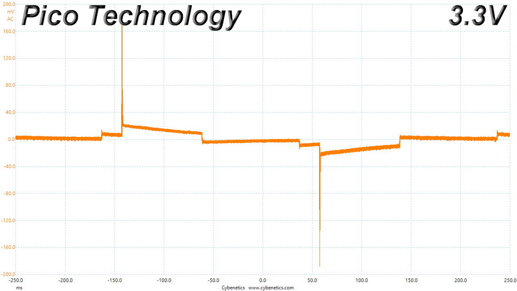
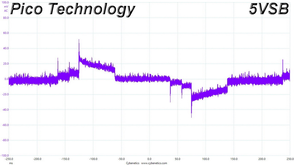
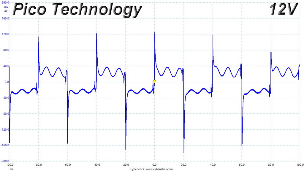
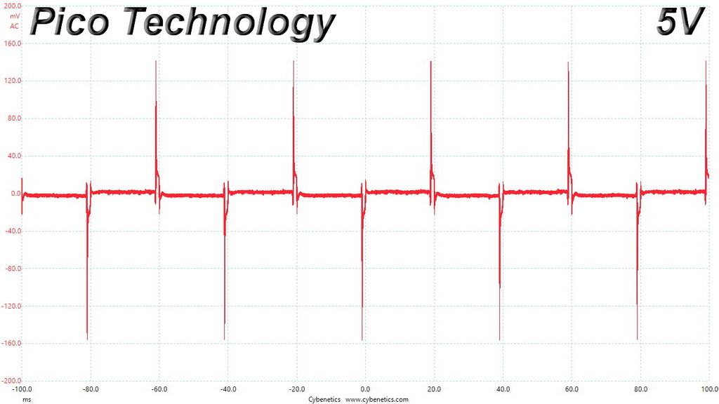
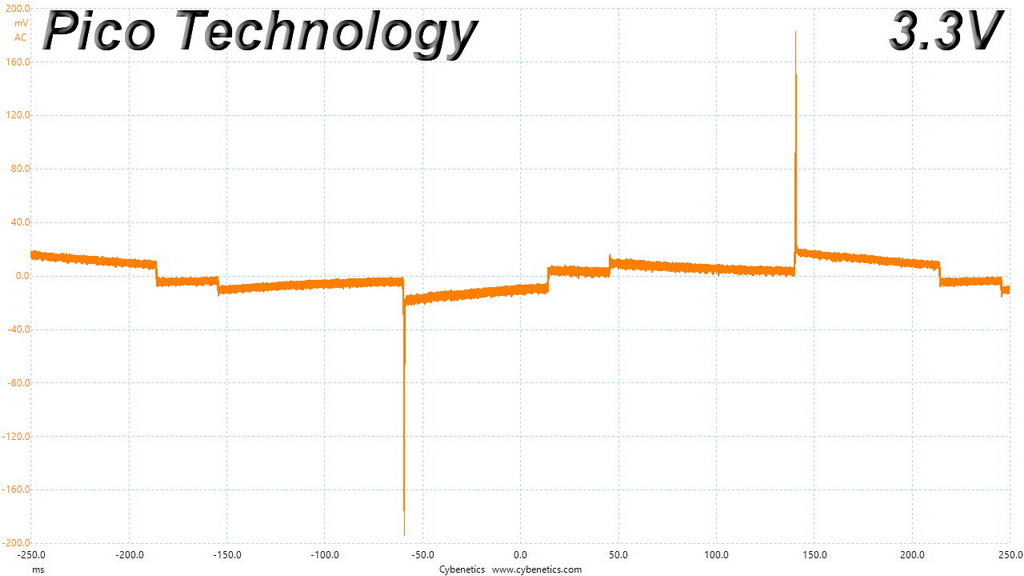
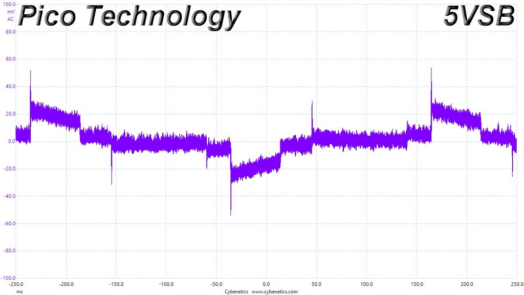
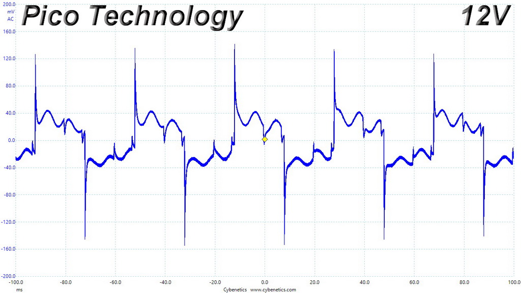
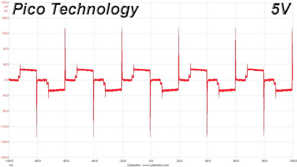
The ripple suppression is very good on all rails.
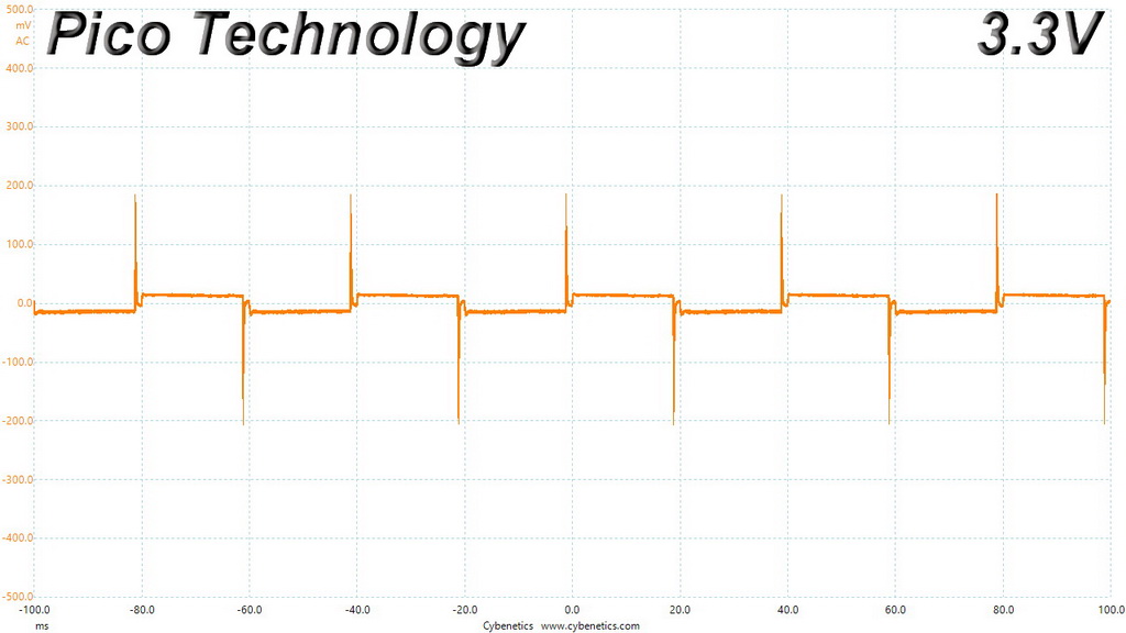
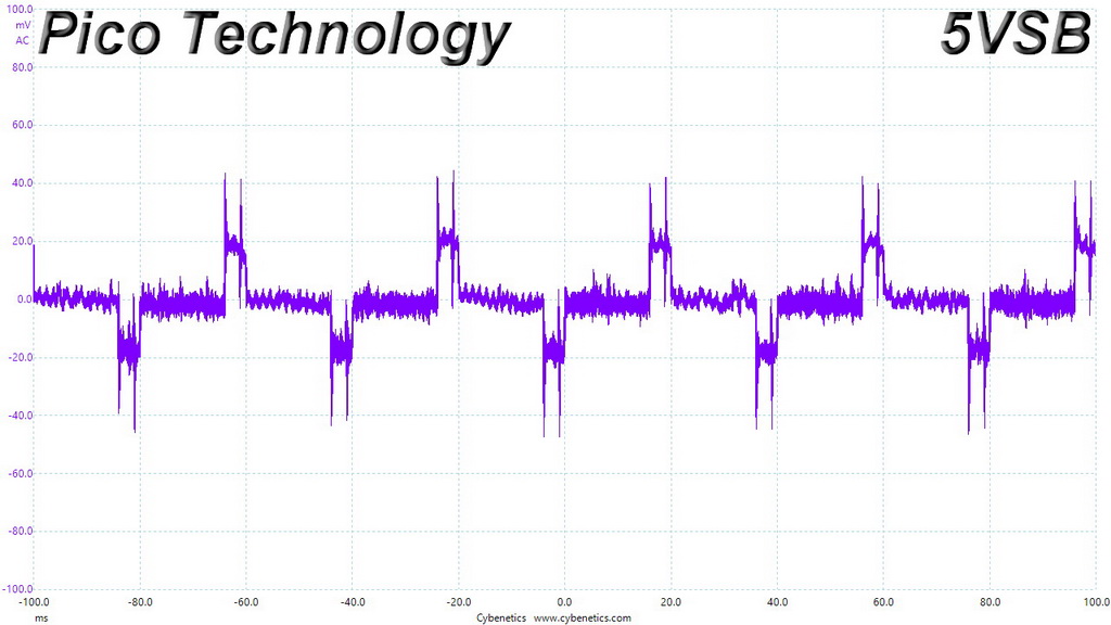
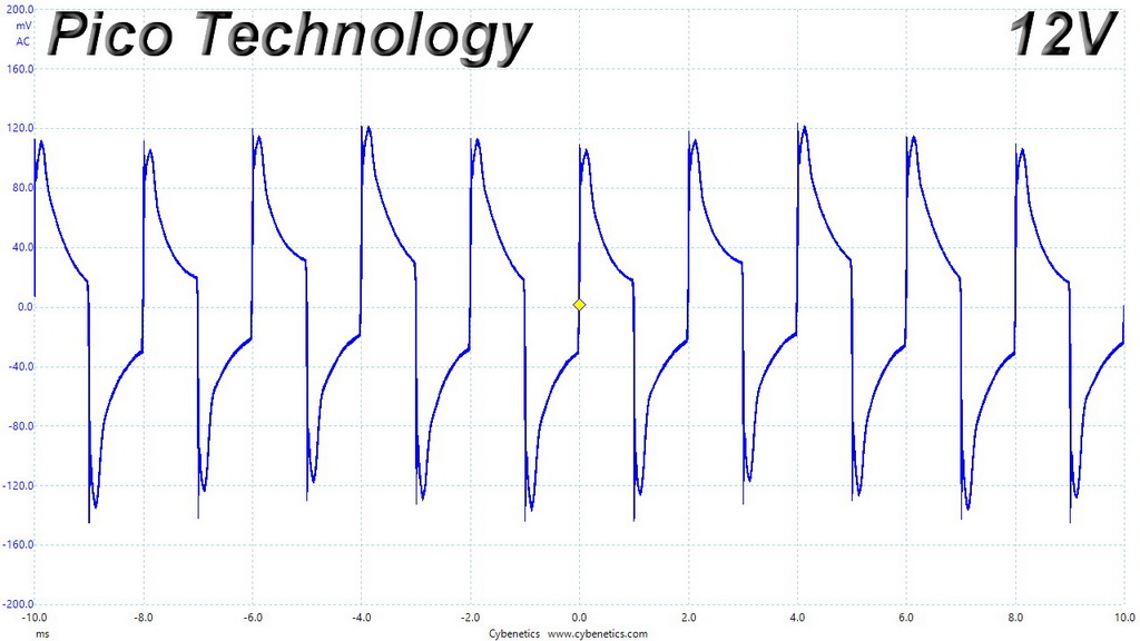
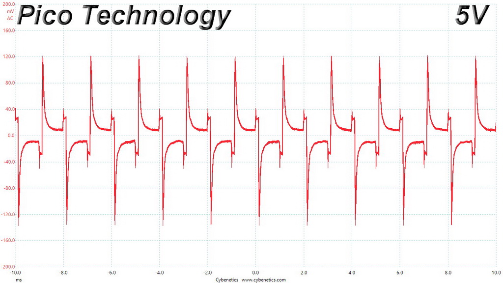
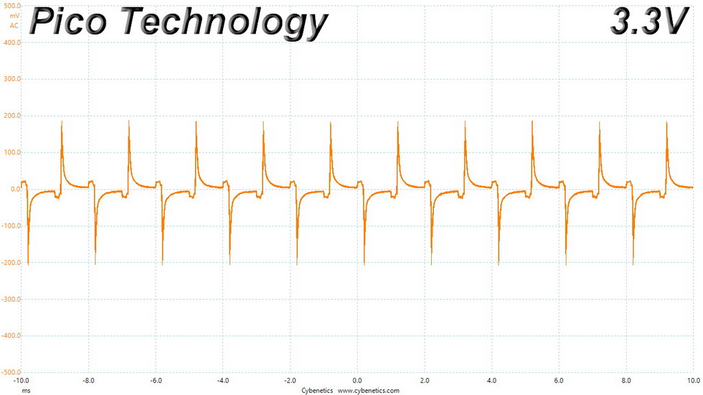
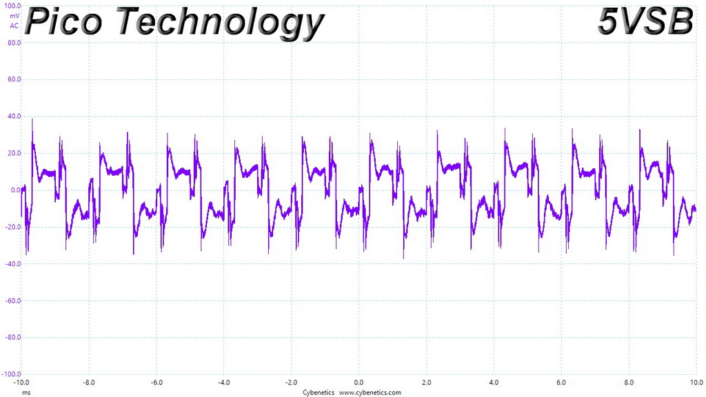
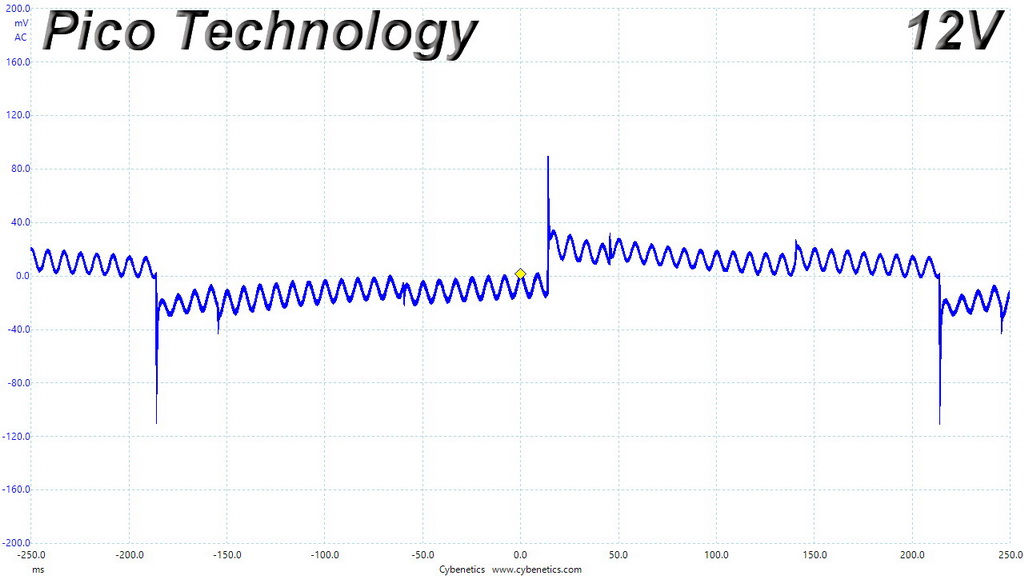
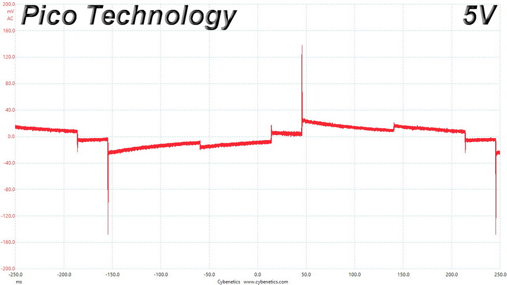
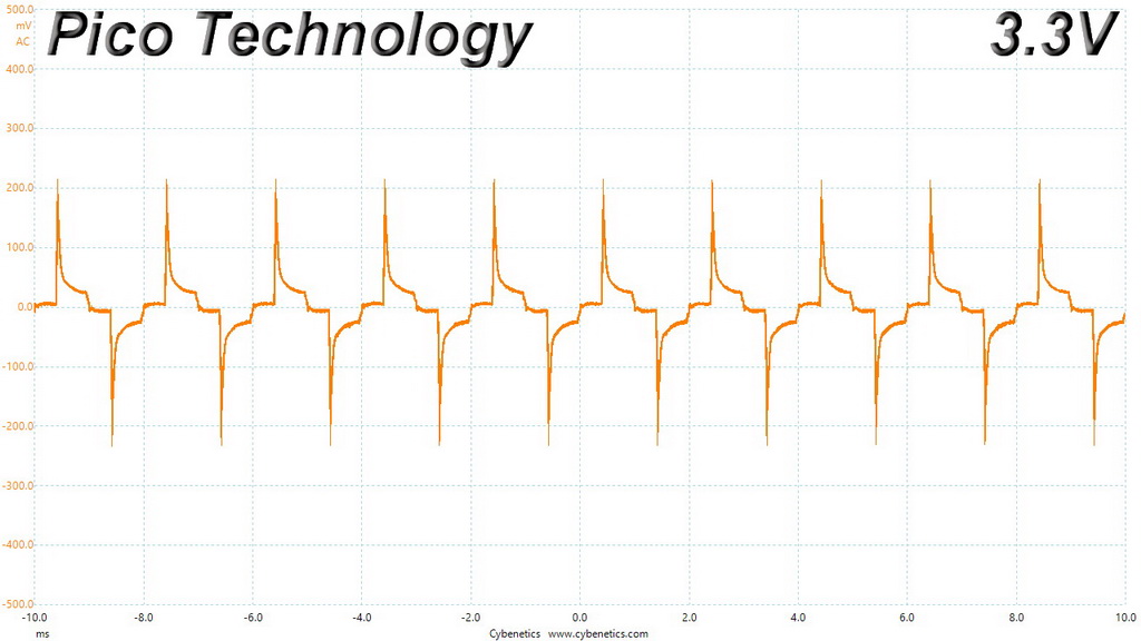
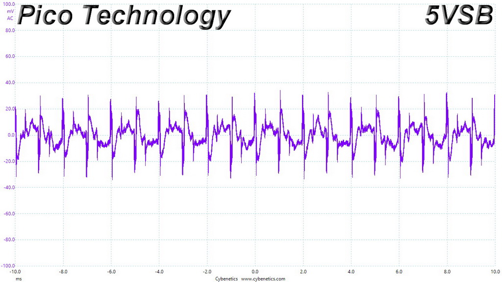
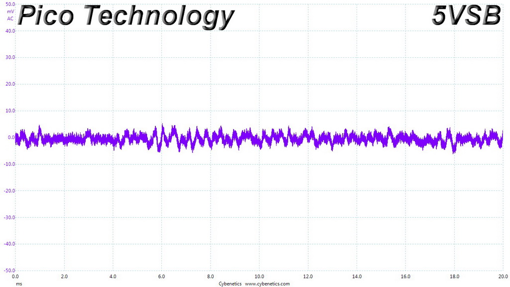
Ripple Oscilloscope Screenshots
The following oscilloscope screenshots illustrate the AC ripple and noise registered on the main rails (+12V, 5V, 3.3V and 5VSB). The bigger the fluctuations on the screen, the bigger the ripple/noise. We set 0.01 V/Div (each vertical division/box equals 0.01V) as the standard for all measurements.
Ripple At Full Load
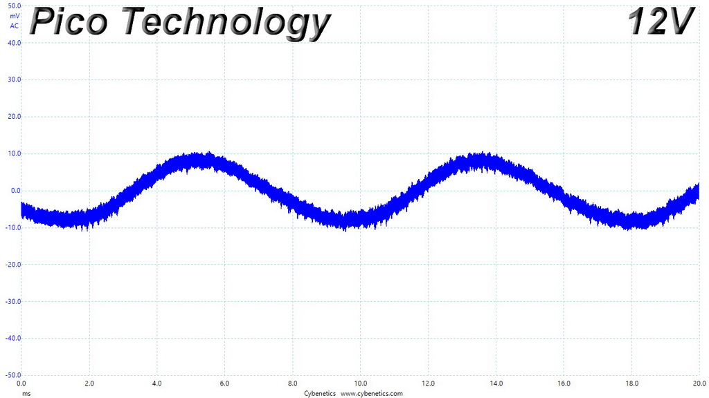
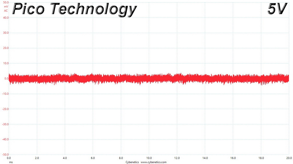
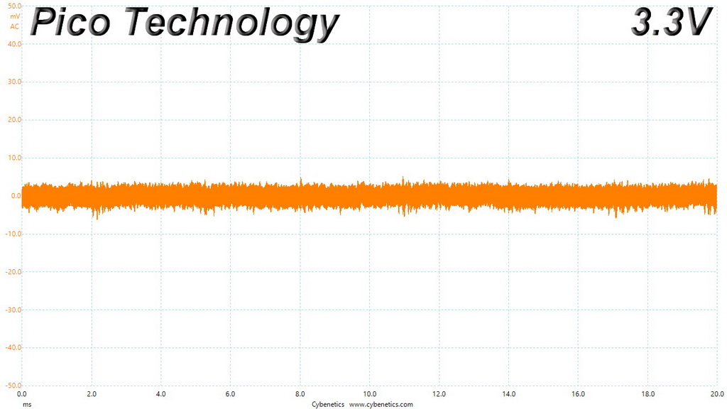
Ripple At 110-Percent Load
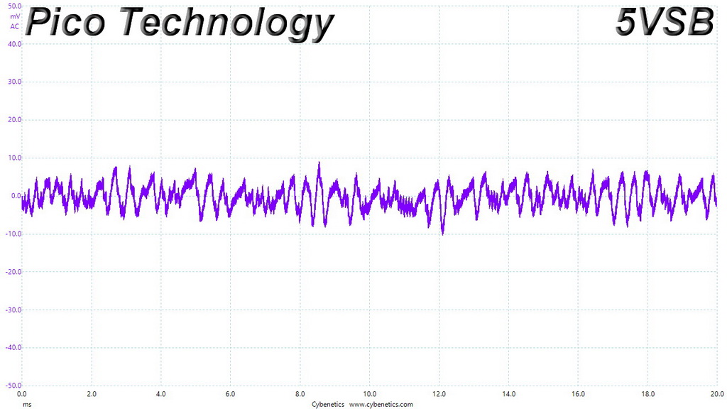
Ripple At Cross-Load 1
Ripple At Cross-Load 2
To learn more about our EMI testing equipment, please check out How We Test Power Supply Units.
EMI Results – Average Detector
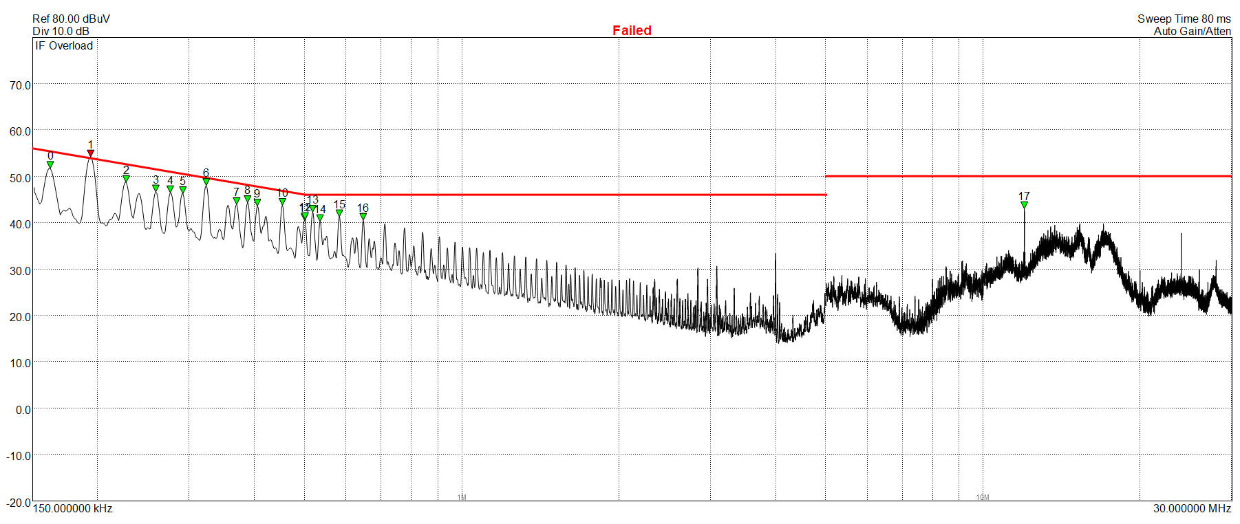
The conducted EMI is quite high, especially at lower frequencies, however only a single spur goes over the limit. Still it is enough to mark this unit as failed.
EMI Results – Peak Detector
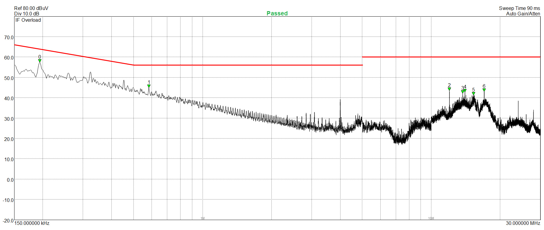
There is no sign of the high spurs that the AVG detector caught.
Performance Rating
The following graph shows the HPT650M’s total performance rating, comparing it to other units we have tested. To be more specific, the tested unit is shown as 100 percent, and every other unit's performance is shown relative to it.
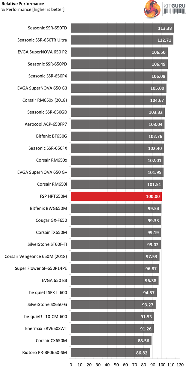
If the transient response was better and the hold-up time a bit longer, the overall performance would be notably higher.
Performance Per Dollar
The following chart may be the most interesting to many of you because it depicts the product’s performance-per-dollar score. We looked up the current price of each PSU on popular online shops and used those prices and all relative performance numbers to calculate the index. Note that all of the numbers in the following graphs are normalized by the rated power of each unit.
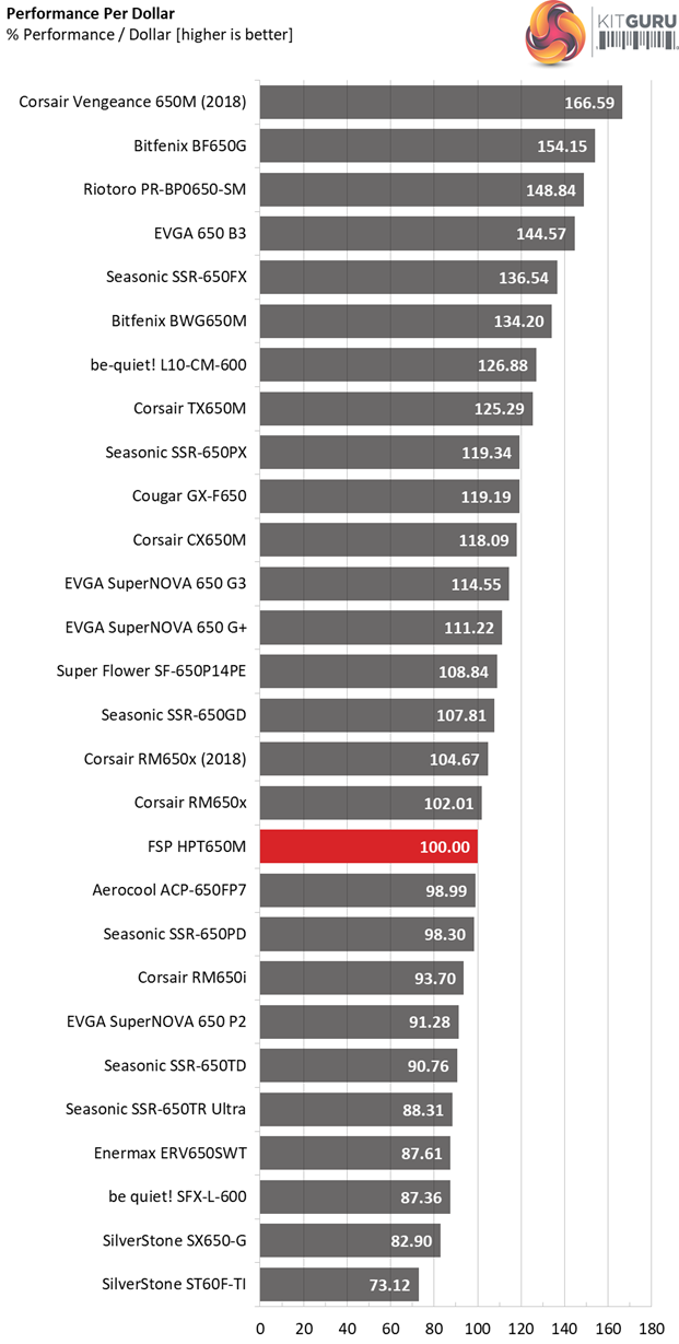
Currently FSP's offering costs about 11 bucks more than the Seasonic Focus Plus Platinum 650W, so inevitably the price per buck score is not so competitive. We believe that with a close to $100 price tag the HPT650M would be a much more appealing option.
Noise Rating
The graph below depicts the cooling fan's average noise over the PSU's operating range, with an ambient temperature between 30°C and 32°C (86°F to 89.6°F).
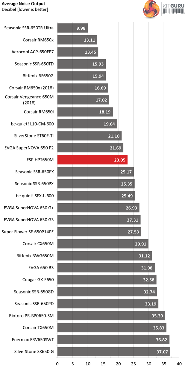
This is a very quiet PSU, taking the lead here from the SSR-650PX which is its major opponent. The difference is not so large though.
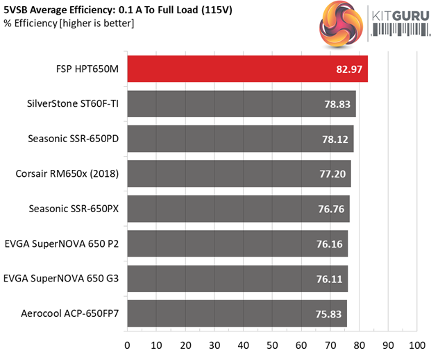
Efficiency Rating
The following graph shows the PSU's average efficiency throughout its operating range, with an ambient temperature close to 30°C.
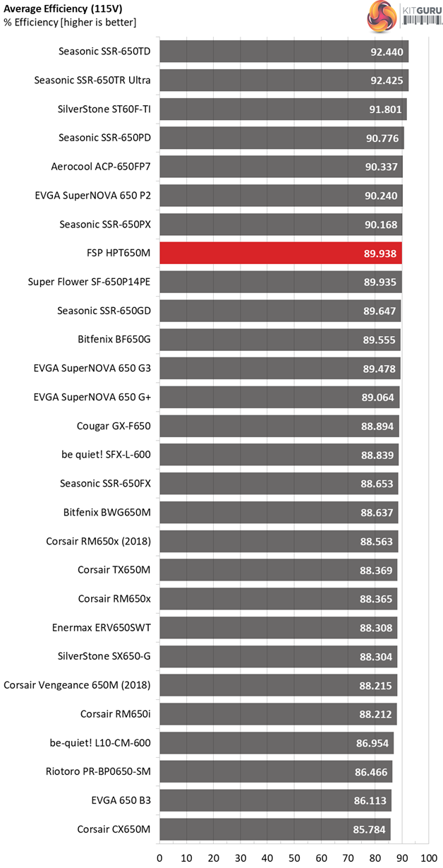
The platform is efficient, however the SSR-650PX performs better here.
The FSP Hydro PTM 650W retails for $120 in the US market, quite a steep asking price tag given that its major opponent, the Seasonic Focus Plus Platinum 650, is currently sold at $108. FSP should consider lowering this product's price, in order to keep up with the competition and increase the performance per buck ratio.
The major selling points of the HPT650M are the silent operation and the fact that it is one of the very few 650W units equipped with a pair of EPS connectors. However there is a catch here, for a weird reason FSP chose to install both those connectors onto the same cable, so if you have a power hungry CPU (or CPUs in case you have a server mainboard), then you might run into issues.
In my opinion it would be much better if FSP provided two dedicated EPS cables featuring only a single connector each, and made one of them compatible with the PCIe sockets. This way you would be only allowed two EPS and two PCIe connectors at the same time, or a single EPS and four PCIe connectors. Since this is a 650W unit clearly it cannot deal with two EPS and four PCIe at the same time, if the system that it feeds with power uses potent and probably highly overclocked parts.
The ripple suppression is great however there is room for improvement in the load regulation section. Moreover, the hold-up time is low and the transient response on all rails is mediocre, with the only exception being the 3.3V rail where performance is even worse! Although this rail is not so important any more – competitors perform better, so FSP has to keep up by applying the necessary fixes to the corresponding circuit.
The unit's transient response might not be good, however the situation gets better in the turn-on tests with the HPT650M delivering excellent results. Another commendable aspect with this unit is the highly efficient 5VSB rail which sets a benchmark for their competitors. At this time most OEMs don't care about improving this rail's efficiency performance so FSP are clearly standing out in the market.
The cooling fan is of high quality since you can never go wrong with a Protechnic Electric FDB fan, and the fan profile is super relaxed without creating problems for the platform's reliability, according to my IR camera's results.
The HPT650M certainly packs lots of great features into the design and the overall performance is high, however we still feel in some areas they fall short of the market leaders. We are currently awaiting UK stock and pricing.
Pros:
- Delivered full power at 47°C.
- High enough overall performance.
- Silent operation.
- Efficient.
- Highly efficient 5VSB rail.
- Good ripple suppression.
- Quality electrolytic caps.
- FDB fan.
- 2x EPS connectors (installed on the same cable though).
- Fully modular.
- 10-year warranty.
Cons:
- The soldering quality could be improved.
- Mediocre transient response on all rails (especially at 3.3V).
- The pair of EPS connectors is installed on the same cable.
- Low hold-up time.
- Limited number (3) of 4-pin Molex connectors.
- Not so compact dimensions.
KitGuru says: In general the HPT650M packs lots of interesting features into the design, however there are some areas where improvements are required. If FSP's engineers manage to address most of the issues that we highlight in the review, this product can be a good alternative to the highly popular Seasonic Focus Plus Platinum platform. A lower price, at around 100 dollars, would surely help, as well.
