

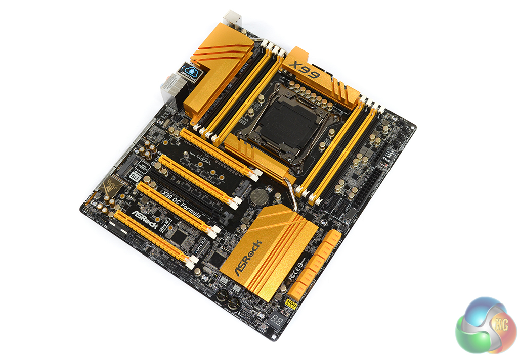
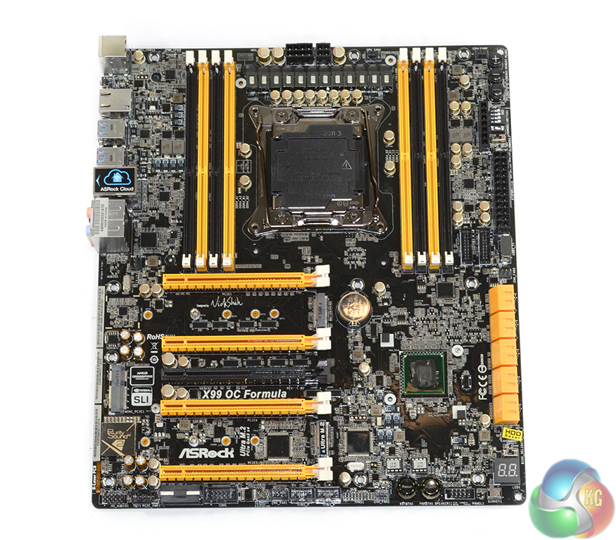
Sticking to its striking appearance for overclocking-orientated motherboards, the ASRock X99 OC Formula uses an eye-catching black and yellow scheme. Under certain lighting conditions the yellow heatsinks and connection ports seem to have a gold tint about them – especially the reflective blocks of aluminium cooling material.
Having proven popular with its previous OC Formula motherboards, ASRock has again called upon its Conformal Coating feature for the board's PCB and many of the components. The protective coating prevents conductive liquids from causing damage to the board and its electronic components. That's particularly convenient for overclockers who may be using water-based coolant (which soon becomes conductive due to dust contamination).
Even those with more exotic cooling solutions, such as liquid nitrogen, are going to see Conformal Coating as a convenience that allows them to spend less time insulating their motherboard with such a high precision.

In order to fit the necessary components on its PCB, ASRock extends the X99 OC Formula to the E-ATX form factor. This is unlikely to be an issue for most overclocking-geared users as it has been a common move by motherboard vendors for many generations with their extreme-performance parts.
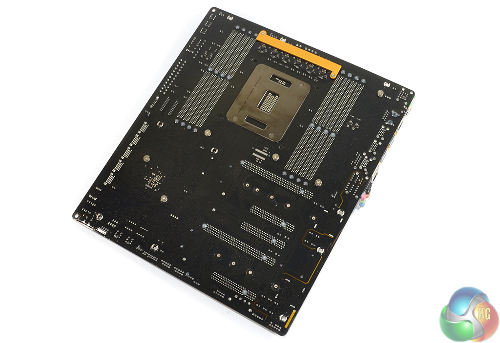
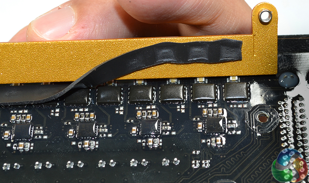
To emphasise the point that cooling is taken seriously on its X99 OC Formula, ASRock ensures that the rear MOSFETs are provided with their own strip of aluminium and a thermal pad.
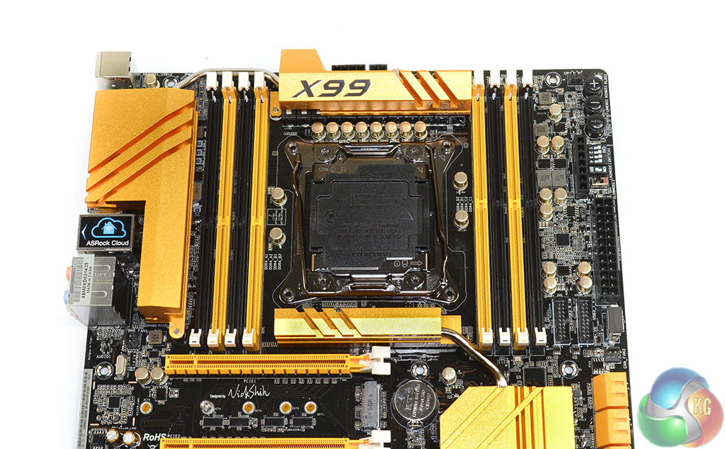
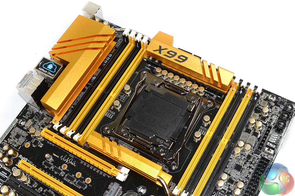
Eight DDR4 memory slots are split equally either side of the sizable LGA2011-3 CPU socket. The single-latch memory slots are all moved closer to the board's top edge, allowing for the primary PCIe expansion space to be populated. Up to 64GB of DDR4 memory can be installed by means of populating the eight slots with 8GB modules, or you can use 128GB if you can source 16GB memory sticks.
Aiming to cater for all user bases, ASRock gives the X99 OC Formula support for ECC and non-ECC memory via Unbuffered or Registered DIMMs. An Intel Xeon E5 series processor is required to use ECC memory – consumer Haswell-E parts do not support the spec.
For mainstream users, the workstation-grade ECC and Registered DIMM (RDIMM) specs are unlikely to be of any interest – it's the standard (G.Skill Ripjaws4, Corsair Vengeance, etc.) non-ECC, Unbuffered DIMMs you'll want. To workstation or server users, however, ECC and/or RDIMM sticks can be useful in providing error-prevention with high-density, high-speed memory configurations.
ASRock claims support for memory speeds in excess of 3400MHz, although, when using consumer-level DDR4 kits, that ability will be heavily influenced by the strength of a Haswell-E chip's Integrated Memory Controller (IMC) and the board's BIOS maturity.
Space around the X99 OC Formula's CPU socket gets tight when you start thinking about sub-zero cooling. It's the aluminium heatsink, in the area where the Northbridge was once sat many generations ago (just below the CPU socket), that is likely to cause the most interference with large LN2 pots. Cooling companies design for tall VRM heatsinks above the CPU socket, but those found in the Northbridge area are less common.
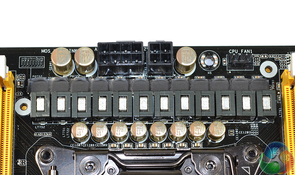
A twelve phase power delivery system feeds the LGA2011-3 CPU. ASRock suggests that the system can deliver up to 1300W of power, translating into an impressive 108W per physical electronic phase.
Looking more specifically at the components, ASRock opts for a 6-phase Intersil ISL6379 PWM controller to provide the overall VRM management. Six Intersil ISL6611A phase-doublers each take a single PWM input lane from the ISL6379 and convert it to two PWM output lanes. This allows ASRock to control up to twelve power delivery phases for the CPU.
Finding information for the ISL6379 PWM chip is very difficult, although numerous sources suggest that it is a ‘hybrid' analog/digital controller. If that is indeed the case, it's the analog section of the controller that is to thank for ASRock's rapid voltage switching frequency which leads to positive power consumption numbers under static loads (as we will outline later). However, some of the enhanced accuracy and future-looking voltage level projection may be missing compared to a purely digital component.
Twelve unmarked chokes, each of which ASRock rates for a 60A output, are joined by 24 Fairchild FDMS3660S dual N-channel MOSFETs. The front dozen MOSFETs are electronically linked in parallel with the rear dozen, allowing the twelve available PWM channels to provide overall control for every transistor. The X99 OC Formula features roughly $22 worth of MOSFETs just for the CPU (although the OEM probably pays less by bulk ordering).
I'm actually quite surprised to see ASRock opting for the Fairchild MOSEFTs when some of its previous OC Formula parts used Texas Instruments' NexFET solutions, which are widely believed to compete with International Rectifiers' IR355x PowIRStage alternatives for the MOSFET crown. The move would imply that ASRock has strong confidence in the Fairchild components, but performance numbers from extreme overclockers will provide the best comparison data.
ASRock also uses Nichicon ‘Platinum' capacitors, rated for 12,000 operating hours at 105°C, for power delivery functions. Scale that running temperature down to a realistic operating value and it translates into a very long operational lifespan for each capacitor.
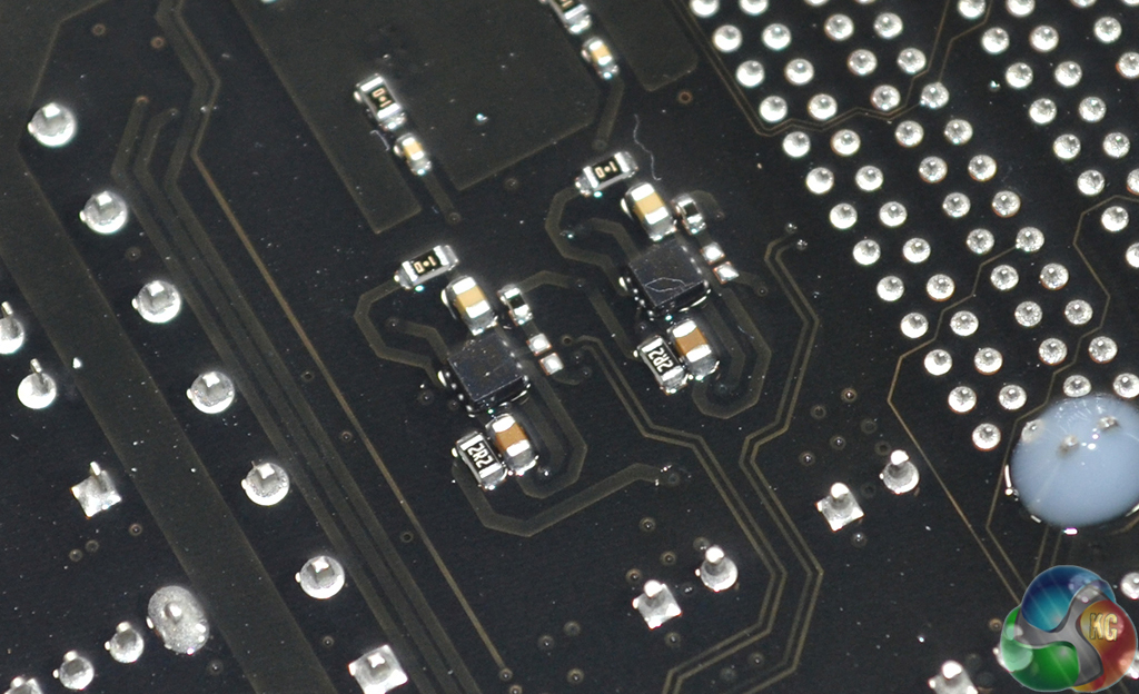
Two more ISL6379 PWM controllers manage the X99 OC Formula's 4-phase memory power delivery system. ASRock uses ‘Premium Memory Alloy Chokes‘ which are suggested to deliver their current with reduced temperatures.
The Conformal Coating makes it difficult to read what is written on the electronic components, although I did notice Sinopower SM4337 MOSFETs in the memory's vicinity. There is also a pair of Richtek RT9045 regulators which (presumably) work with DDR voltage applications.
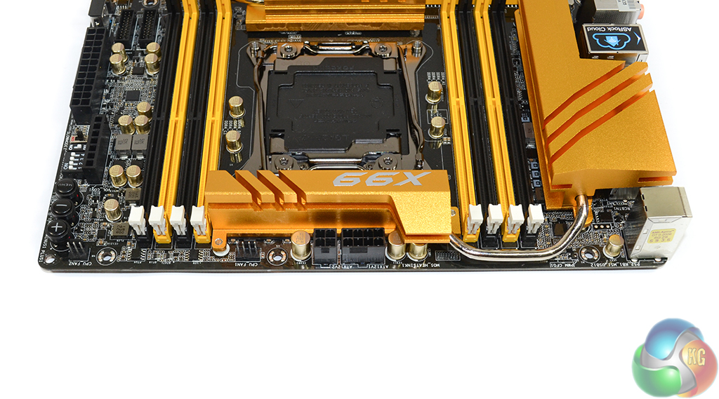
ASRock equips the X99 OC Formula with two CPU power connectors – one of the 4-pin variety in addition to the common 8-pin version. This is a smart move by ASRock because that additional 4-pin connector is useful when extreme overclockers are pushing heavy voltage levels.
Two CPU fan headers are positioned along the top edge, both of which are controlled through the same CPU fan channel.
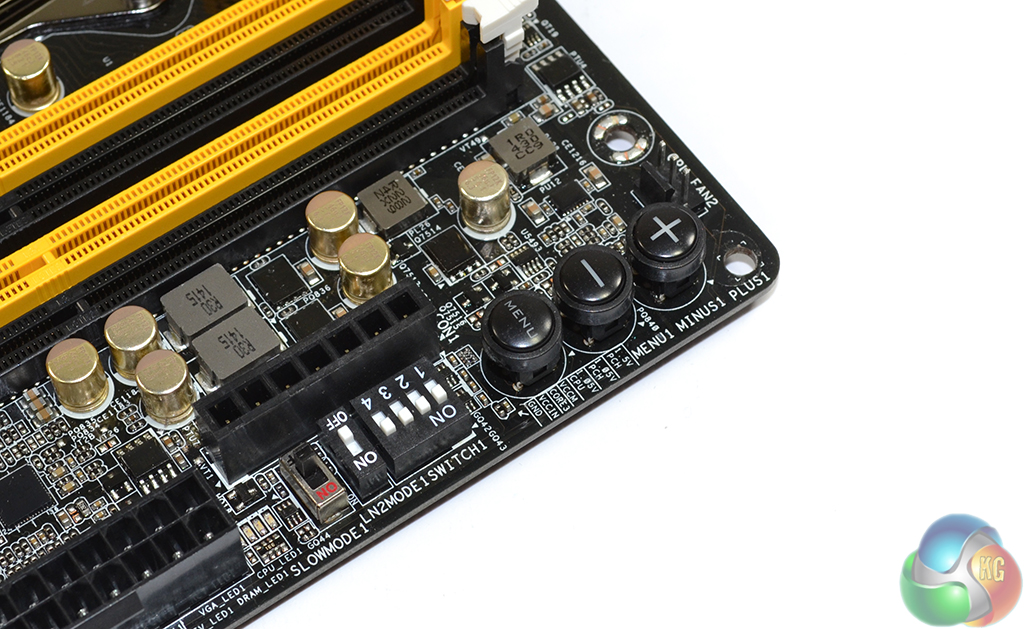
The plus and minus buttons in the board's top-right corner control adjustments to the BCLK. ASRock includes the staple overclocker and benchmark features – slow and LN2 mode toggles, PCIe slot disable switches, and voltage reading points called V-Probe.
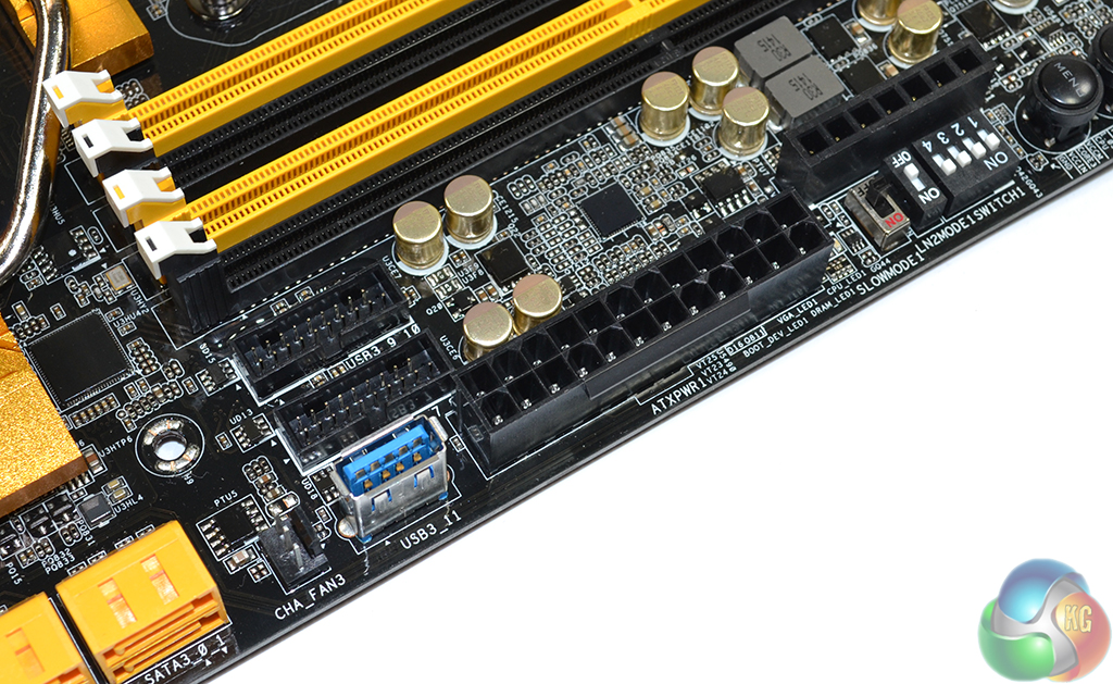
A standard USB 3.0 port is joined by two outwards-facing internal USB 3.0 headers, adjacent to the 24-pin connector. A 4-port ASMedia ASM1074 hub is used to provide two headers worth of USB 3.0 outputs from a single input.
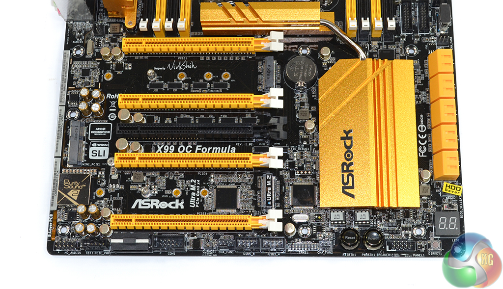
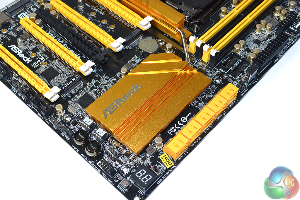
4-way SLI and CrossFire are both supported by the X99 OC Formula, provided a 40-lane CPU is used. The yellow slots are to be used for graphics cards, the first and third of which are hard-wired for up to sixteen PCIe lanes, with the other two linking by a maximum of eight lanes. ASRock recommends installing any necessary expansion devices in the black connector (which shares its bandwidth with the PCIe 3.0 x4 Ultra M.2 slot).
The uppermost (PCIE1) PCIe slot is used for a full x16 link to one card, while two cards are given sixteen lanes each, as well as a cooling gap, using the PCIE1 and PCIE4 connectors. Three cards rely upon the first three yellow connectors, and are linked to the CPU at PCIe 3.0 x8/x8/x16. 4-way configurations use all of the yellow PCIe connectors in an x8/x8/x8/x8 link.
I have no problems with ASRock's PCIe configuration; the layout is smart and 4-way SLI/CrossFire can be used alongside a PCIe 3.0 x4 SSD in the Ultra M.2 slot.
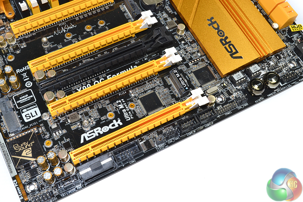
Situated next to the SLI and CrossFire badges is a mini-PCIe connector. The 5Gbps PCIe 2.0 port can be used to house a WiFi card, without competing against graphics cards for the precious expansion slots.
Standard connections, such as front panel and USB 2.0 headers, are found along the motherboard's bottom edge. ASRock also includes COM and TPM connectors, as well as a ThunderBolt header, presumably to tie in with the PCIe clock speed.
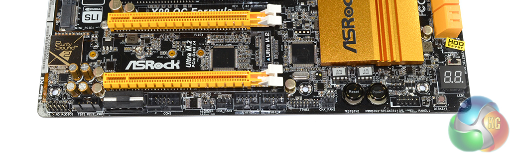
Additional connectors come in the form of onboard power, reset, and Direct Key buttons. ASRock positions these buttons away from the DRAM area where they could freeze due to sub-zero cooling vapors, but a graphics card installed in the lowest slot will block their access. Positioning of onboard overclocking buttons can be a task that is highly likely to cause interference issues for at least one set of users.
A BIOS selection switch allows users to load the backup system in the case of a crash. ASRock's Dr. Debug LED displays error codes.
A downwards-facing 4-pin molex connector is used to provide additional power to multi-VGA configurations. Its position and orientation are both smart – a cable can be routed behind the motherboard tray and hidden with ease in a chassis environment.
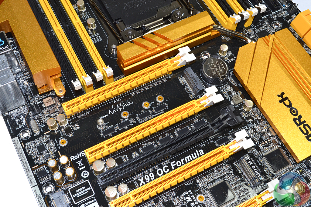
Sat beneath the primary PCIe slot, ASRock links its ‘standard' M.2 connector with four chipset-fed PCIe 2.0 lanes. This gives a bandwidth capability of 20Gbps, which is twice as fast as the typical 10Gbps M.2 solution found on most Z97 boards (or as a backup measure for some X99 parts). A SATA 6Gbps lane can also be fed to the connector for use with M.2 SATA devices, although we aren't sure why you'd want to use such a drive (one less component to lose, perhaps).
ASRock's Ultra M.2 slot sits above the motherboard's lowest PCIe connector. Four CPU-fed PCIe 3.0 lanes are fed to the connector, giving it a bandwidth capacity of 32Gbps. As we have already pointed out, the Ultra M.2 connector can be used at all times with a 40-lane CPU, irrelevant of how many graphics cards are connected.
We tested ASRock's Ultra M.2 connector, with Samsung's ultra-fast XP941 SSD, in our review of the Z97 Extreme6 and were thoroughly impressed by its throughput capability.
Drives up to 110mm-long can be installed in both of the M.2 connectors. Unfortunately the M.2 connectors do not support any RAID function with each other. ASRock tells us that this is because their connections are provided from different sources (the CPU and the X99 chipset).
A future improvement could come via support for RAID with M.2 SSDs. ASRock's PCIe slot configuration leaves eight PCIe 3.0 lanes from the CPU spare when four graphics cards are used. Using an additional switch to split this eight-lane link down to a pair of four-lane links would be enough to drive two Ultra M.2 connectors. And with the PCIe 3.0 lanes originating from the same source (a 40-lane CPU), there is the potential for RAID functions to be supported.
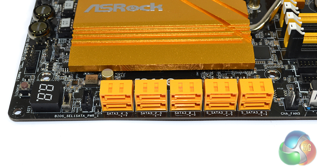
Ten SATA 6Gbps ports, all of which are delivered by the X99 chipset, are found on the X99 OC Formula. Only the six ports to the left (SATA3_0 to SATA3_5) support RAID 0, 1, 5, and 10. The four remaining ports do not support any form of RAID, and S_SATA3_3 shares its link with the M.2 connector.
ASRock's HDD Saver feature is supported by the X99 OC Formula, the header for which is found left of the SATA ports (in the above photograph). HDD Saver can control up to two SATA drives (with the supplied cable) by switching them off via software as required for privacy, durability, or power saving purposes.
Five months ago I would have criticised ASRock for the decision to leave out SATA Express. Wind the clock forward almost half a year and it is clear that M.2 is the (far) more popular interface (and probably will be for the near future), so the lack of SATA Express functionality doesn't seem like a huge issue.
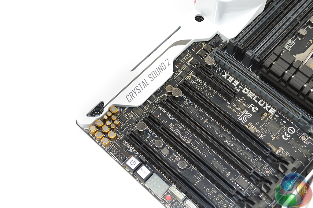
Realtek’s ALC1150 codec, with its 115dB signal-to-noise ratio (SNR), provides the foundation for ASRock's Purity Sound 2 audio system. EMI shielding and a distinct PCB pathway is used to minimise signal interference.
A pair of Texas Instruments NE5532 operational-amplifiers are used to provide support for 600 Ohm headsets, while Nichicon fine gold series capacitors (largely 100µF and 10V specification) filter the audio signals.
You may be quick to question the relevance of an enhanced audio solution on an overclocking-geared motherboard. The fact of the matter is that many hobbyist overclockers will purchase one motherboard for their usage. That board has to carry out their day-to-day computing tasks, which could include gaming or audio playback, and then be stripped down and stuck on the bench for overclocking sessions, when they occur.
With that point in mind, motherboard vendors are challenged with creating a board that caters for all users and also has enhanced overclocking potential to boot. And that's why we see many ‘general-usage' and gaming features popping up on overclocking-orientated motherboards.
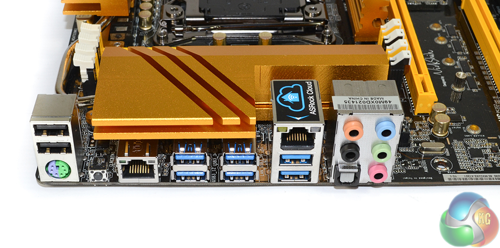
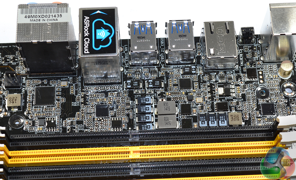
Six USB 3.0 ports are found on the rear IO panel, four of which are provided by the board's second ASMedia ASM1074 hub controller. A pair of USB 2.0 ports and one PS/2 connection are provided for overclockers or gamers who prefer the connections for their peripherals.
Two Gigabit Ethernet ports are utilised – one of which is provided by Intel's I218-V chipset, with the other originating from an onboard Qualcomm Atheros AR8171 PCIe-based chipset. The Qualcomm NIC is used to provide support for the ASRock Cloud network-based services.
Completing the rear IO ports are audio connections and the always-convenient clear CMOS button.
Called ‘XXL Aluminium Alloy‘ heatsinks by ASRock, two metal blocks are connected via a flattened heatpipe and tasked with cooling the intense MOSFET system. The chipset and ‘Northbridge' heatsinks are also connected via a heatpipe to ensure a satisfactory level of cooling for the X99 PCH.
Since ASRock switched to its larger VRM heatsinks, the small cooling fan that was fitted to Z77 and Z87 versions of the OC Formula has been removed. Also gone are the pre-fitted watercooling barbs. Those are both positive points; feedback suggested that watercoolers prefer to choose their own fittings (and VRM waterblocks, for that matter), while overclockers are likely to use a dedicated fan for cooling the MOSFETs during heavy, benchmark-induced loads.
Avid memory overclockers will notice the potential for interference between large LN2 memory cooling pots and the left VRM heatsink. The motherboard heatsink should be short enough to fit beneath LN2 memory cooling pots which tend to extend at a higher position.
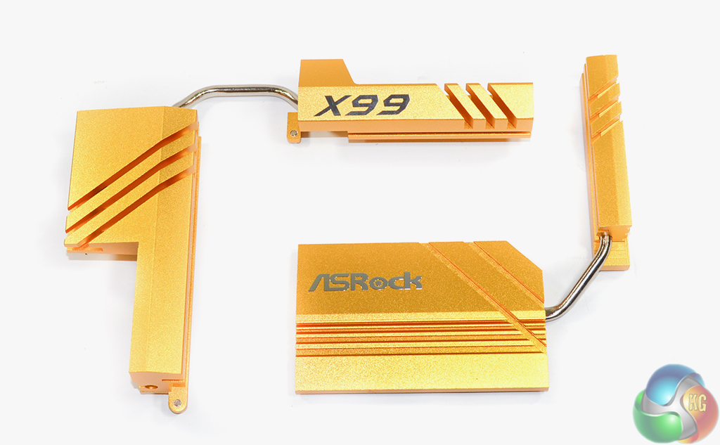
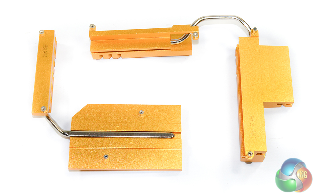
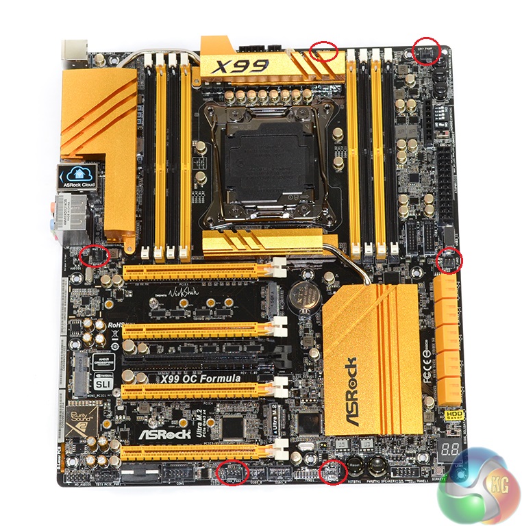
Removing the two sets of heatsinks is a task that is left intentionally simple by ASRock. A number of easy-to-access screws hold each heatsink in place and they are manufactured and fitted to come off easily. This is a positive point for those looking to upgrade their VRM cooling capacity, or overclockers who regularly switch between the stock and an after-market heatsink, depending on their usage scenario.
The particularly minuscule level of contact between the chipset and its heatsink implies that the metal is more for appearance than performance. I do not see the need for the ‘Northbridge' heatsink, either; its positioning causes the potential for interference and it doesn't cool anything of particular worth (or heat output).
We wouldn't be surprised to see manufacturers such as EK providing VRM or full-cover waterblocks for the X99 OC Formula. An individual VRM heatsink that covers both MOSFET areas seems the most likely solution; making a full-cover block span from the MOSFET area down to the chipset doesn't seem to be possible with the path restrictions.
Six fan headers are provided on the X99 OC Formula, four of which are 3-pin. Distribution of the fan headers is smart – four are accessible from the CPU socket, and two are placed along the board's bottom edge.
ASRock employs two Nuvoton SuperIO chipsets – the NCT6791D and NCT6683D-T. While they can both perform the same voltage, temperature, and fan speed monitoring functions, I'd wager that the more advanced NCT6683D-T is included for its enhanced fan control and SPI flash capabilities.

Hey Luke, what attracts me to this board are the 2 x M.2 slots. Unfortunately you cannot run them in hardware Raid 0, but I believe you can software raid them in Windows. The other thing is do you know if the 5 year warranty is available worldwide? Or just the US/Europe?