

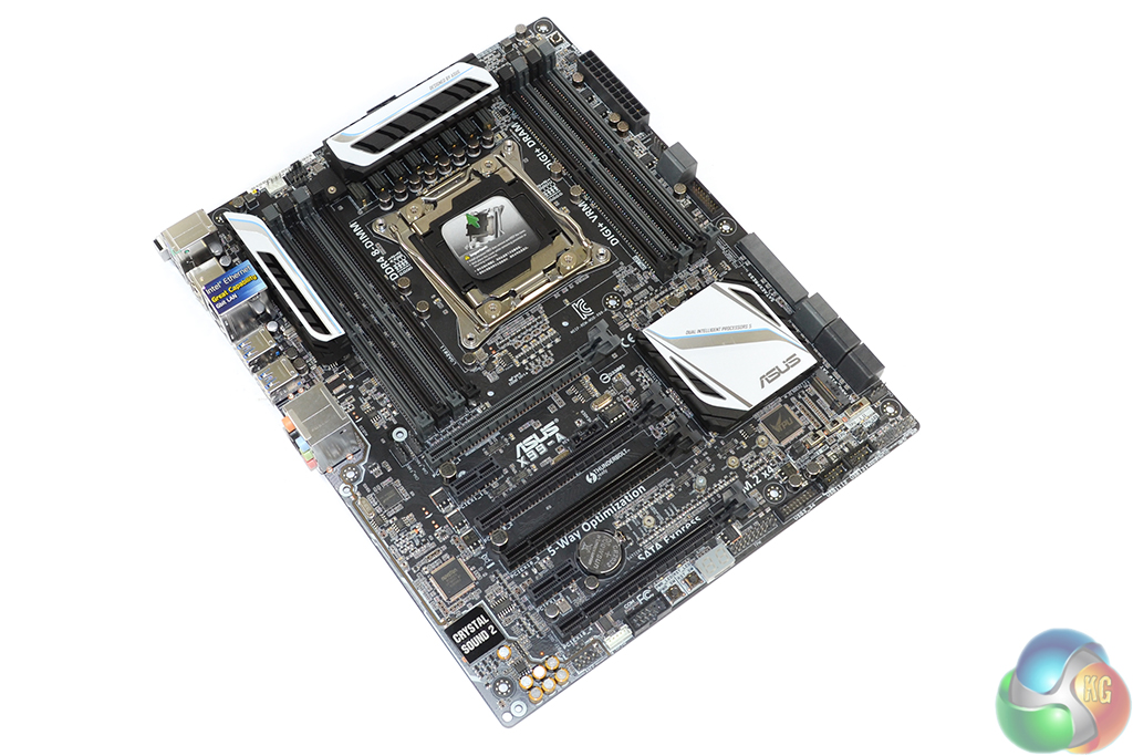
Asus continues the striking black and white adoption for its X99-A motherboard. Although it is not anywhere as near as prominent as the design used by the company’s X99-Deluxe, the colour scheme still represents an eye-catching design.
There has been a large amount of interest in white and black components as of recent.
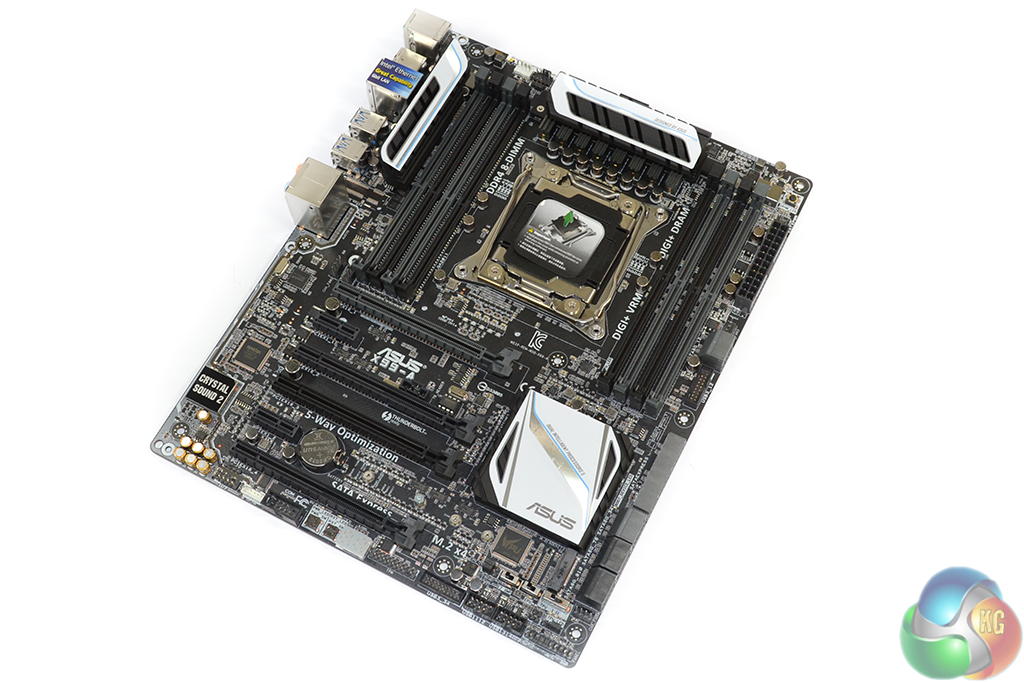

A smart move by Asus is the decision to use a fully-black PCB. Many lower-cost solutions see the use of an ugly brown PCB that can quickly destroy the attractiveness of a colour-coordinated build.
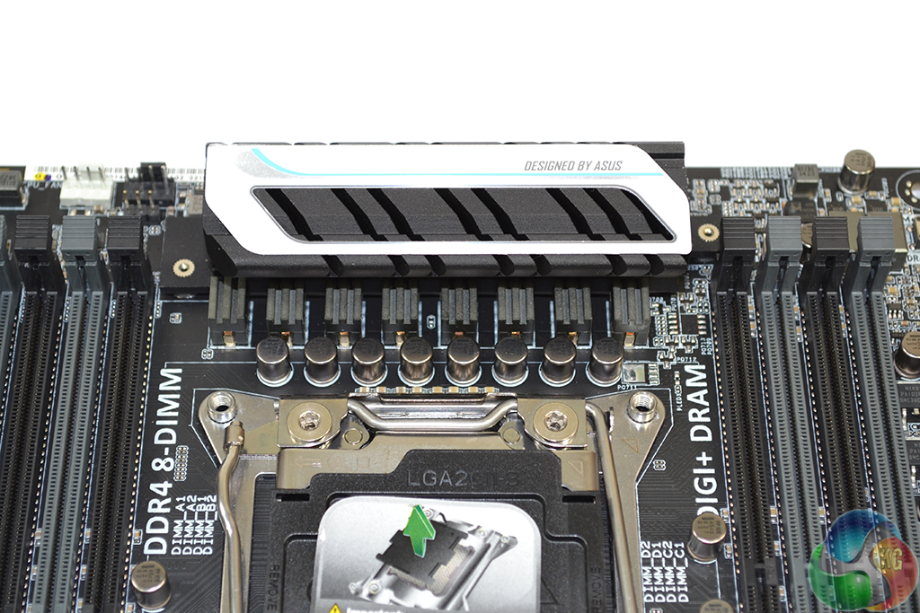
A strip heatsink behind the CPU VRM section cools additional power delivery components.
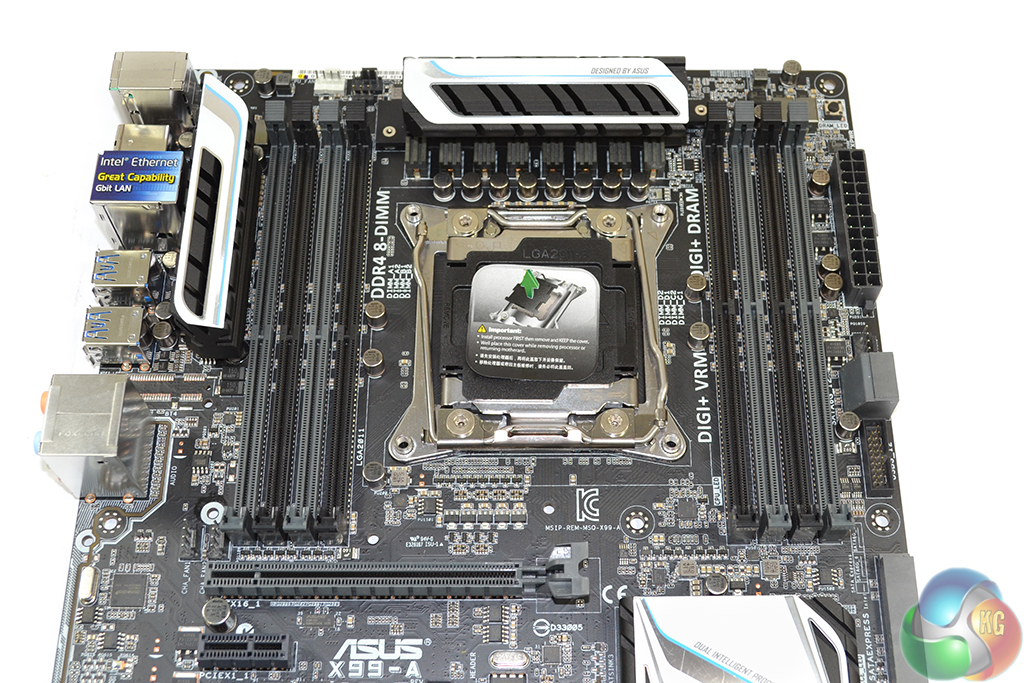
The large LGA 2011-3 CPU socket sits between two pairs of 4-DIMM banks. Asus’ OC Socket adds pins to the standard CPU socket in order to boost voltage delivery potential. The claims of higher CPU clocks can only really be tested with extreme voltage levels and cooling solutions; we have found very little difference between socket types at standard voltages.
Asus does, however, suggest that the greater flexibility with cache frequency that OC Socket provides, can be beneficial to high-speed memory performance.
Up to 64GB of DDR4 memory can be installed in the X99-A. Asus claims support for 3200MHz DRAM speeds, although that will be heavily related to whether the current BIOS implementation can run with those speeds or not.
As was the case with the X99-Deluxe, Asus uses eight power phases to feed an LGA 2011-3 processor. CPU VRM management is taken care of by the Digi+ VRM ASP1257 controller.
Eight ON Semiconductor NTMFD4C85N (labelled 4C85N) MOSFETs are found beneath the VRM heatsink. Around the back of the motherboard, eight International Rectifiers IR3535M synchronous buck converter drivers are situated under the strip heatsink. 10K-rated capacitors are also used throughout the motherboard.
The memory uses two Digi+ ASP1250 controllers and a four-phase design (two for each 4-DIMM bank) which sees International Rectifiers’ respected IR3553M PowIRstage components used.
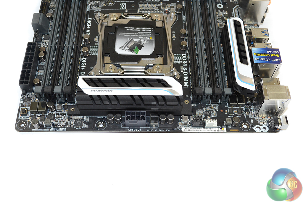
Two 4-pin fan headers, both of which are allocated to the CPU control channel, as well as the 8-pin power connector are found along the motherboard’s upper edge.
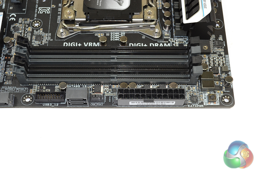
Asus places the 24-pin power connector further up the motherboard’s right-edge than usual. That said, the positioning is unlikely to cause cable management worries on most decent cases. The ever-convenient MemOK button is sat in the top-right corner.
To segregate them from the other ports, two SATA 6Gbps connectors are sat adjacent to a 4-pin chassis fan port and an outwards-facing USB 3.0 header. The two USB 3.0 connections originating from the header obtain their bandwidth from the X99 chipset.
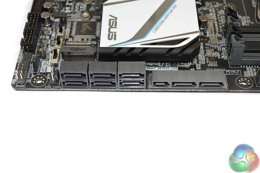
The remaining eight SATA 6Gbps ports are found further down the board’s right side. Two of those ports double up as the 10Gbps SATA Express connector. Asus’ chipset bandwidth allocation decision sees the SATA Express port given its own PCIe 2.0 x2 link that is not shared with other connectors.
Ports 1-6 (coloured in the lighter shade of grey) should be used for true RAID support from the Intel RST driver. The remaining four darker-coloured ports are forced to operate from the generic Windows AHCI driver, and should be used for drives where speed is not critical.
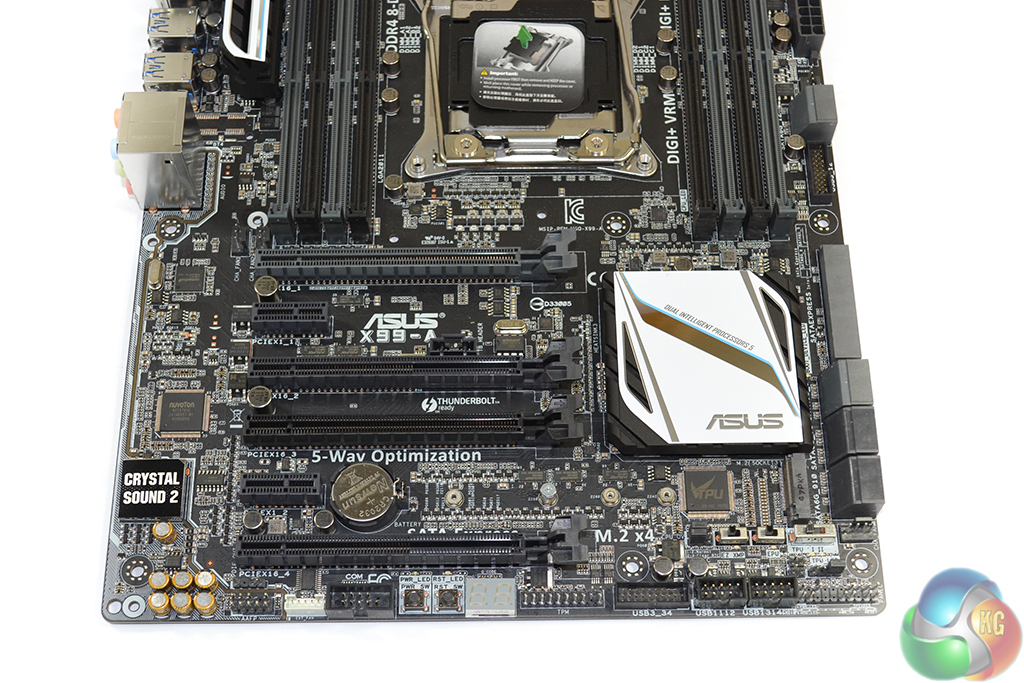
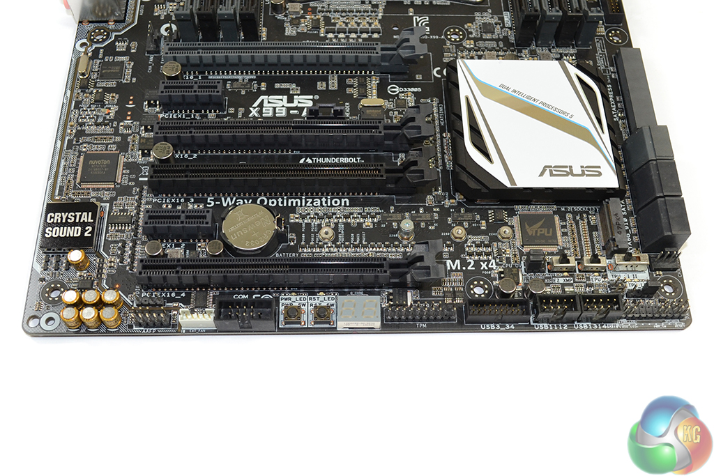
Four full-length PCIe slots are fitted to the X99-A. But that’s where the expansion slot simplicity ends.
That second full-length slot runs off the chipset’s PCIe 2.0 lanes and is limited to x1 or x4 connections. The x4 link is achieved by stealing bandwidth from two ASM1042AE-fed rear USB 3.0 ports and the upper PCIe 2.0 x1 connection.
Graphics support on the three remaining PCIe 3.0 full-length slots is not straightforward, either. Let’s first focus on the configuration with a 28-lane CPU (the 5820K) installed.
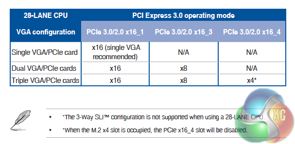
The slot configuration can be set as x16/x0/x0 + x4 M.2 for a single graphics card. A two-card configuration will set x16/x8/x0 + x4 M.2. A three-card setup forces the M.2 PCIe 3.0 x4 link to be sacrificed to give four lanes to the lowest expansion slot, forging an x16/x8/x4 allocation. That is no good for anything more than 2-card SLI (x8 or x16 links are necessary), and the x4 link is also frowned upon, although officially supported, for CrossFire use.
So, with a 28-lane CPU, you’re limited to M.2 PCIe 3.0 x4 plus 2-way SLI/CrossFire in a high-bandwidth link. Alternatively, you can run no M.2 connection and 3-card CrossFire using a less-than-ideal x4 link for the third card (the chipset-fed PCIe 2.0 port could be used for another x4 graphics link, but it’ll be performance-limiting).
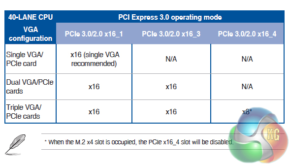
Now focusing on a 40-lane chip (the 5930K or 5960X), 3-card SLI/CrossFire, with high bandwidth links, is supported. But that’s not without its own sacrifice.
Up to two x16-linked graphics cards can be used alongside the PCIe 3.0 x4 M.2 connection. Upgrading to a third graphics card splits the 40 CPU-fed lanes as x16/x16/x8 and removes the M.2 connection.
Asus further complicates the situation by forcing the M.2 connection to run off CPU-fed PCIe lanes only. There’s no chipset-fed two-lane redundancy that many competing vendors’ solutions use.
So even with a 40-lane CPU, one is forced to make compromise on whether three high-bandwidth SLI/CrossFire graphics cards links are to be used, or drop the number to two in order to keep the M.2 functionality.
For a £200 motherboard, I think that an element of over-caution has been deployed in some areas. Allowing the primary 16-lane connection to be split as two x8 lanes, when required, would have eliminated many of the bandwidth allocation headaches. Allowing the M.2 connector to steal the SATA Express port's two chipset-fed PCIe 2.0 lane would have also helped.
Even with a HEDT system based around the X99-A and 5820K, there is the realistic possibility for a user to desire the operation of three graphics cards (mainly through periodic upgrades) and an M.2 SSD. That's especially true with falling 4K and 144Hz QHD monitor prices. Asus' X99-A does not permit such configurations (although some of its competitors do), which is especially disappointing when a simple work-around could have been deployed.
If you’re never going to use more than two graphics cards, the X99-A motherboard's bandwidth allocation is more than adequate.
Along the motherboard’s bottom edge, we find the standard array of front panel connectors. Audio is situated to the left, while chassis and USB 2.0 connections are placed to the right.
Asus sticks an additional USB 3.0 header along the bottom edge, providing an additional two ports from the X99 chipset. There’s also a convenient two-digit debug LED and power and reset buttons.
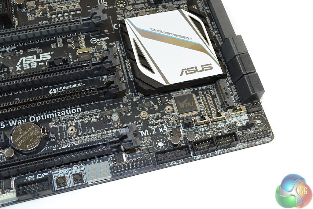
Asus’ smart M.2 Socket 3 connector positioning allows support for drives from 42 to 110mm in length. Getting its lanes directly from an LGA 2011-3 CPU, the port is only useable with PCIe-fed M.2 SSDs and does not support the SATA-based alternatives. I do not see that as an issue because the only real benefit for M.2 SATA SSDs is their small size in a confined (not ATX) chassis.
The M.2 connection does not steal chipset-fed lanes from the SATA Express port hence both can be used simultaneously. That also means CPU lanes are stolen from graphics cards even when a PCIe 2.0 x2 M.2 device (such as Plextor’s popular M6e) is used.
Just below the M.2 connector are switches which control the XMP, EPU, and TPU modes. This is also where the header to enable greater voltage levels is found.
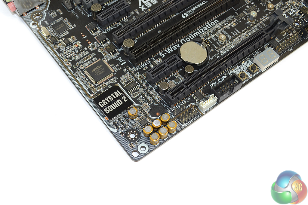
Asus’ Crystal Sound 2 audio system is based around the popular Realtek ALC1150 codec. Nichicon capacitors and EMI protection methods are used to optimise signal transfers to the front panel and rear IO connections.
A dedicated audio amplifier is used to drive high impedance headphones.
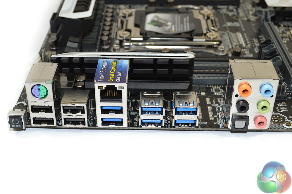
All but one of the rear IO USB 3.0 ports is delivered through ASMedia controllers. Three are deployed by splitting a single connection from the X99 chipset into three downstream ports, using ASMedia’s ASM1074 hub controller. Another two are provided by means of the PCIe 2.0 x2-fed ASM1042AE host chipset. The remaining port comes directly from the X99 chipset.
An Intel I218-V chipset is used to provide Gigabit LAN. Asus’ Turbo LAN software allows for NIC management in a similar fashion to that used by Killer’s competing chipsets.
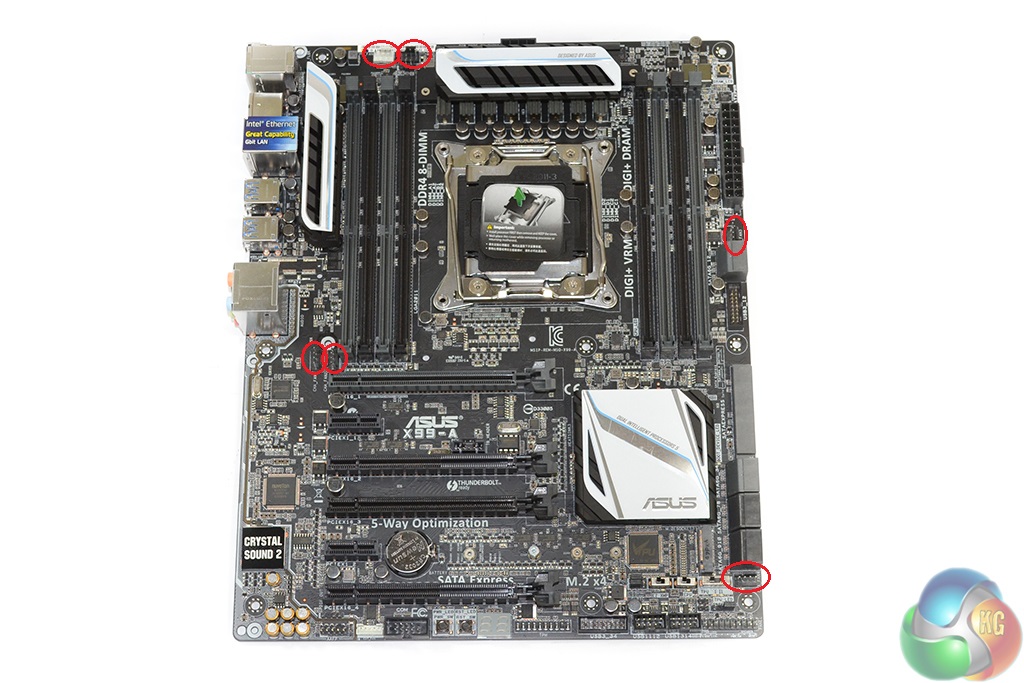
Asus’ distribution of the board’s six 4-pin fan headers is excellent. There are two CPU headers and a further two close to the CPU socket. This is ideal for AIO watercooler users as three fan headers are usually necessary.
The remaining two headers are well positioned for powering front or side panel fans. Nuvoton's NCT6791D chipset handles the fan control duties.

Luke, fantastic review. I am interested in two things.
Firstly, is the M.2 slot physically blocked by a second graphics card. For example, 2x4GB EVGA GTX 980? This card extends the whole width of this motherboard and I suspect the second card would occupy the third PCIe slot (PCIEX16_3 on the schematic). Due to the thickness of the card, I am worried that the M.2 slot is obscured.
Secondly, what benefit would I or other readers experience in your opinion by upgrading to the x99 Deluxe motherboard given the following components:
> Intel Core i7 5960X Haswell-E 8 Core
> 2x 4GB EVGA GTX 980
> 8x8GB Corsair DDR4 Vengeance
> 250GB Samsung 840 EVO Basic SSD SATA III
Thanks for your thoughts.