

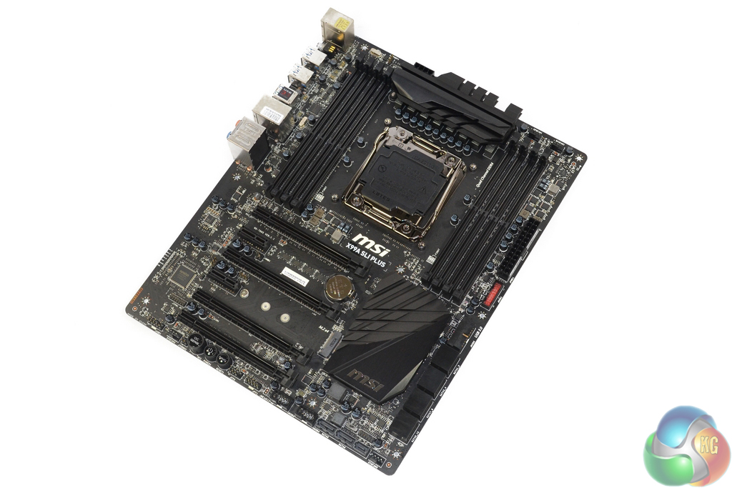
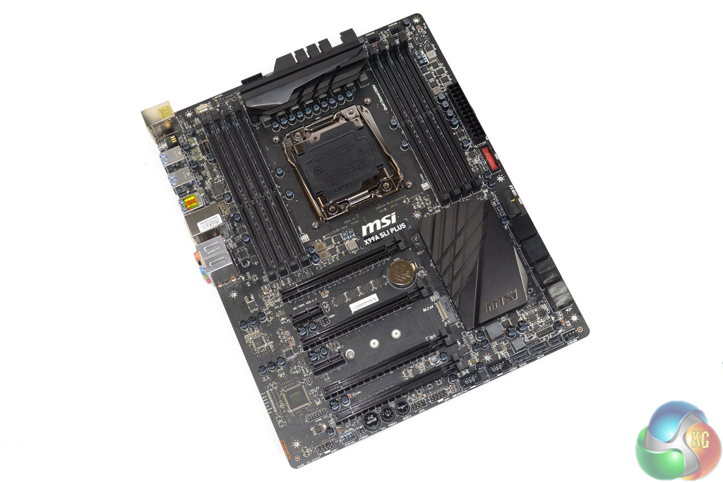
Styling for the MSI X99A SLI Plus motherboard is a positive to users who like to colour match their system's components. The dark black colour scheme that is maintained throughout should make component matching a simple procedure.
There are no awkward blue or red patches, and this is likely to appeal to many users who want to simply customise their system's styling.
Eagle-eyed users may spot the layout similarities between the X99A SLI Plus and the X99S MPower and X99S Gaming 7 motherboards that we reviewed last year.
MSI seems to be cutting engineering design costs by reusing the same PCB configuration but changing certain feature to acclimatise each board for their target audiences. This is one of the methods that allows MSI to hit such an aggressive price point for a feature-rich motherboard.
The Gaming 7 variant, for example, ships with a Killer NIC and ‘gaming-orientated' red and black colour scheme. The X99S MPower, on the other hand, features additional onboard buttons and a stronger power delivery system in order to entice overclocking enthusiasts.

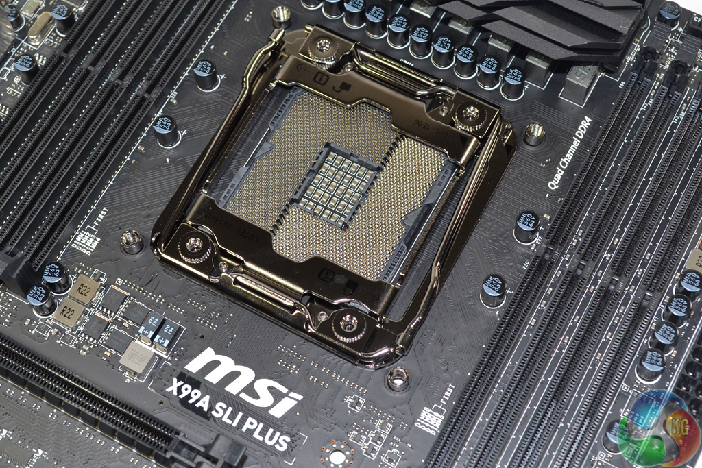
Four DIMM banks either side of the sizeable LGA 2011-3 CPU socket provide capacity for up to 128GB of DDR4 memory. MSI quotes memory frequency support of 3333MHz, although that will depend upon the strength of a CPU's IMC and the stability of the BIOS revision.
Novice users may have trouble configuring quad-channel memory correctly due to all DIMM slots using the same shade of black. With that said, it is unlikely that novices who are inexperienced with correct memory installation will be building with an X99 motherboard.
MSI makes uses of the standard LGA 2011-3 CPU socket, not the ‘OC Socket' design that features a higher number of pins in order to improve overclocking capacity (especially for the CPU cache speed).
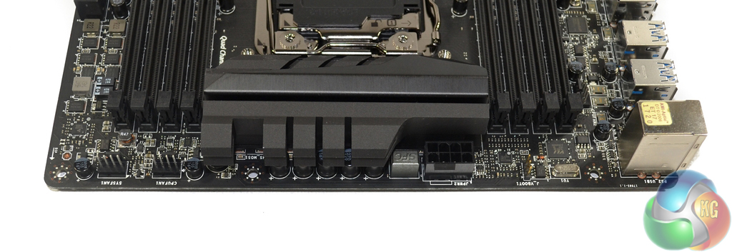
Two 4-pin fan headers are found along the motherboard’s top edge, one of which is allocated CPU duties, with the other running from the system fan channel. The other 4-pin CPU fan header is found between the DIMM bank and rear IO shield. MSI nestles the 8-pin power connector close to the primary MOSFET heatsink.
Compared to the closely related X99S MPower and X99S Gaming 7 motherboards, MSI ditches the two-digit debug LED for the X99A SLI Plus. Even accounting for the low cost, I am disappointed to see the two-digit debug LED omitted as it is a cheap and convenient troubleshooting tool.
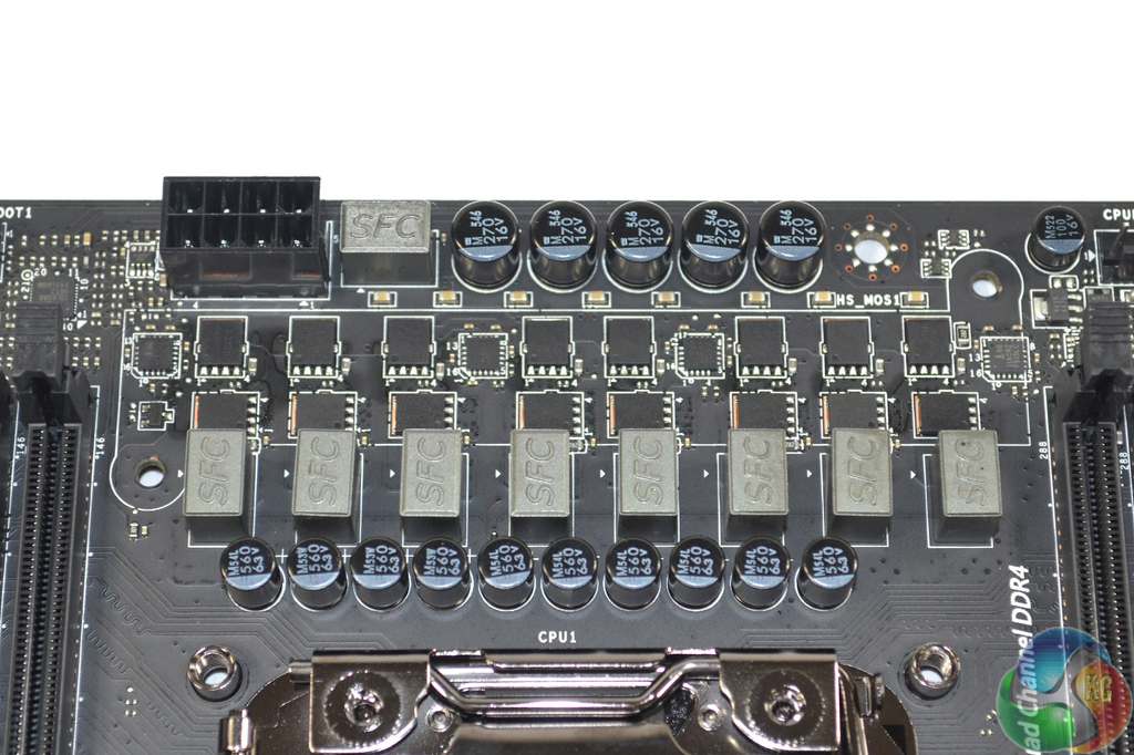
Another area where MSI is able to shave a small amount of cost out of the motherboard is the power delivery system. Instead of using popular co-packaged MOSFET solutions from the likes of Fairchild or International Rectifiers, the company opts for ON Semiconductor high- and low-side MOSFETs.
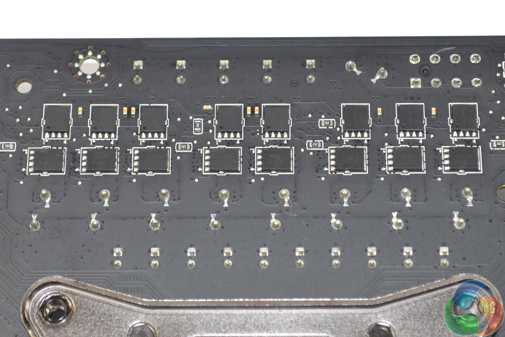
Split evenly between the front and rear side of the motherboard are 16 ON Semiconductor NTMFS4C08N and a further 16 NTMFS4C05N high- and low-side MOSFETs. Eight of MSI's Super Ferrite Chokes (SFC) indicate that this is a true eight-phase design with additional power MOSFETs added into the mixture.
Overall power delivery system management is handled by the 6-phase Intersil ISL6388 PWM controller. Acting as phase doublers and MOSFET drivers are four of Intersil's ISL6611A (marked ‘11ACRZ‘) components. These four drivers work with the PWM controller to modulate the sixteen sets of power MOSFETs and allow them to act as eight physical phases.
A solid heatsink and thermal pad cool the front side MOSFETs and phase doublers, while a low-profile strip heatsink tends to the rear side components. Each of the two DIMM banks is driven by a single Powervation PV3203 controller and a two-phase system utilising the same ON Semiconductor NTMFS4C08N and NTMFS4C05N MOSFETs as those found in the CPU area.
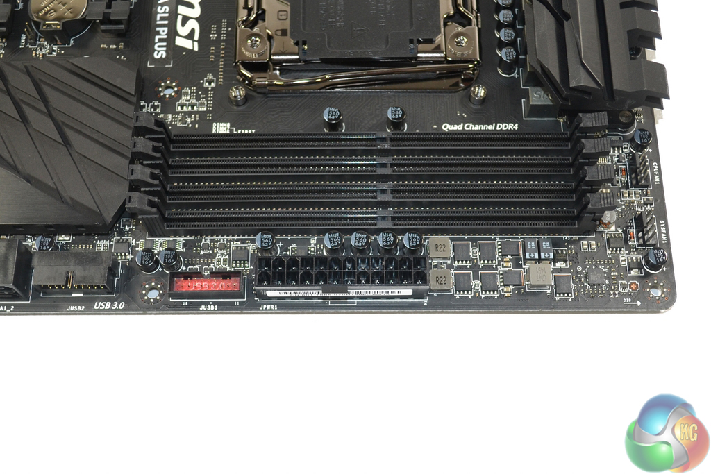
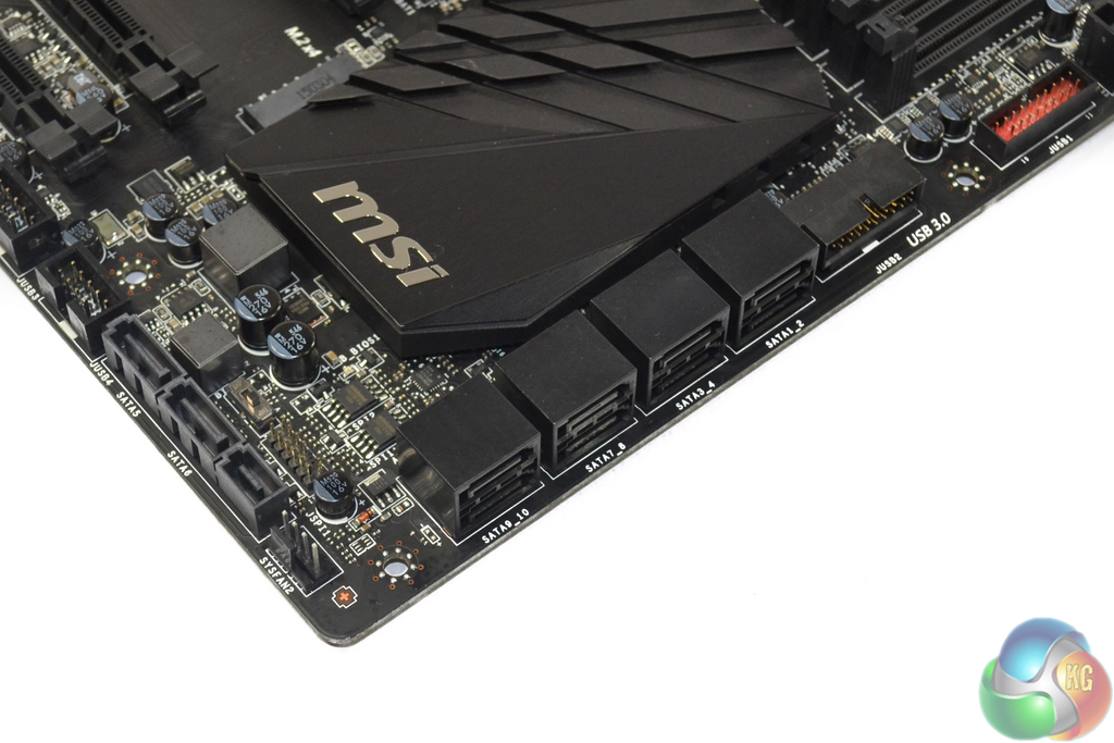
Close to the 24-pin power connector are the board's two chipset-driven USB 3.0 front panel headers. A pair of internal USB 3.0 headers is a smart move for a modern motherboard as some cases use four front panel USB 3.0 ports. MSI's chosen orientation of one pointing outwards and one sideways is smart as it leaves room for neat cable management in multiple usage scenarios.
The board features ten SATA 6Gbps ports, all of which stem from the X99 chipset. A single pair of these ports can be switched for a PCIe 2.0 x2 lane in order to provide the 10Gbps SATA-Express connection. Front panel USB 3.1 enclosures (as are supplied with some Z170 motherboards) are pretty much the only devices that make practical use of the 10Gbps SATA-Express connection.
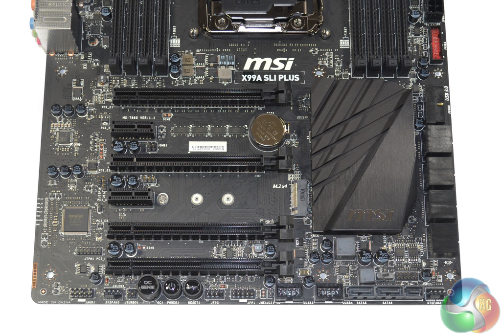
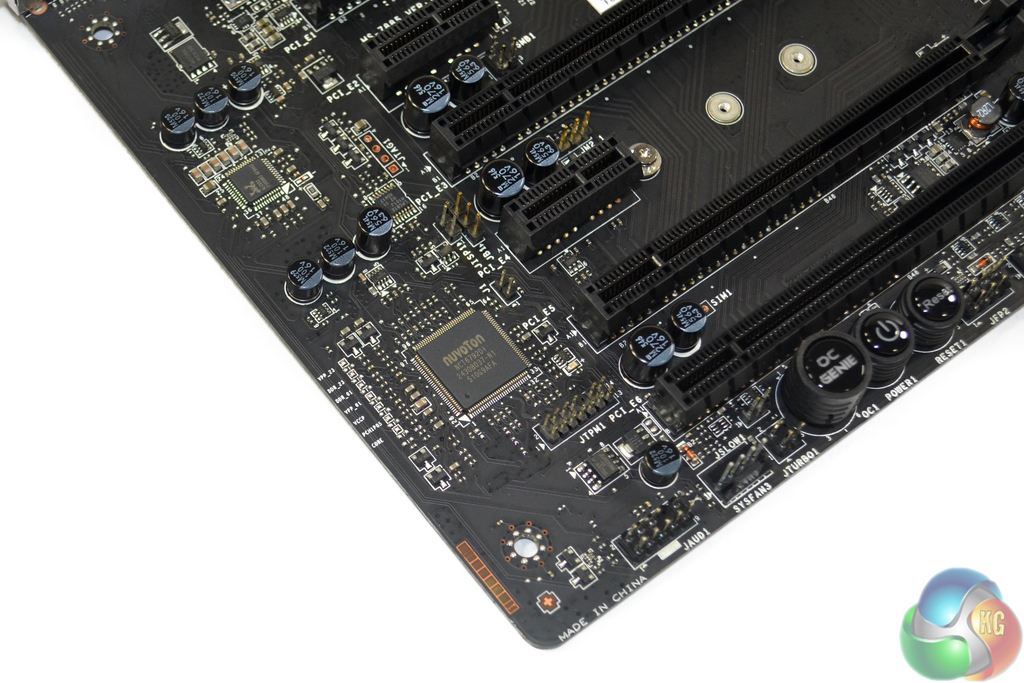
As was the case with the X99S MPower and X99S Gaming 7 that we previously reviewed, MSI's user manual creates confusion as to the ‘best‘ expansion slot arrangement.
Up to 3-way SLI/CrossFire is supported when using either 28-lane (5820K) or 40-lane (5930K, 5960X) processors. 4-way configurations with sufficient bandwidth are not possible (as also suggested by the slot spacing), although I do not see this as an issue for a ~£170 motherboard.
As with the Gaming 7 and MPower, the SLI Plus' PCIe connections for a 40-lane CPU are allocated as x16/x0/x0/x0 for a single card, x16/x16/x0/x0 for two cards, and x16/x16/x0/x8 for three cards. The one- and two-card configurations support PCIe 3.0 x4 for the M.2 connector, but three graphics cards will drop that link to PCIe 2.0 x2. That’s a big bandwidth hit on the storage front; we would have preferred MSI to drop one of the three cards to x8 link speed and maintain the PCIe 3.0 x4 connection for a high-speed M.2 drive (a workaround highlighted below can achieve that).
Using a 28-lane chip, a single card runs at x16, but two operate at x16/x8/x0/x0, which is a terrible spacing arrangement for graphics card cooling. Three cards all get eight PCIe lanes each. PCIe 3.0 x4 for the M.2 connector is preserved throughout.
In order to overcome the cooling worries of using back-to-back graphics cards, the first and third full-length PCIe slots can be used when running a 5820K CPU (as we saw OCUK apply here). A similar graphics card placement workaround can be used to run three graphics cards alongside a PCIe 3.0 x4 M.2 SSD when using a 40-lane CPU (don't use the bottom full-length PCIe slot).
Firstly, the two PCIe 3.0 x16 slots should have a cooling space between them – i.e. they should be the first and third full-length slots on this board. Secondly, MSI should update the manual to make the slot placement flexibility far clearer for multi-GPU users who are happy to sacrifice their PCIe 3.0 x16 link in favour of an x8 connection and better cooling.
Nestled between the PCIe expansion slots is the 32Gbps PCIe 3.0 x4 Turbo M.2 connector. The slot can also operate with PCIe 2.0 x2 and SATA 6Gbps M.2 SSDs, but with its 32Gbps bandwidth capacity it is ideal for ultra-fast SSDs such as Samsung's 950 Pro.
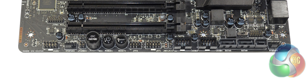
The standard array of front panel headers are found along the board's bottom edge. MSI places the onboard power, reset, and OC Genie buttons in this location allowing a potential interference issue to be caused by a graphics card in the lower slots. The SATA-Express connector will also suffer from that interference problem.
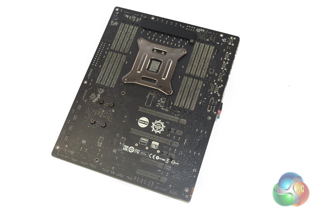
It is good to see MSI using dual BIOS chips for redundancy as well as a switch to manually toggle between them.
Audio for the X99A SLI Plus is based around Realtek's ALC892 codec. While the ALC892 codec is old by comparison to the popular ALC1150 alternative that is more common on today's mid-range and high-end boards, age doesn't necessarily translate into inferior performance.
A strip of voltage check points are situated close to the Nuvoton NCT6792D+ monitoring chipset in a very inconvenient location. Positioning the check points closer to the board's upper-right corner would have been beneficial to users who remove their side panel to quickly check the system voltages with a multimeter.
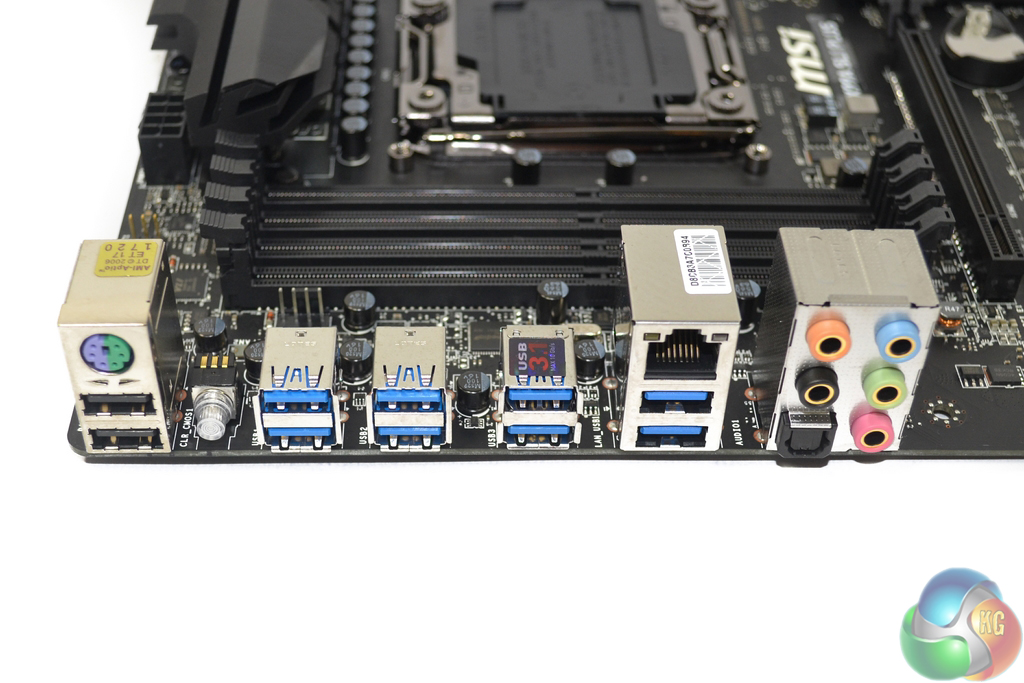
A PS/2 keyboard/mouse connection and two USB 2.0 ports serve solid legacy functionality which is ideal for troubleshooting. The rear panel clear CMOS button is an addition that is worthy of credit, as is MSI's inclusion of a blue LED that makes locating it more straightforward.
The four USB 3.0 ports furthest left are provided by a VIA VL805 4-port host controller. Given the chipset's single 5Gbps PCIe 2.0 lane input, it is safe to say that these ports are likely to show poor speed performance if more than one is used. The pair of USB 3.0 ports beneath the Intel I218V Gigabit Ethernet connection are both provided from the X99 chipset.
The pair of blue-coloured ports immediately to the left of the LAN connection are 10Gbps USB 3.1 Gen 2 Type-A ports provided by an ASMedia ASM1142 chipset.
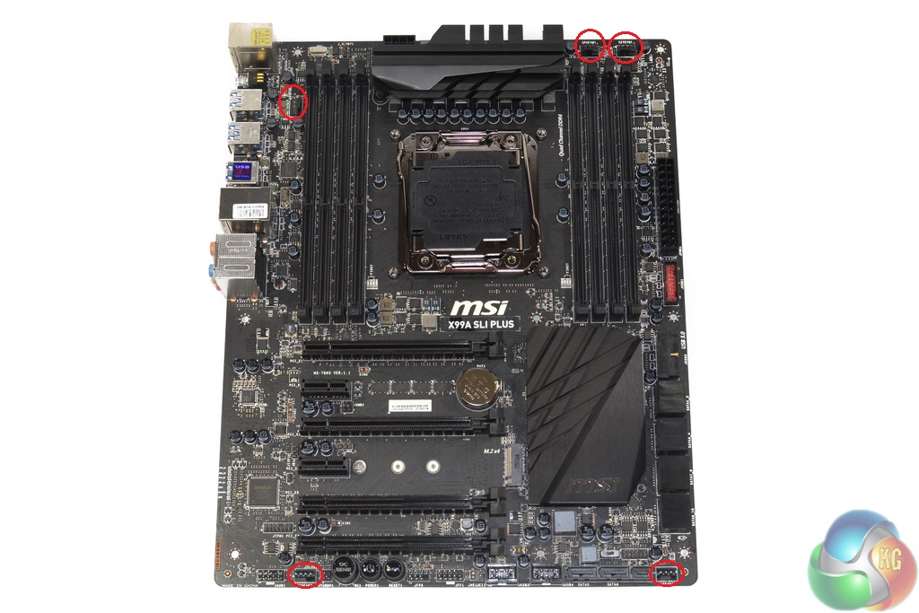
A somewhat meagre number of fans headers is spread around the board. Three of the five 4-pin headers are within direct reach of the CPU socket, two of which are allocated CPU fan duties. The remaining two found along the board's bottom edge are good for serving front and side panel chassis fans.
It is disappointing to see a header being removed from the typical location for serving a rear chassis fan mount – just above the uppermost PCIe expansion slot.
Nuvoton's NCT6792D+ chipset provides monitoring and fan control capability.

Wow, what a board! I’ve been eyeing this MSI motherboard for ages. It looks stunning and so cheap too. I think I’ll have to buy this come Black Friday!
I have S version of that board, the only difference is that this one has additional USB 3.1 controller. This board gave me a lot of problems to boot with G.Skill 8GB RAM sticks. It booted only with one stick and what was more frustrating it could boot only from the second BIOS. After I did BIOS update all started booting fine with all slots occupied.