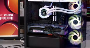

The styling of mini-ITX motherboards is always broadly similar given the limited space for customisation after placing non-negotiable elements like the CPU socket, PCIe lane and memory slots. Supermicro's SuperO C9Z390-CG-IW is particularly plain as there's no significant styling on the VRM heatsinks, neither on the chipset heatsink. That's no bad thing as there aren't many mini-ITX cases with large display windows. Even in a windowed-case this motherboard does fine with its mostly-black aesthetic and onboard RGB lighting.
Onboard RGB lighting is provided in a single zone along the edge of the motherboard where the 24-pin connector resides. These LEDs are pleasingly bright and there's an optional 12V G R B connection for anyone wishing to add more RGB lighting flair.
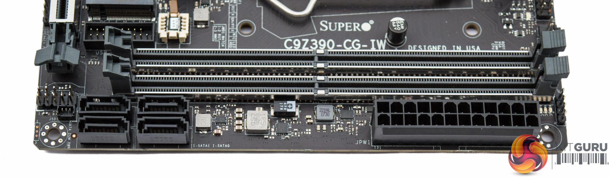
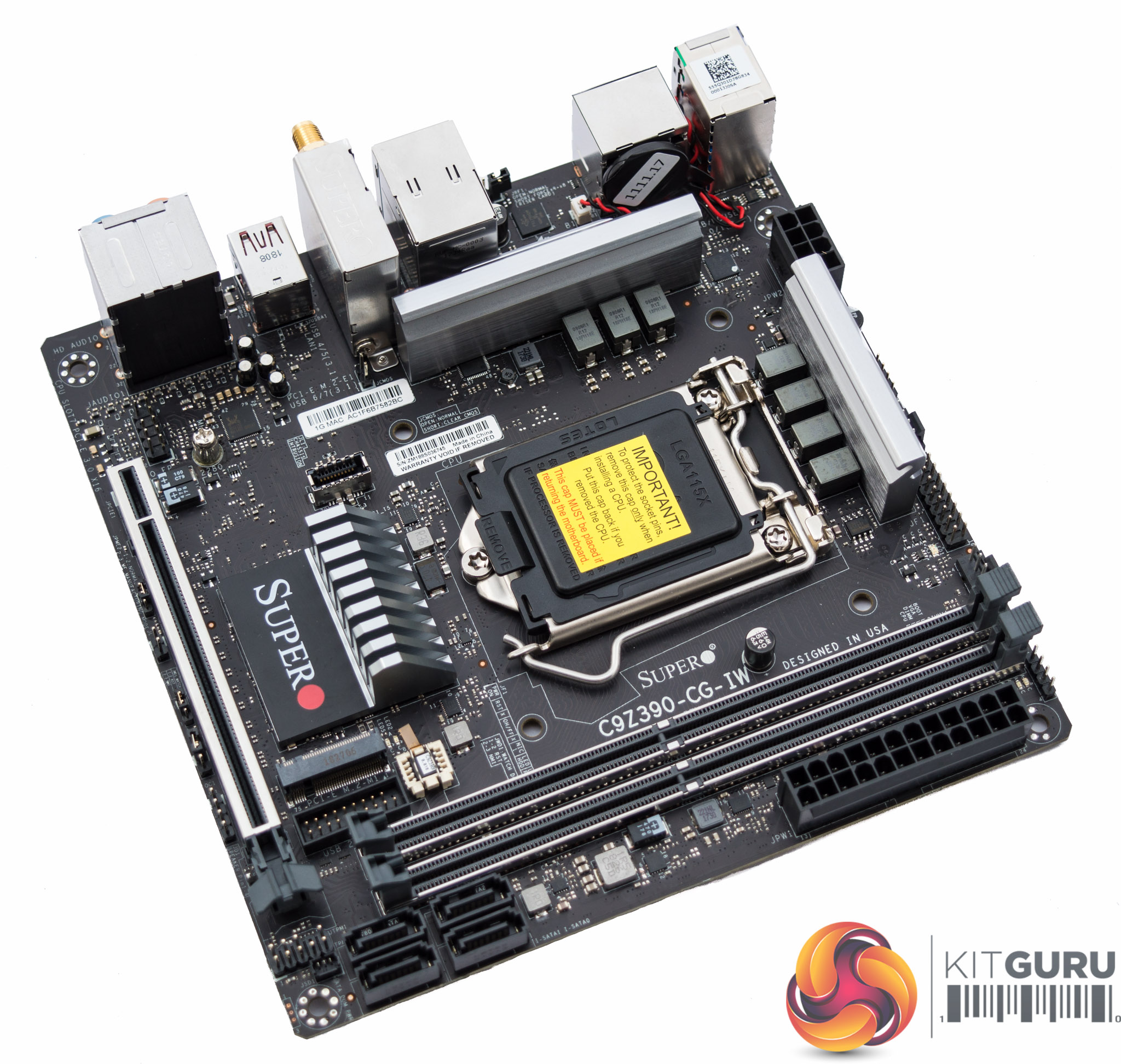
Supermicro implements only four of the six available SATA ports, presumably due to space limitations. This isn't necessarily a bad thing though as it means both M.2 slots can operate in SATA mode without deactivating any standard SATA ports, this way all six SATA port “lanes” can actually be used concurrently.
Hidden towards the motherboard 24pin is a debug LED section with four LEDs (BOOT/CPU/DIMM/VGA) for troubleshooting. There's also a power-on LED near the CPU socket and M.2 activity LEDs for the primary M.2 slot mounted on the top side of the motherboard.
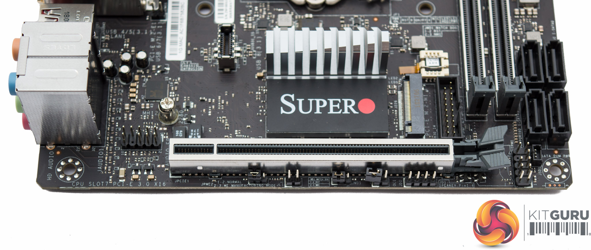
The single PCIe 3.0 16x lane features shielding for additional support. Beside the PCIe lane is the first of two M.2 slots, both of which have no cooling solution.
Around that same M.2 slot are the only two USB headers – one type USB 3.1 supplying a single USB 3.1 port and the other type USB 3.0 supplying up to two USB 3.0 ports.
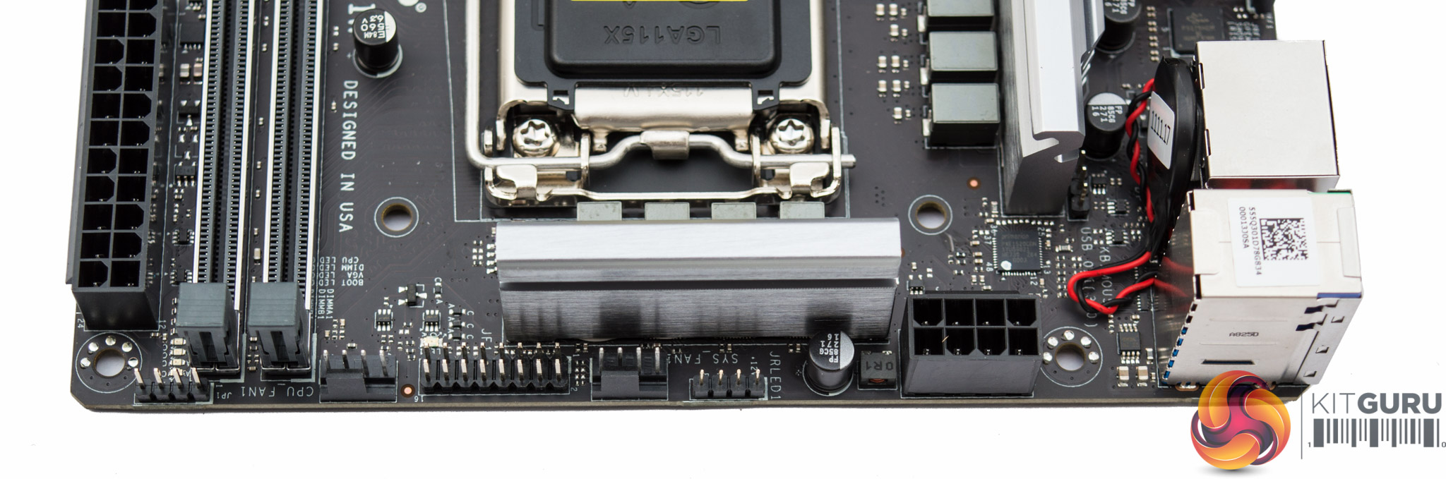
Around the CPU socket are the only two fan headers, marked CPU and System, as well as the single RGB LED connection. Power is drawn into the CPU VRM through an 8pin EPS connection.
Note the CMOS battery is mounted vertically to save space, a common practice on mini-ITX motherboards. However, in this instance there is no clear CMOS button to go with it meaning a failed overclock has to be recovered by unplugging the fiddly CMOS battery cable – which is less than ideal.
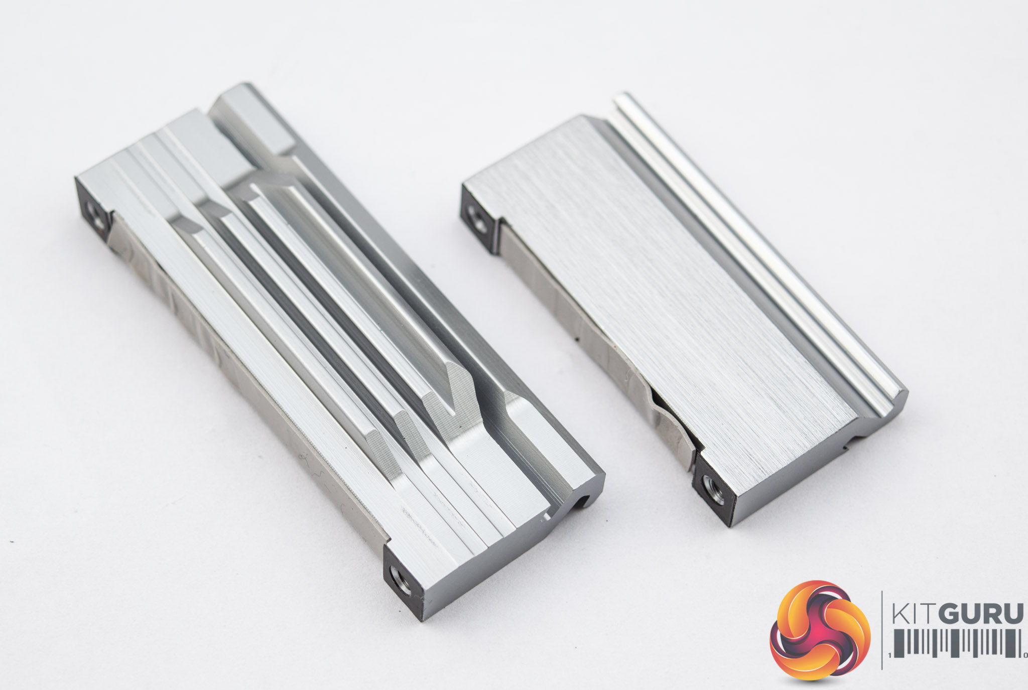
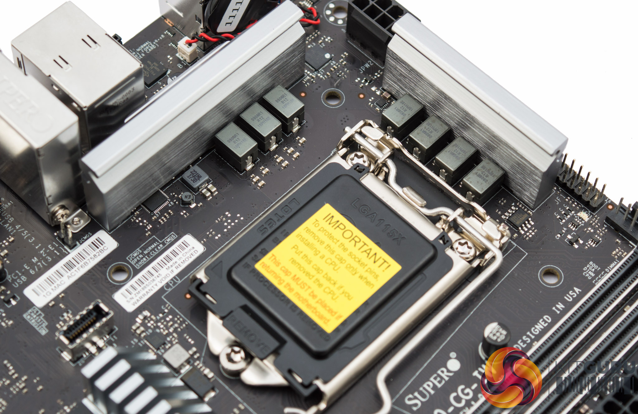
Unlike on Supermicro's Z370 model, there are two CPU VRM heatsinks for both MOSFET areas. On this motherboard Supermicro has split the VRM into 4 and 3, even though it operates as 5+2, which means both heatsinks cool the VCore VRM. This is important as the “+2” phases for the VCC GT (iGPU) do not get a great deal of use so having the heatsink also cooling part of the VCore makes a lot of sense, even if it's only 1 VCore phase.
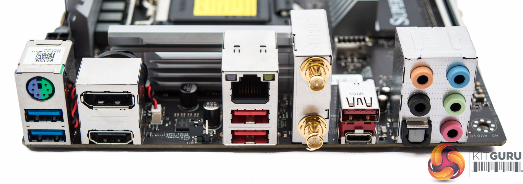
The rear I/O is well balanced and includes the following ports:
- 1 x PS/2 Keyboard/Mouse Combo
- 2 x USB 3.0 5Gbps (Blue)
- 3 x USB 3.1 10Gbps (Red)
- 1 x USB 3.1 10Gbps Type-C
- 1 x DisplayPort 1.2
- 1 x HDMI 2.0
- 2 x WiFi/Bluetooth Antennae
- 5 x Analogue Audio Jacks
- 1 x S/PDIF Optical Audio
- 1 x RJ45 Gigabit LAN
There is a bit of space in the rear I/O, where it would be nice to see a clear CMOS button.
Supermicro has integrated a CNVi WiFi and Bluetooth combination module into the rear I/O for users looking for wireless connectivity.
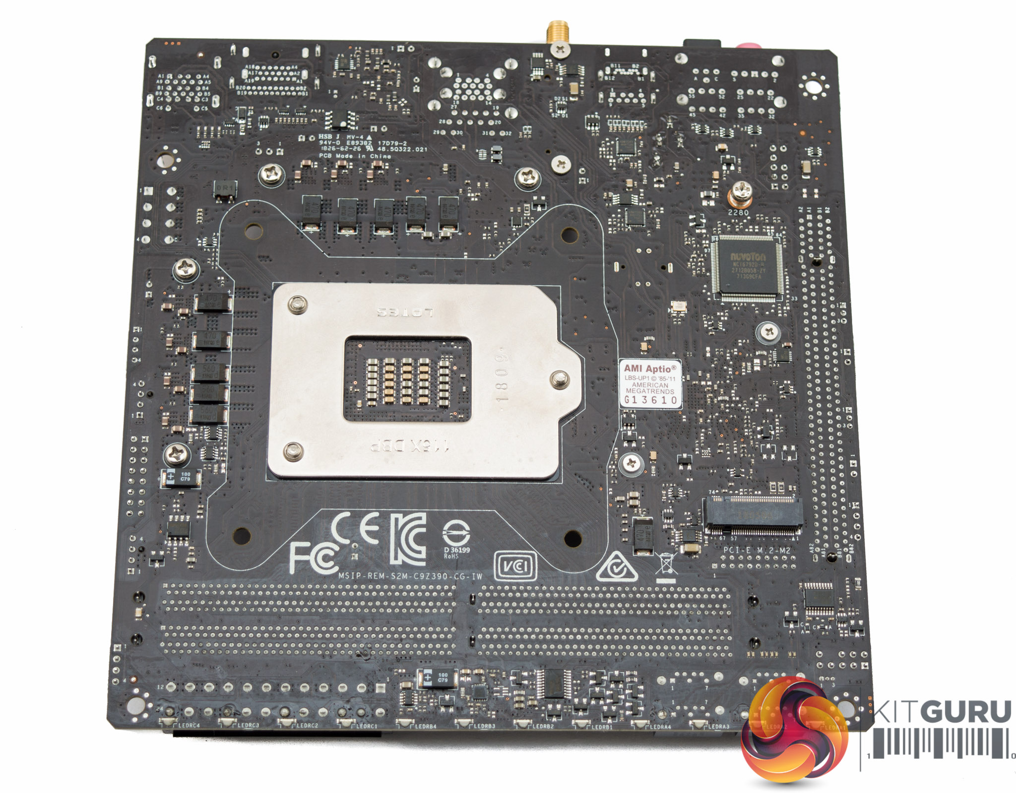
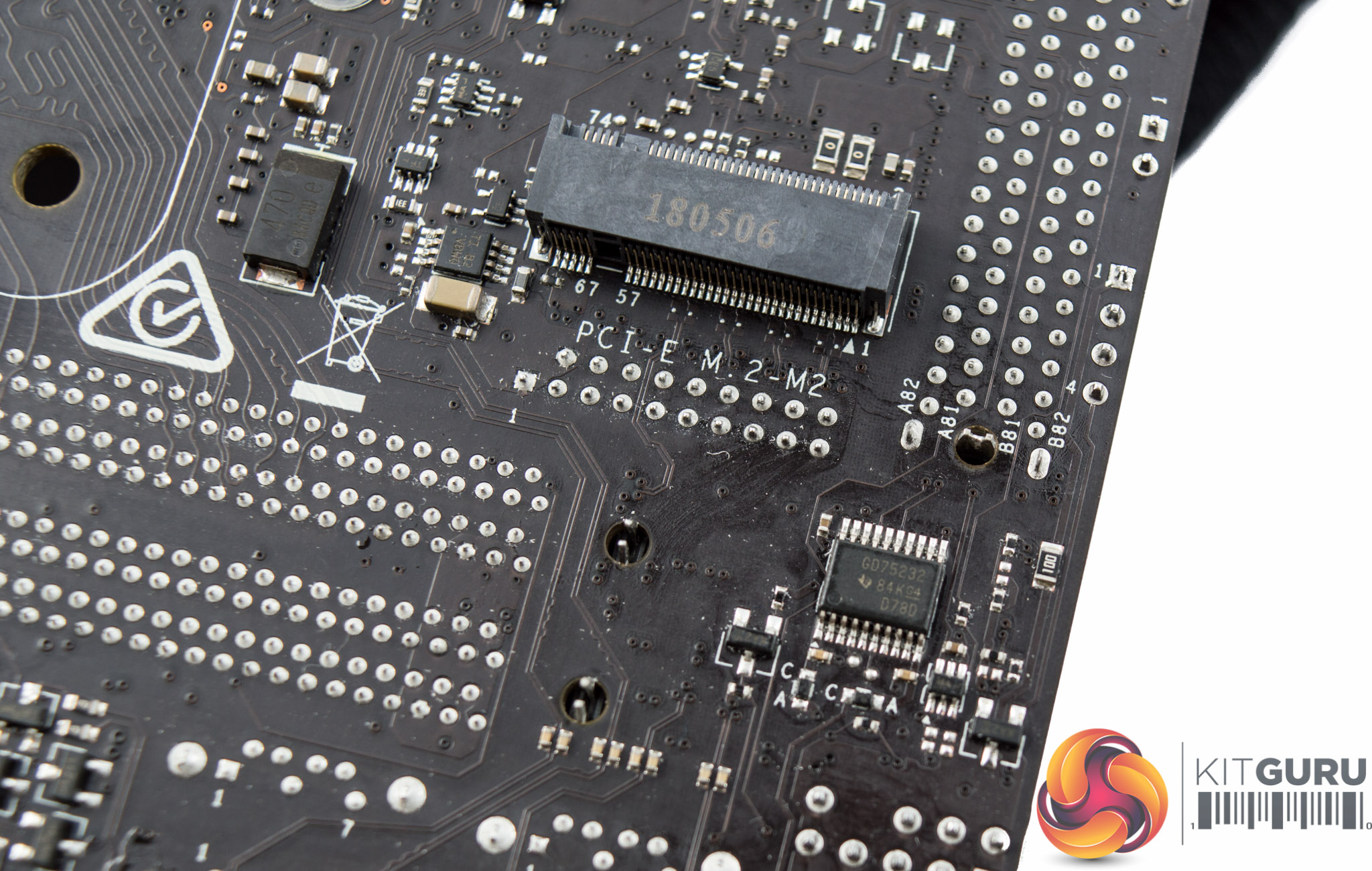
Underneath the motherboard is the second M.2 slot, which supports the same PCIe 3.0 X4 and SATA III modes as the M.2 slot above. There's also a number of cross-head screws for easy maintenance as well as a number of additional ICs and components that help with elements of power delivery and connectivity.
A Texas Instruments GD75232 chip sits underneath the header marked UTPM1, this chip is responsible for RS232 and UART communications.
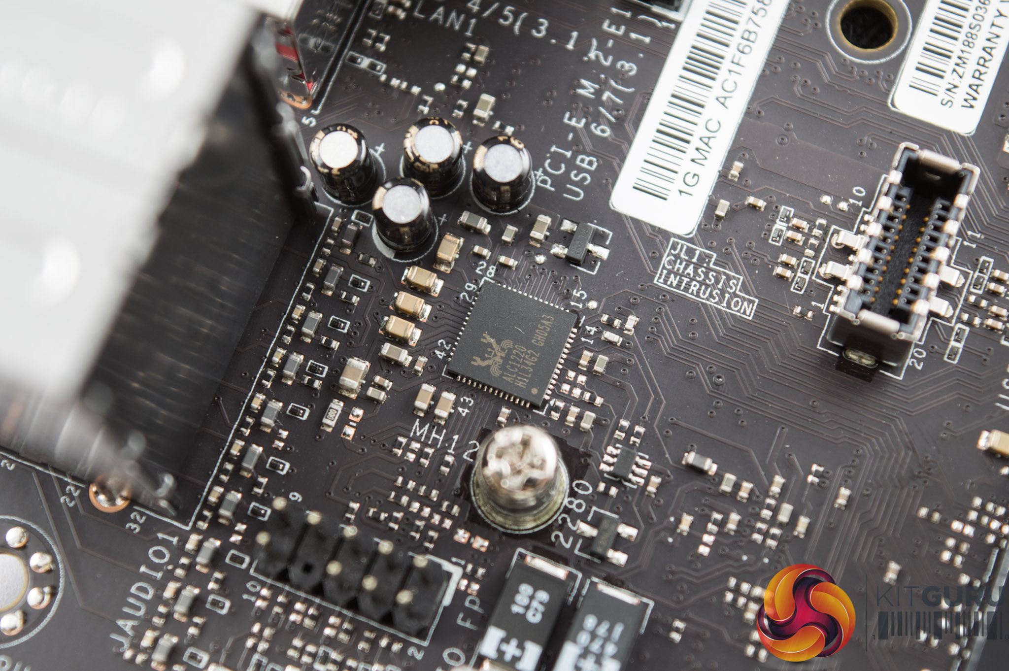
An unshielded Realtek ALC1220 codec provides the audio, it has four audio capacitors with it and is not on an isolated PCB.
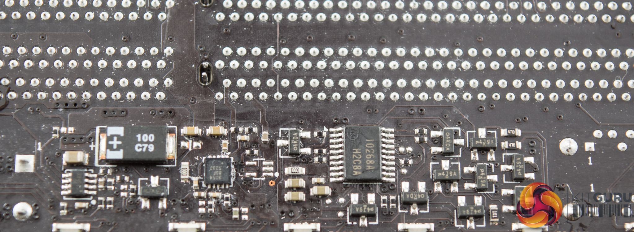
A Renesas 10268ASP microcontroller underneath the memory lanes, near the LEDs, and likely provides the control functionality for the onboard RGBs.
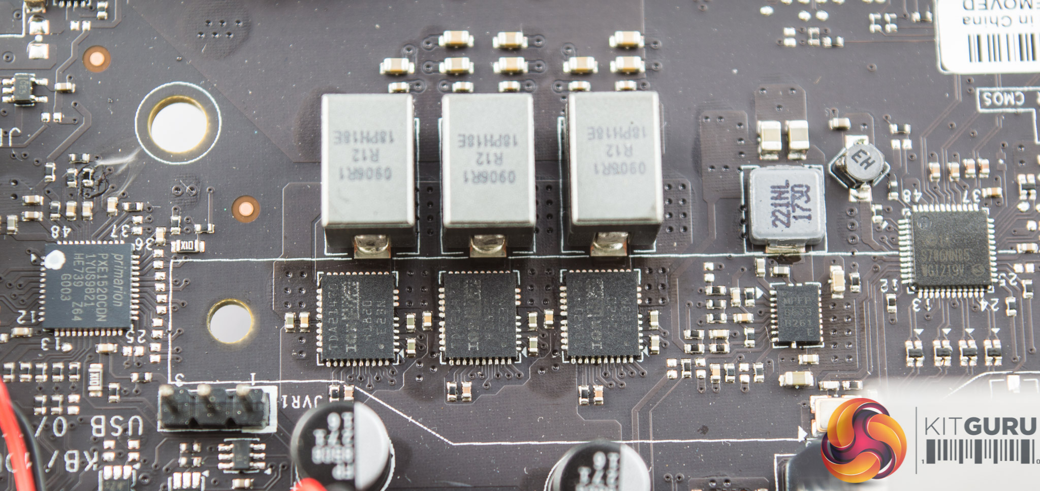
The CPU VRM is provided by the Infineon Primarion PX1520CDN. There's no easily accessible online datasheet for this controller but it is touted by various component resellers as being an “up to 5+2 phase” VRM controller.
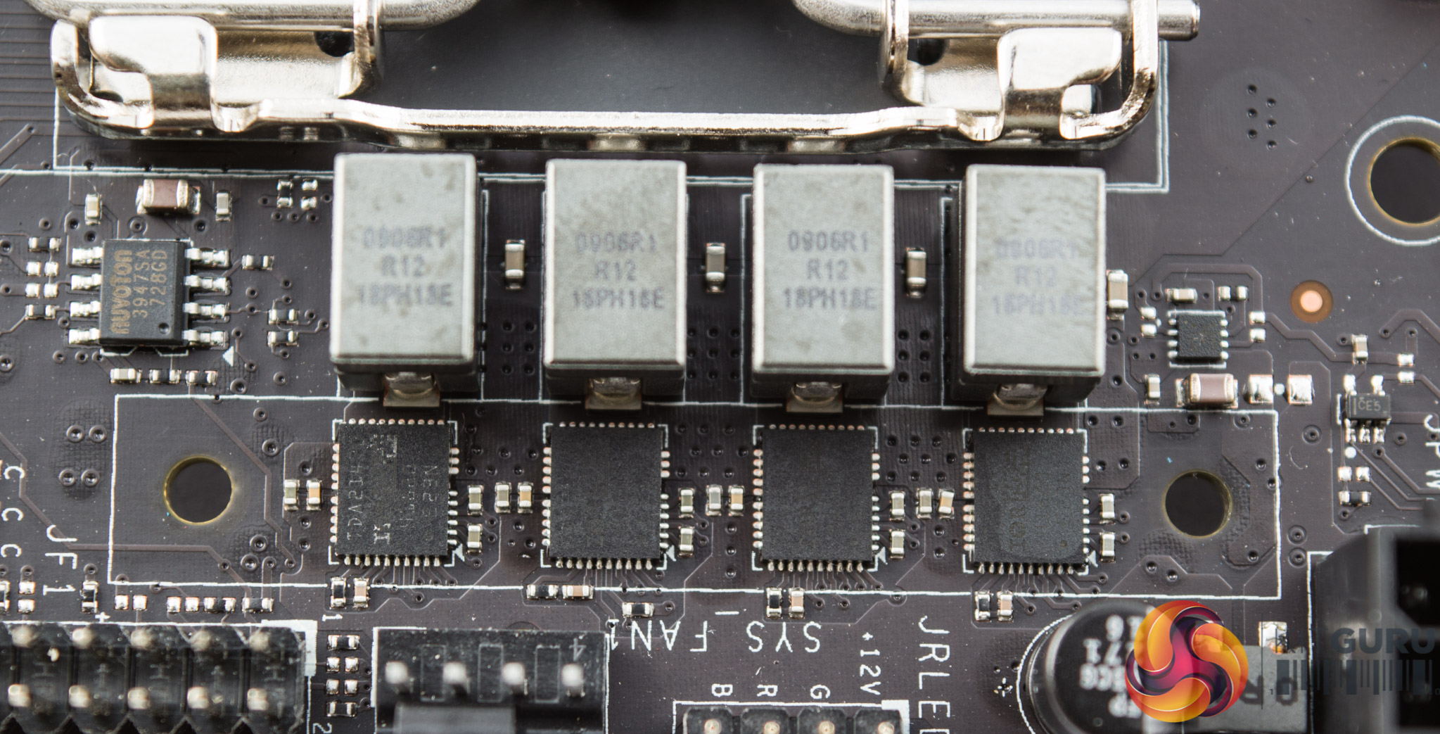
It appears then to be a 5+2 phase configuration, VCore + iGPU (VCCGT), spread into 4+3 blocks so that both VRM heatsinks cool the CPU VRM.
The MOSFETs used are Infineon TDA21470, which combine the high- and low-side, and are up to 94% efficient according to the datasheet.
There are some additional MOSFETs and ICs around the CPU socket that could be responsible for the VCCSA and VCCIO. Alongside the block of 3 MOSFETs is a Monolithic Power MPQ8633B unit that is most likely stepping down a 12v supply to the VCCSA or VCCIO. There are another two MPQ8633B ICs around the chipset heatsink that could be doing something similar.
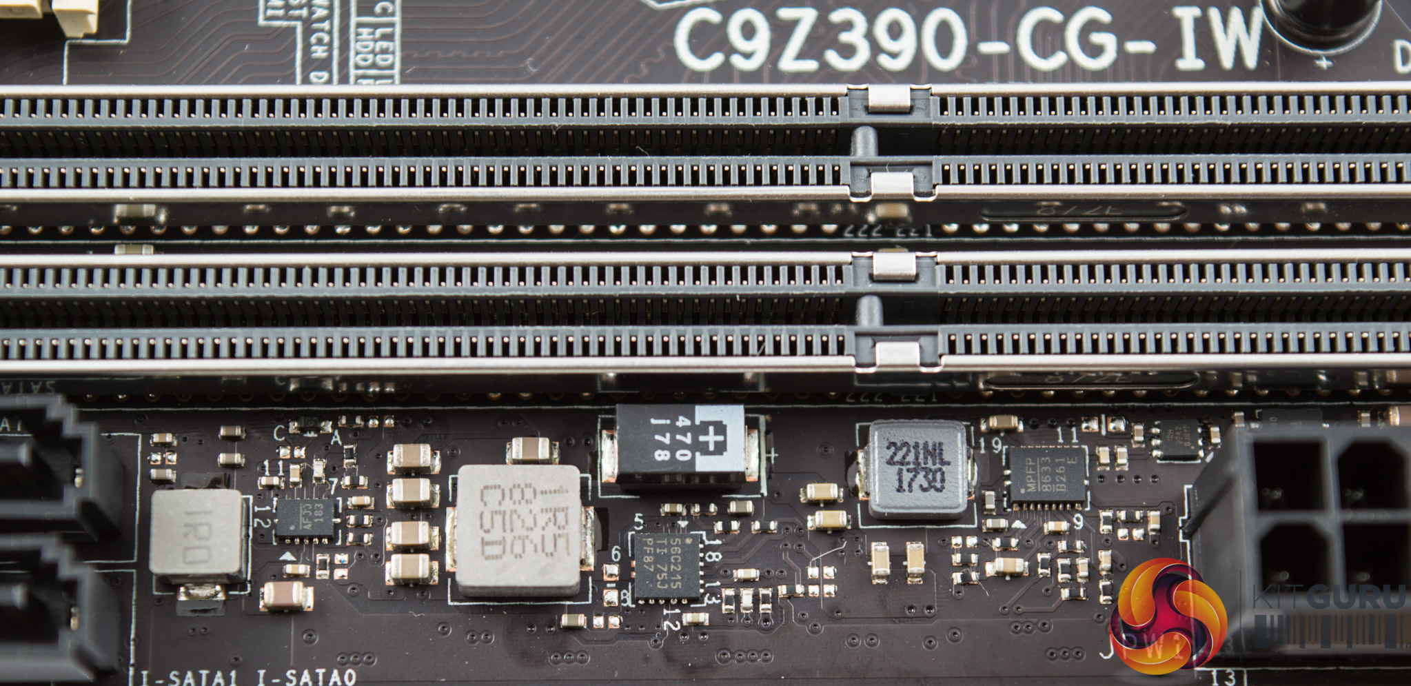
There's a Texas Instruments TPS56C215 step-down converter which likely takes direct 12v input and outputs to the required voltage range for the DRAM – somewhere between 1.1 and 1.5v.
The IC marked “MPFP 8633 B261 E” is yet another Monolithic Power MPQ8633B step-down converter, likely taking 12v input voltage and giving DRAM output voltage also.