

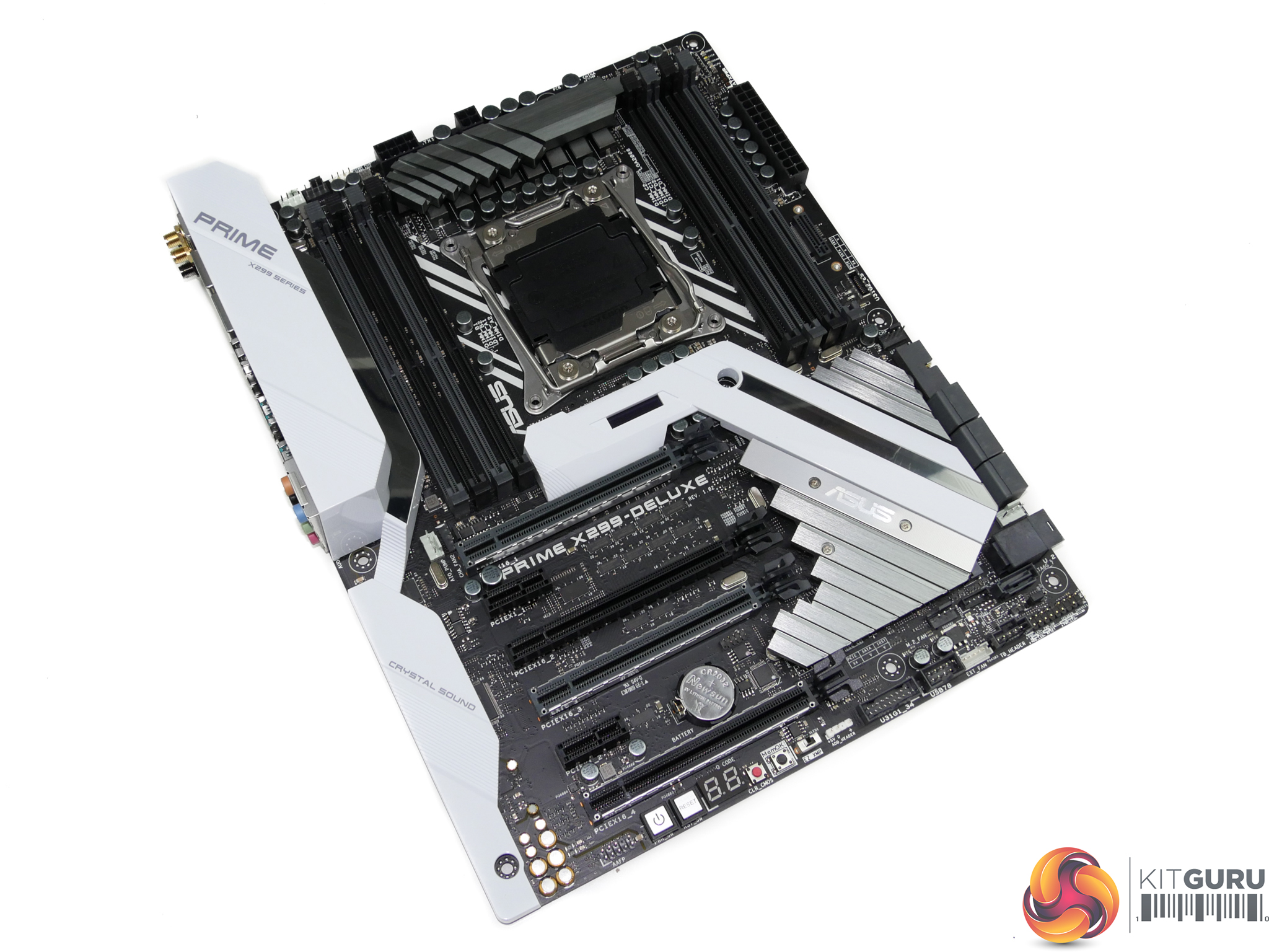
The ASUS Prime X299-Deluxe uses a primarily white, black, and grey colour scheme. Different shades of the three primary colours are spread across the ATX motherboard, with white seeing heavy uses on the rear IO and audio section cover.
Positioned in the centre of the motherboard is the LiveDash OLED display. This screen is used to display information such as the CPU temperature and voltage during usage. It’s a cool addition to the package but its positioning may cause viewability issues to users with large tower air coolers.
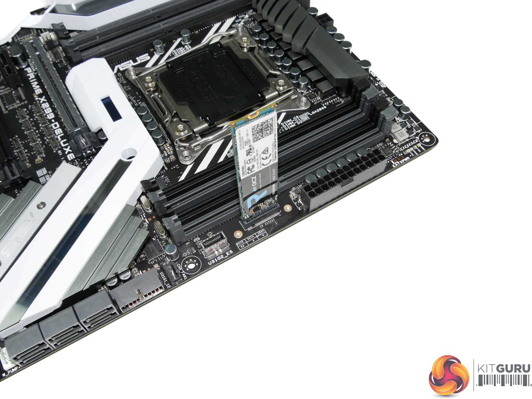
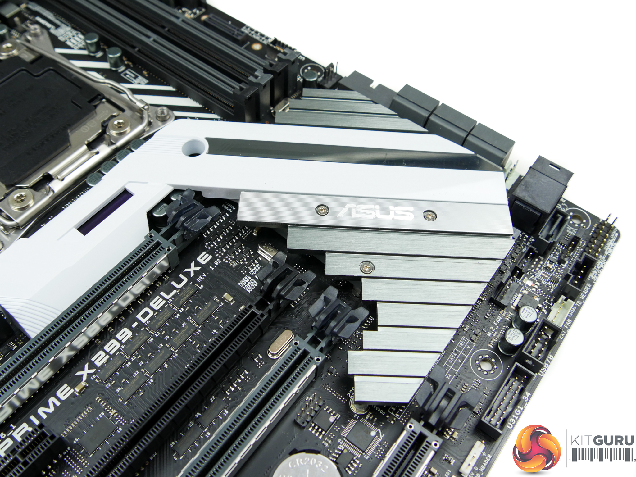
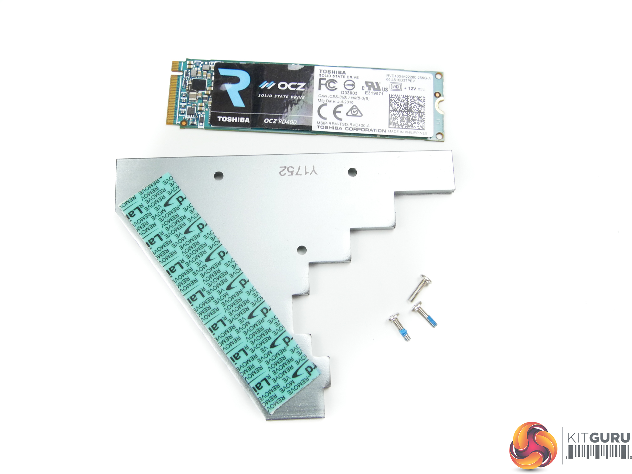
Positioned close to the 24-pin is one of the board’s two M.2 connectors. This PCIe 3.0 x4-only slot is mounted to allow for vertical orientation of an installed M.2 device. A support bracket and screws are included. Vertical mounting is good for putting the device in a direct airflow path, while also minimising the footprint taken up on the board PCB.
ASUS includes one of the new internal USB 3.1 Gen 2 10Gbps headers so that users can get 10Gbps front panel connectivity with future case designs. This connection is powered by an ASMedia ASM3142 USB 3.1 Gen 2 chipset operating in PCIe 3.0 x1 mode from the X299 chipset (and therefore limited to around 8Gbps maximum bandwidth). LEDs for the CPU, DRAM, VGA, and Boot provide basic troubleshooting assistance.

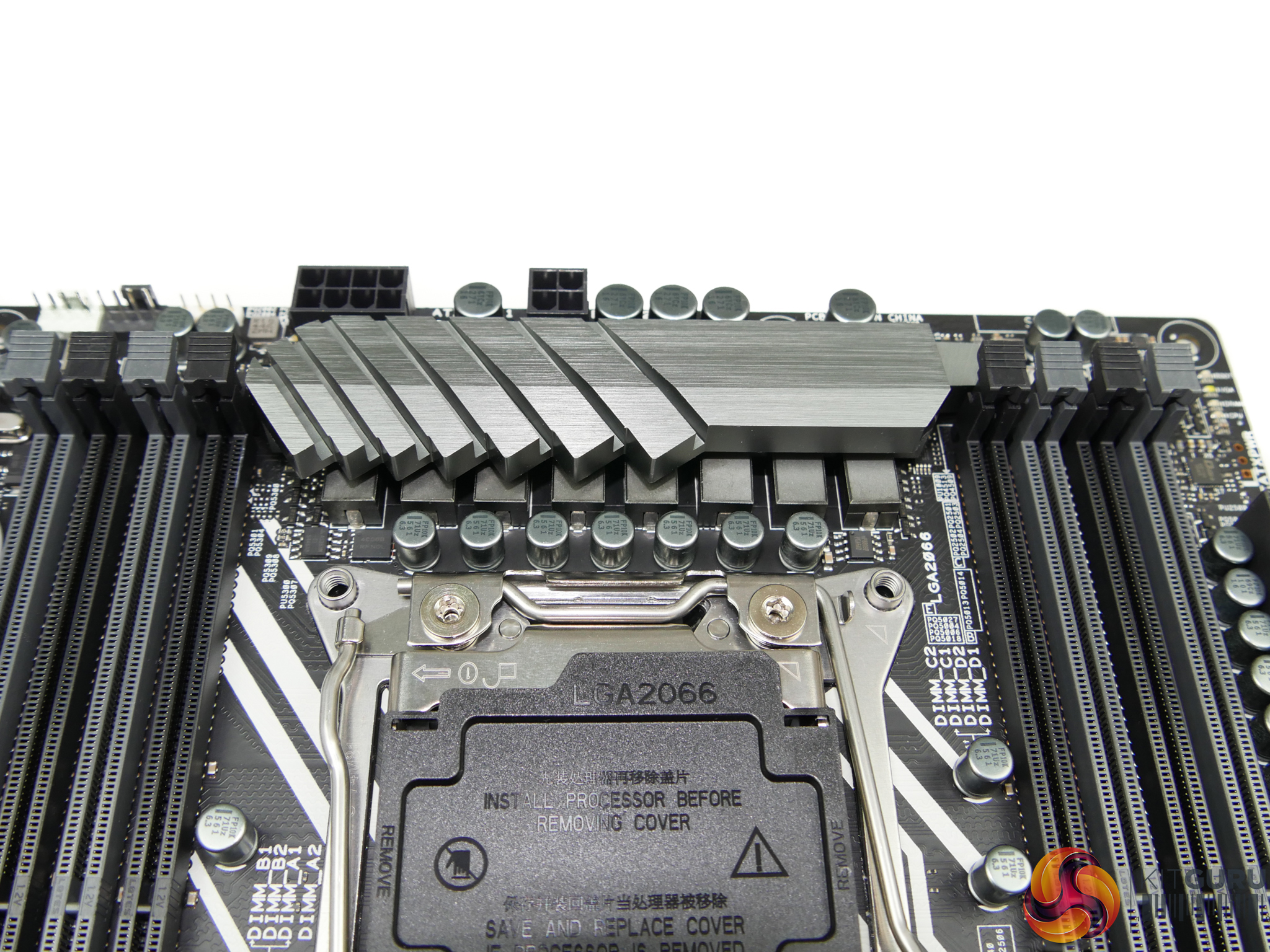
128GB of DDR4 can be installed alongside the LGA 2066 CPU. ASUS feeds the 8-phase CPU power delivery system with an 8-pin plus a 4-pin connector. This helps to allow the provision of more than 300W of continuous power when loading an overclocked high core count Skylake-X chip. Single 8-pin solutions may start to struggle when tasked with loading overclocked 12-18 core CPUs.
Digi+ VRM EPU ASP1103 PWM controllers drive the 2+2 phase DRAM power delivery system.
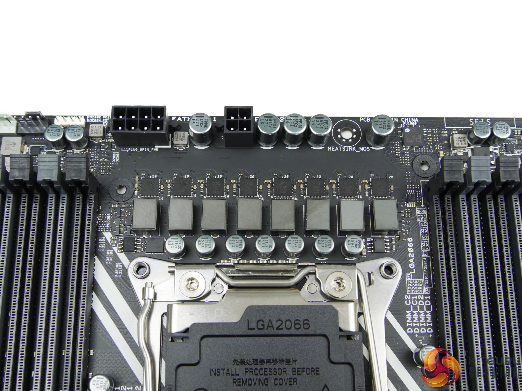
ASUS’ proficient power delivery system is built around the vendor’s ASUS-packaged Digi+ VRM EPU ASP14051 PWM controller. The system utilises eight International Rectifiers IR3555M MOSFET solutions.
These 60A-rated integrated PowIRstage offerings from International Rectifiers are widely regarded as being some of the best power delivery MOSFET solutions on the market. They are both electrically efficient and space efficient, with the latter point being important for the tight space constraints on X299 motherboards. We did, however, notice a little coil whine on our board sample.
ASUS MOSFET heatsink design is sub-par, as has been highlighted by der8auer’s popular videos on the topic of X299 VRM solutions. The small block of metal is clearly a form-over-function design as it looks appealing but does not feature design traits that are associated with an effective heatsink. This poor design may cause issues to more enthusiastic overclockers who push voltages to levels where the block’s cooling capacity is saturated and power delivery capability is limited accordingly.
For average users with non-delidded chips, however, the VRM cooling solution is likely to be adequate. Not proficient or particularly good – just adequate.
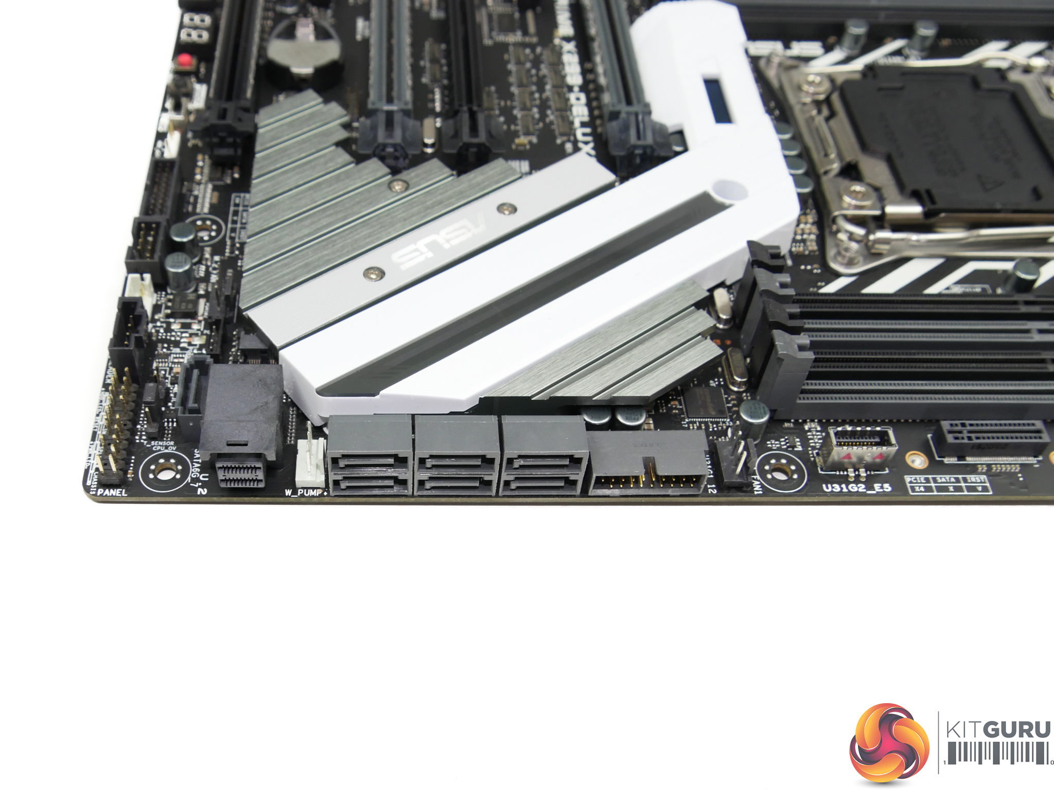
Seven SATA 6Gbps ports are mounted on the motherboard but not all of them can be used at any one time with certain partnering hardware. The bandwidth constrictions on Intel’s X299 platform means that SATA port 7 shares its bandwidth with the PCIEX1_2 slot, while SATA ports 5 and 6 share bandwidth with the PCIEX16_4 when using a 16- or 28-lane CPU.
One of the two internal USB 3.0 5Gbps headers is located next to the SATA ports, with a 32Gbps PCIe 3.0 x4 U.2 connector positioned on the other side. I like the inclusion of the U.2 connector as Intel’s SSD 750 in U.2 form is still a strong choice for workstation users who need significant high-speed, high-capacity solid-state storage. Unfortunately, the U.2 connector shares X299-fed bandwidth with the vertically-mounted M.2 slot, meaning that only one should be used at any time.
The VROC header is located close to the vertically-orientated SATA port.
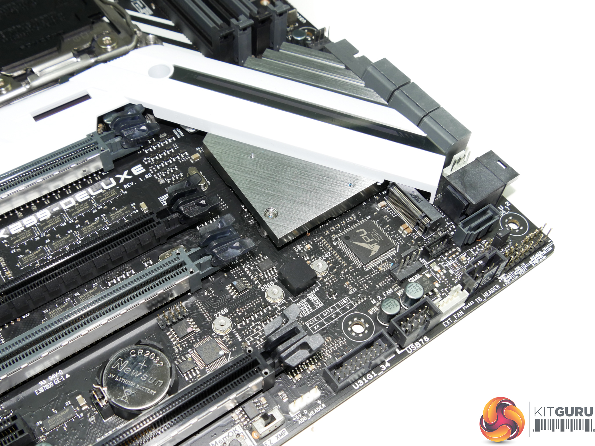
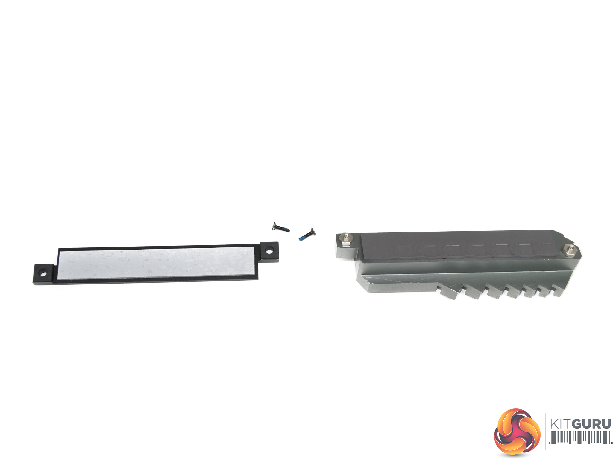
The board’s other X299-fed M.2 connector is accessed by removing a cooling plate connected to the chipset heatsink. This slot can take SSDs up to 80mm long and supports PCIe 3.0 x4 NVMe drives as well as SATA options. Intel Optane Memory is also supported.
ASUS’ cooling design for this slot is smart; a block of metal contacts the SSD via a thermal pad and dumps that heat onto the large chipset heatsink. This gives the system significant thermal mass (with respect to the power output from an M.2 SSD) that can be used to absorb thermal energy removed from the SSD. The design should be significantly better at dealing with thermal throttling on M.2 SSDs than a bare drive that struggles to receive airflow.
An added quirk of the thermal cover is that the M.2 SSD is hidden. That’s a negative for users who want to show off their shiny new Samsung 960 Pro but it’s a positive to those who want to hide the ugly green PCB on their Samsung SM961 SSD, for example.
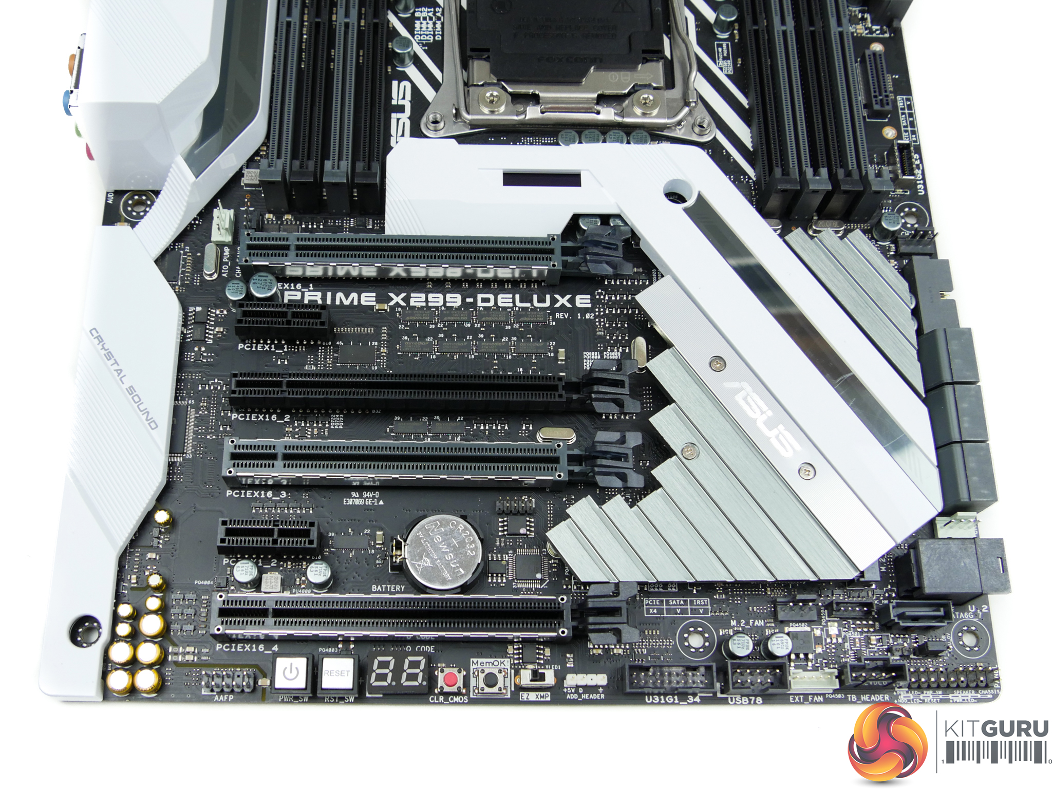
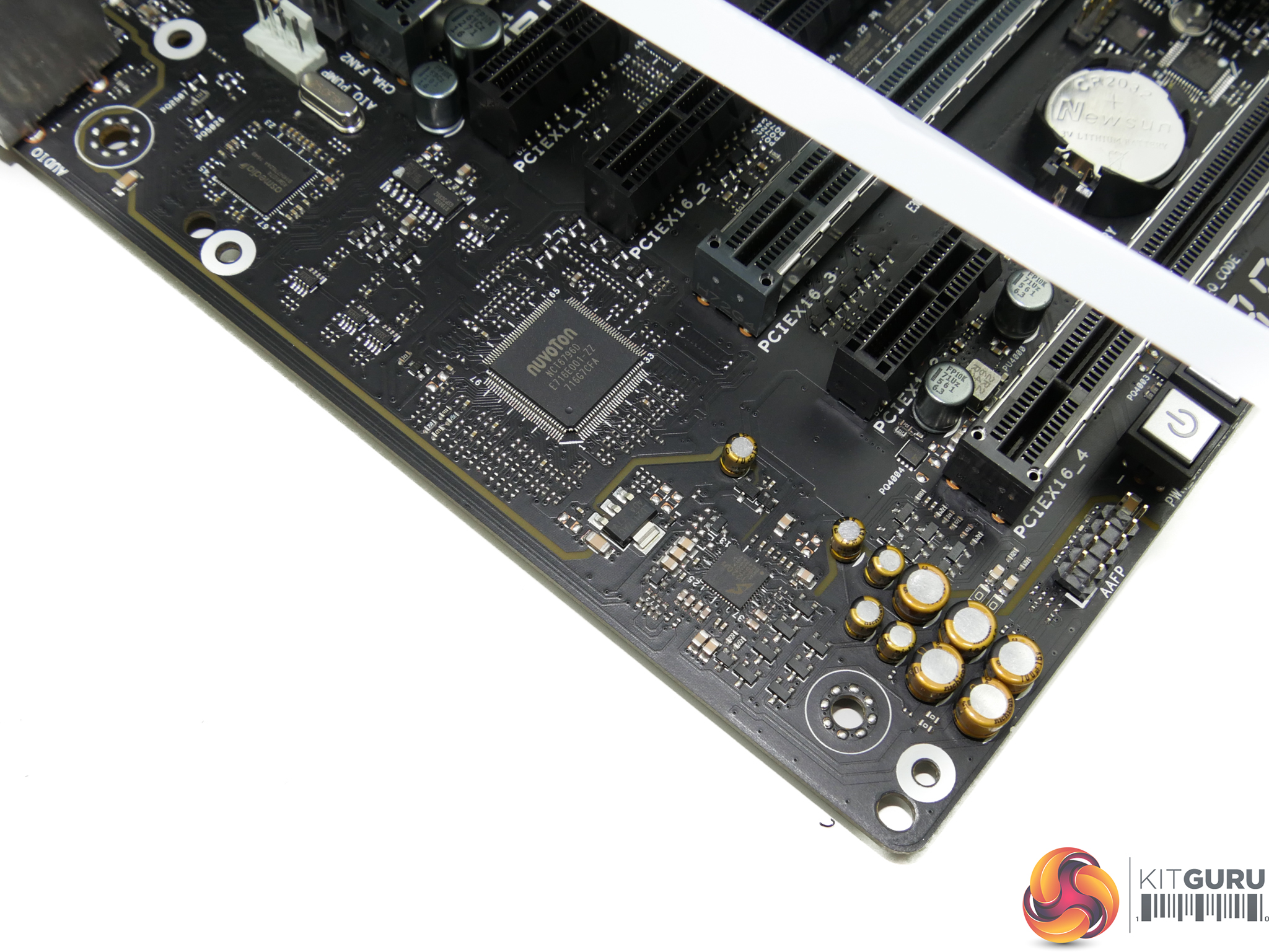
Up to three high-bandwidth PCIe cards, such as graphics cards, can be used with the X299-Deluxe. The three fattened ASUS SafeSlot connectors are where users should install graphics cards or high-bandwidth storage devices (such as ASUS’ Hyper M.2 x16 card).
The three SafeSlot connectors run at x16/x16/x8 with a 44-lane CPU or x16/x8 + chipset-shared at x4 with a 28-lane chip. A 16-lane chip changes that to x8/x8 but buying a 16-lane chip on X299 is stupid anyway.
That black full-length slot operates at PCIe 3.0 x4 from the CPU. This slot is useful for installing a high-bandwidth PCIe SSD (or M.2 SSD using a riser card) as it always runs at x4 bandwidth with a 28-lane or 44-lane CPU. ASUS intends for this slot to be used with the ThunderboltEX 3 add-in-card that is bundled.
Both PCIe 3.0 x1 connectors operate from the X299 chipset but neither of them is free of bandwidth restrictions. The first x1 slot shares bandwidth with the 802.11ad WiGig networking but it is unlikely to be used given its proximity to the graphics card’s x16 slot. The second x1 slot shares bandwidth with SATA port 7.
To save words, the board’s connectivity is significantly adjusted when using a 16-lane Kaby Lake-X CPU and numerous connections are disabled or forced to share bandwidth.
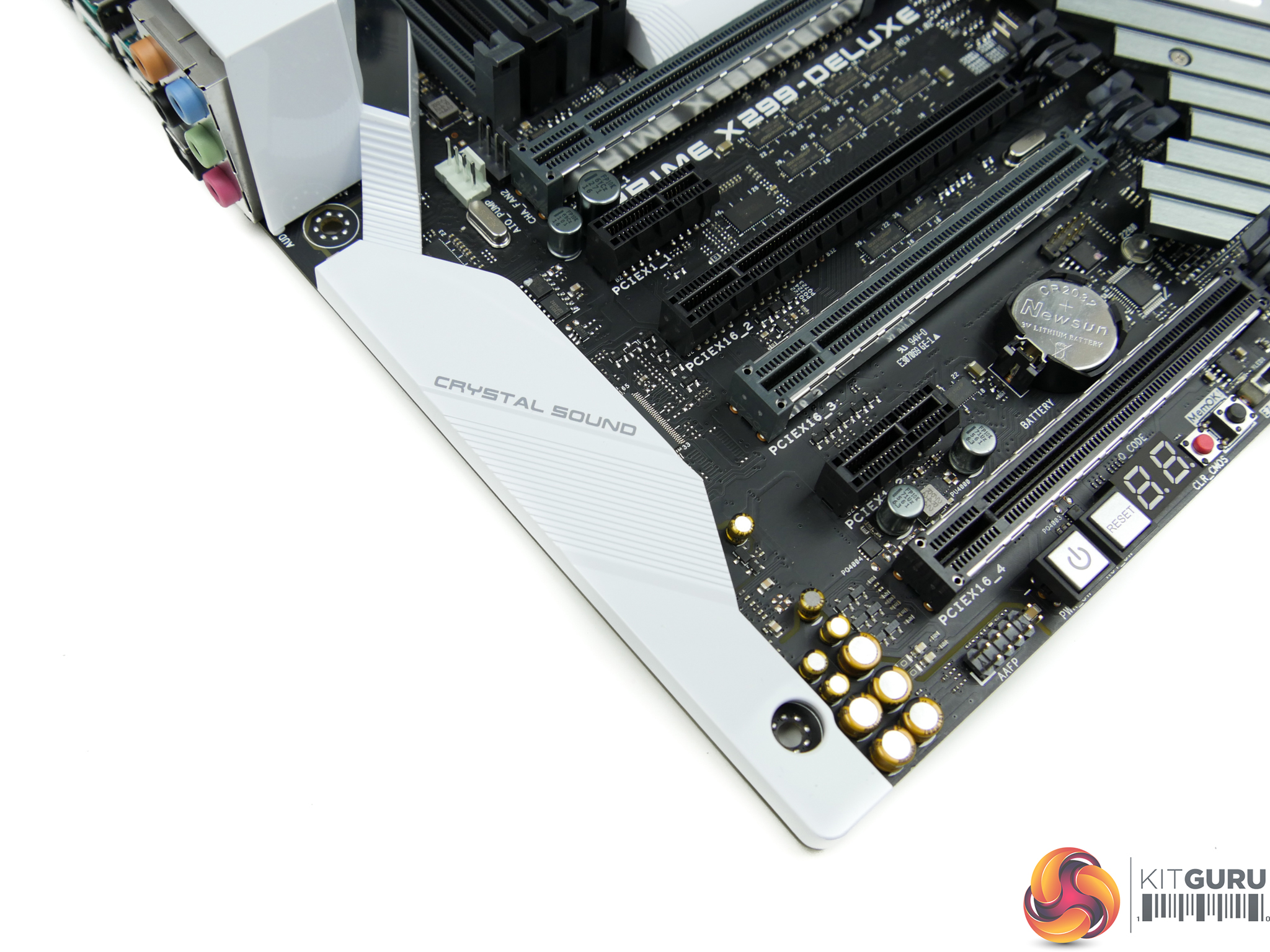
ASUS’ Crystal Sound 3 audio solution is built around a S1220A audio codec with a 113dB line-in SNR and 120dB line-out SNR. Nichicon audio capacitors are also present and there is an impedance sensor that customises levels for specific headphones.
ASUS is keen to point out the effort taken to ensure audio signal quality and noise isolation.
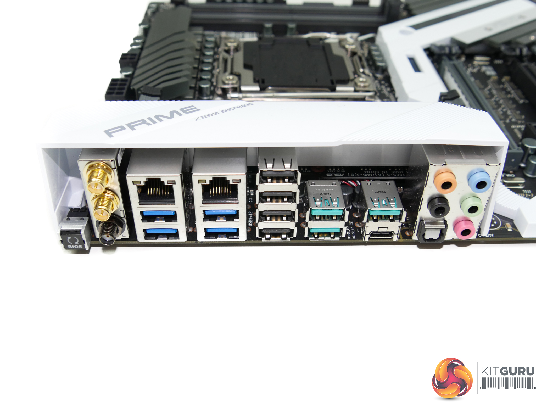
A heavily-packed rear IO is good to see on a premium motherboard that does not feature (potentially) wasted space with display outputs.
ASUS’ useful BIOS Flashback button is present and sits next to the three antenna points used for 802.11ac and 802.11ad WiFi connectivity. Dual GbE connections are provided by Intel I219V and I211AT NICs, both of which feature ASUS’ LANGuard ‘protection’.
Beneath the NICs are four 5Gbps USB 3.0 ports, one of which comes directly from the X299 chipset with the other three being routed via a bandwidth-constricting ASM1074 multi-port hub. All four of the chipset-fed USB 2.0 ports are useful for low-bandwidth device and peripheral connectivity. Two sets of two 10Gbps USB 3.1 Gen 2 connections (three Type-A and one Type-C) are provided by a pair of ASMedia ASM3142 chipset, aided by an ASM1543 IC for Type-C logic. Each of the ASMedia chipsets operates in PCIe 3.0 x2 mode from the X299 PCH and therefore splits 16Gbps of theoretical bandwidth between the two ports it feeds.
Finishing off the rear IO connections is the standard set of 3.5mm audio jacks, in addition to an optical SPDIF connector.
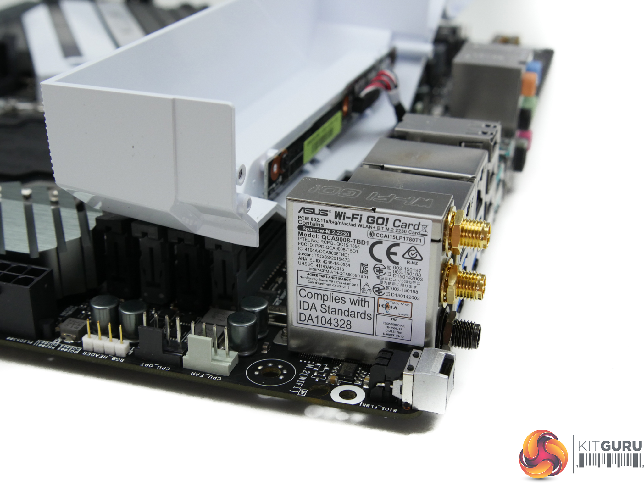
The 802.11a/b/g/n/ac/ad + BT card is packaged as the ‘QCA9008-TBD1’. That model number relates to a Qualcomm-based chipset for 802.11ac/ad and Bluetooth capability.
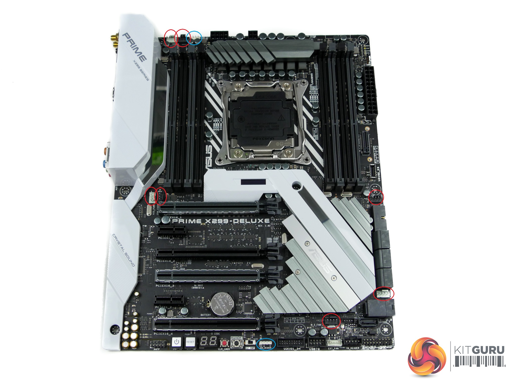
Seven 4-pin fan headers are distributed around the motherboard, with a further three being available via the ASUS Fan Extension card. A Nuvoton NCT6796D chipset is responsible for monitoring and control duties. This is a superb number of fan headers with excellent positioning and a smart spread.
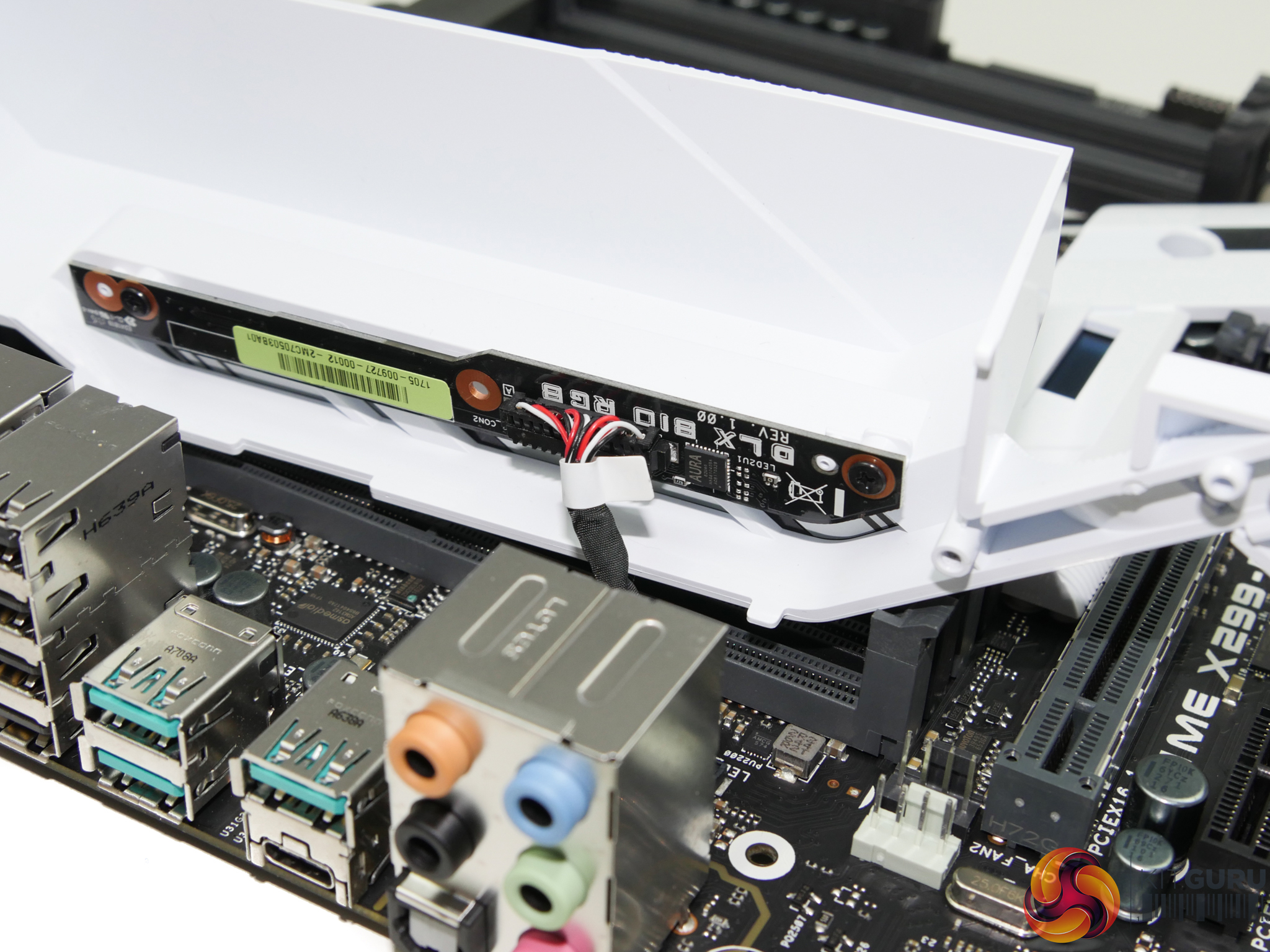
Two RGB LED headers are present – 3-pin addressable along the bottom and a standard 4-pin connection along the top edge.
PCIe slot layout from ASUS is inefficient and severely limiting. The six-slot design cuts down expansion options to a pair of high-powered graphics cards and nothing more, in many situations. Put a pair of ASUS’ own 2.5-slot GTX 1080 Ti STRIX cards on this board and you have blocked all other available expansion slots, included the x4 link for use with the bundled ThunderboltEX 3 card. Mounting a PCIe x4 or x1 slot above the primary GPU slot (by moving the DIMM slots up) would have significantly enhanced expansion options without limiting CPU cooler clearance.
Awesome review…..but my heart leapt when I saw the Air 540, I still mourn the day I sold it, I can still see it leaving my street in the back of the guys car. Goodbye little ‘Sugercube’ I still miss you.
PCIE slot placement has always been a thing for ASUS or at least on every board I’ve ever owned, I remember not being able to SLI because a gpu fouled all of the headers on the bottom of the mobo a few years back. Did you try the 5 way optimisation ; ) I’m just curious knowing how generous it can be with voltages, you will get some customers who click it and just trust it knows what its doing.
“Positioned close to the 24-pin is one of the board’s two M.2 connectors. This PCIe 3.0 x4-only slot is mounted to allow for vertical orientation of an installed M.2 device. A support bracket and screws are included. Vertical mounting is good for putting the device in a direct airflow path, while also minimising the footprint taken up on the board PCB”. – Yup and is all the worst way to put one and will get snapped by any wandering hands of if some one mounts a DVD rom’s that are to log for the slot (yes ppl still use DVD roms).