
The Aorus GP-AP850GM is a distinctive looking power supply featuring a fully modular cable design along with 80 PLUS Gold and ETA-A efficiency certifications. Gigabyte chose to cooperate with a lesser known OEM partner, MEIC, and we are curious to check this platform's performance.
It has been quite some time since our last encounter with a Gigabyte PSU. Although this company is huge and a major player with graphics cards, mainboards and laptops it keeps a very low profile in the power supply market. Probably now that Asus, a major competitor, will enter this field for good with the ROG Thor models, Gigabyte have started enriching its power supply portfolio.
The Aorus P850W and P750W models were announced several weeks ago, however we still can't seem to locate any availability via UK or USA etailers online.
Strangely, as we go to press, the P750W unit isn't even listed on Gigabyte's website. That said, according to our sources the P850W will be available via the US market in mid-September, while it will hit the UK market around the end of September.
Gigabytes Aorus P850W features an appealing external design, according to our taste at least since looks is a subjective matter. Typically for this price range it features a fully modular cable design, while its efficiency certifications place it in the mid-category, since Gold and ETA-A models are more budget-oriented nowadays with Platinum, Titanium and ETA-A+ units addressing users that don't mind investing a significant amount on their new PSU purchase.
There is a single +12V rail which is currently preferred by the majority of brands (and users) while the cooling fan uses double-ball bearings, offering increased reliability especially under tough conditions. Usually most brands prefer rifle or fluid dynamic bearing fans because they produce less noise, however at high operating temperatures the expected lifetime of those bearing types is reduced dramatically, making double-ball and magnetic bearings the best choice.
Please be aware if you can't see the images in this review you will need to disable your ad blocker as they can be known to interfere with the display code.
Read our How We Test Power Supplies HERE
Specifications
| Manufacturer (OEM) | MEIC |
| Max. DC Output | 850W |
| Efficiency | 80 PLUS Gold, ETA-A (88-91%) |
| Noise | LAMBDA-S++ (30-35 dB[A]) |
| Modular | ✓ (Fully) |
| Intel C6/C7 Power State Support |
✓ |
| Operating Temperature (Continuous Full Load) | 0 – 50°C |
| Over Voltage Protection | ✓ |
| Under Voltage Protection | ✓ |
| Over Power Protection | ✓ |
| Over Current (+12V) Protection | ✓ |
| Over Temperature Protection | ✓ |
| Short Circuit Protection | ✓ |
| Surge Protection | ✓ |
| Inrush Current Protection | ✓ |
| Fan Failure Protection | ✗ |
| No Load Operation | ✓ |
| Cooling | 135mm Double Ball Bearing Fan (D14BH-12) |
| Semi-Passive Operation | ✓ (non selectable) |
| Dimensions (W x H x D) | 150 x 87 x 162mm |
| Weight | 1.58 kg (3.48 lb) |
| Form Factor | ATX12V v2.4, EPS 2.92 |
| Warranty | 10 Years |
The manufacturer of this unit is MEIC and this is the first time we have tested one of their designs. The unit is 80 PLUS Gold certified while in the Cybenetics scale it achieves ETA-A and LAMBDA-S++ efficiency and noise certifications respectively.
All cables are modular and the max operating temperature for full load delivery is 50°C, as the ATX specification recommends. The protection features are entirely covered and the unit's cooling is handled by a 135mm double-ball bearing fan, which is suitable for operation under tough conditions.
Finally, the dimensions are compact thanks to the 16cm depth and the weight is kept low as well. The provided warranty according to Gigabyte is up to ten-years, depending on the region. This is a good sign especially for a new platform like this one, showing that there is high confidence in its reliability through time.
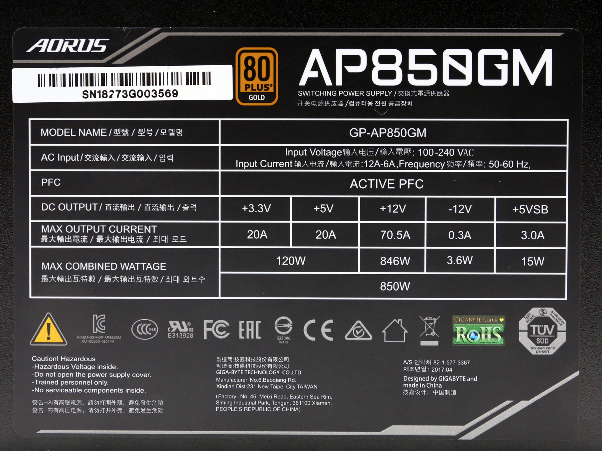
Power Specifications
| Rail | 3.3V | 5V | 12V | 5VSB | -12V | |
| Max. Power | Amps | 20 | 20 | 70.5 | 3 | 0.3 |
| Watts | 120 | 846 | 15 | 3.6 | ||
| Total Max. Power (W) | 850 | |||||
The minor rails have 120W capacity, which is enough for any system nowadays and the +12V rail can deliver more than 70 Amps. The 5VSB rail has enough juice as well for a PSU in this Wattage category.
Cables & Connectors
| Modular Cables | ||||
| Description | Cable Count | Connector Count (Total) | Gauge | In Cable Capacitors |
|---|---|---|---|---|
| ATX connector 20+4 pin (660mm) | 1 | 1 | 16-22AWG | ✓ |
| 4+4 pin EPS12V (800mm) | 1 | 1 | 18AWG | ✓ |
| 4+4 pin EPS12V (650mm) | 1 | 1 | 18AWG | ✓ |
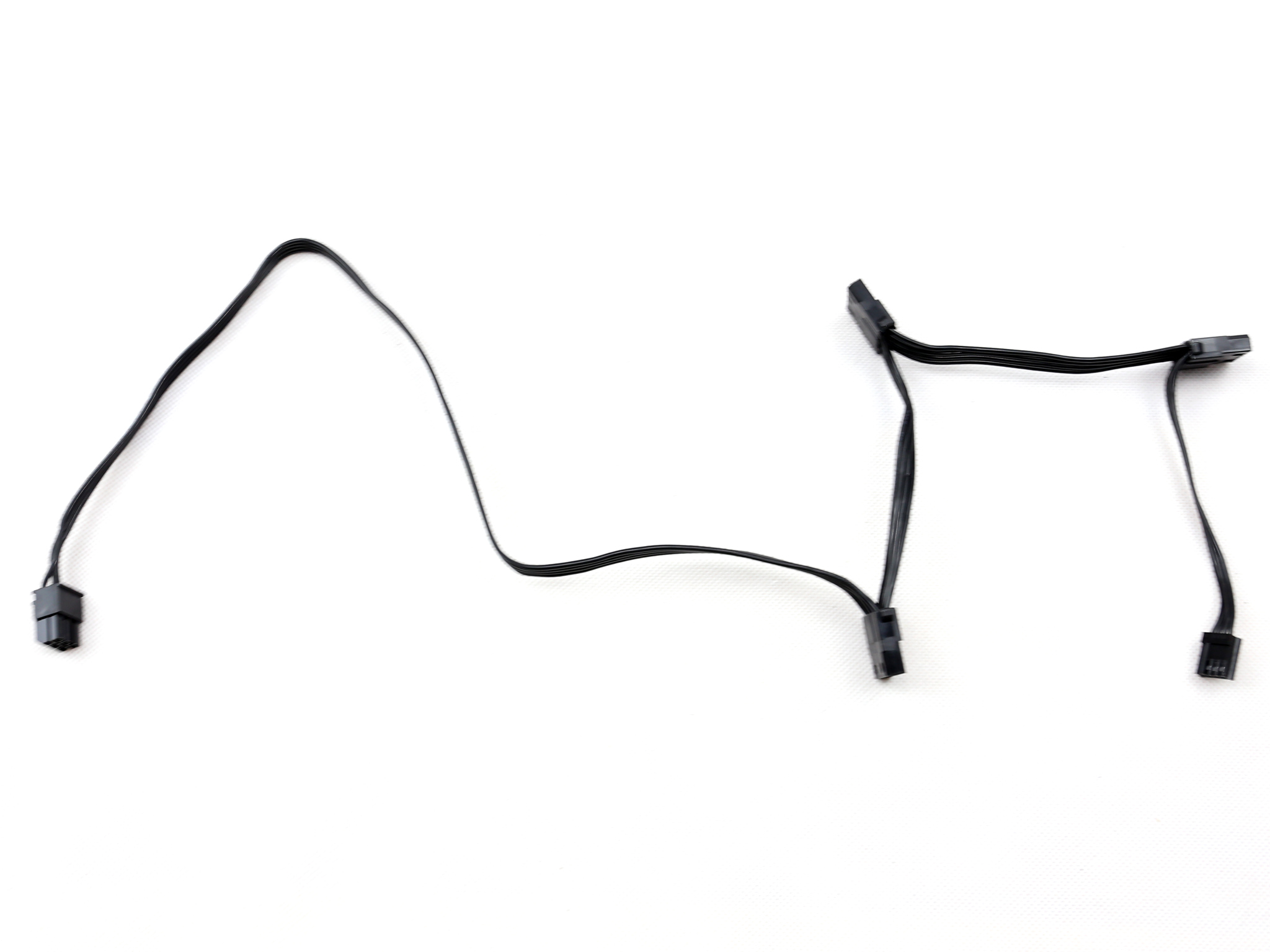
| 6+2 pin PCIe (750mm) | 2 | 2 | 18AWG | ✓ |
| 6+2 pin PCIe (650mm+150mm) | 2 | 4 | 18AWG | ✓ |
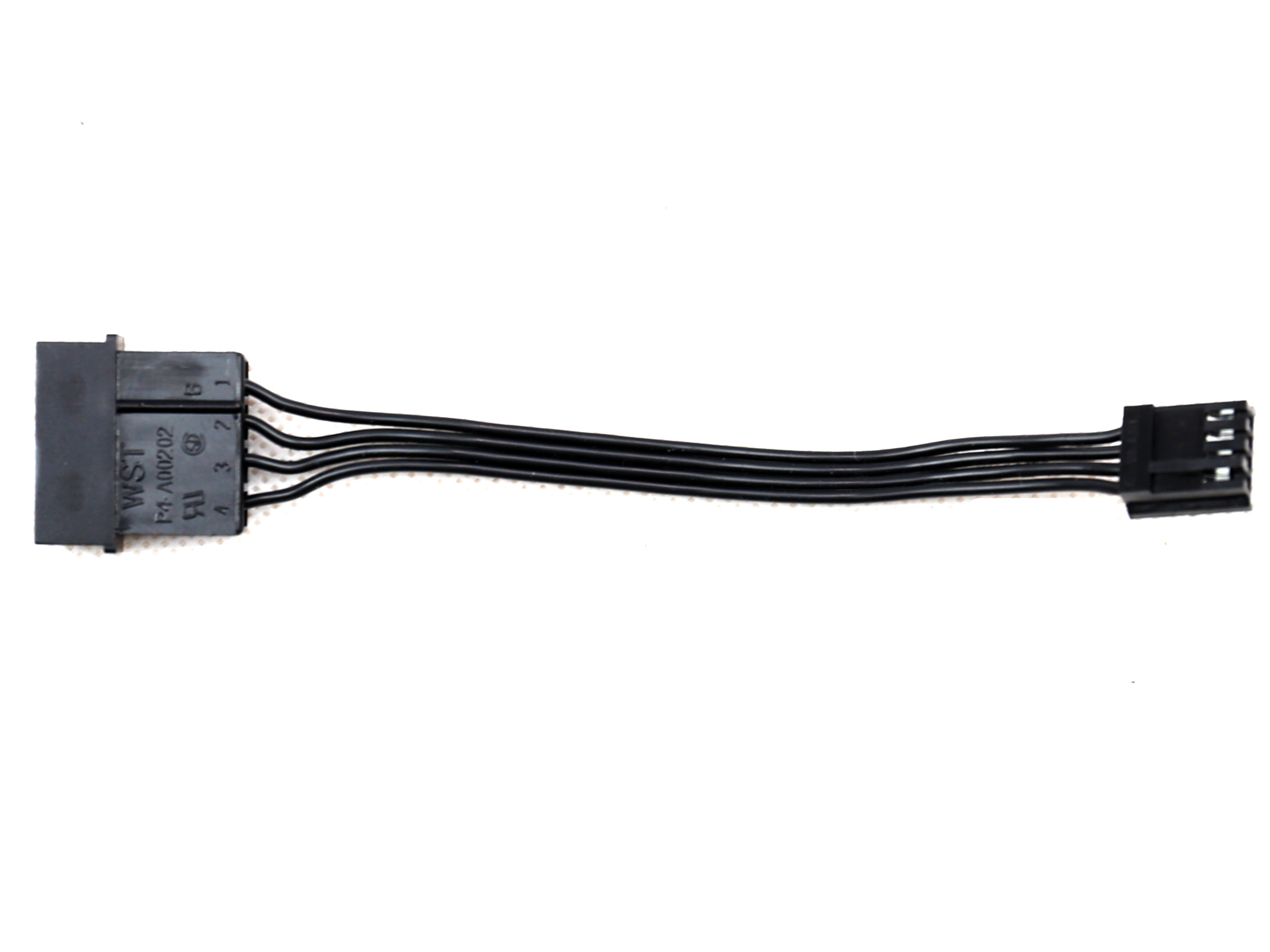
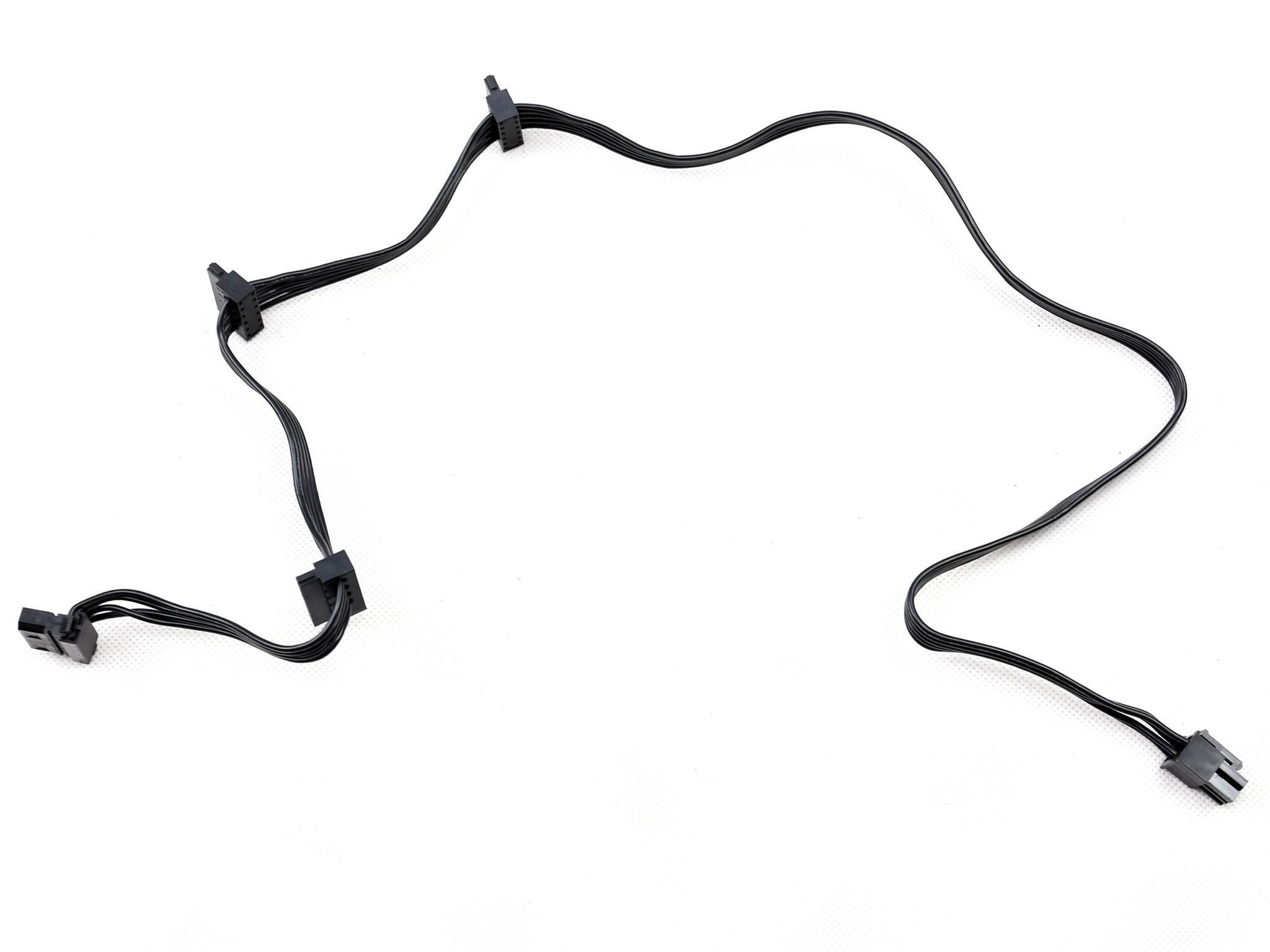
| SATA (550mm+100mm+100mm) / 4-pin Molex (+100mm) | 1 | 3 / 1 | 18AWG | ✗ |
| SATA (460mm+100mm+100mm) / 4-pin Molex (+100mm) | 1 | 3 / 1 | 18AWG | ✗ |
| 4-pin Molex (450mm+100mm+100mm) / FDD (+100mm) | 1 | 3 / 1 | 18-22AWG | ✗ |
| FDD Adapter (+105mm) | 1 | 1 | 22AWG | ✗ |
| AC Power Cord (1400mm) – C13 coupler | 1 | 1 | 16AWG | – |
There are two EPS connectors included with this power supply and they are offered in different lengths. This is a good option if you need only one, as you can pick the cable length to best suit your chassis. If you need both however, and you are using a large chassis, then this isn't ideal. Gigabyte could get around this by offering another longer cable to get a matching pair to suit all situations.
With six PCIe connectors in total this PSU will easily power a strong gaming system and we appreciate the pair of dedicated PCIe cables. On the other hand, the number of SATA connectors might not be sufficient for some enthusiast users, however we do believe that this won't be a problem for the 4-pin Molex connectors since five of them are provided. So in case the number of provided SATA connectors is not enough, you can always get an adapter as long as you don't need the 3.3V rail.
The distance between the peripheral connectors is too short at 100mm. These should really be 140mm to 150mm particularly for the 4-pin connectors.
The Berg connector which is fixed on a modular cable is not an ideal choice since very few need those nowadays. Gigabyte/MEIC should install an additional 4-pin Molex connector in this cable, or even better a SATA.
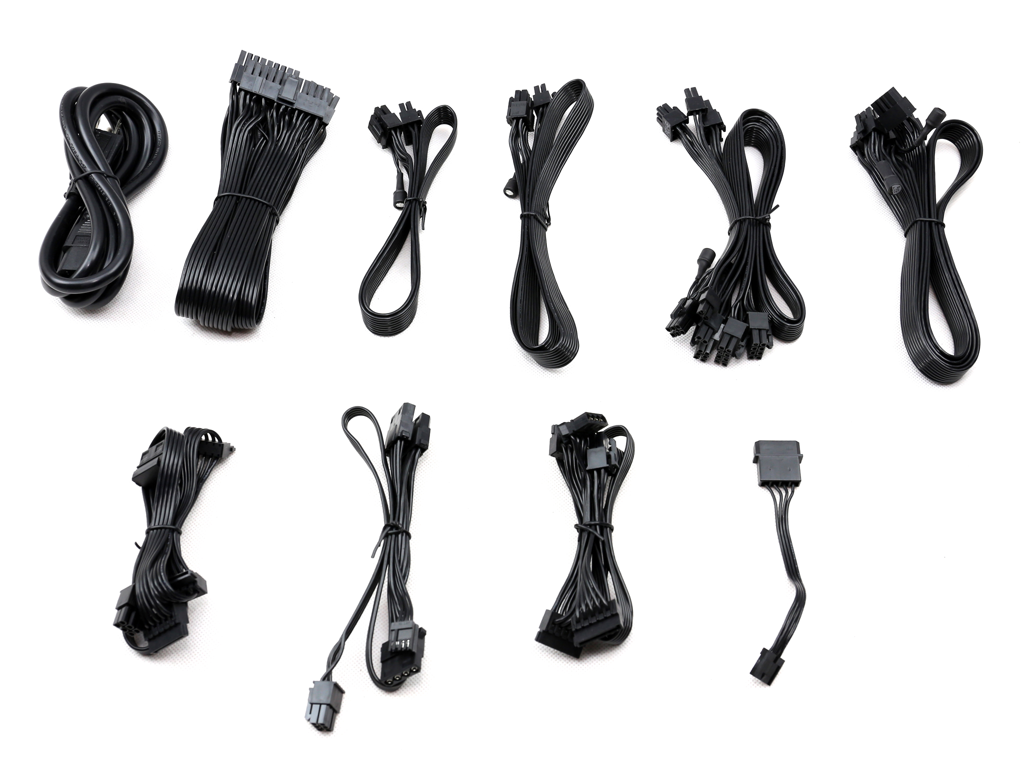
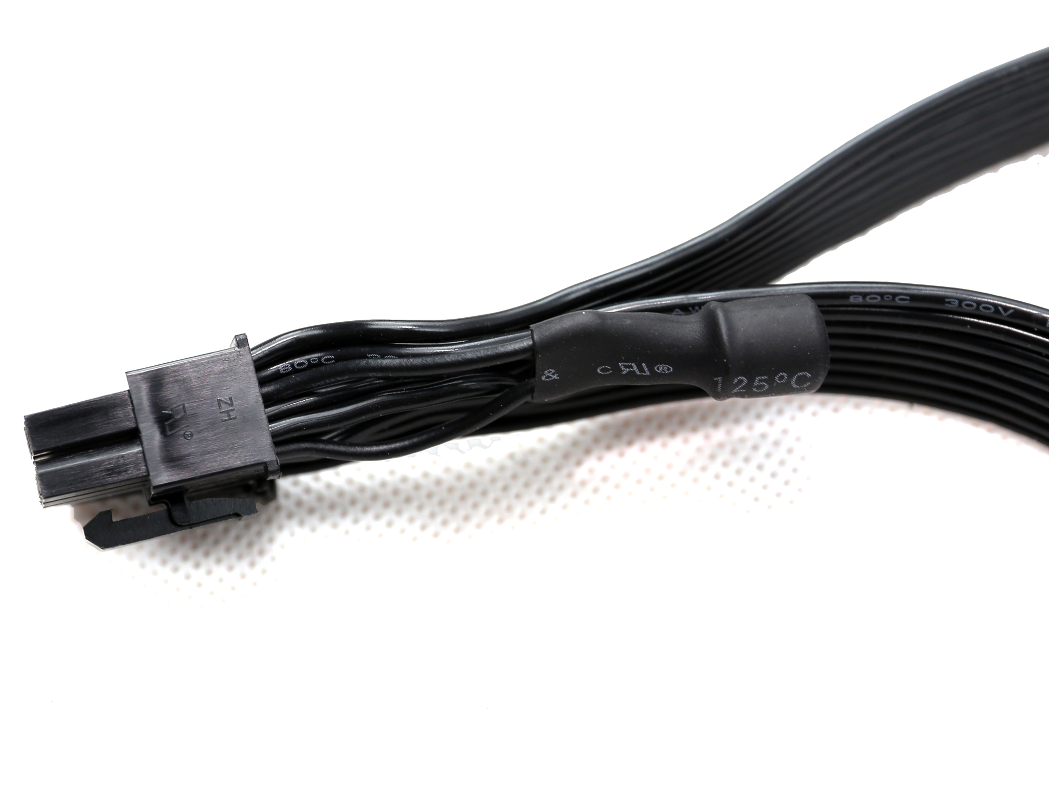
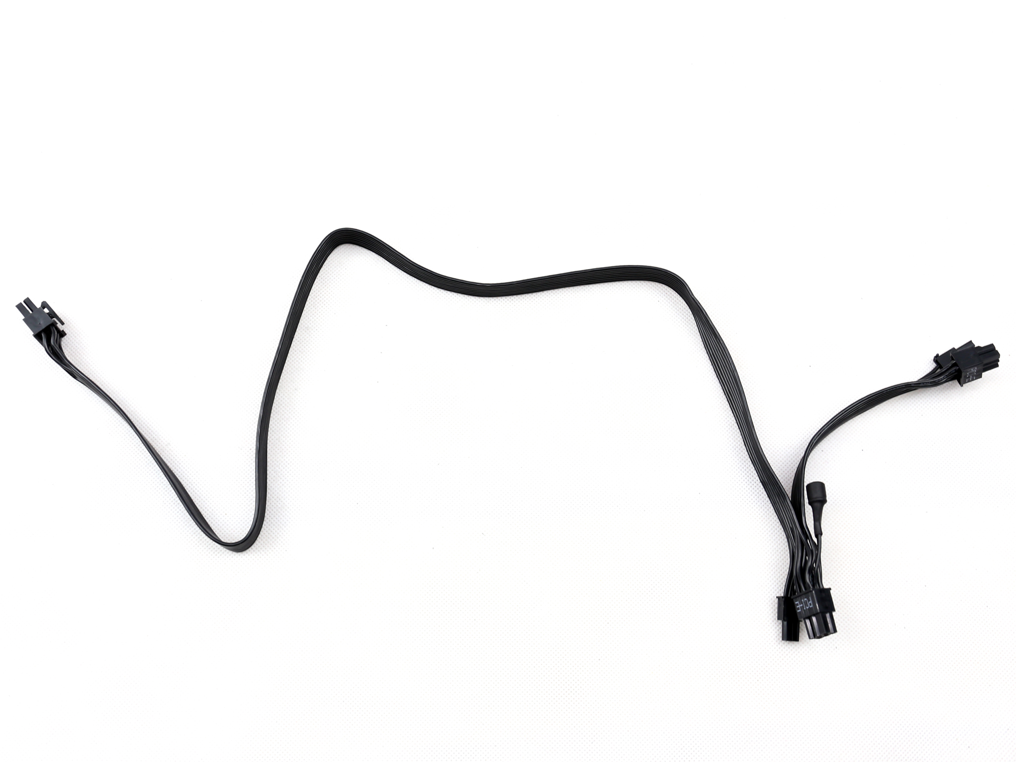
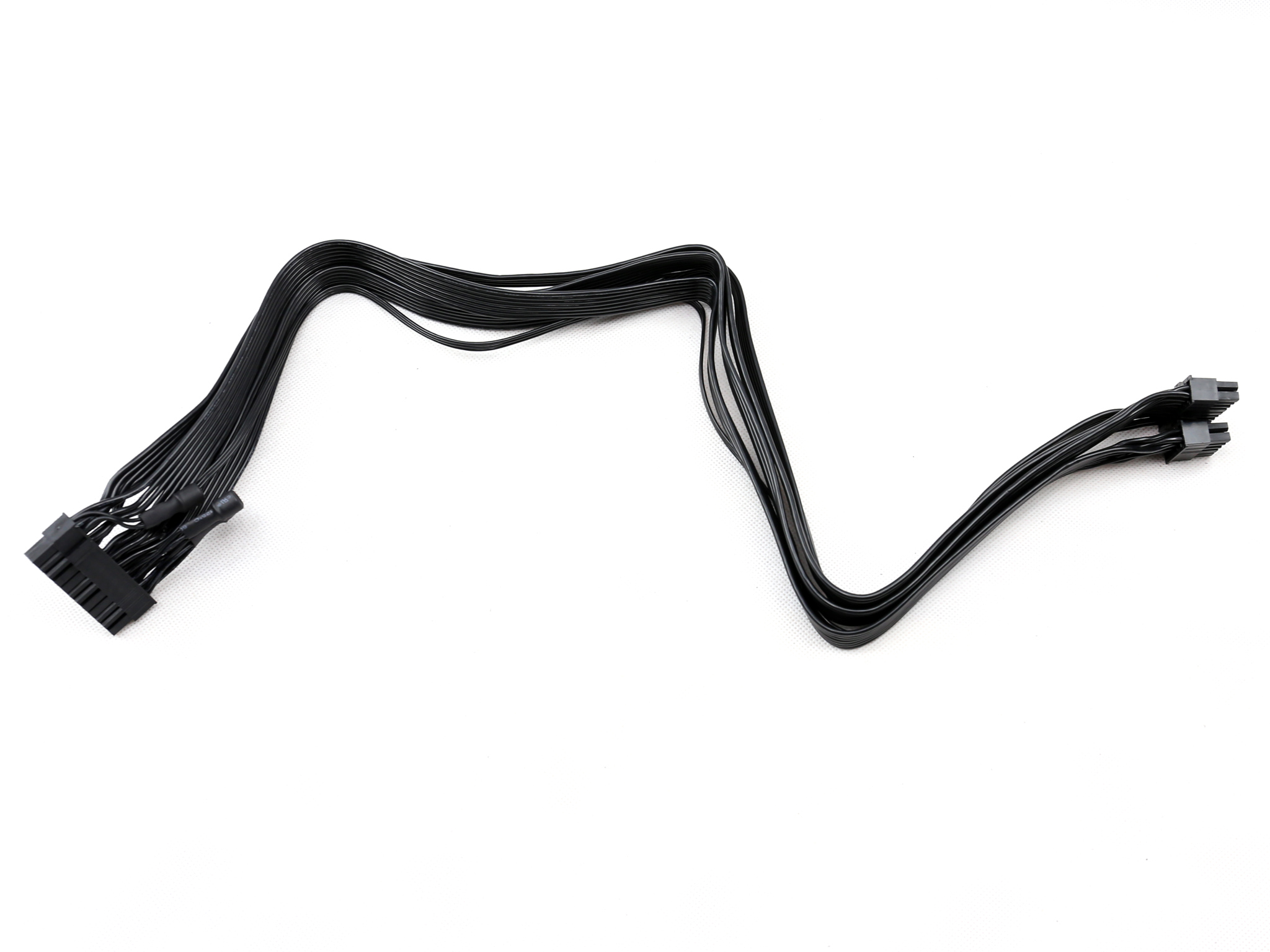
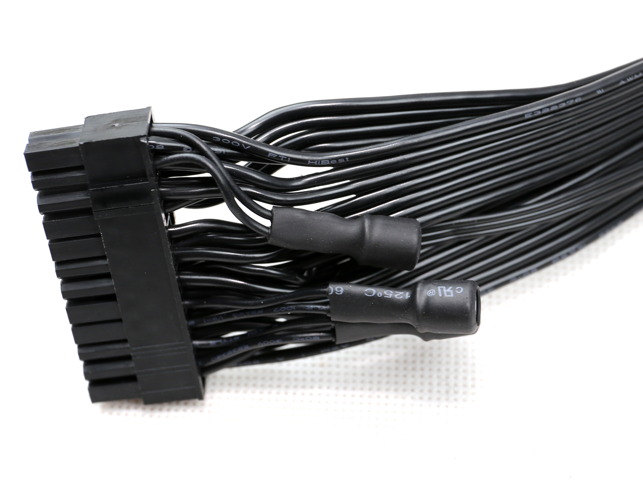
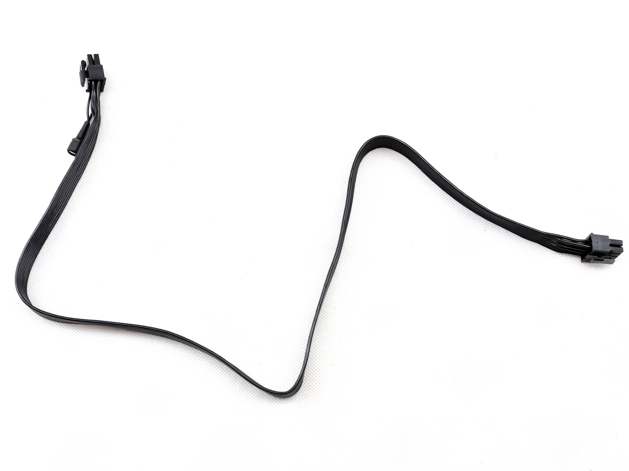
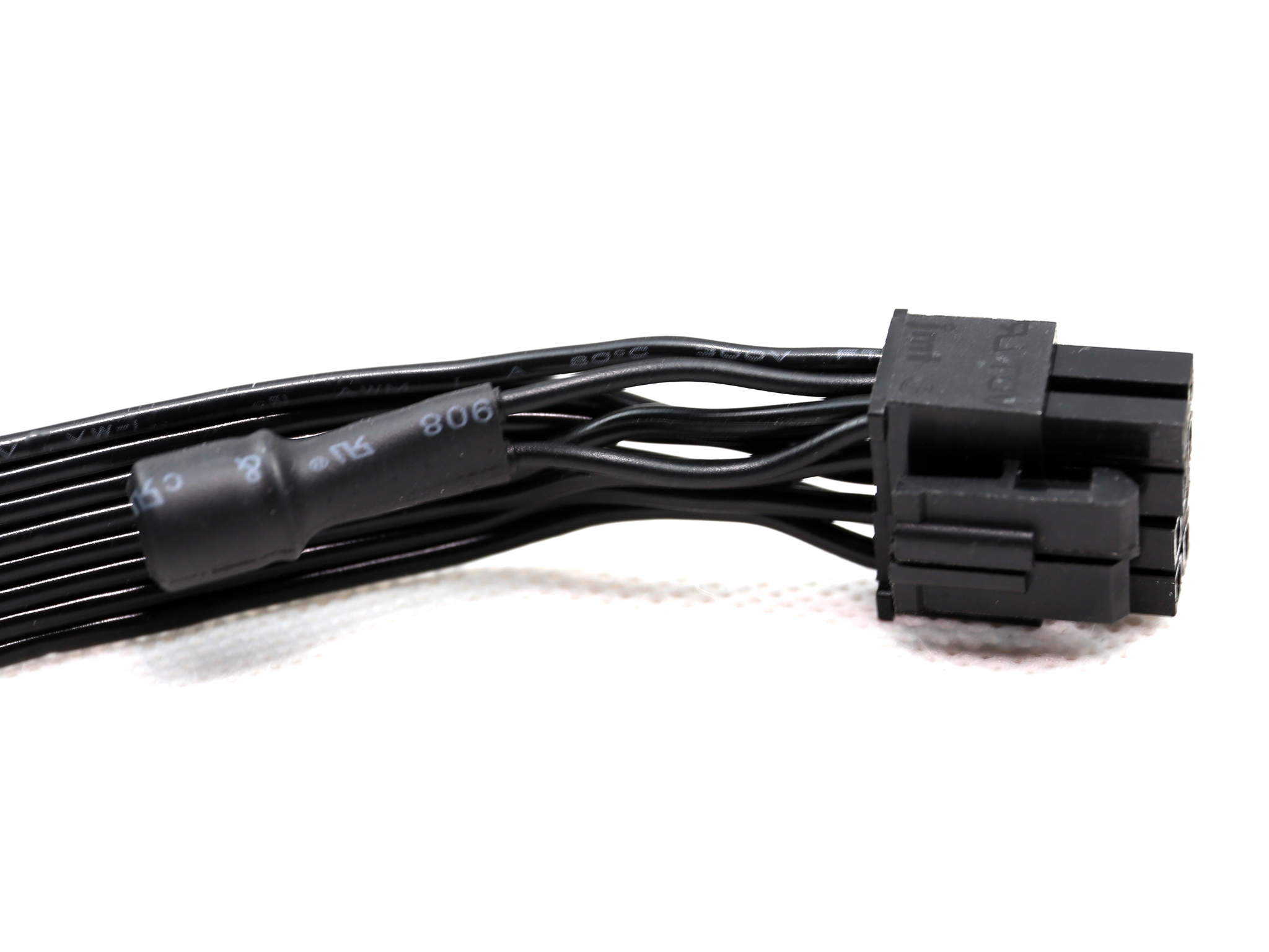
The cables are of high quality and are very flexible. Since Gigabyte/Aorus didn't want to use sleeved, round cables but flat (ribbon style) ones, there was no other way but to have the filtering caps on full show. At least they tried to hide them with black heat shrink which makes them kind of stealthy – well from a distance anyway.
Packaging
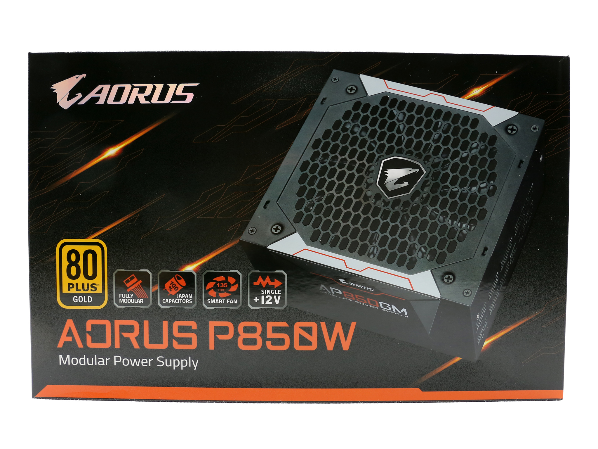
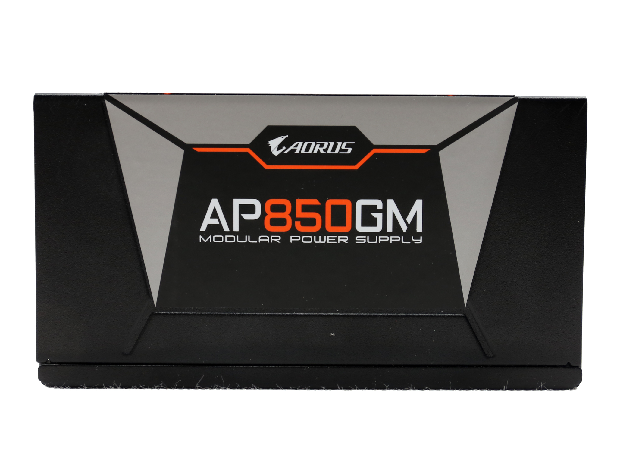
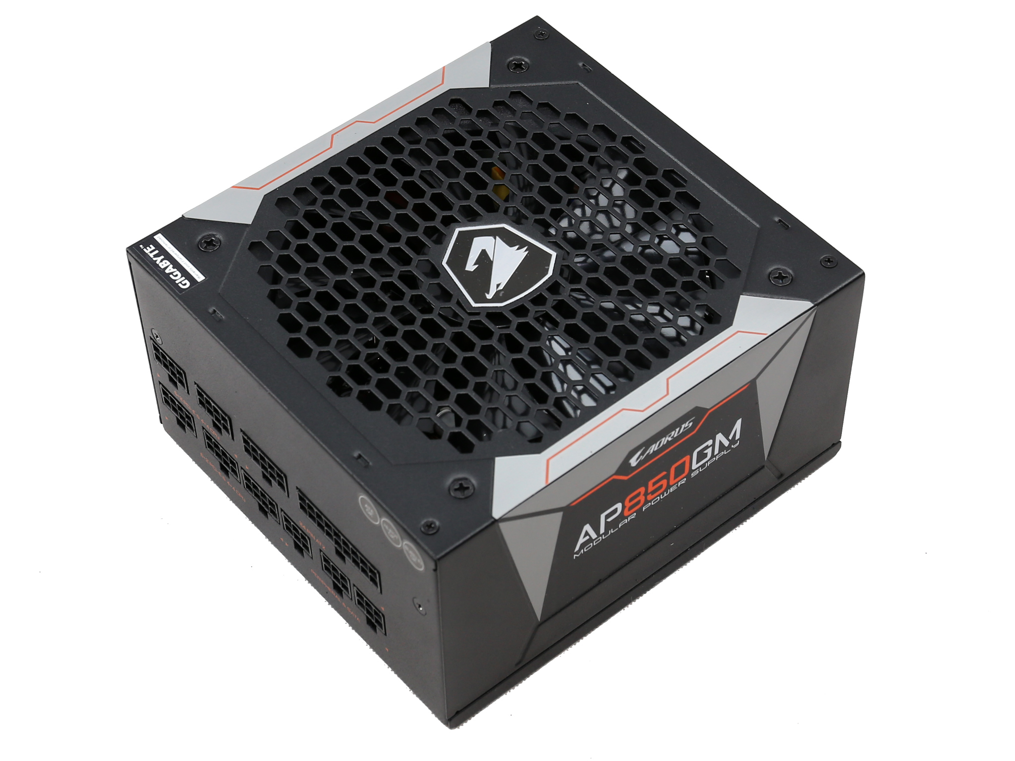
The box has a nice graphics design and vivid colors. At its face there is a photo of the unit with the fan grill exposed.
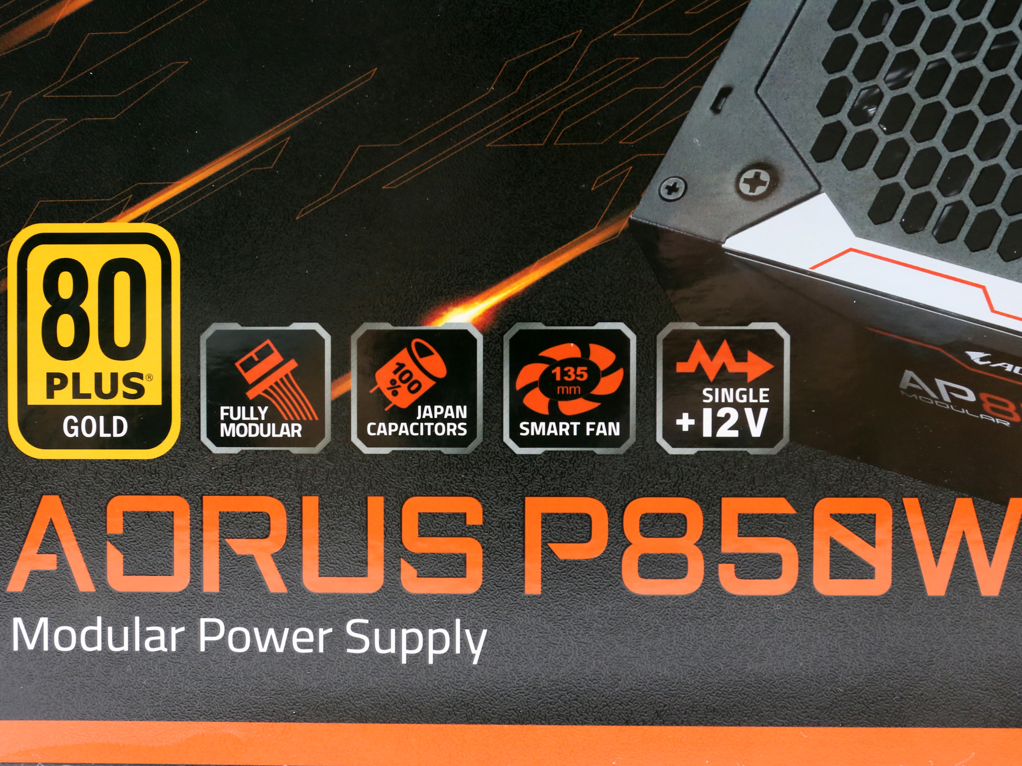
The 80 PLUs Gold badge is quite large and right next to it a number of icons represent some notable features such as the fully modular cable design, the Japanese caps, the smart fan control (like there is a power supply nowadays without fan control) and the single +12V rail.
The model description is located right below all aforementioned icons.

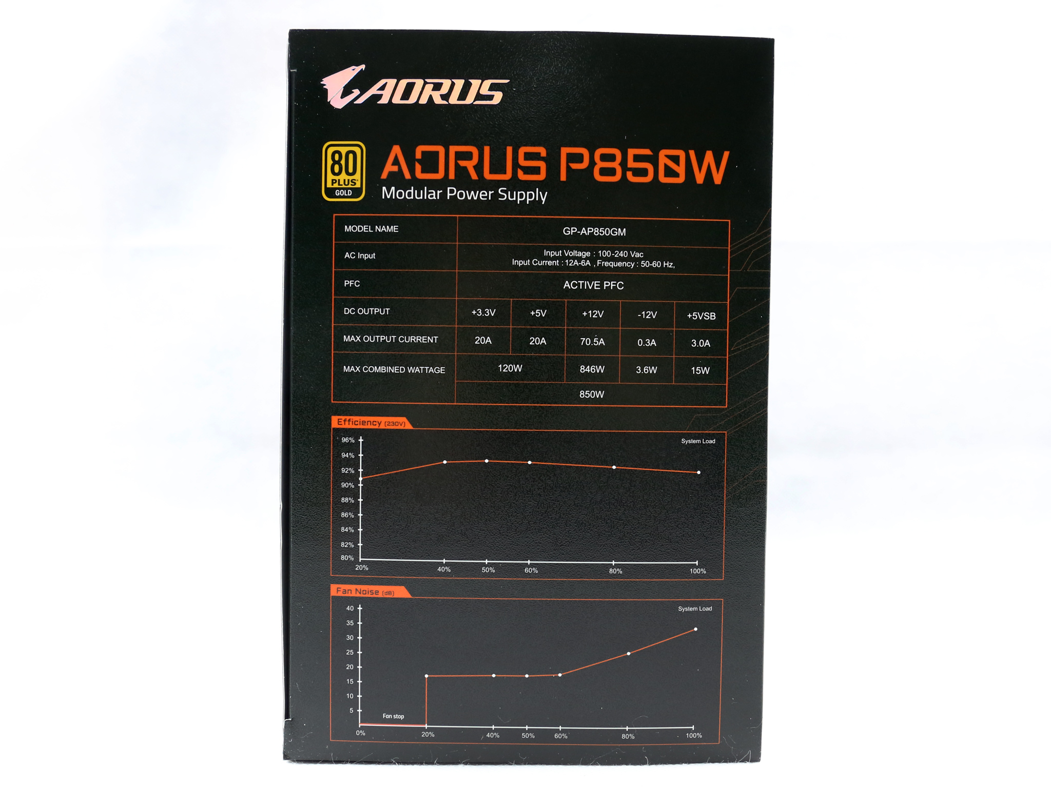
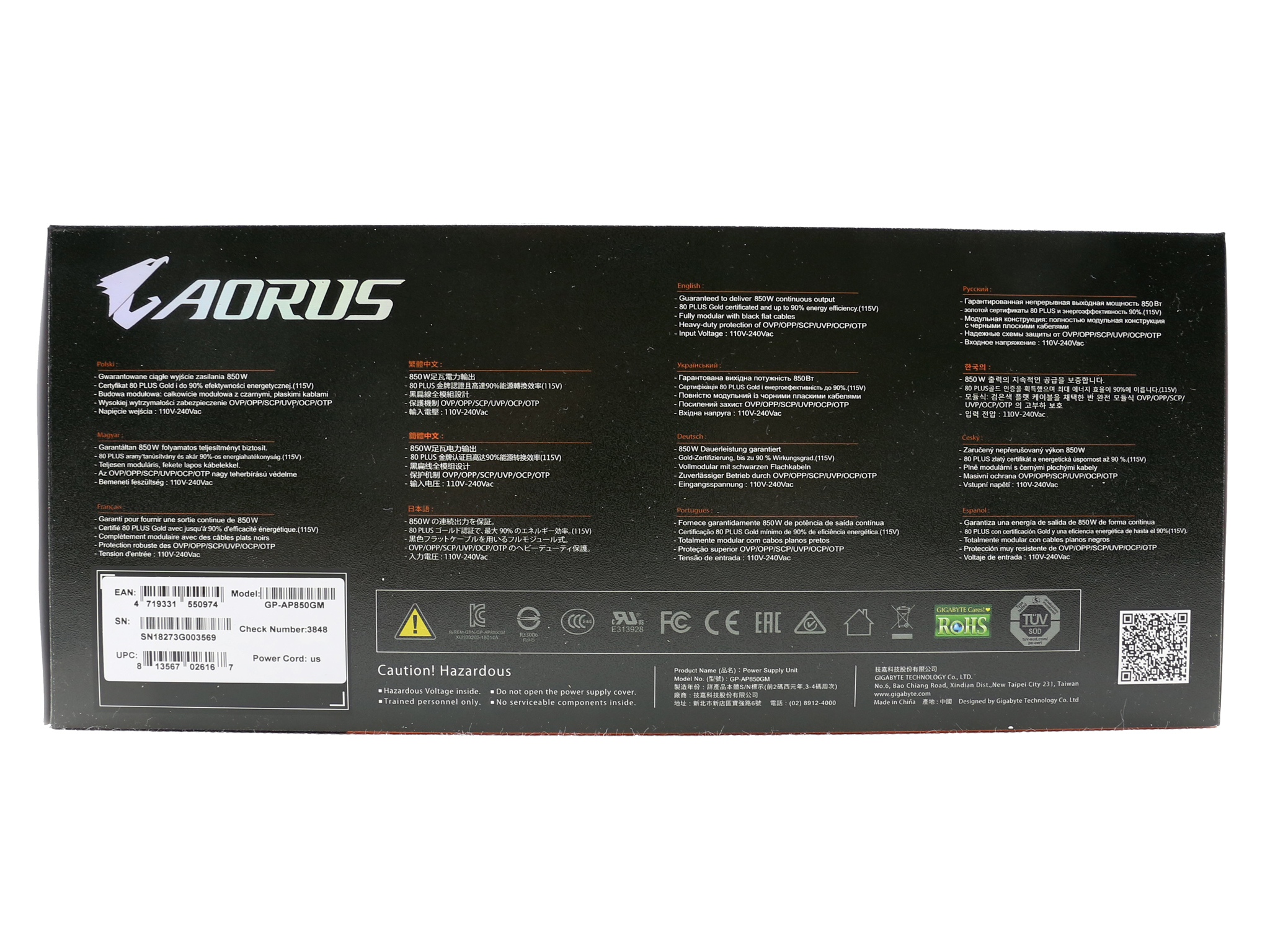
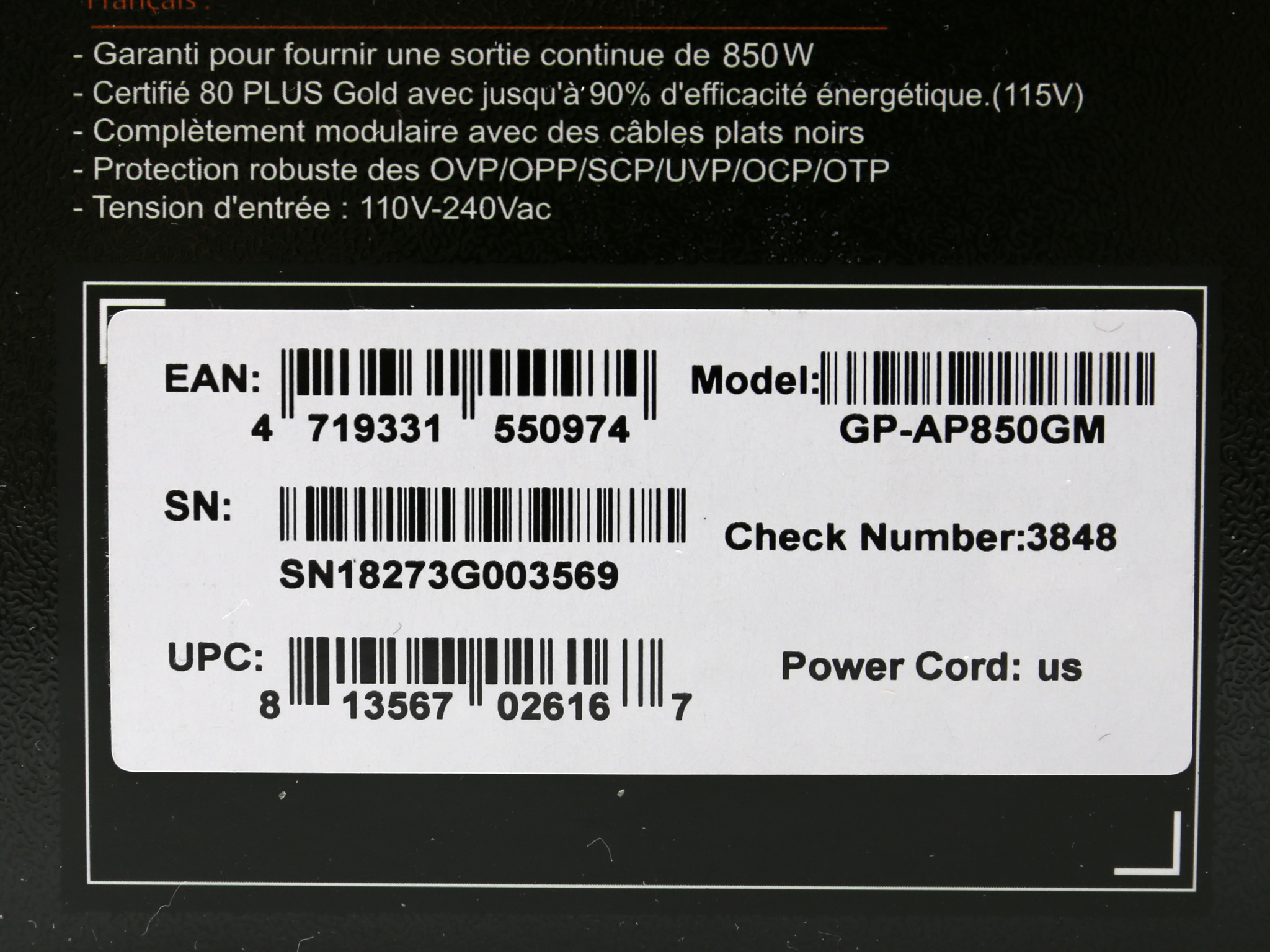
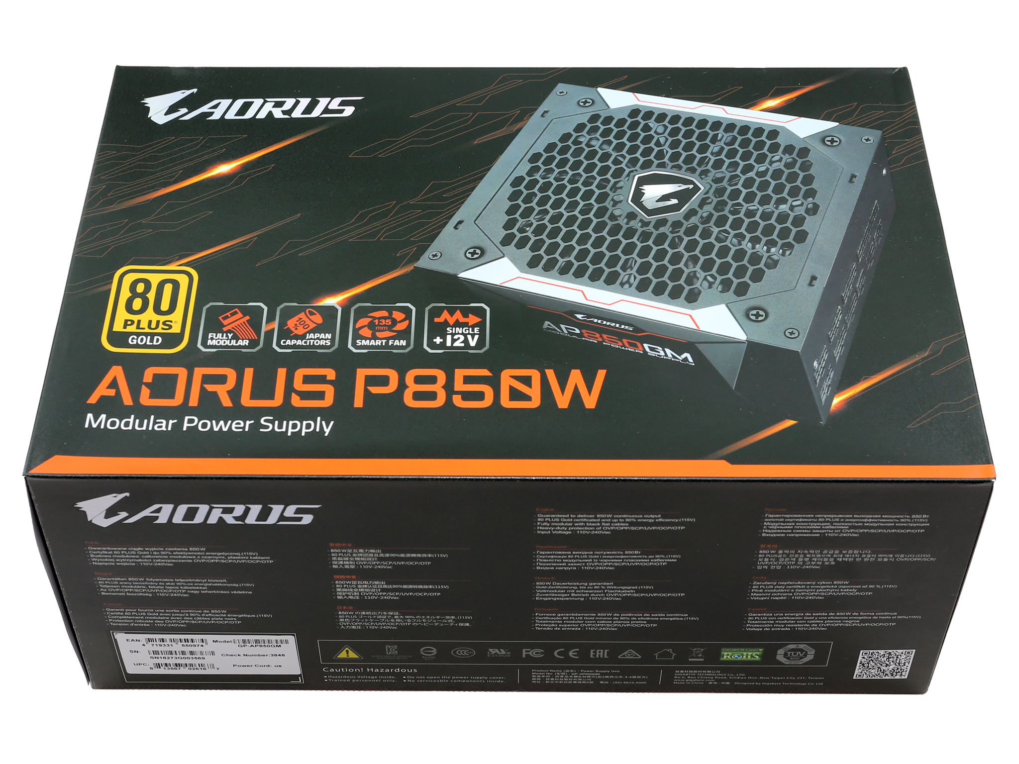
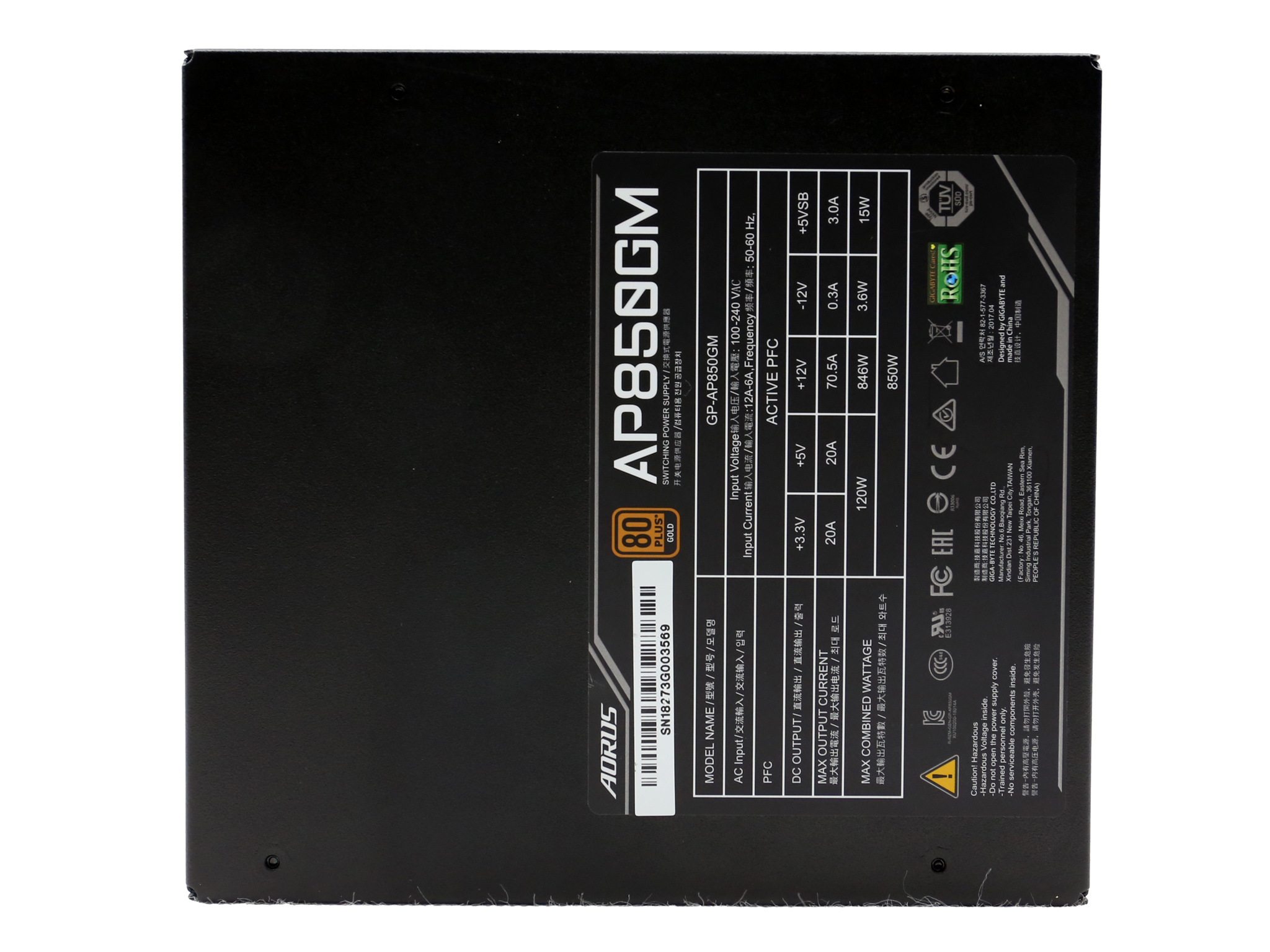
On one of the sides is the technical specifications table along with a list of the provided cables and connectors, while on the other side is the power specifications table and two graphs showing the efficiency and fan noise curves. The serial number along with the model description is depicted on a small sticker, installed at the bottom of the box.
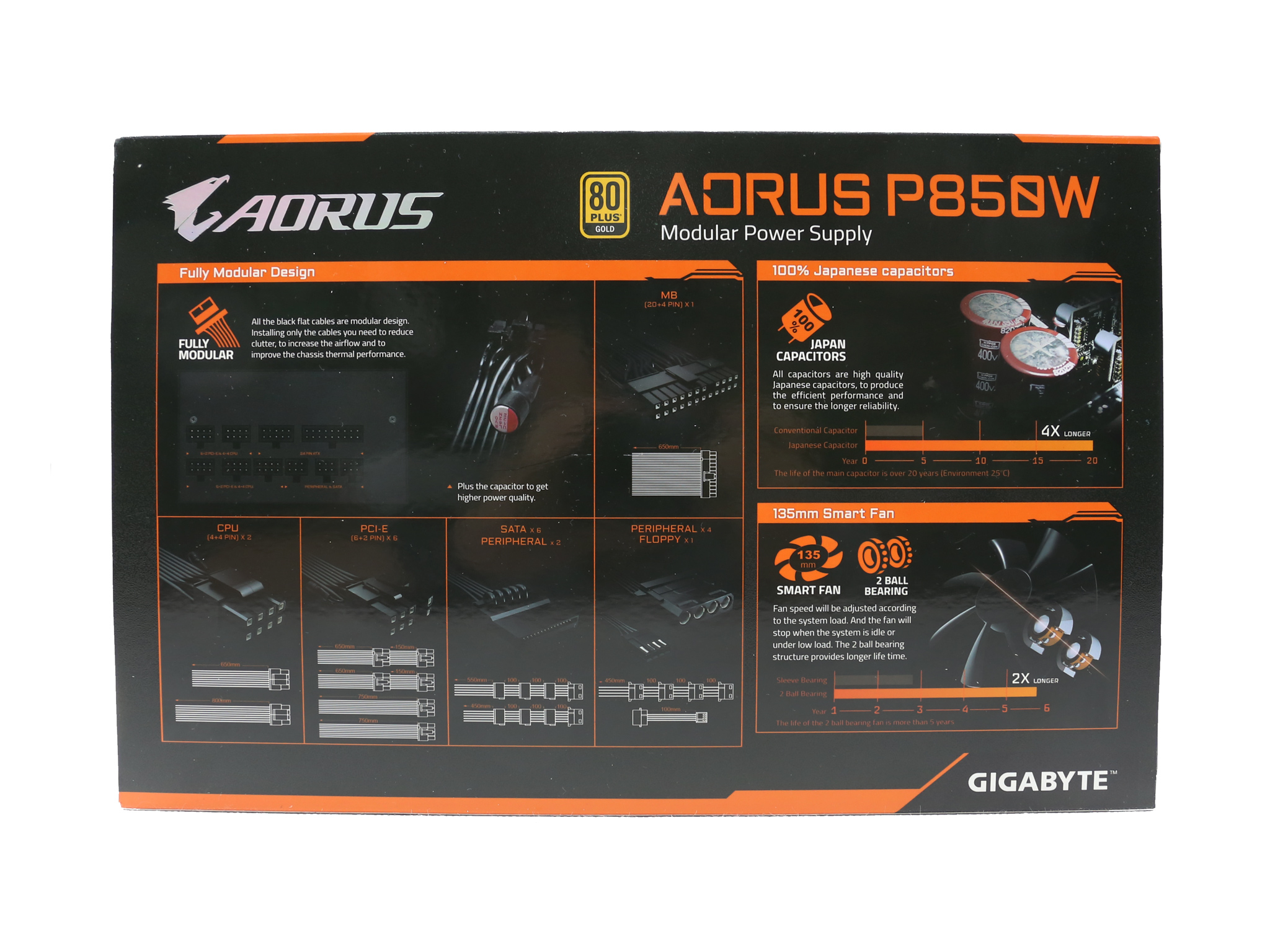
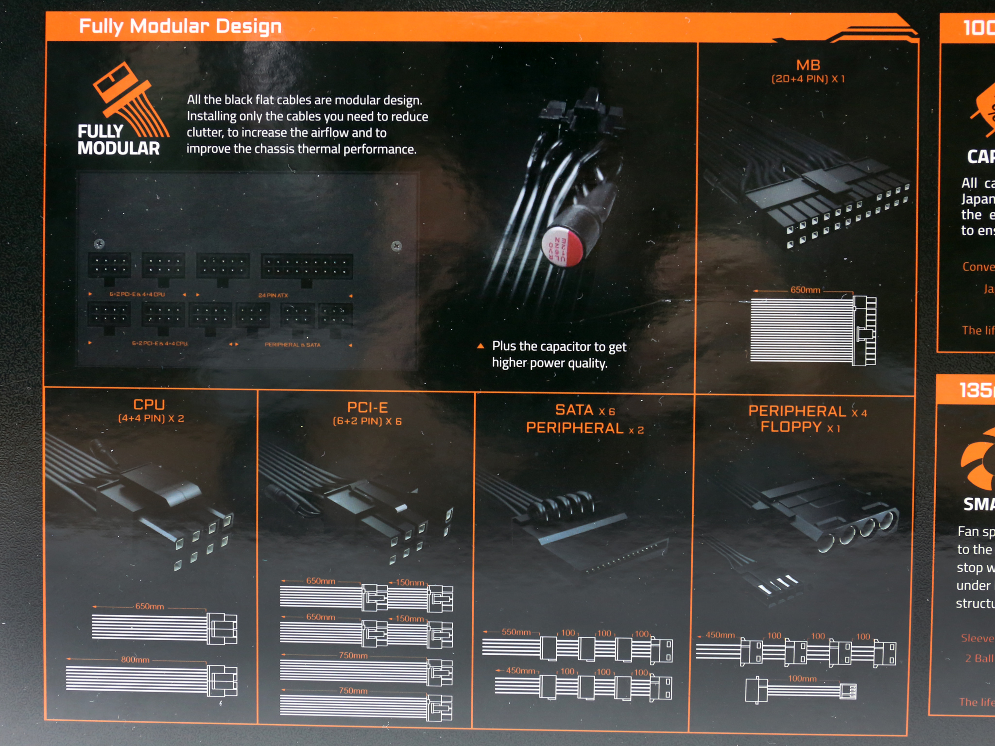
At the rear side of the box Aorus provides more information about the modular cable configuration. There are some interesting photos here showing the caps on the cables, the APFC's bulk caps and the double-ball bearings of the fan which promise double the lifetime of a sleeve bearing.
Contents
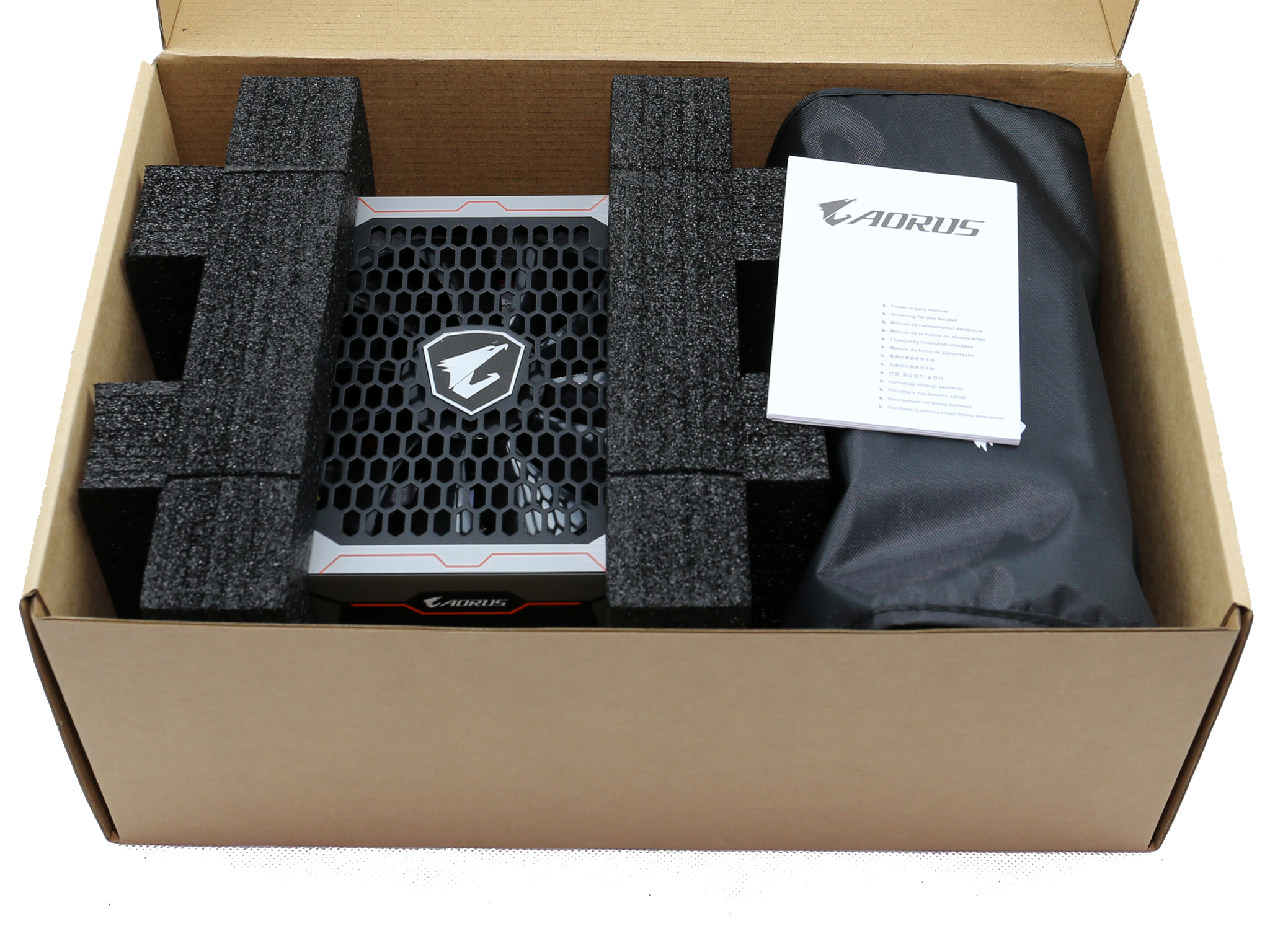
The protection inside the box is good, since the PSU is protected by large foam spacers.
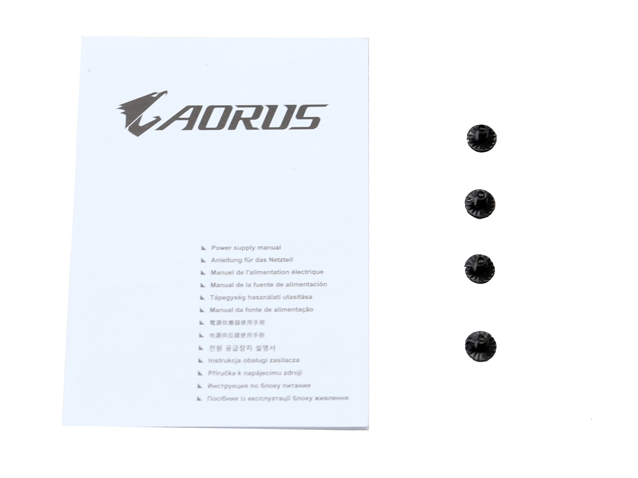
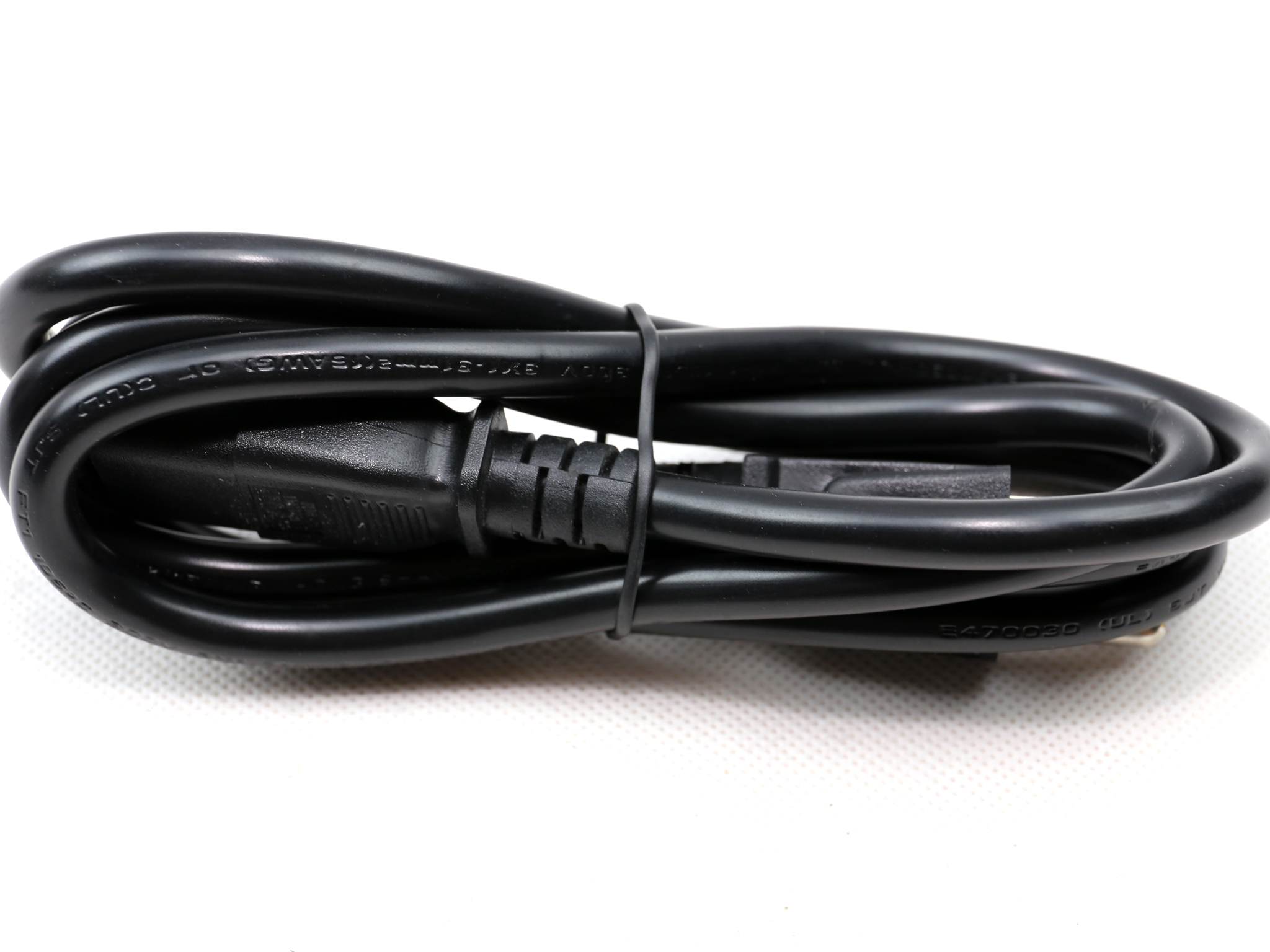
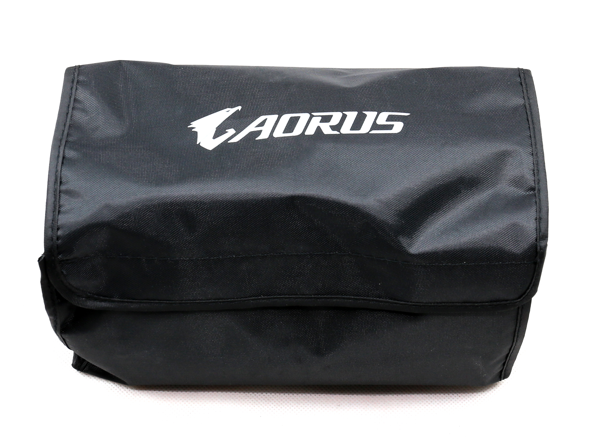
The bundle is not rich, since there are no Velcro straps or even zip ties. You do get though a pouch, to store the unused modular cables. The user's manual is translated in many languages.
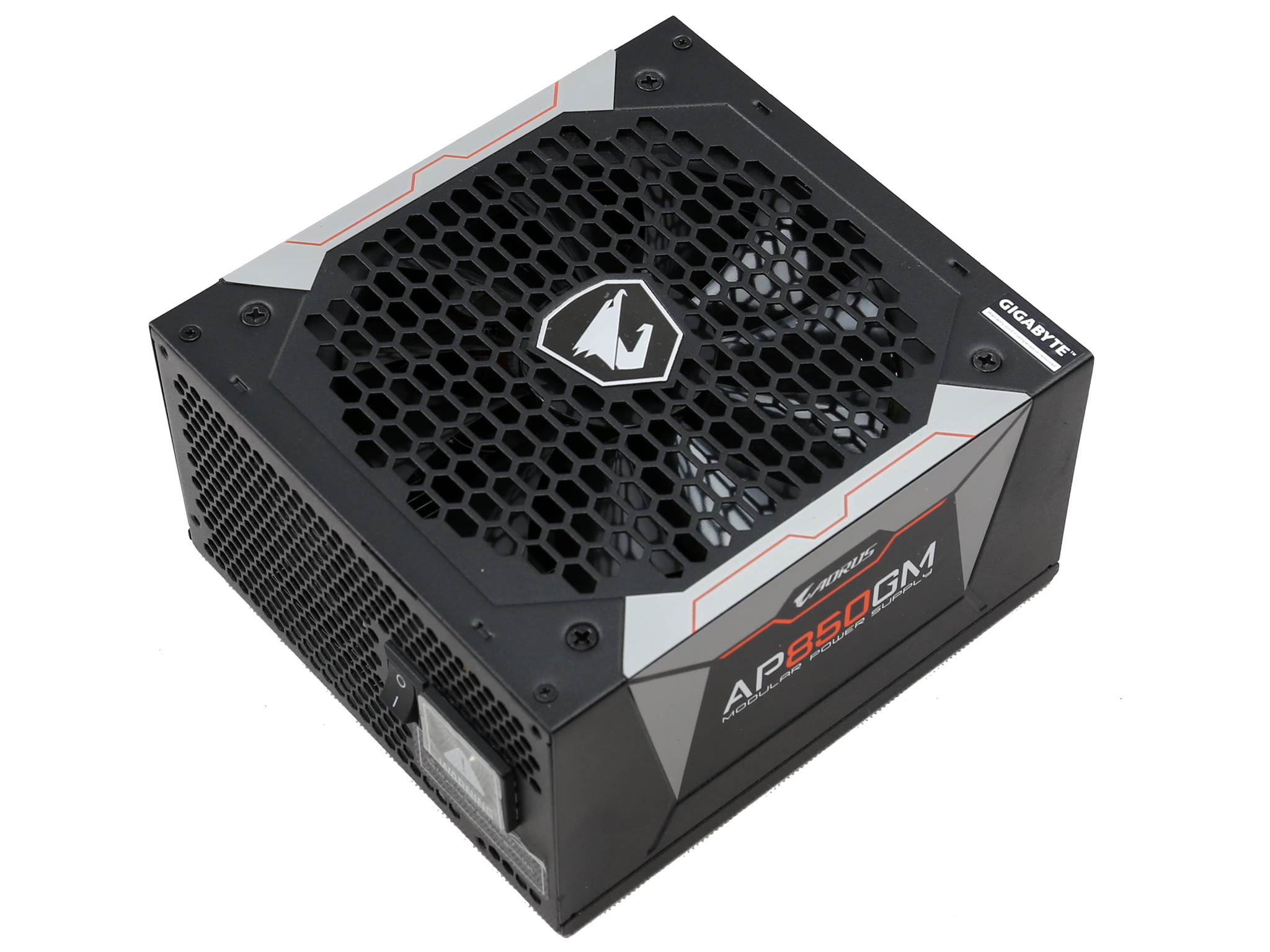
Exterior
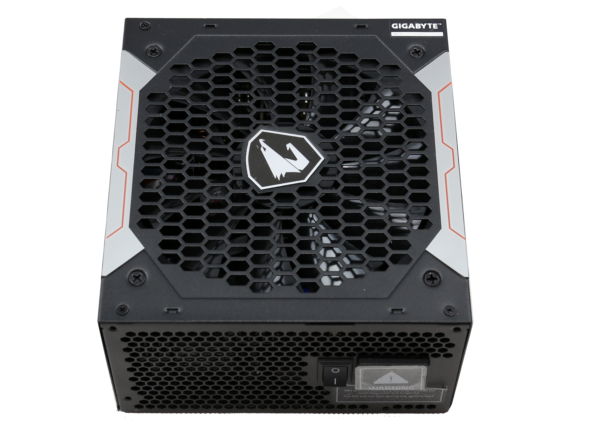
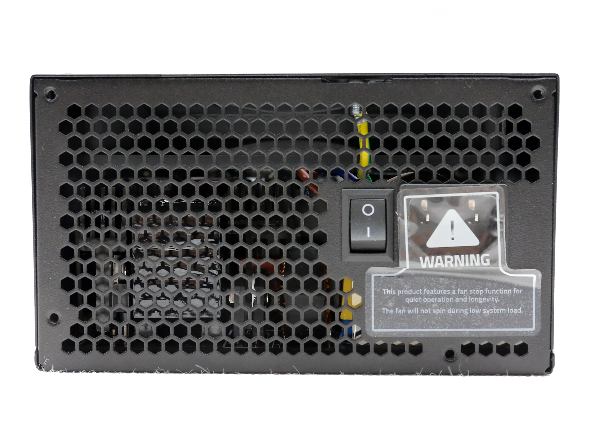
This is a nice looking power supply, mostly thanks to the top side with the octagonal fan grill, featuring the Aorus logo at its center. At the face of the unit the AC receptacle is covered by a sticker, informing that the fan will not spin under light loads. It would be nice if there was a switch for toggling the semi-passive operation on and off.
The stickers on the sides look nice, while a large sticker at the bottom side of the unit depicts the power specifications table along with all certifications that this product carries.
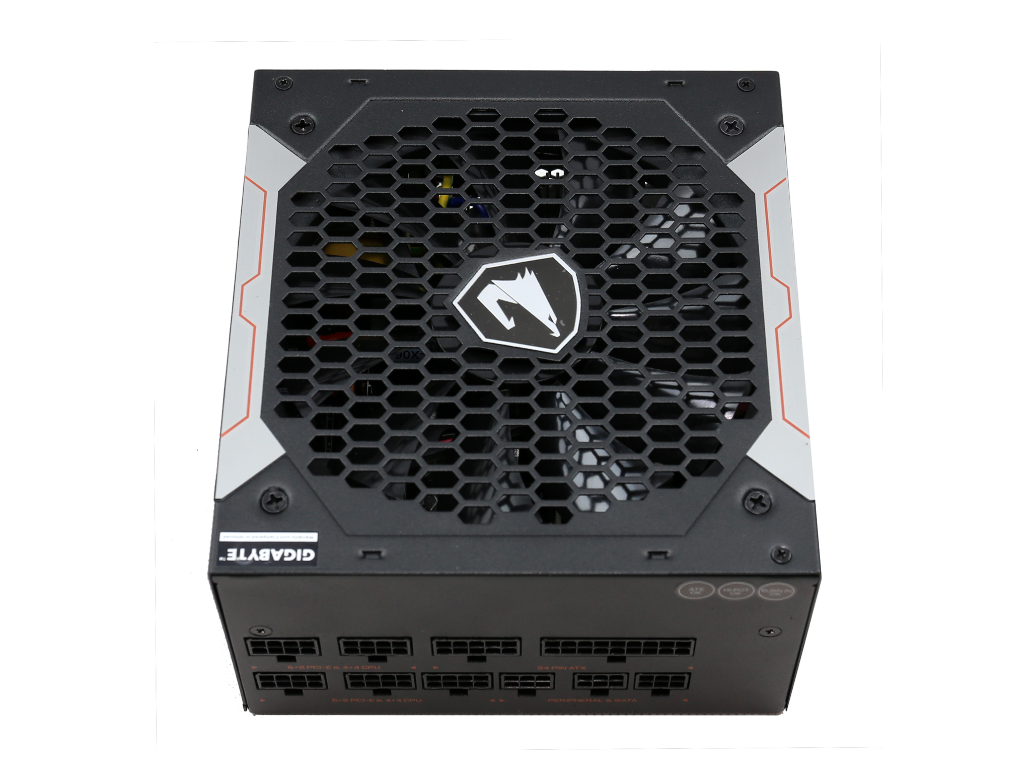
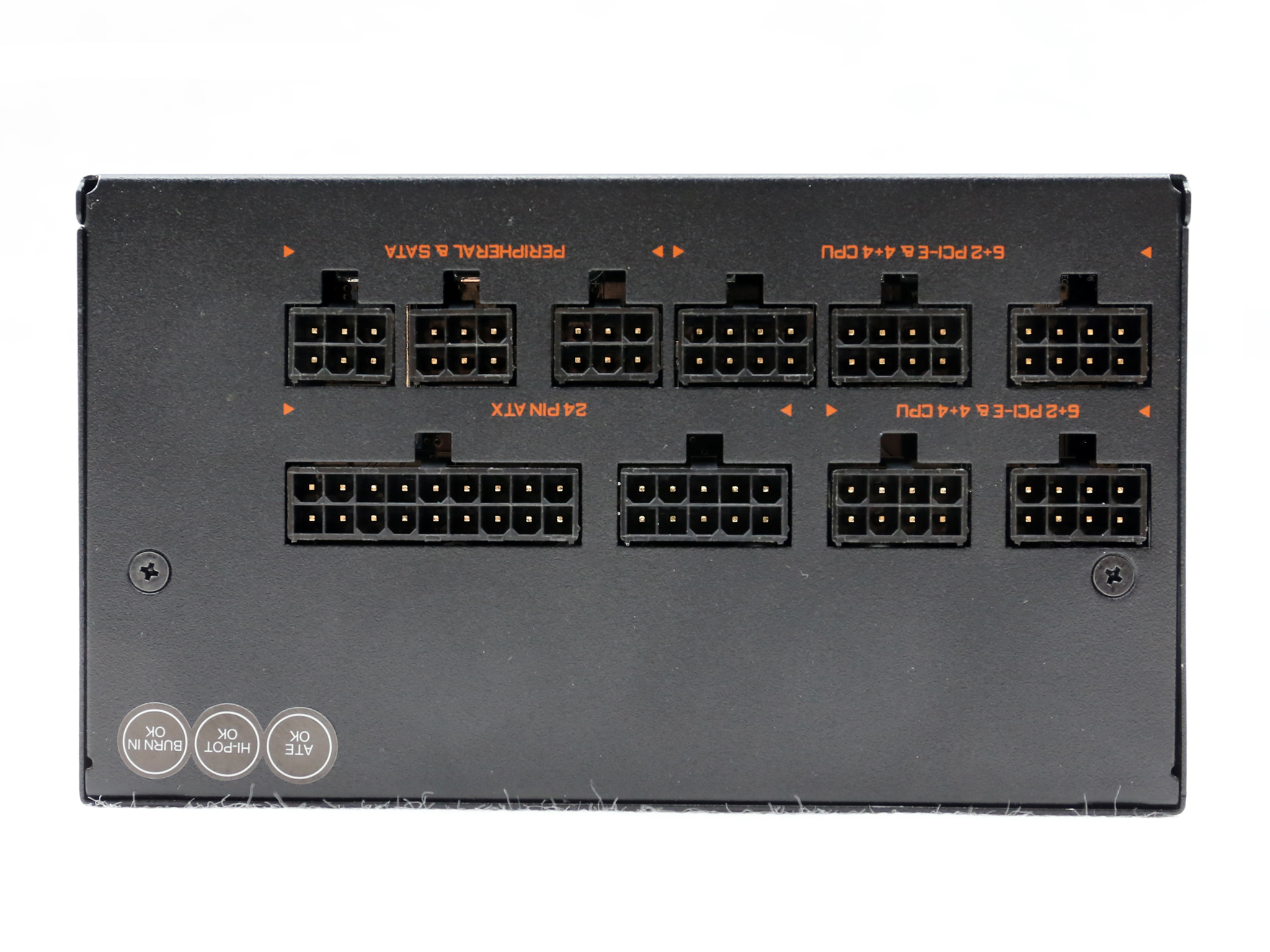
The modular panel has ten sockets in total, which are quite close to each other so it won't be so easy to remove the cables if you use all the sockets.
| General Data | |
| Manufacturer (OEM) | MEIC |
| Primary Side | |
| Transient Filter | 4x Y caps, 2x X caps, 2x CM chokes, 1x MOV, 1x CM02X |
| Inrush Protection | NTC Thermistor & Relay |
| Bridge Rectifier(s) |
2x GBU1006 (600V, 10A @ 100°C)
|
| APFC MOSFETS |
2x Alpha & Omega AOT42S60 (600V, 25A @ 100°C, 0.28Ohm @ 150°C)
|
| APFC Boost Diode |
1x CREE C3D08060A (600V, 8A @ 152°C)
|
| Hold-up Cap(s) |
2x Nippon Chemi-Con (400V, 390uF, 2000h @ 105 °C, KMR)
|
| Main Switchers |
2x Alpha & Omega AOT42S60 (600V, 25A @ 100°C, 0.28Ohm @ 150°C)
|
| APFC Controller |
Champion CM6500UNX & CM03X Green PFC controller
|
| LLC Resonant Controller |
Champion CM6901
|
| Topology |
Primary side: Half-Bridge & LLC Resonant Controller
Secondary side: Synchronous Rectification & DC-DC converters |
| Secondary Side | |
| +12V MOSFETS | 4x Alpha & Omega AOT2142L (40V, 120A @ 100°C, 1.9mOhm) |
| 5V & 3.3V | DC-DC Converters: 8x GV8G16 PWM Controller: 2x NCP1587 |
| Filtering Capacitors | Electrolytics: Chemi-Con (1-5,000 @ 105°C, KZE), Chemi-Con (4-10,000h @ 105°C, KY) Polymers: Chemi-Con |
| Supervisor IC | Weltrend WT7527A (OVP, UVP, SCP, OCP, PG) |
| Fan Model | Yate Loon D14BH-12 (140mm, 12V, 0.70A, 2800 RPM, 140CFM, 48.5 dBA, Double-Ball Bearing) |
| 5VSB Circuit | |
| Rectifier |
1x TPD65R1K2C (650V, 4A @ 25°C, 1.2Ohm)
|
| Standby PWM Controller | SI8016HSP8 |
The original manufacturer of this unit is MEIC, for which we don't know much since so far we mostly know this OEM from its power adapters. The design is modern using an LLC resonant converter in the primary side along with a half-bridge topology.
In the secondary side a synchronous rectification scheme is used for the +12V rail and the minor rails are regulated through a couple of voltage regulation models.
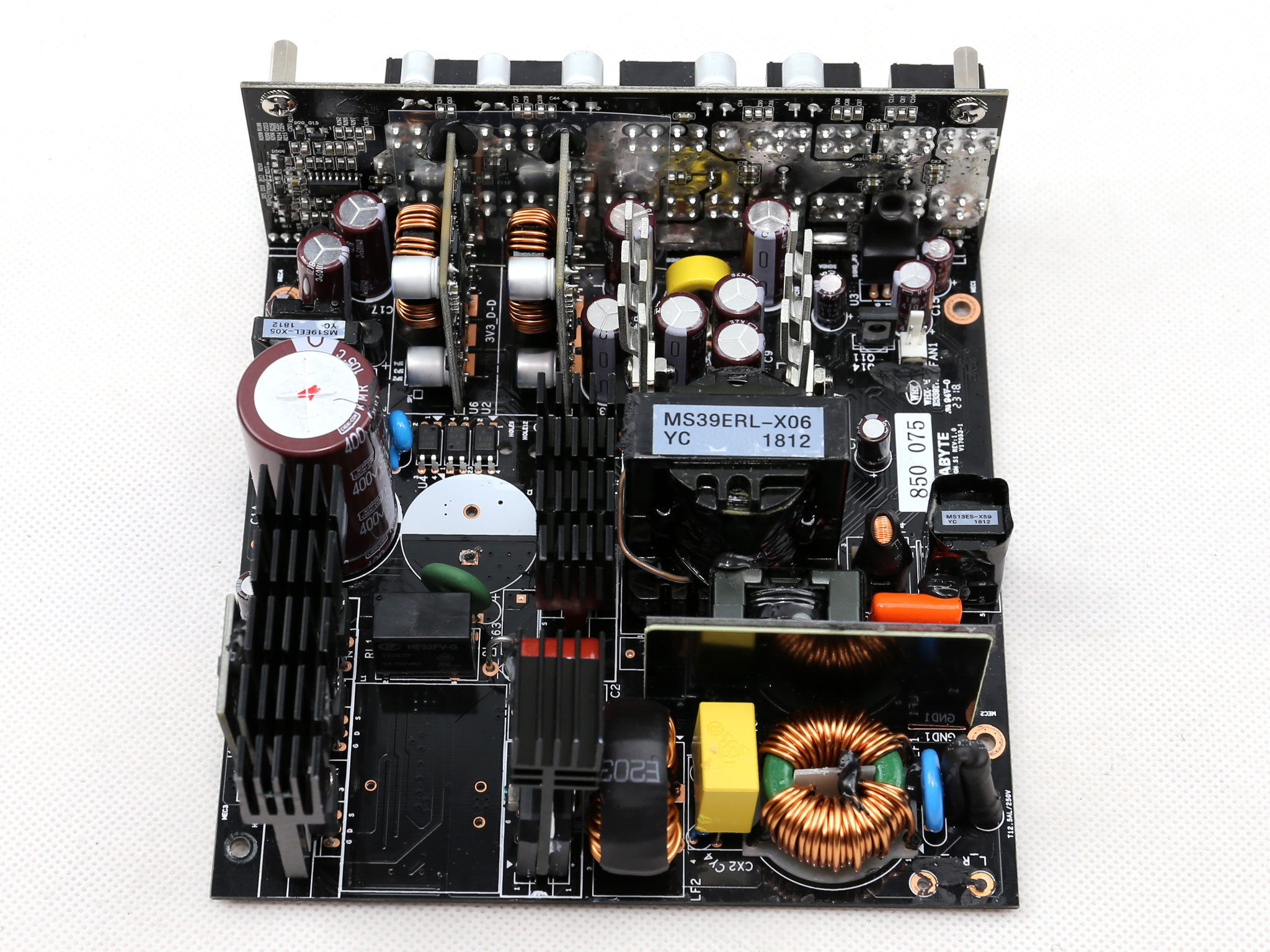
All filtering caps are provided by Chemi-Con, both electrolytic and polymer ones, showing that Gigabyte asked for a very reliable platform. This is also shown by the double ball bearing fan, although Yate Loon is not among the most respectable fan makers nowadays.
Still back in the day the AX1200 used exactly the same fan, with the GP-AP850GM!
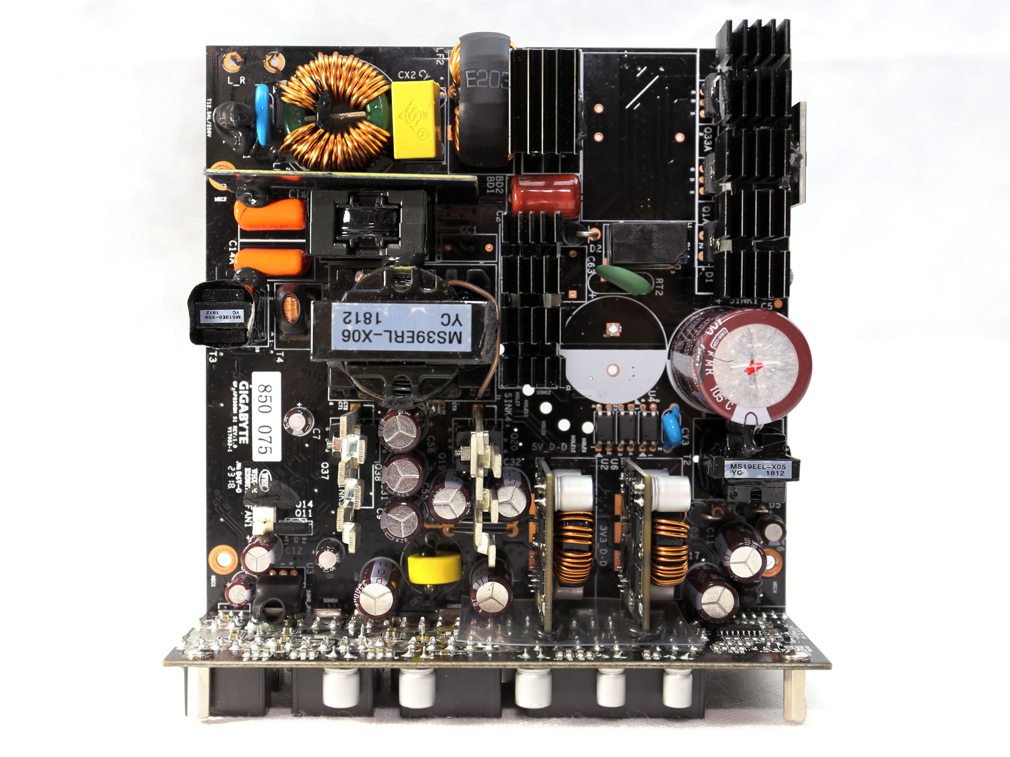
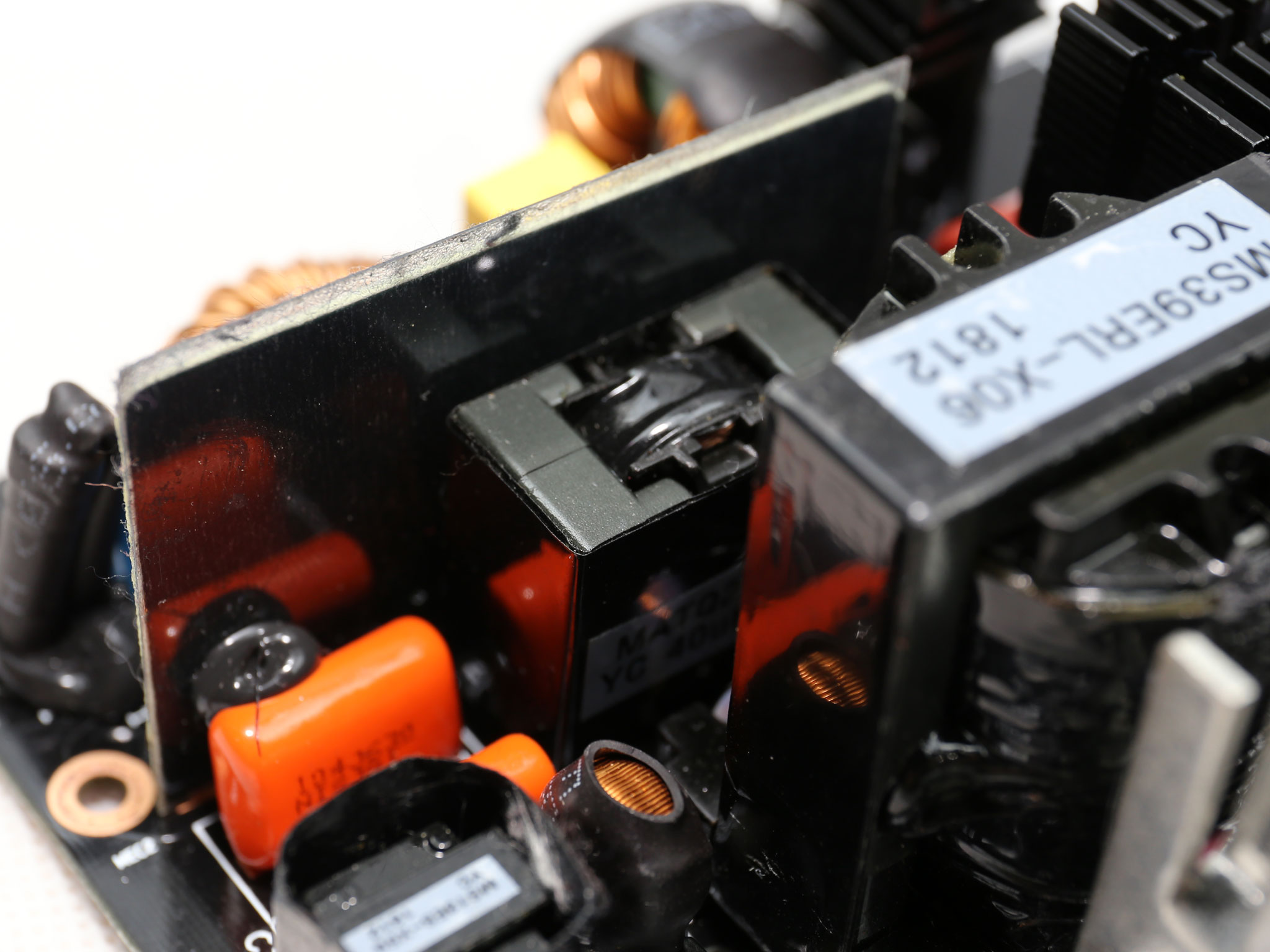
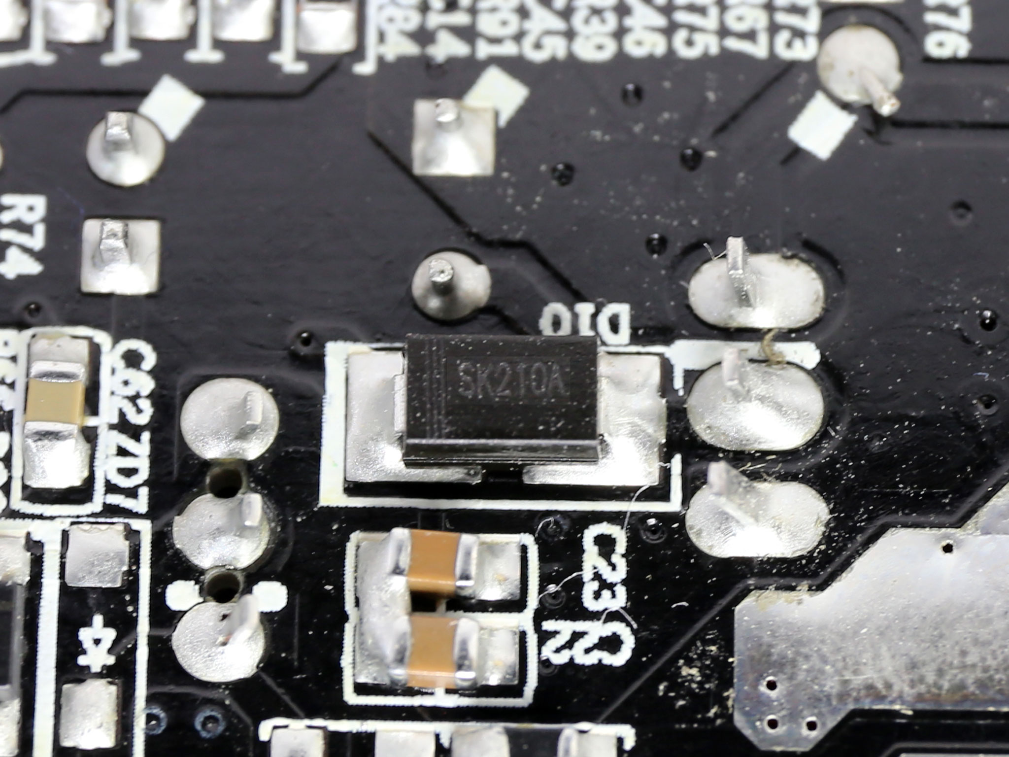
The first part of the transient filter resides on a small PCB and includes one X and two Y caps, along with a CM02X IC, which blocks the X cap's discharge resistors once power is connected. The second part of the EMI filter is on the main PCB and consists of one X and two Y caps, two CM chokes and an MOV (Metal Oxide Varistor).
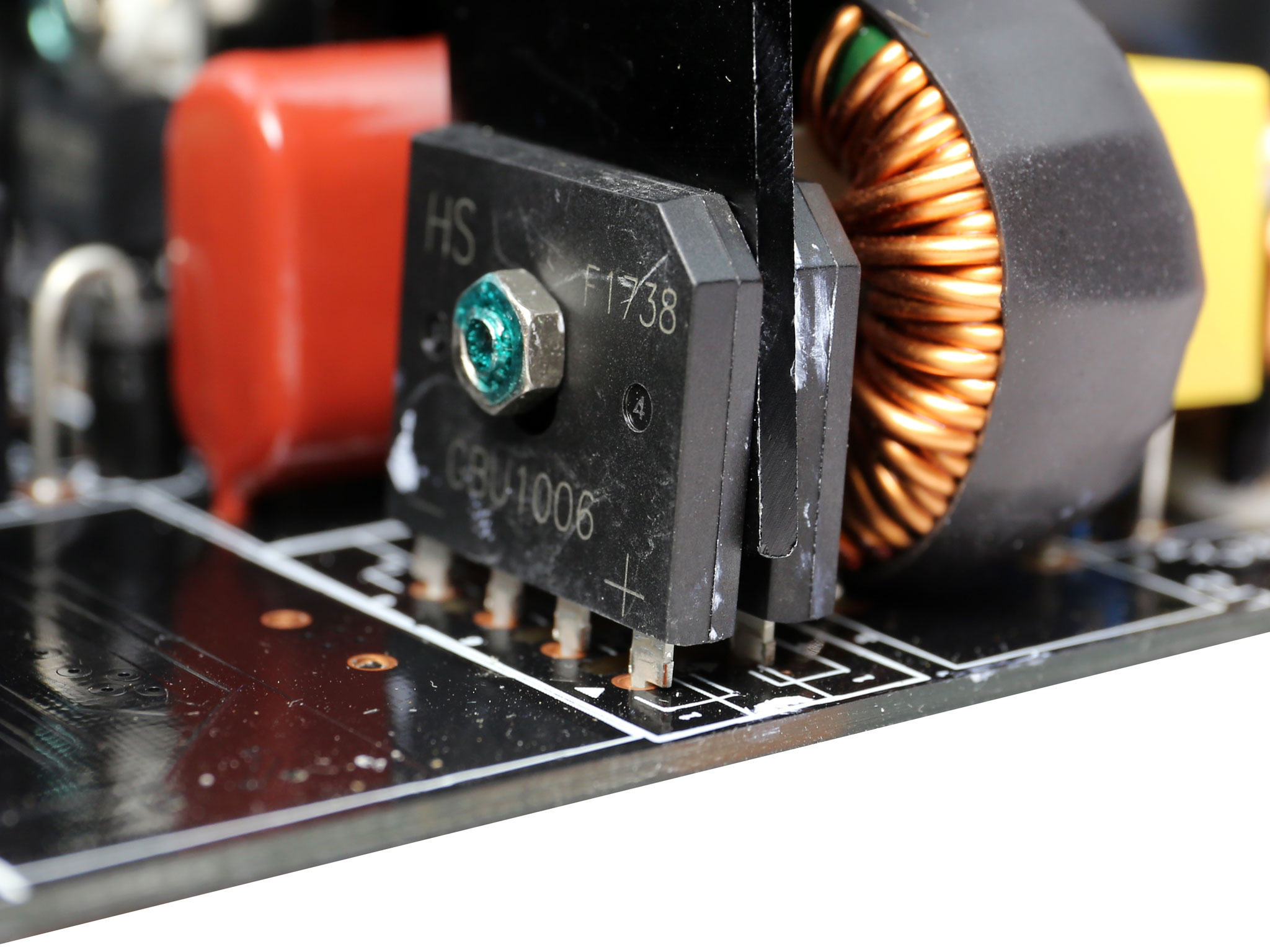
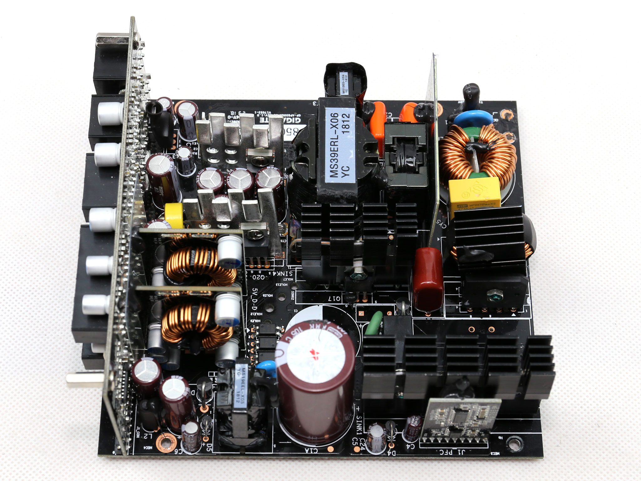
The couple of bridge rectifiers is installed on a leaning heat sink. Combined the pair of GBU1006 rectifiers can handle up to 20 Amps of current.
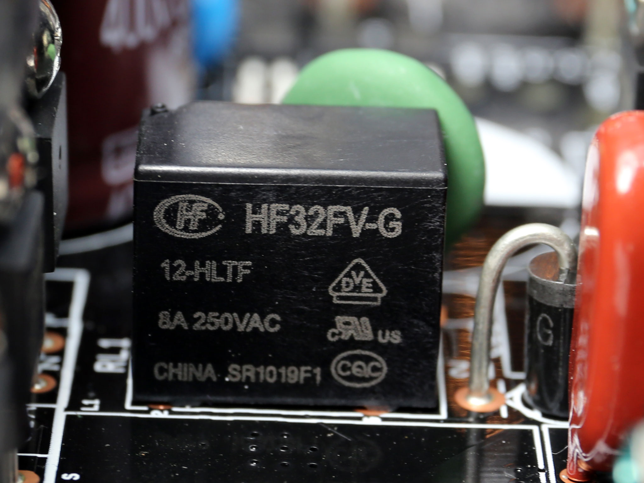
There is an NTC thermistor for protection against large inrush currents, and a bypass relay supports it. We expect to find this relay in every high-end platform since besides a small efficiency boost it also allows the fast cool down of the thermistor, so inrush currents are always kept under control (as long as the used thermistor is up to the task of course).
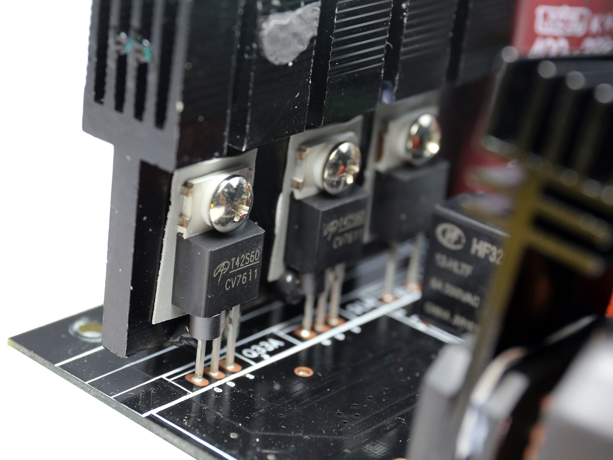
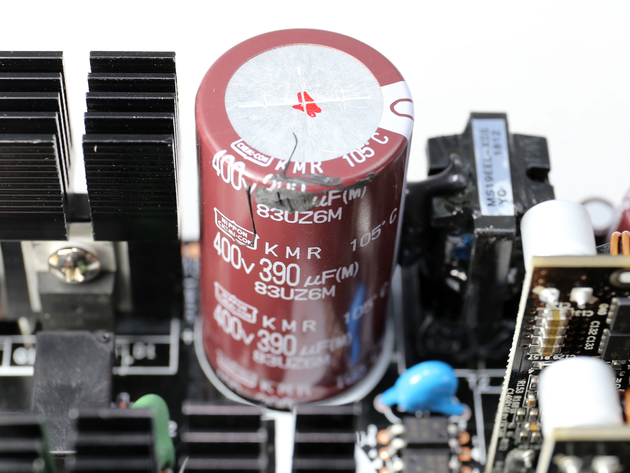
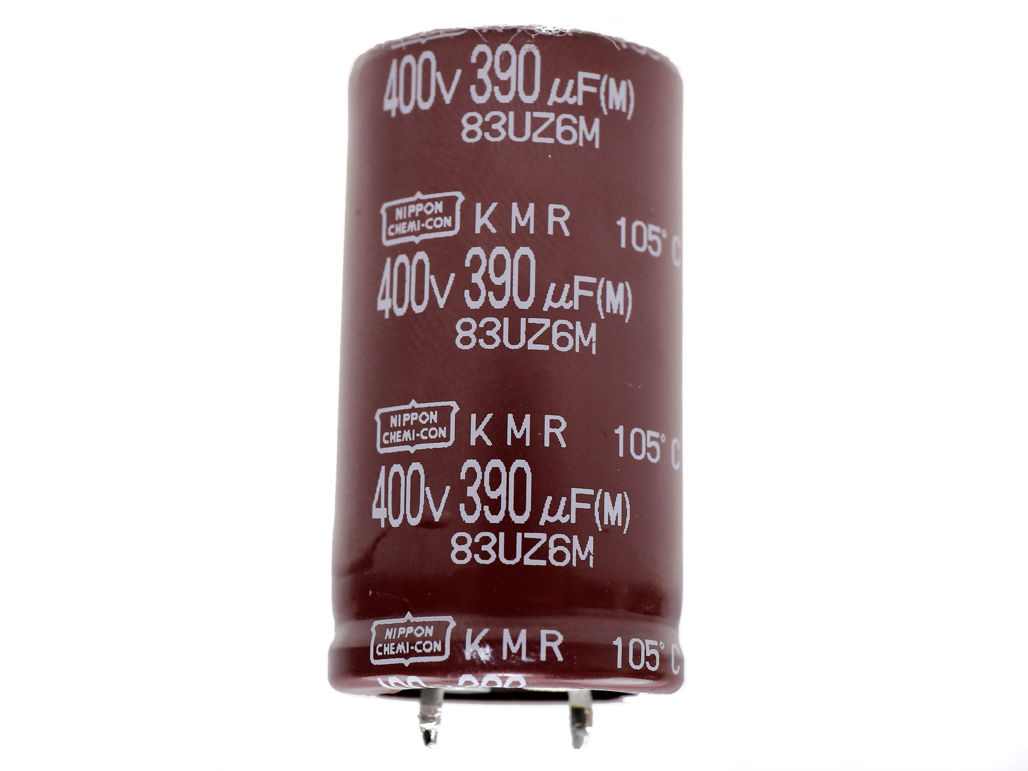
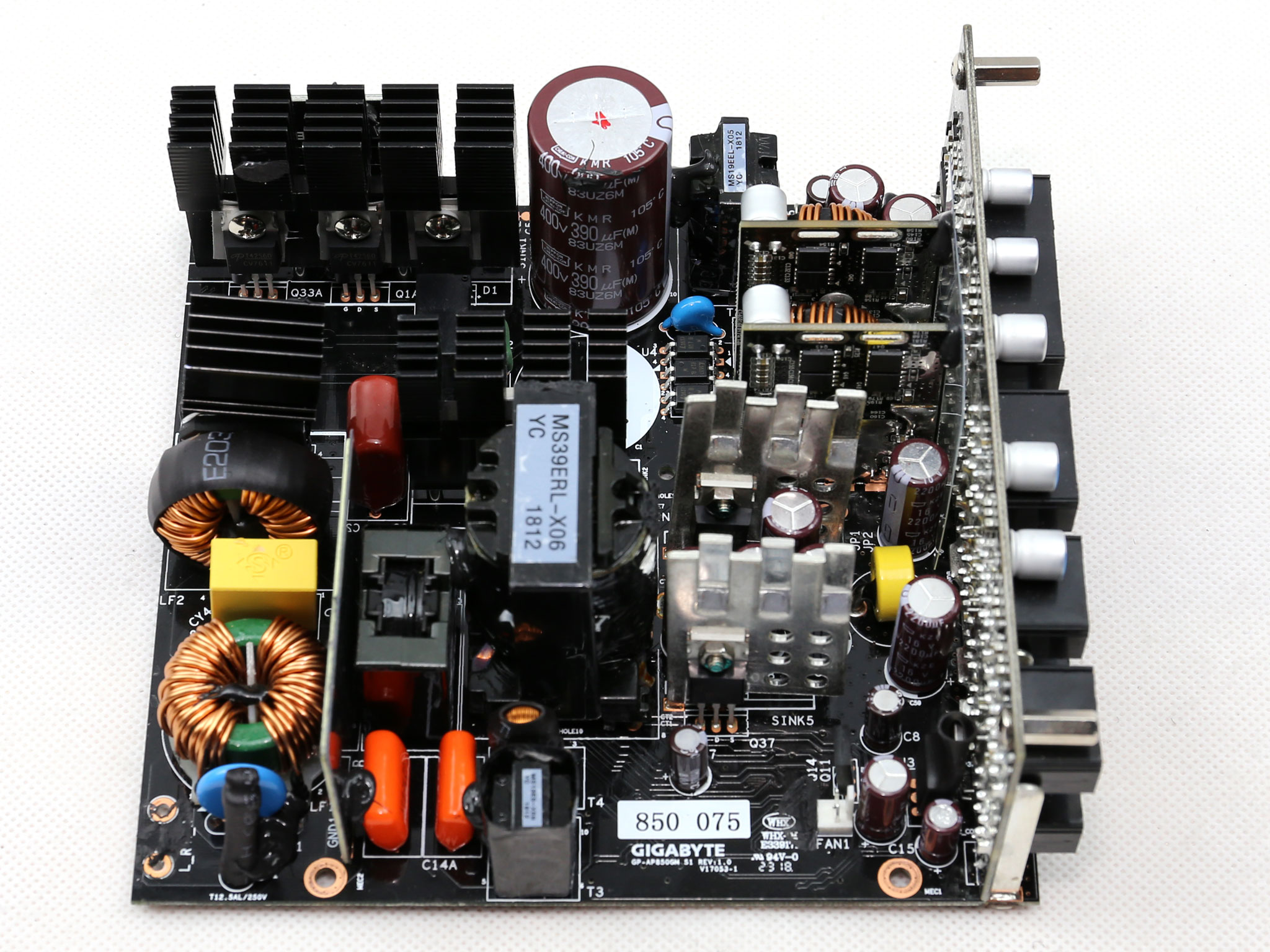
In the APFC converter two Alpha & Omega AOT42S60 FETs are used along with a CREE boost diode. Both bulk caps are provided by Chemi-Con and their combined capacity reaches 780uF, which barely meets the needs of this unit. Apparently MEIC had to use those 390uF caps since the next inline KMR cap has notably larger capacity, at 470uF and there is also the cost difference, since those caps don't come cheap.
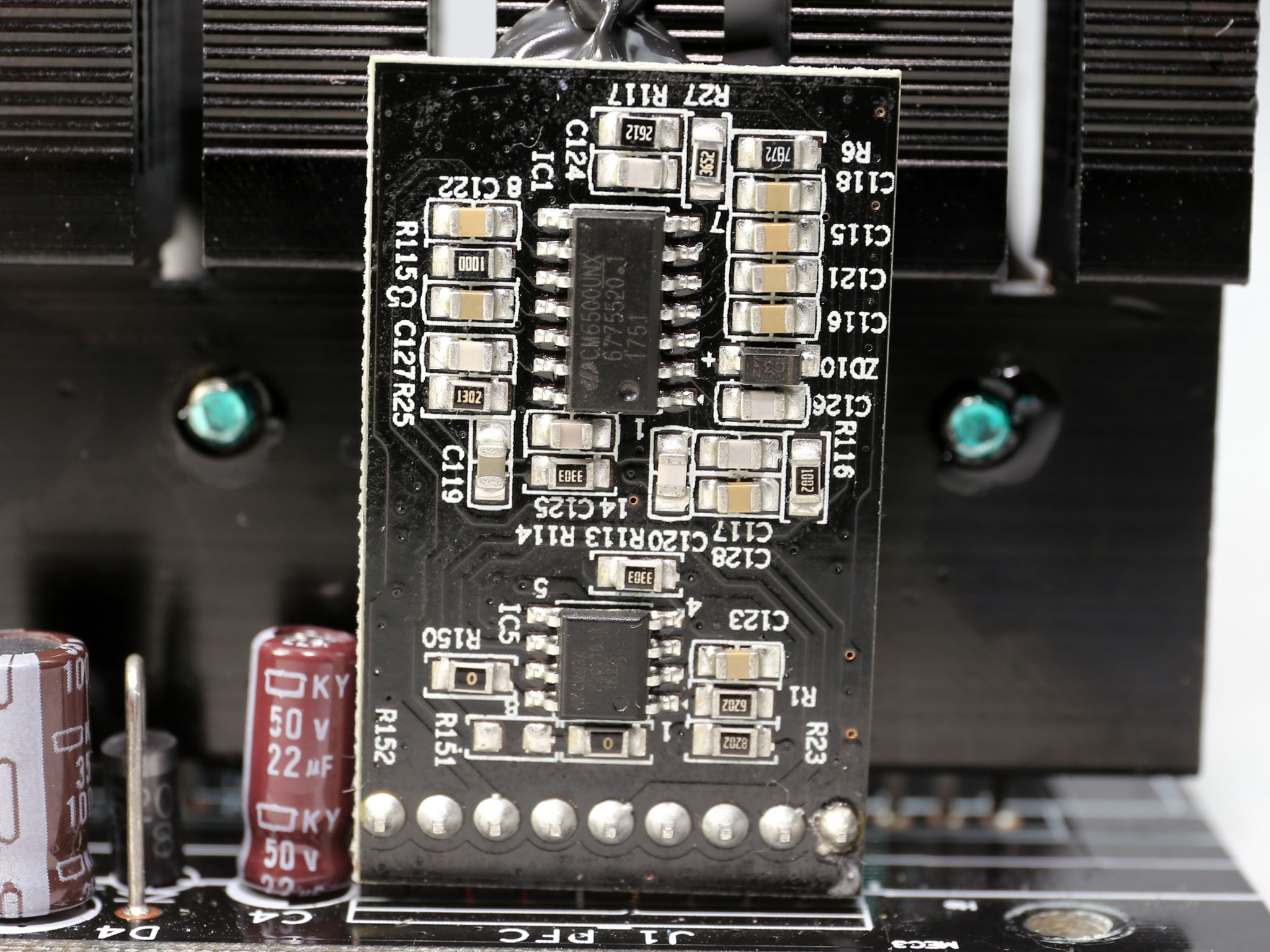
The PFC controller is a Champion CM6500UNX IC, which is supported by a CM03X Green PFC controller that lowers power consumption in standby mode. Both are installed onto a small vertical board.
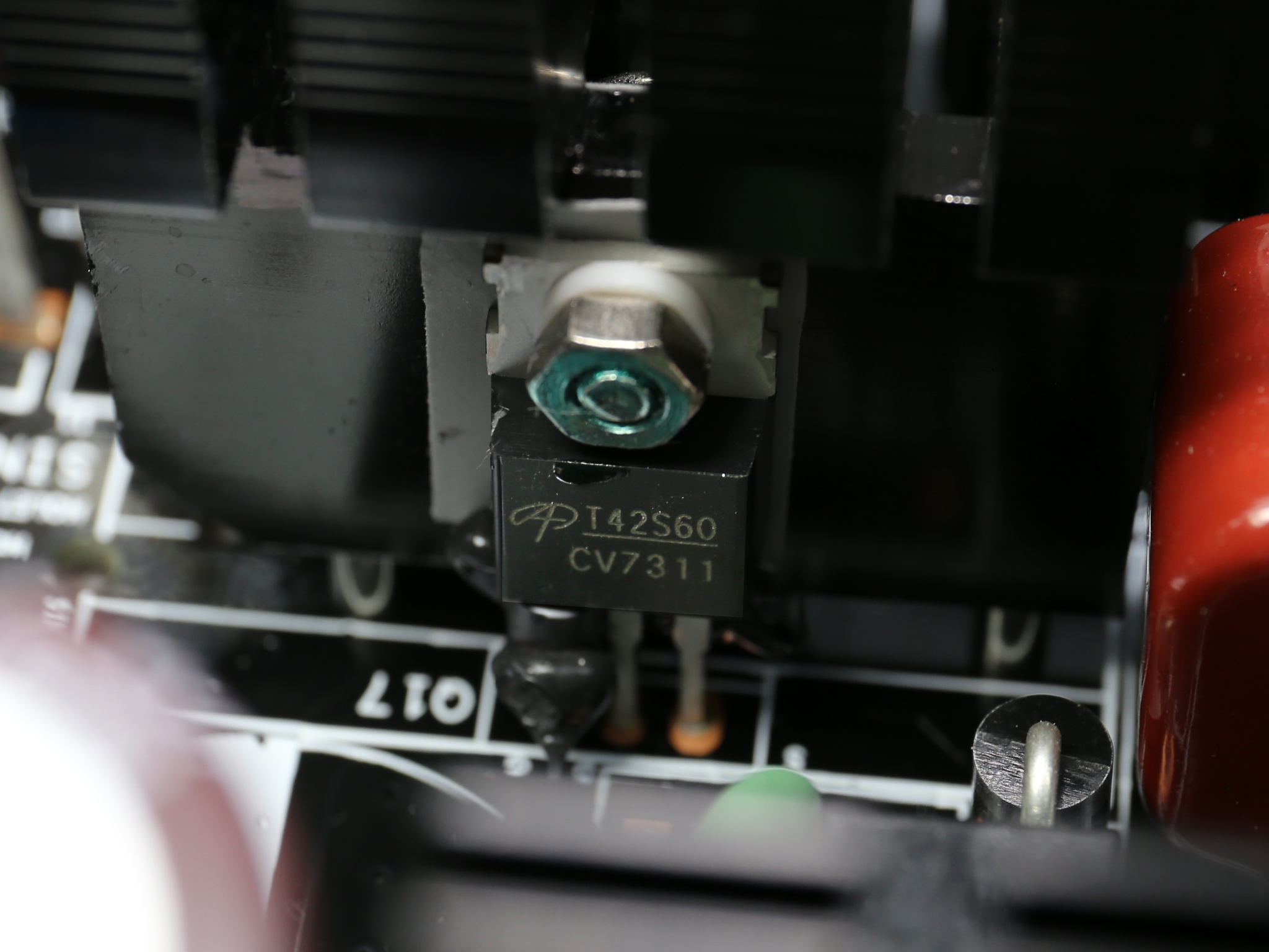
The primary FETs, a pair of Alpha & Omega AOT42S60, are arranged in a half-bridge topology.
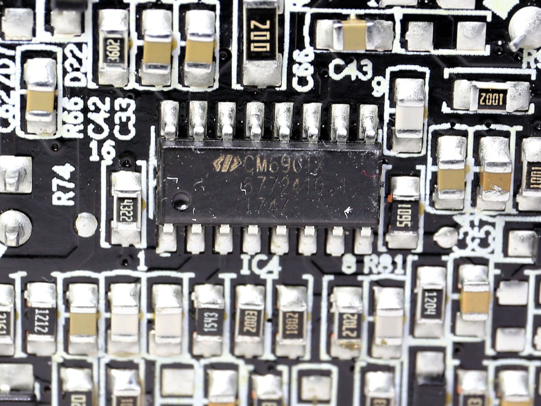
The LLC resonant controller is a Champion CM6901. This controller is heavily used in high efficiency PSUs.
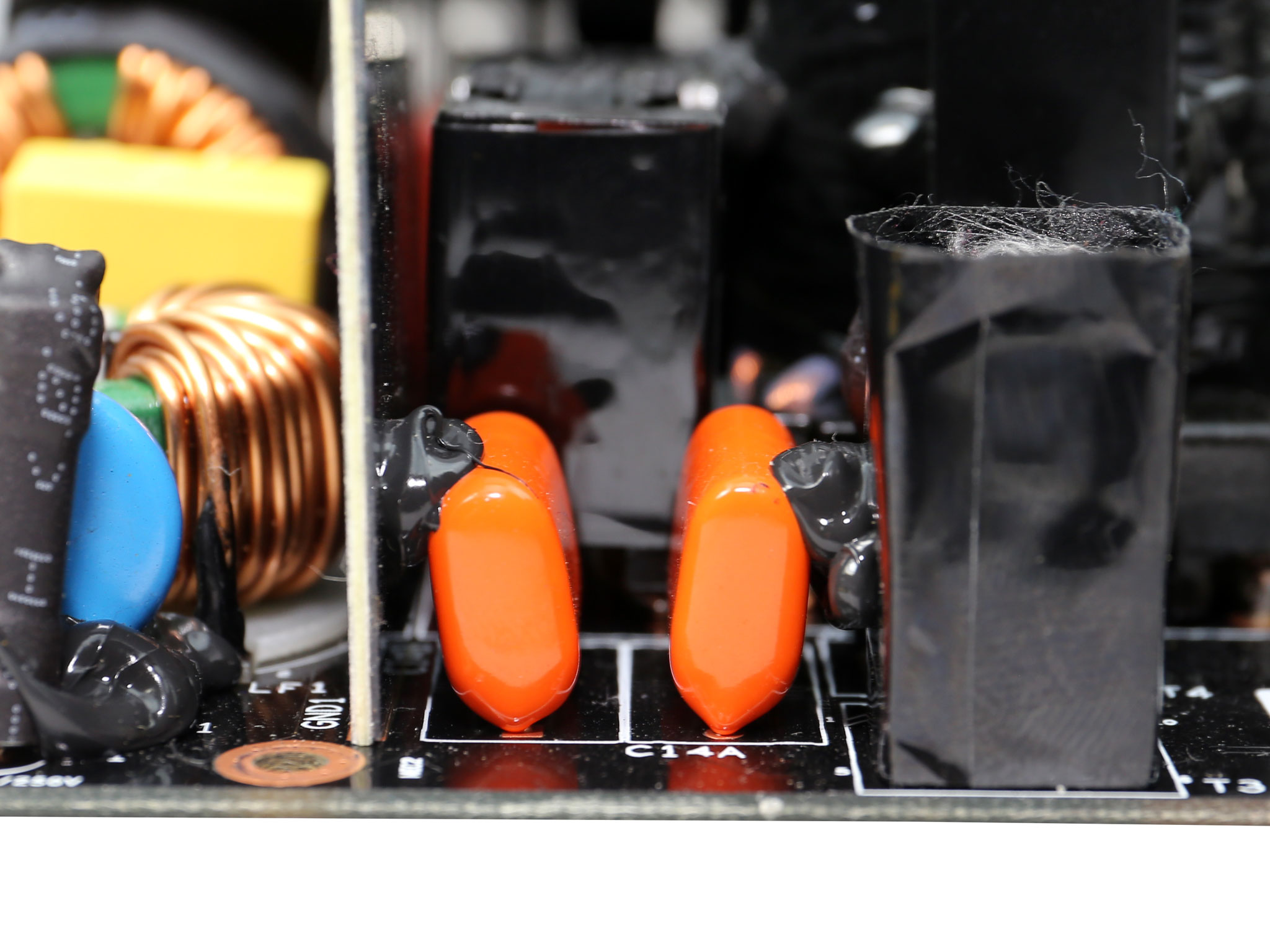
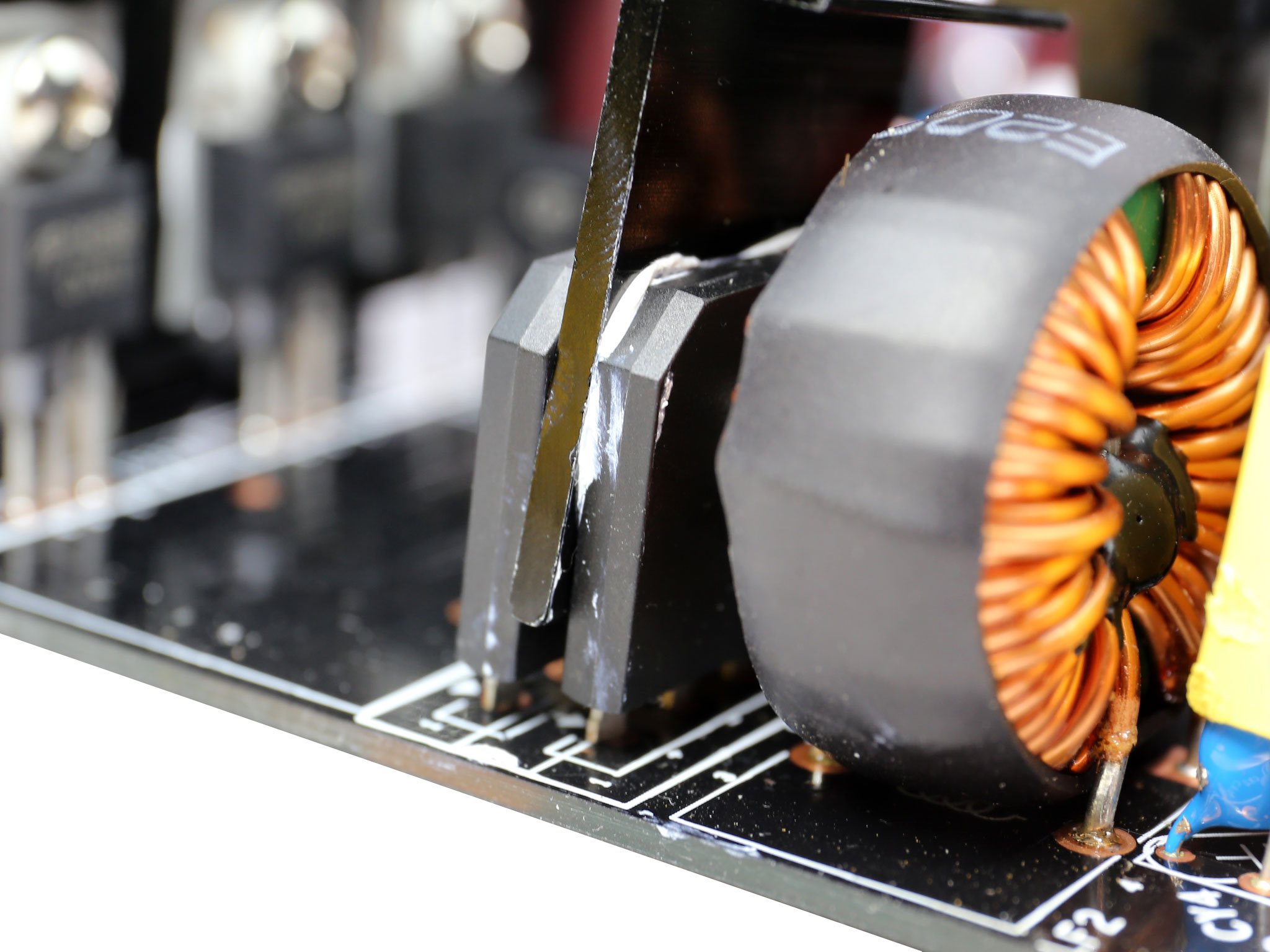
The main transformer of the unit. Right next to it is the resonant tank and the capacitive components of the LLC resonant converters, a couple of X caps. There is also a shield between the transient filter and the resonant tank, providing protection against radiated EMI.

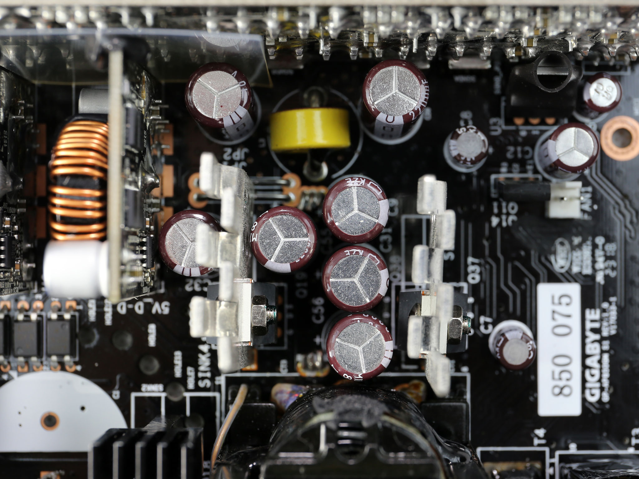
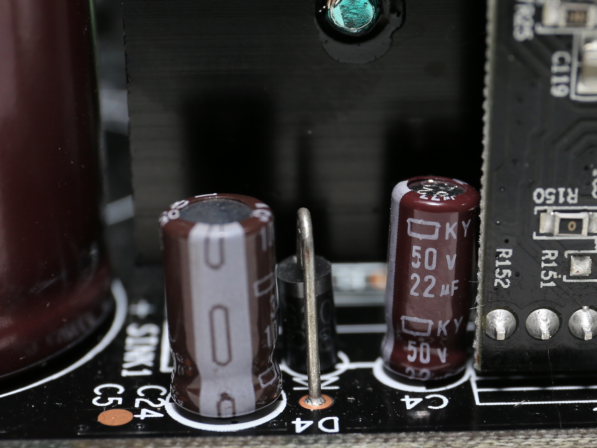
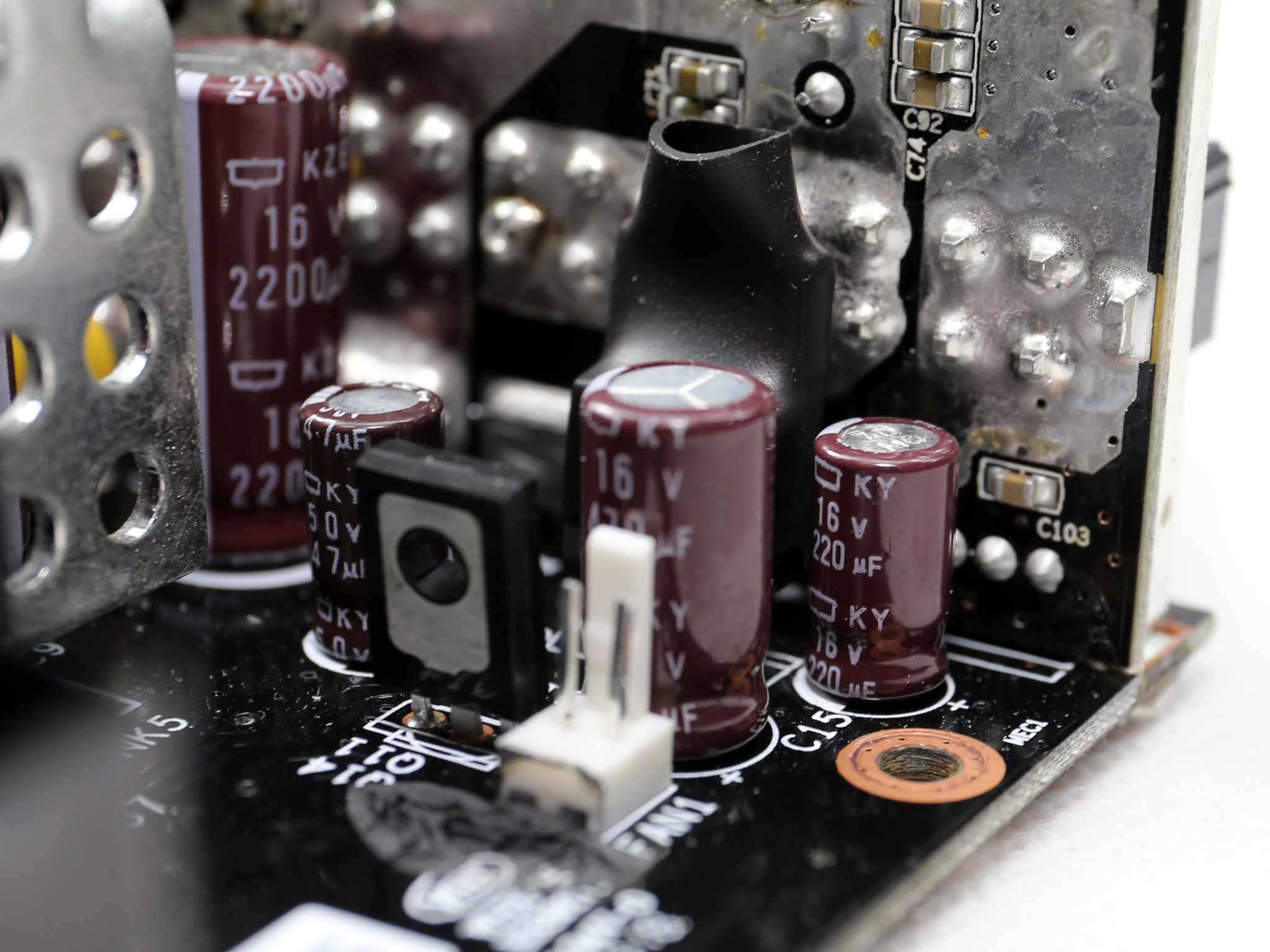
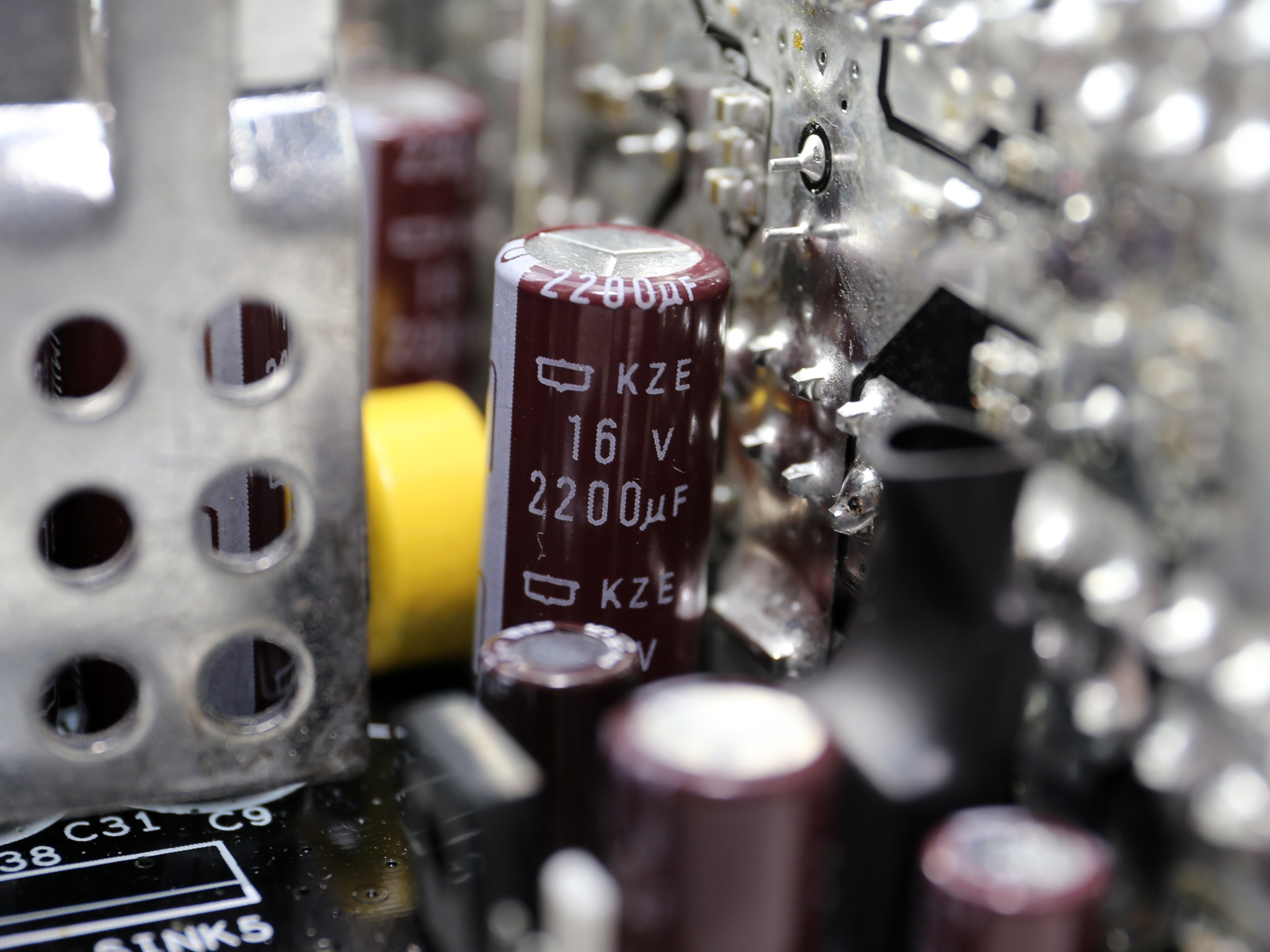
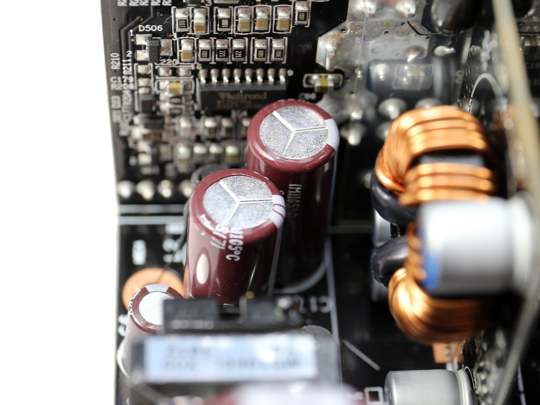
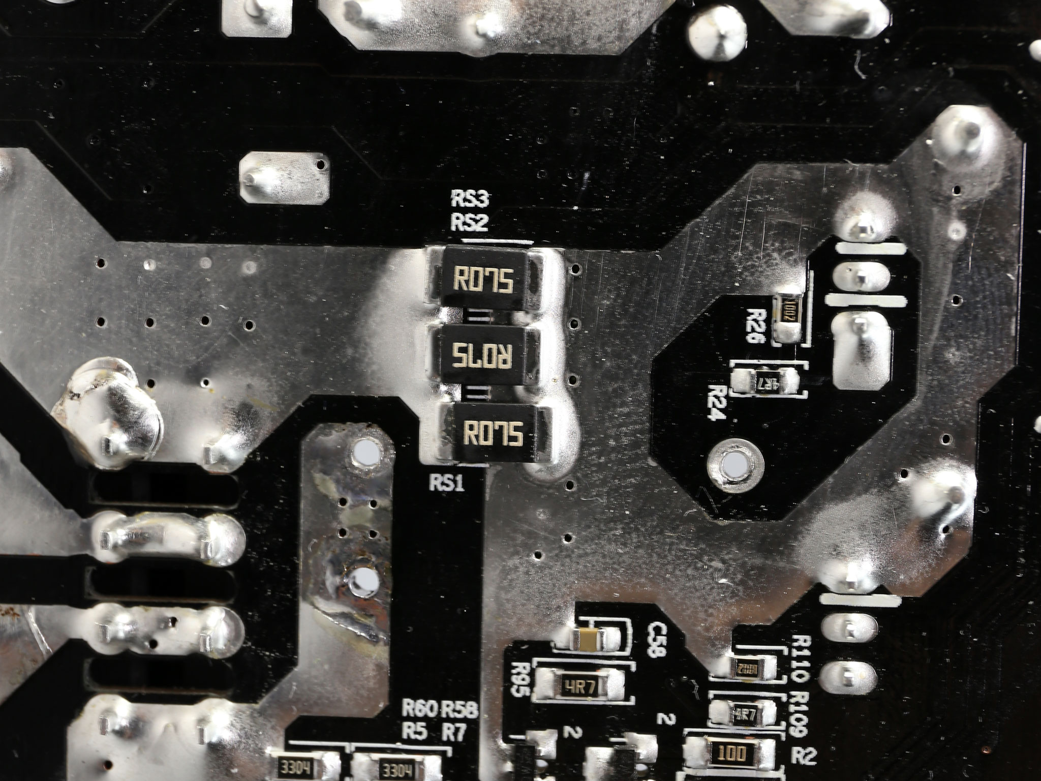
The +12V rail is regulated by four Alpha & Omega AOT2142L FETs. The filtering caps are by Chemi-Con and belong to the KZE and KY lines, which are popular in high-end PSUs.
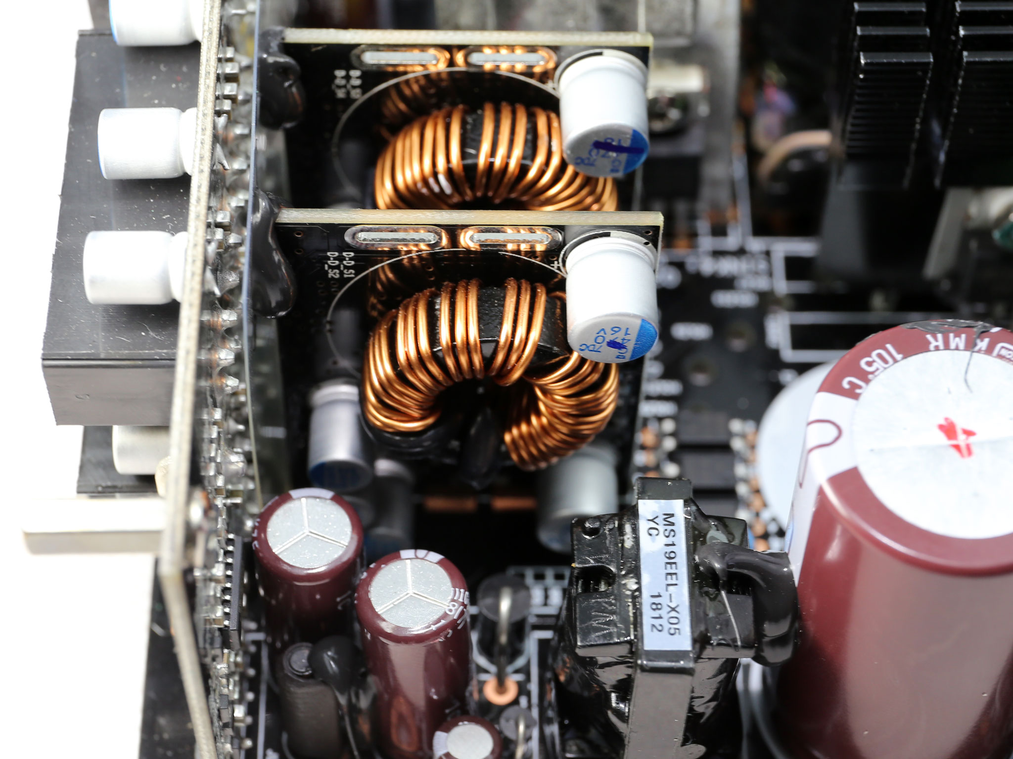
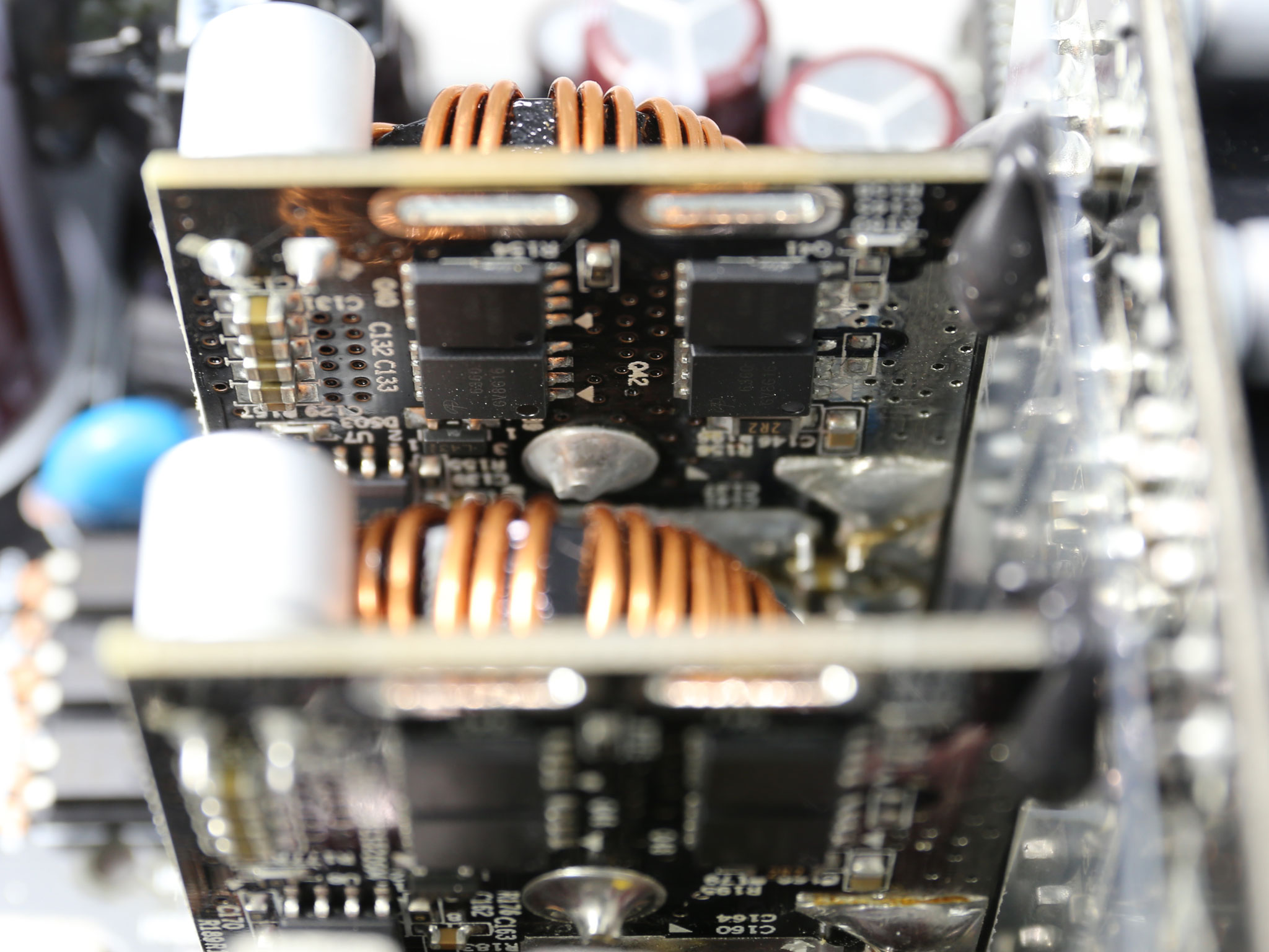
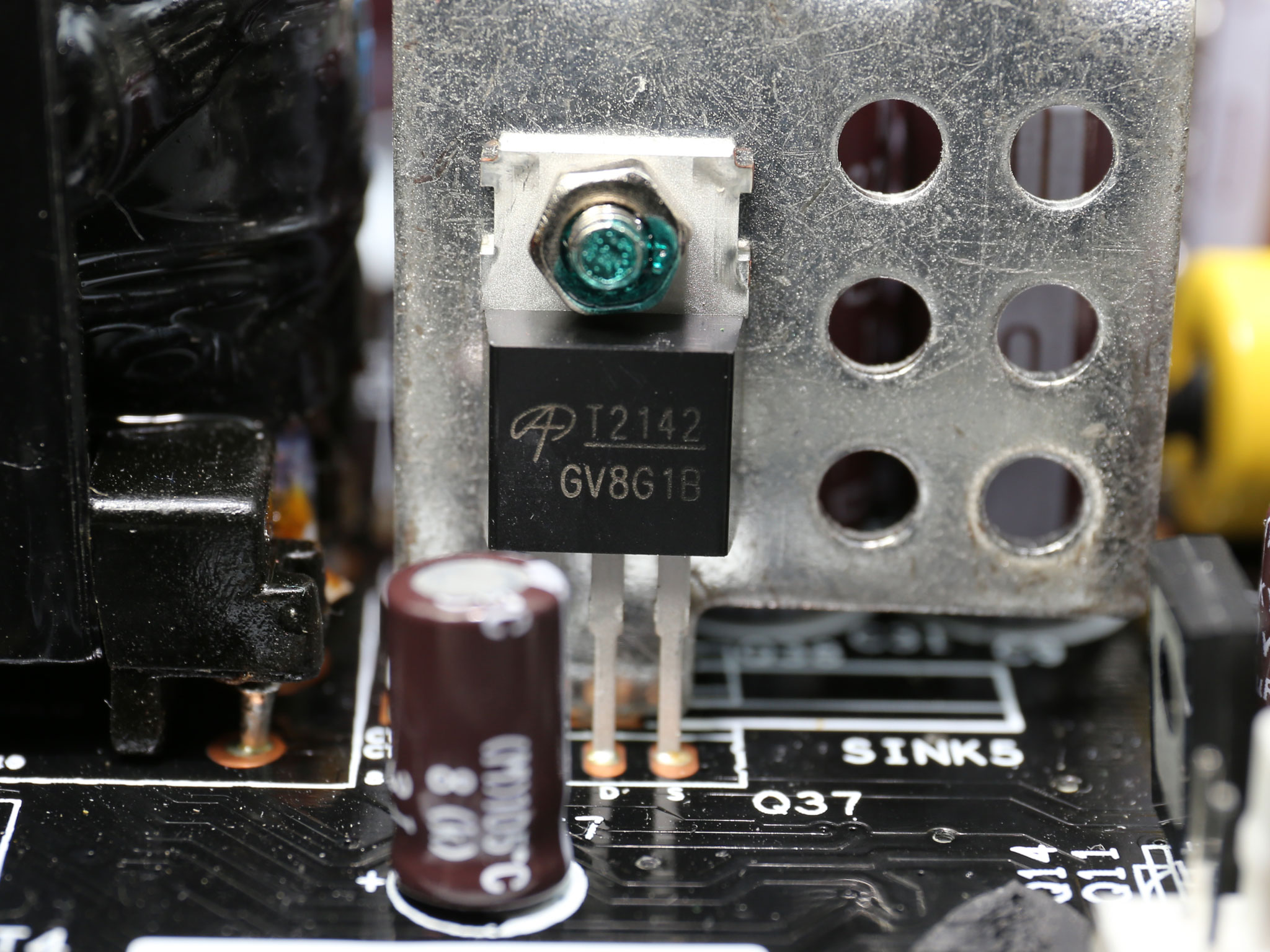
The minor rails are generated through a couple of voltage regulation modules (VRMs). Each of them uses four GV8G16 FETs and a NCP1587 PWM controller.
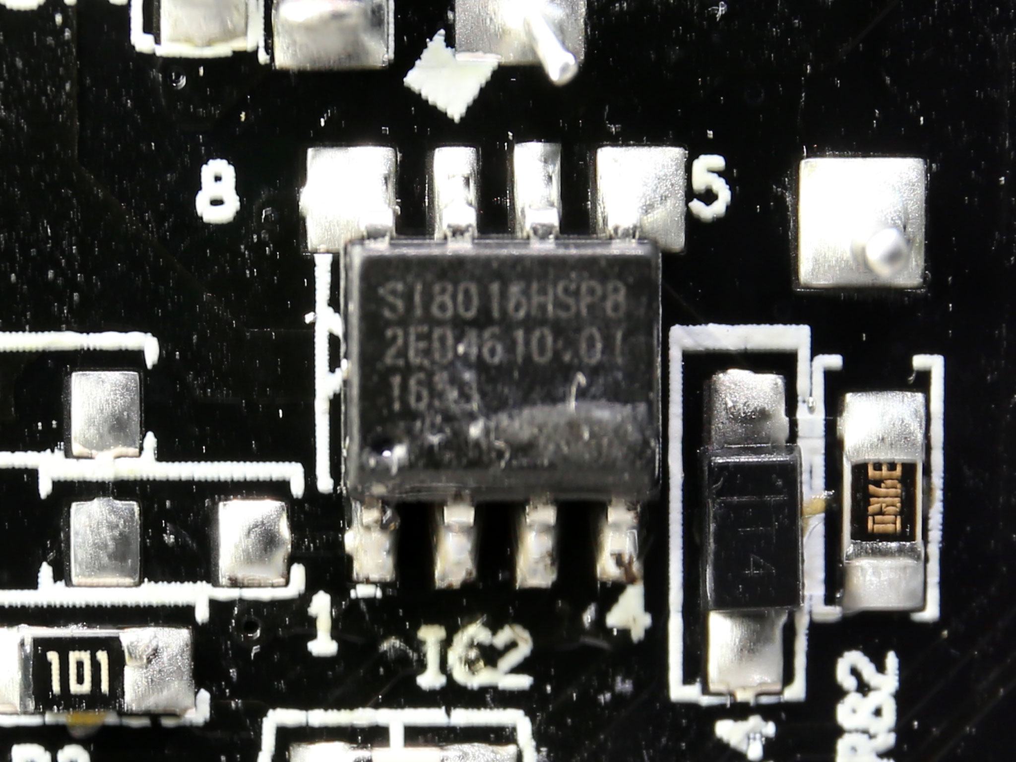
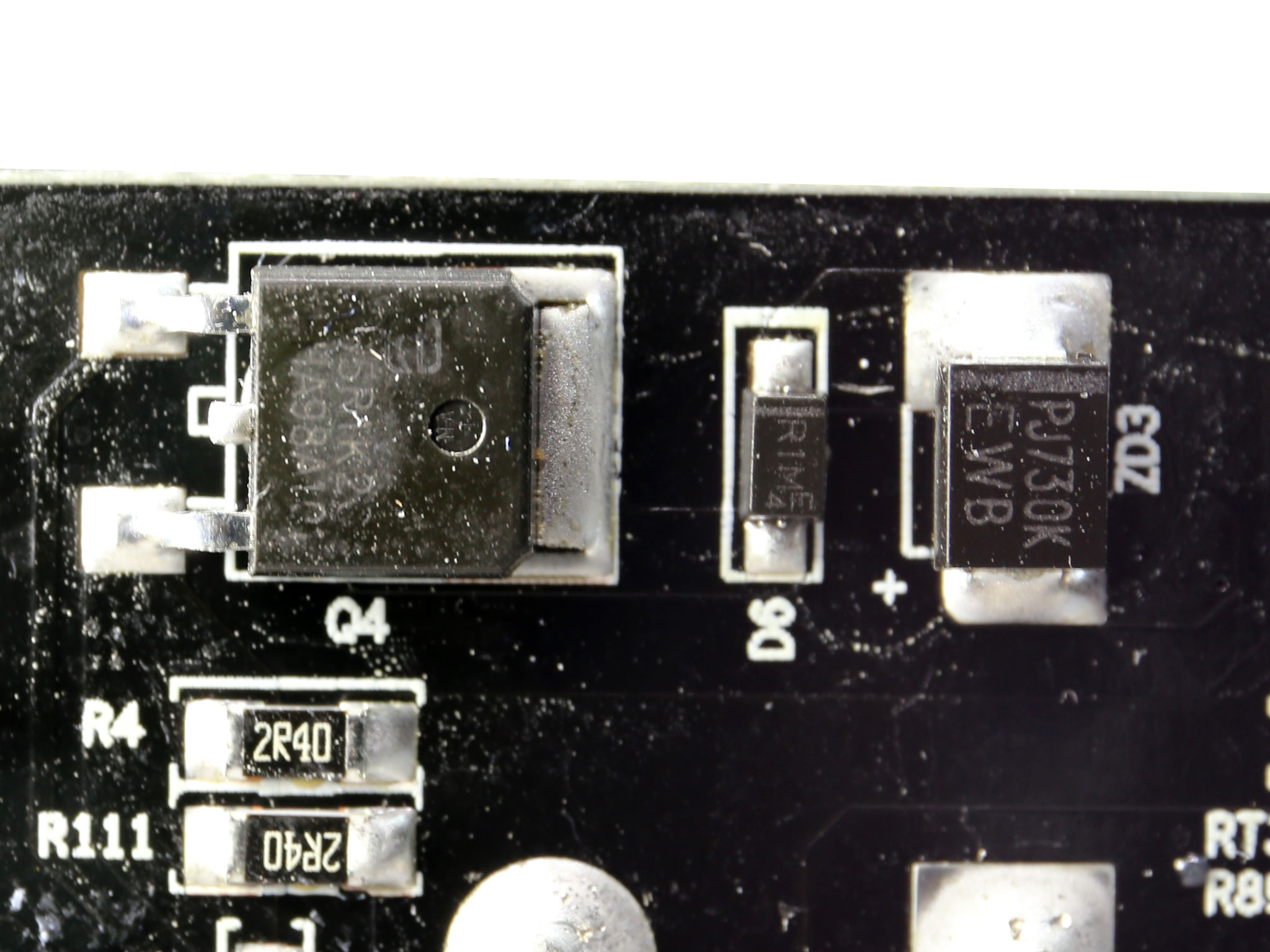
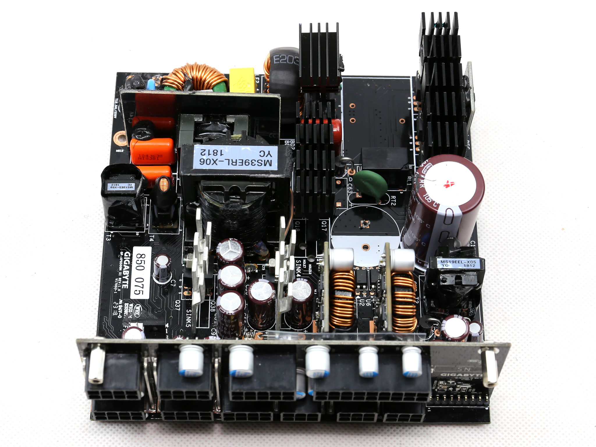
The standby PWM controller (SI8016HSP8) is installed on the solder side of the PCB and its primary switching FET, TPD65R1K2C, is close by.
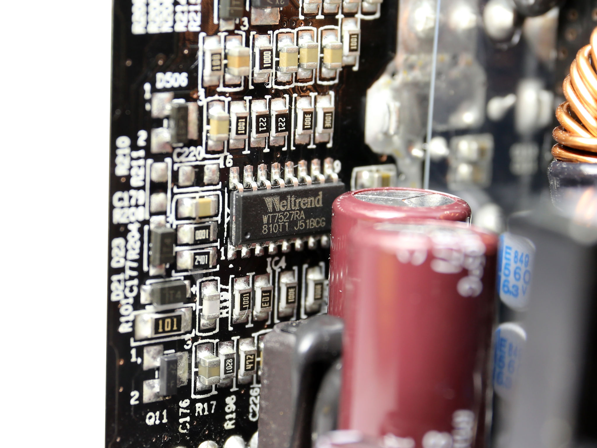
The PSU's protections handles a Weltrend WT7527A IC, located at the back side of the modular board. This IC also has over current protection for up to two +12V rails, besides the minor ones.
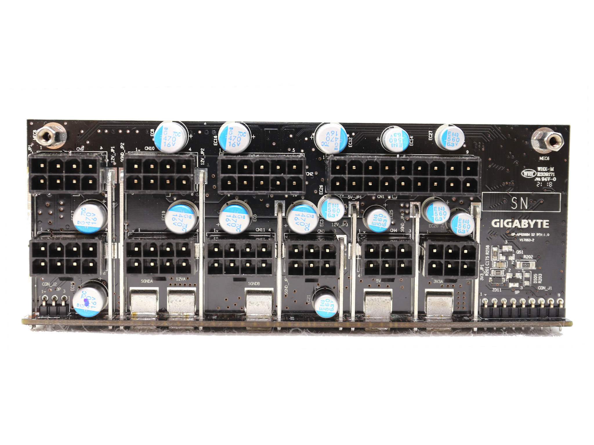
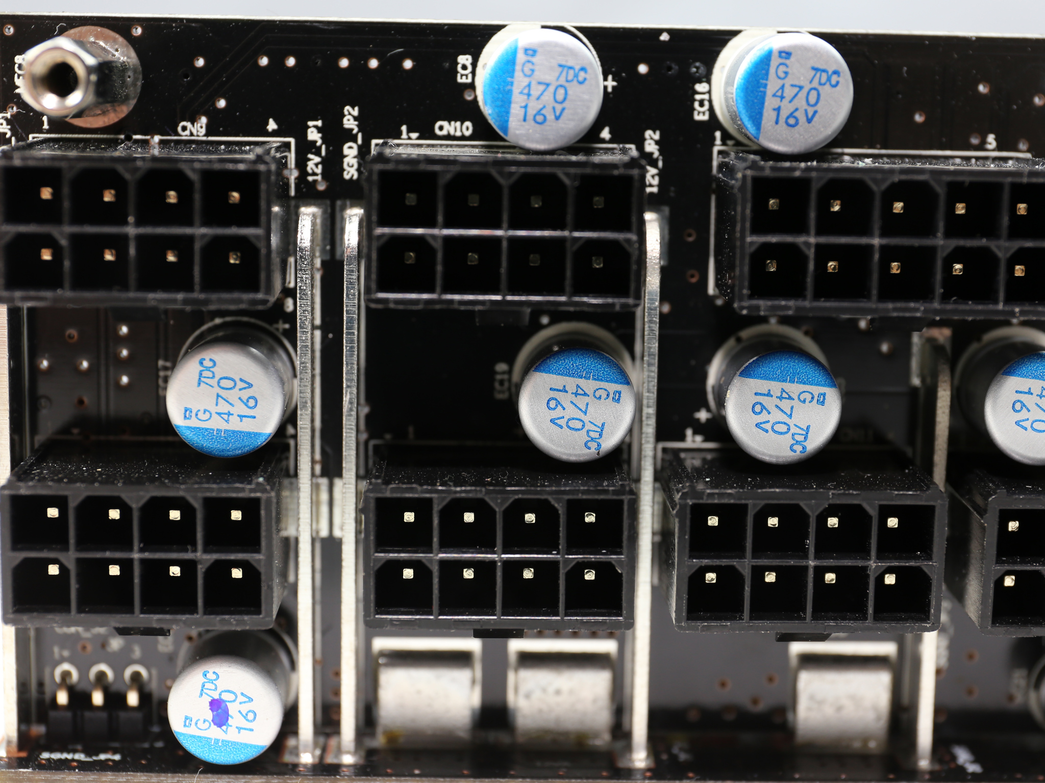
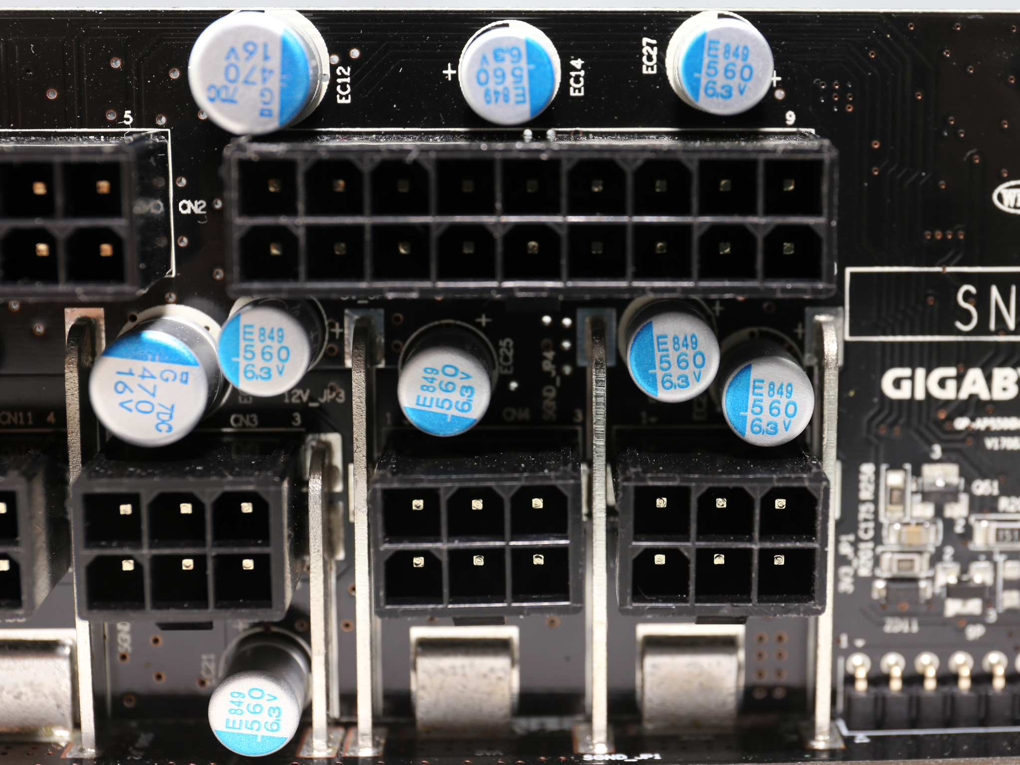
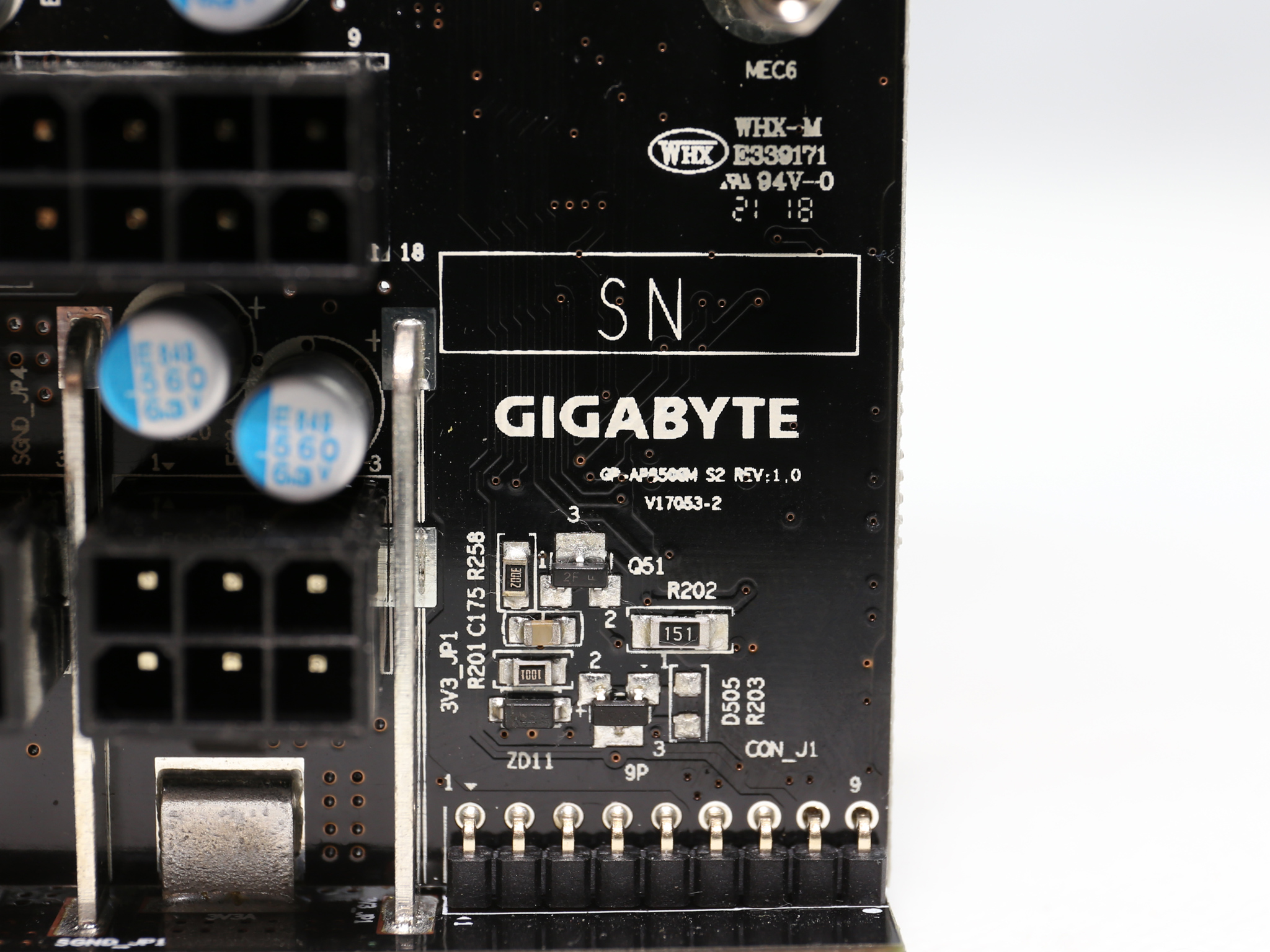
At the front side of the modular PCB, which is connected to the main board through a number of bus bars, a number of polymer Chemi-Con caps provides an extra ripple suppression layer.
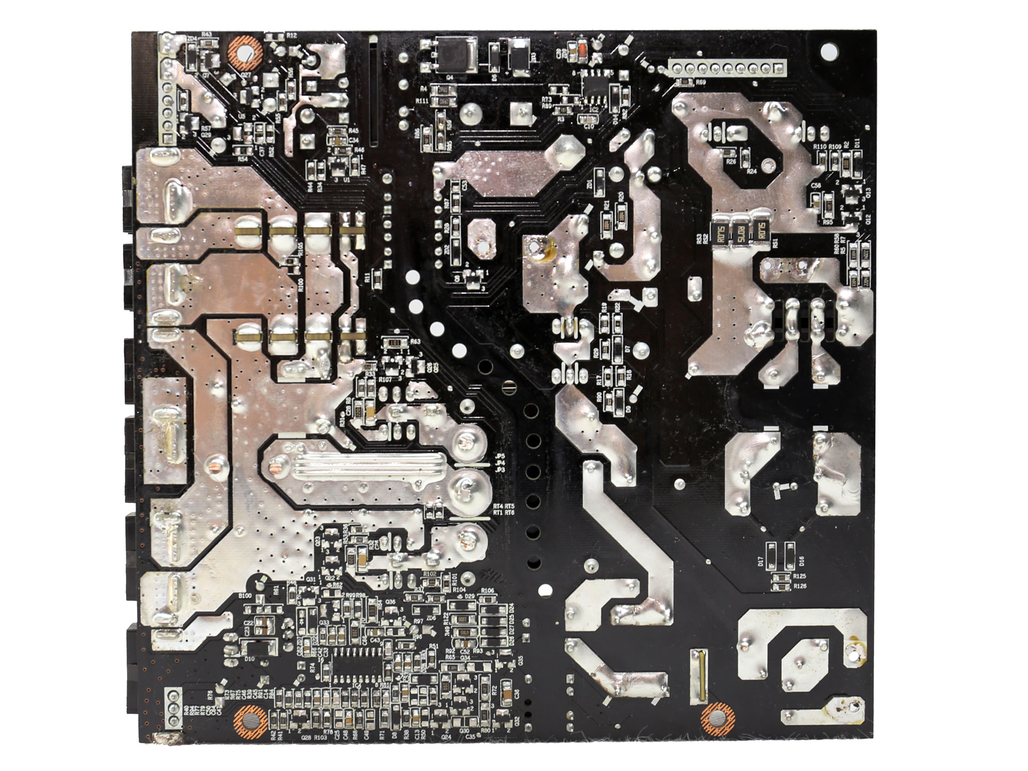
The soldering quality on the main PCB is quite good. We also noticed that in our sample at least the solder most likely contains lead, since it was quite easy to desolder parts. In our opinion lead-free solder although it is supposed to be more environmental friendly, in the end it does more damage because of the increased number of failures in the devices that use it.
Lead-free solder joints crack easier and on top of that, the higher temperatures required by this type of solder can damage sensitive components. Tin whiskers are also a problem.
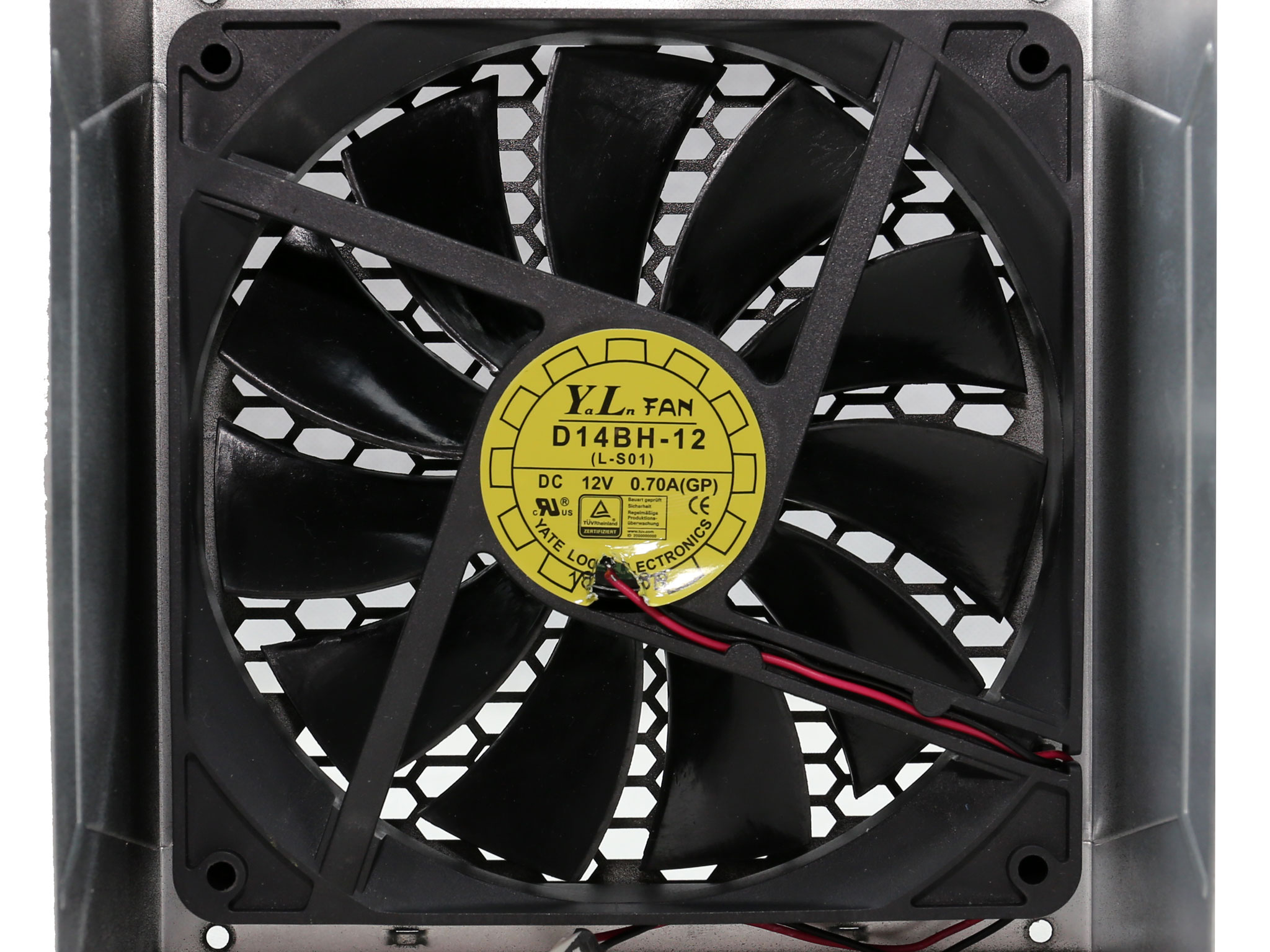
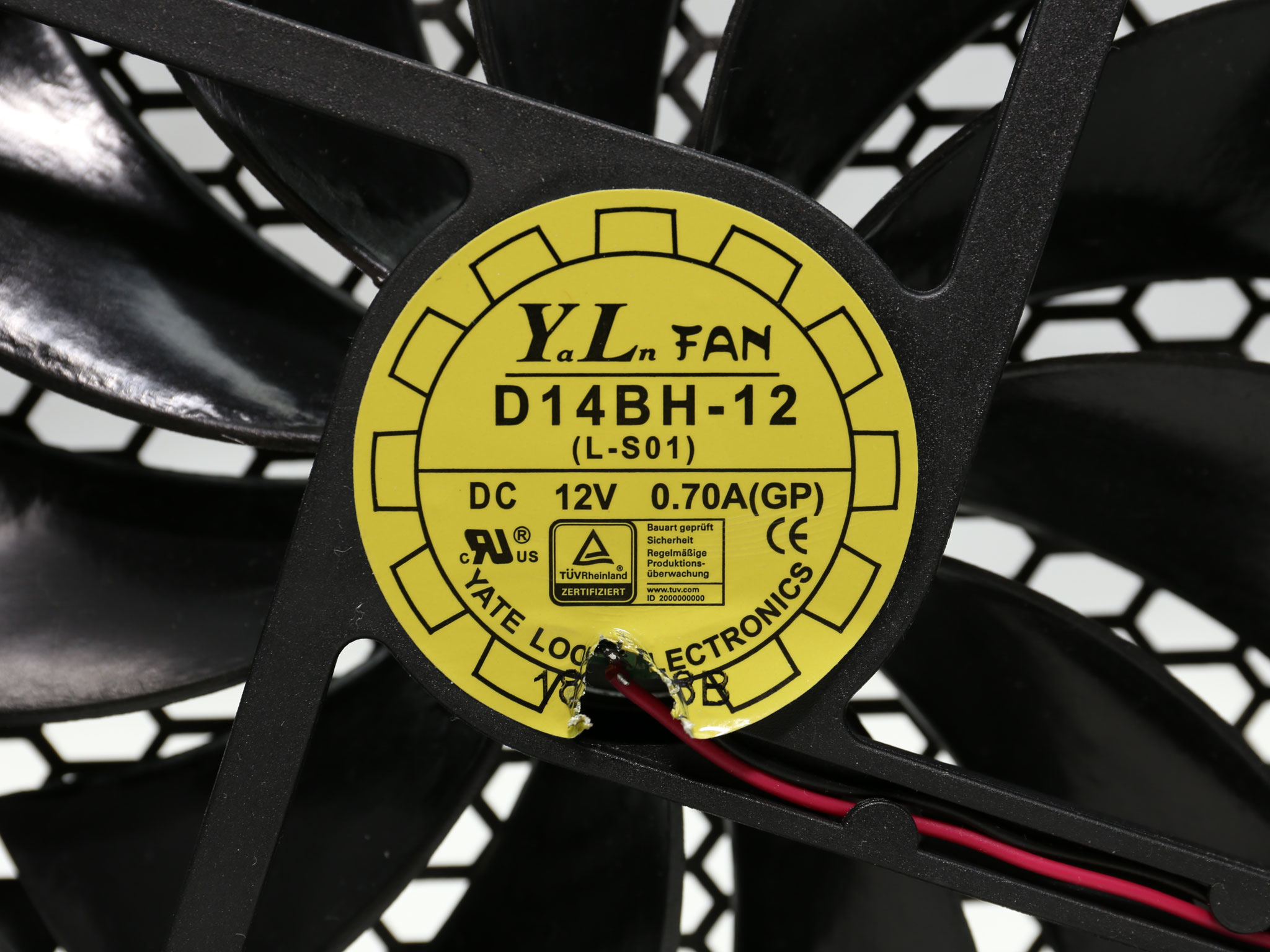
The cooling fan is provided by Yate Loon (D14BH-12) and it is very strong for a 850W and highly efficient platform like this one. It uses double ball bearings meaning that it won't have a problem operating under tough conditions. The fan profile is not aggressive, so under normal operation the PSU will be silent.
To learn more about our PSU tests and methodology, please check out How We Test Power Supply Units.
Primary Rails And 5VSB Load Regulation
Load Regulation testing is detailed here.

Hold-Up Time
Our hold-up time tests are described in detail here.

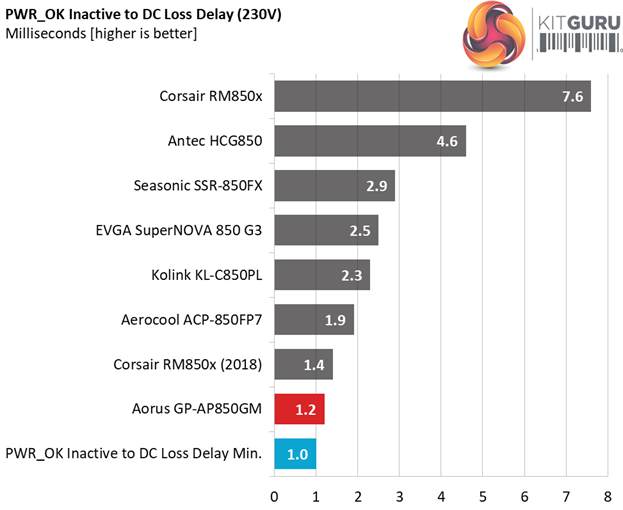
The oscilloscope screenshots that we took during the hold-up time measurements:
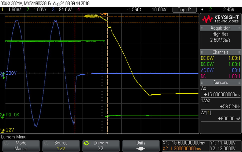
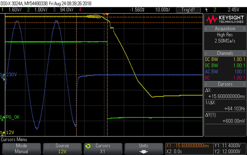
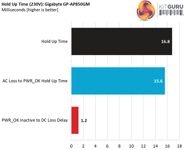
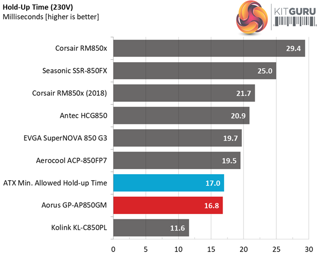
The hold-up time is only a hair away from what the ATX spec requires (17ms) and the power ok signal is close as well to 16ms.
Inrush Current
For details on our inrush current testing, please click here.
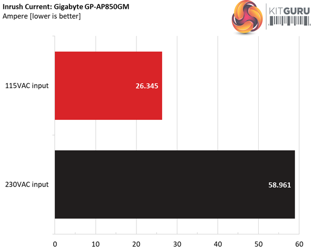
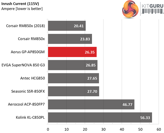
The inrush current is low with 115V and a little higher than the normal with 230V.
Load Regulation And Efficiency Measurements
The first set of tests reveals the stability of the voltage rails and the GP-AP850GM’s efficiency. The applied load equals (approximately) 10 to 110 percent of the power supplies maximum load in increments of 10 percentage points.
We conducted two additional tests.
During the first, we stressed the two minor rails (5V and 3.3V) with a high load, while the load at +12V was only 0.1A. This test reveals whether a power supply is compatible with Intel’s C6/C7 sleep states or not. In the second test, we determined the maximum load the +12V rail could handle with minimal load on the minor rails.
| Test # | 12V | 5V | 3.3V | 5VSB | DC/AC (Watts) | Efficiency | Fan Speed (RPM) | PSU Noise (dB[A]) | Temps (In/Out) | PF/AC Volts |
| 1 | 5.159A | 1.968A | 1.942A | 0.978A | 84.888 | 85.923% | 0 | <6.0 | 46.65°C | 0.963 |
| 12.267V | 5.083V | 3.398V | 5.114V | 98.796 | 40.33°C | 115.12V | ||||
| 2 | 11.298A | 2.959A | 2.920A | 1.176A | 169.342 | 89.404% | 532 | 14.2 | 40.77°C | 0.983 |
| 12.254V | 5.071V | 3.388V | 5.101V | 189.413 | 49.04°C | 115.11V | ||||
| 3 | 17.828A | 3.455A | 3.399A | 1.376A | 254.476 | 90.768% | 590 | 17.0 | 41.18°C | 0.989 |
| 12.255V | 5.064V | 3.382V | 5.089V | 280.358 | 51.70°C | 115.11V | ||||
| 4 | 24.374A | 3.955A | 3.907A | 1.576A | 339.688 | 91.208% | 765 | 24.2 | 41.91°C | 0.987 |
| 12.246V | 5.058V | 3.378V | 5.077V | 372.432 | 53.10°C | 115.11V | ||||
| 5 | 30.606A | 4.948A | 4.894A | 1.777A | 425.015 | 90.992% | 860 | 27.9 | 42.12°C | 0.986 |
| 12.237V | 5.051V | 3.371V | 5.064V | 467.092 | 54.28°C | 115.35V | ||||
| 6 | 36.778A | 5.950A | 5.883A | 1.980A | 509.536 | 90.642% | 1075 | 33.7 | 42.67°C | 0.988 |
| 12.228V | 5.044V | 3.366V | 5.051V | 562.141 | 55.19°C | 115.11V | ||||
| 7 | 43.028A | 6.950A | 6.876A | 2.184A | 594.873 | 90.139% | 1255 | 37.8 | 43.30°C | 0.989 |
| 12.219V | 5.037V | 3.360V | 5.038V | 659.951 | 56.06°C | 115.10V | ||||
| 8 | 49.284A | 7.954A | 7.871A | 2.388A | 680.216 | 89.520% | 1480 | 42.2 | 43.63°C | 0.990 |
| 12.211V | 5.030V | 3.354V | 5.025V | 759.846 | 57.20°C | 115.11V | ||||
| 9 | 55.946A | 8.463A | 8.360A | 2.391A | 765.160 | 88.976% | 1630 | 43.7 | 44.61°C | 0.991 |
| 12.202V | 5.023V | 3.349V | 5.019V | 859.963 | 58.82°C | 115.09V | ||||
| 10 | 62.349A | 8.972A | 8.884A | 3.004A | 850.007 | 88.249% | 1760 | 45.5 | 45.70°C | 0.992 |
| 12.194V | 5.017V | 3.344V | 4.994V | 963.187 | 60.22°C | 115.11V | ||||
| 11 | 69.346A | 8.981A | 8.893A | 3.008A | 934.773 | 87.580% | 1830 | 46.5 | 46.34°C | 0.992 |
| 12.186V | 5.012V | 3.340V | 4.989V | 1067.342 | 61.74°C | 115.09V | ||||
| CL1 | 0.151A | 14.002A | 13.999A | 0.000A | 120.115 | 84.501% | 0 | <6.0 | 46.79°C | 0.977 |
| 12.260V | 5.065V | 3.382V | 5.125V | 142.146 | 42.00°C | 115.16V | ||||
| CL2 | 70.522A | 1.002A | 1.001A | 1.000A | 873.623 | 88.531% | 1780 | 45.8 | 45.64°C | 0.992 |
| 12.197V | 5.030V | 3.356V | 5.067V | 986.802 | 60.32°C | 115.09V |
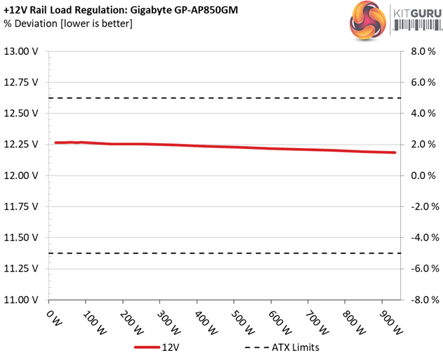
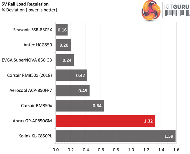
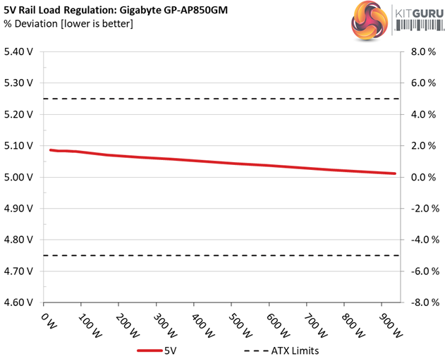
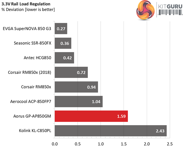
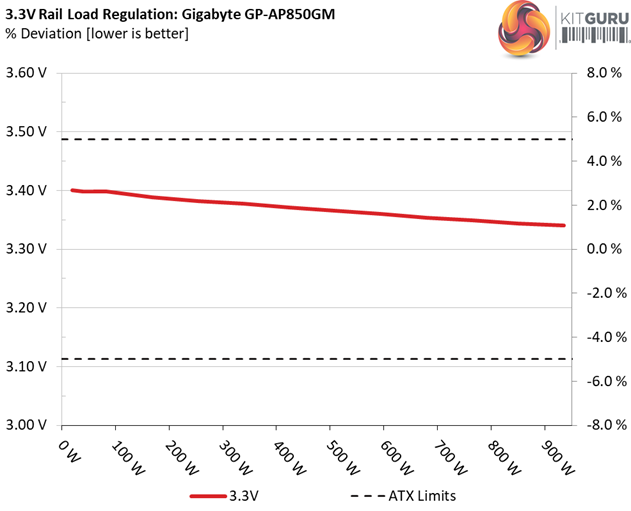
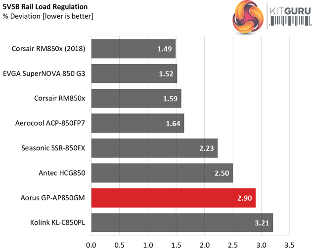
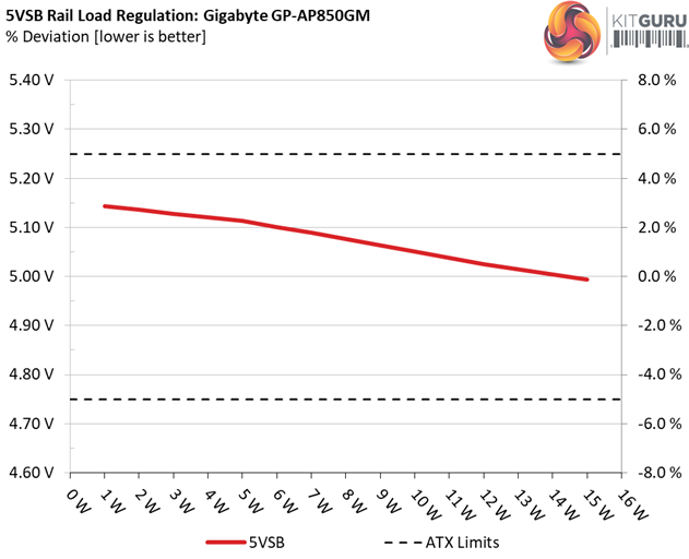
The load regulation at +12V is tight enough, while on the 5V and 3.3V rails stays within 2%. At 5VSB is at 2.9% so it could use some more tuning, although load regulation on this rail isn't of great importance. In the efficiency section, the PSU easily meets the 80 PLUS Gold requirements, although we test at a much higher ambient than the 80 PLUS organisation, where efficiency takes a big hit.
The fan profile is not aggressive, but not super relaxed either. The output noise breaks the 40 dB(A) mark during test #8 and in the overload test the fan makes its presence well felt at 46.5 dB(A). Finally, the semi-passive mode is only active during the two light load tests (test #1 and CL1).
Efficiency
Our efficiency testing procedure is detailed here.
Using results from the previous page, we plotted a chart showing the GP-AP850GM’s efficiency at low loads, and loads from 10 to 110 percent of its maximum-rated capacity.

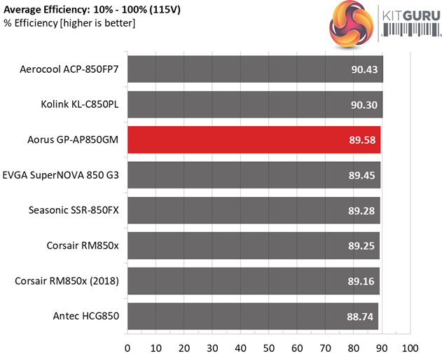
The Aorus unit naturally takes the lead from the Gold competition, however it stays behind two Platinum models with similar capacity. With light loads its efficiency is not high.
Efficiency At Low Loads
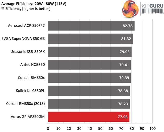
In the following tests, we measure the GP-AP850GM's efficiency at loads significantly lower than 10 percent of its maximum capacity (the lowest load the 80 PLUS standard measures). The loads we dial are 20, 40, 60, and 80W. This is important for representing when a PC is idle, with power-saving features turned on.
| Test # | 12V | 5V | 3.3V | 5VSB | DC/AC (Watts) | Efficiency | Fan Speed (RPM) | PSU Noise (dB[A]) | PF/AC Volts |
| 1 | 1.172A | 0.492A | 0.469A | 0.194A | 19.470 | 64.937% | 0 | <6.0 | 0.796 |
| 12.266V | 5.086V | 3.400V | 5.143V | 29.983 | 115.11V | ||||
| 2 | 2.414A | 0.984A | 0.969A | 0.390A | 39.903 | 78.102% | 0 | <6.0 | 0.905 |
| 12.264V | 5.084V | 3.398V | 5.136V | 51.091 | 115.11V | ||||
| 3 | 3.593A | 1.477A | 1.440A | 5.128A | 59.481 | 83.344% | 0 | <6.0 | 0.948 |
| 12.268V | 5.084V | 3.398V | 5.128V | 71.368 | 115.12V | ||||
| 4 | 4.833A | 1.968A | 1.942A | 0.781A | 79.883 | 85.471% | 0 | <6.0 | 0.960 |
| 12.266V | 5.083V | 3.398V | 5.120V | 93.462 | 115.12V |
The fan is not engaged at all under light loads, keeping the unit's output noise at minimal levels. We are not left satisfied by the registered efficiency levels though. We would like to see close to 70% with 20W load and above 80% with 40W.
5VSB Efficiency
The ATX specification (revision 1.4), along with CEC, ErP Lot 3 2014 and ErP Lot 6 2010/2013, states that the 5VSB standby supply efficiency should be as high as possible, recommending 75 percent or higher with 550mA, 1A, and 1.5A of load.
The supply should also achieve higher than 75% efficiency at 5VSB under full load, or with 3A if its max current output on this rail is higher than 3A.
We take six measurements: one each at 100, 250, 550, 1000, and 1500mA, and one with the full load the 5VSB rail can handle.
| Test # | 5VSB | DC/AC (Watts) |
Efficiency | PF/AC Volts |
| 1 | 0.100A | 0.515 | 78.626% | 0.062 |
| 5.148V | 0.655 | 115.10V | ||
| 2 | 0.250A | 1.286 | 79.678% | 0.143 |
| 5.144V | 1.614 | 115.10V | ||
| 3 | 0.550A | 2.824 | 79.842% | 0.250 |
| 5.135V | 3.537 | 115.10V | ||
| 4 | 1.000A | 5.122 | 80.156% | 0.331 |
| 5.122V | 6.390 | 115.10V | ||
| 5 | 1.500A | 7.661 | 79.282% | 0.377 |
| 5.107V | 9.663 | 115.10V | ||
| 6 | 3.000A | 15.190 | 78.118% | 0.437 |
| 5.063V | 19.445 | 115.10V |
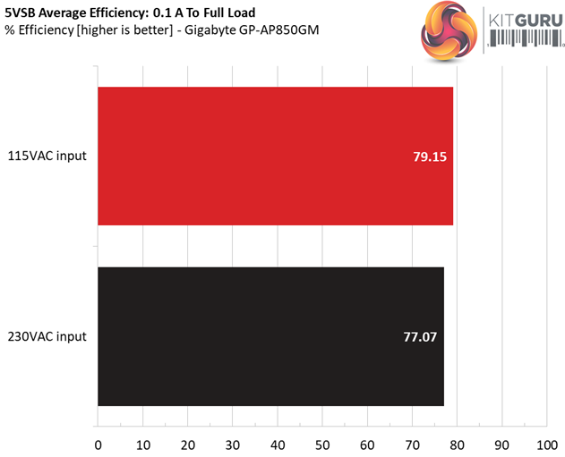
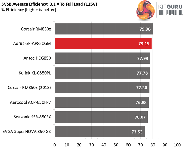
The 5VSB rail is highly efficient and stacks up pretty well against similar capacity units.
Power Consumption In Idle And Standby
In the table below, you’ll find the power consumption and voltage values of all rails (except -12V) when the PSU is idle (powered on, but without any load on its rails), and the power consumption when the unit is in standby mode (without any load, at 5VSB).
| Mode | 12V | 5V | 3.3V | 5VSB | Watts | PF/AC Volts |
| Idle | 12.250V | 5.079V | 3.388V | 5.149V | 7.823 | 0.414 |
| 115.1V | ||||||
| Standby | 0.024 | 0.002 | ||||
| 115.1V | ||||||
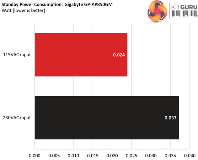
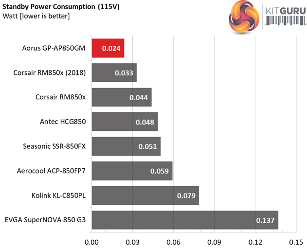
The vampire power levels of this platform are really low. Cudos to MEIC for this.
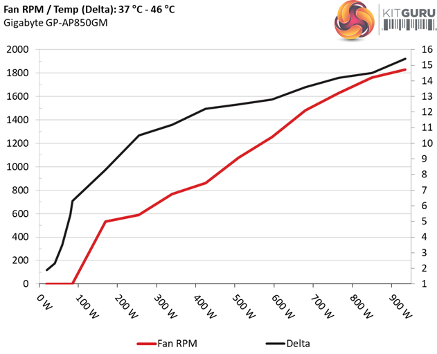
Fan RPM, Delta Temperature, And Output Noise
Our mixed noise testing is described in detail here.
The first chart below illustrates the cooling fan's speed (in RPM), and the delta between input and output temperature. The results were obtained at 37°C (98.6°F) to 46°C (114.8°F) ambient temperature.
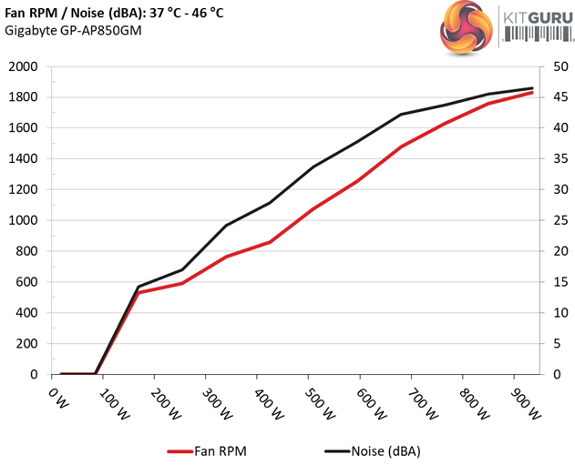
The next chart shows the cooling fan's speed (again, in RPM) and output noise. We measure acoustics from one meter away, inside a hemi-anechoic chamber. Background noise inside the chamber is below 6 dB(A) during testing (it's actually much lower, but our sound meter’s microphone hits its floor), and the results are obtained with the PSU operating at 37°C (98.6°F) to 46°C (114.8°F) ambient temperature.
The following graph illustrates the fan's output noise over the PSU's operating range. The same conditions of the above graph apply to our measurements, though the ambient temperature is between 30°C (86°F) to 32°C (89.6°F).
The passive operation doesn't last long, but the fan spins at very low speeds up to 300W load (at +12V). It takes more than 550W load at +12V for the fan to enter the 30-35 dB(A) noise while the 40 dB(A) mark is passed with >710W load.
Protection Features
Our protection features evaluation methodology is described in detail here.
|
Protection Features |
|
|
OCP |
12V: 88.4A (125.39%), 12.157V |
|
OPP |
1076.5W (126.65%) |
|
OTP |
✓ (185°C @ 12V Heat Sink) |
|
SCP |
12V: ✓ |
|
PWR_OK |
Proper Operation |
|
NLO |
✓ |
|
SIP |
Surge: MOV |
The over current triggering point at +12V is at a good level, and the same goes for the corresponding setting of the over power protection feature, which doesn't allow the PSU to deliver more than 130% of its nominal power output.
Typically OCP is set quite high on the minor rails (5V and 3.3V), while it is reasonably set at 5VSB. The good thing here is that none of the rails exceeds the ATX ripple and load regulation limits under worst case scenario. A properly configured protection feature must never allow this to happen.
There is over temperature protection and as we expected it is set high, since this unit features a semi-passive operation. Finally, there is short circuit protection on all rails and the power ok signal is accurate.
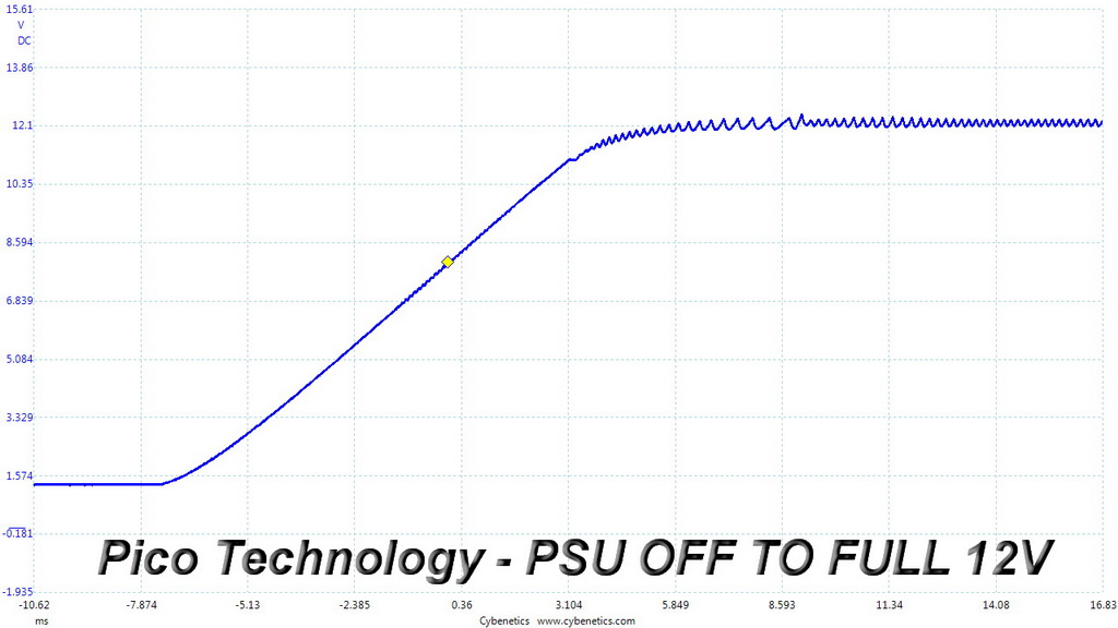
DC Power Sequencing
According to Intel’s most recent Power Supply Design Guide (revision 1.4) the +12V and 5V voltages must be equal or greater than the 3.3V rail’s output at all times, during the power-up and normal operation. For our first measurement, we turn the unit off and switch it back on without any load in any of the rails.
In the second test, we set the PSU to standby mode, dial full load and start it afterwards. In the last test, while the power supply is completely switched off (we cut off the power or switch the supply off through its power switch), we dial full load before restoring power.
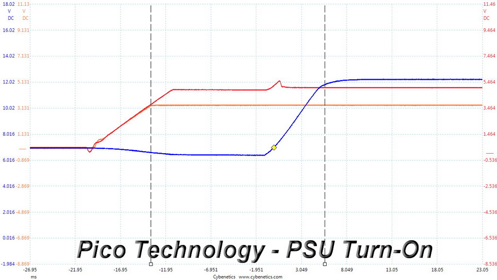

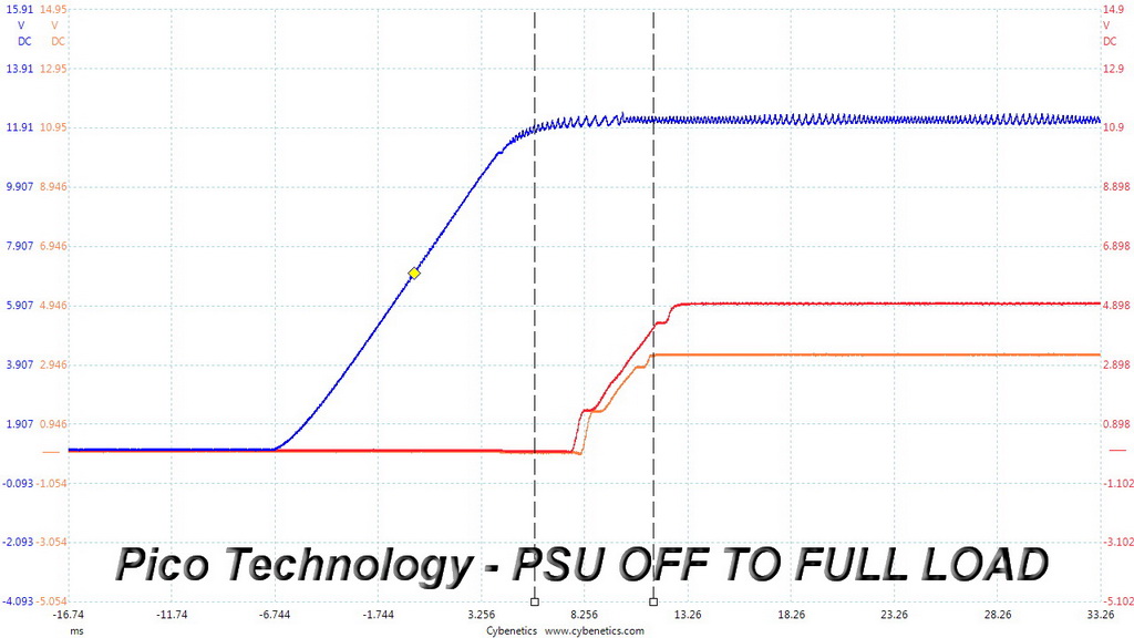
It looks like that we have a problem here, since the +12V rail starts late as you can clearly see in the first two scope shots. This means that the 3.3V rail is at a higher level than 12V, during the PSU's start up and there is also a cross correlation between the 3.3V and 5V rails. MEIC has to fix this platform's power sequencing according to Intel's specifications. Strangely enough during the last test “PSU Off to Full Load” the +12V rail starts to rise before 3.3V.
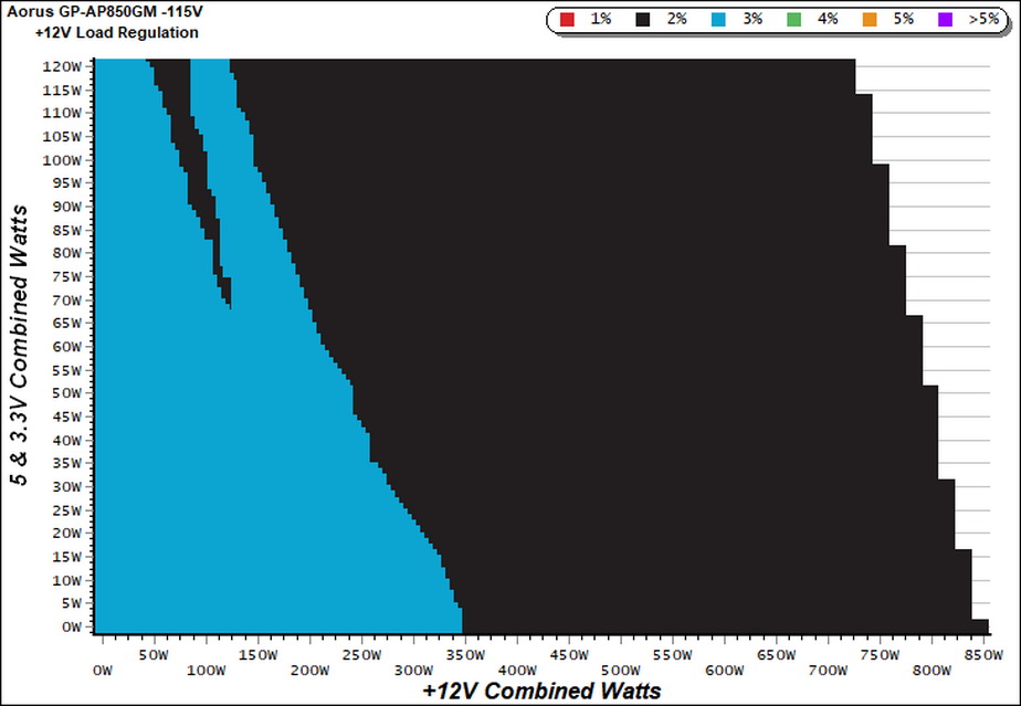
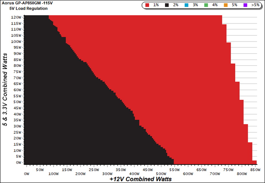
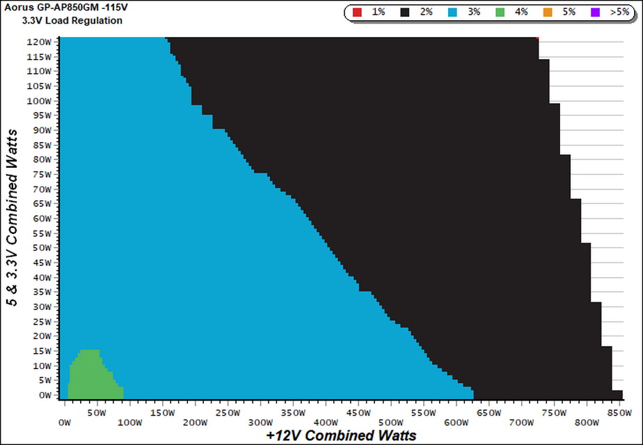
Our cross-load tests are described in detail here.
To generate the following charts, we set our loaders to auto mode through our custom-made software before trying more than 1500 possible load combinations with the +12V, 5V, and 3.3V rails. The load regulation deviations in each of the charts below are calculated by taking the nominal values of the rails (12V, 5V, and 3.3V) as point zero. The ambient temperature is between at 30°C (86°F) to 32°C (89.6°F).
Load Regulation Charts
Efficiency Chart
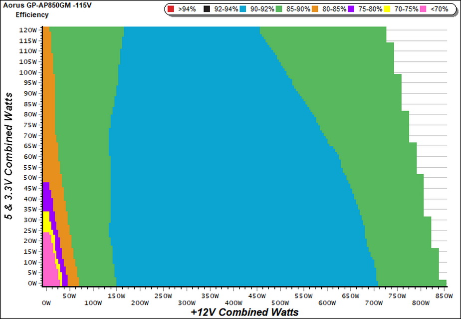
We would like to see a region with over 92% efficiency, since this unit is 80 PLUS Gold certified.
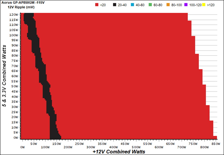
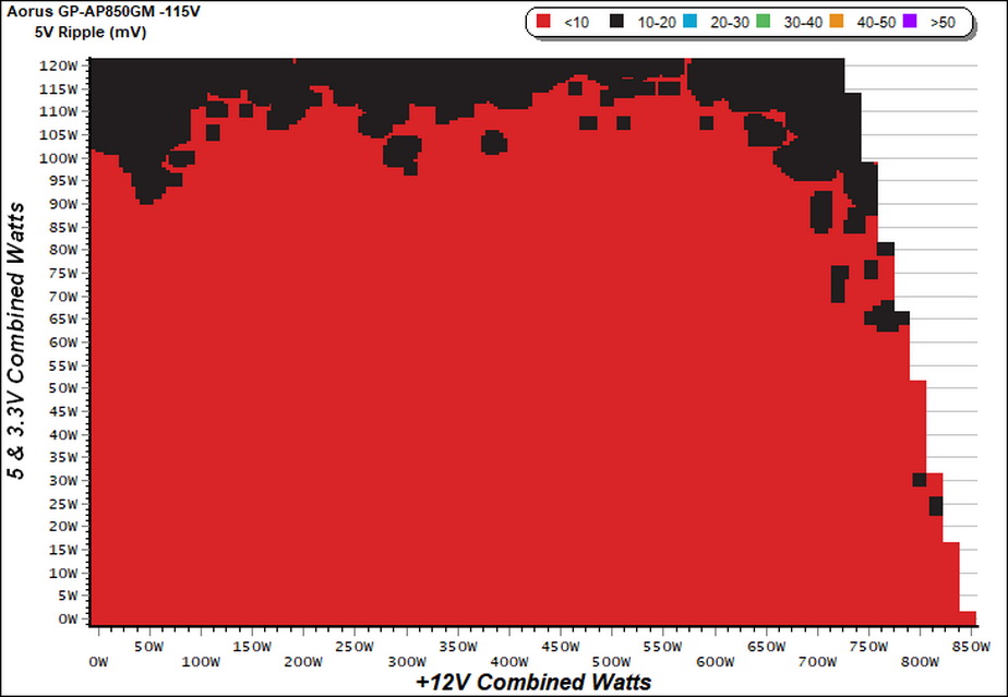
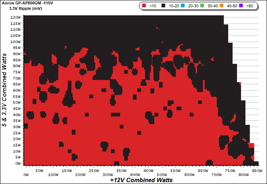
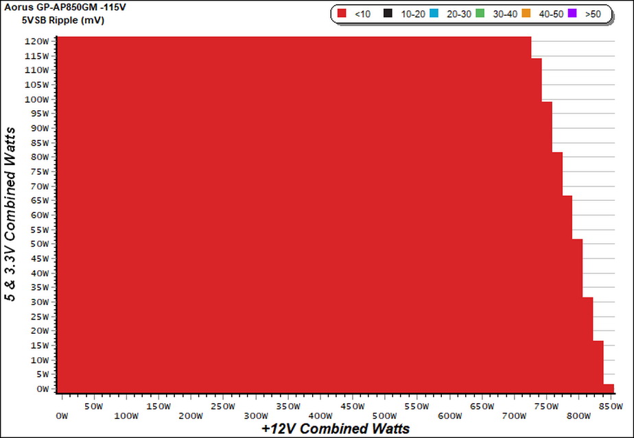
Ripple Charts
Infrared Images
We apply half-load for 10 minutes with the PSU’s top cover and cooling fan removed before taking photos with our modified FLIR E4 camera that delivers 320×240 IR resolution (76,800 pixels).
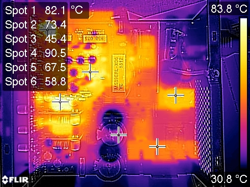
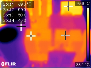
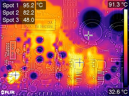
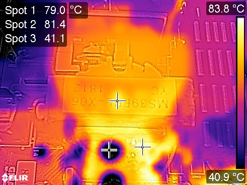
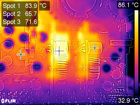
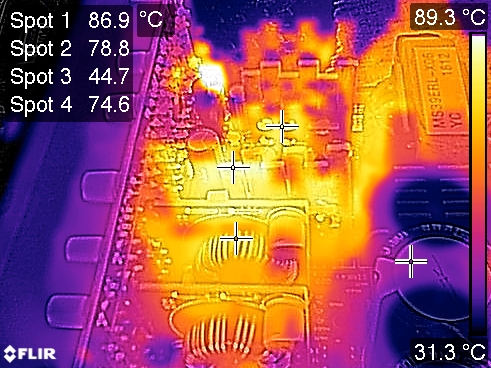
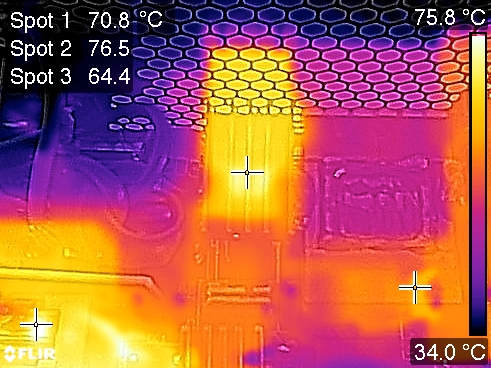
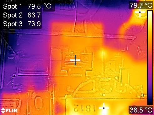
Our IR camera revealed that the DC-DC converters can get quite hot, however we applied close to 10 Amps load in each of them during those tests, which is quite high and under normal conditions they won't have to handle such high loads. But we always have to take the extreme and toughest usage scenarios in order to be sure about our results and findings.
Advanced Transient Response Tests
For details on our transient response testing, please click here.
These tests are crucial because they simulate the transient loads a PSU is likely to handle (such as booting a RAID array or an instant 100 percent load of CPU/GPUs). We call these “Advanced Transient Response Tests” and they are designed to be very tough to master, especially for a PSU with a capacity of less than 500W.
In all of the tests, we use an oscilloscope to measure the voltage drops caused by the transient load. The voltages should remain within the ATX specification's regulation limits.
We should note here that the ATX spec requires for capacitive loading during the transient rests, but in our methodology we chose to apply the worst case scenario with no extra capacitance on the rails.
Advanced Transient Response at 20 Percent – 200ms
| Voltage | Before | After | Change | Pass/Fail |
|---|---|---|---|---|
| 12V | 12.255V | 12.174V | 0.66% | Pass |
| 5V | 5.074V | 5.019V | 1.08% | Pass |
| 3.3V | 3.390V | 3.317V | 2.15% | Pass |
| 5VSB | 5.100V | 5.065V | 0.69% | Pass |
Advanced Transient Response at 20 Percent – 20ms
| Voltage | Before | After | Change | Pass/Fail |
|---|---|---|---|---|
| 12V | 12.253V | 12.122V | 1.07% | Pass |
| 5V | 5.073V | 5.015V | 1.14% | Pass |
| 3.3V | 3.390V | 3.296V | 2.77% | Pass |
| 5VSB | 5.100V | 5.063V | 0.73% | Pass |
Advanced Transient Response at 20 Percent – 1ms
| Voltage | Before | After | Change | Pass/Fail |
|---|---|---|---|---|
| 12V | 12.252V | 12.143V | 0.89% | Pass |
| 5V | 5.072V | 5.007V | 1.28% | Pass |
| 3.3V | 3.388V | 3.304V | 2.48% | Pass |
| 5VSB | 5.100V | 5.062V | 0.75% | Pass |
Advanced Transient Response at 50 Percent – 200ms
| Voltage | Before | After | Change | Pass/Fail |
|---|---|---|---|---|
| 12V | 12.234V | 12.175V | 0.48% | Pass |
| 5V | 5.053V | 5.001V | 1.03% | Pass |
| 3.3V | 3.374V | 3.302V | 2.13% | Pass |
| 5VSB | 5.063V | 5.027V | 0.71% | Pass |
Advanced Transient Response at 50 Percent – 20ms
| Voltage | Before | After | Change | Pass/Fail |
|---|---|---|---|---|
| 12V | 12.234V | 12.150V | 0.69% | Pass |
| 5V | 5.052V | 4.985V | 1.33% | Pass |
| 3.3V | 3.372V | 3.281V | 2.70% | Pass |
| 5VSB | 5.063V | 5.013V | 0.99% | Pass |
Advanced Transient Response at 50 Percent – 1ms
| Voltage | Before | After | Change | Pass/Fail |
|---|---|---|---|---|
| 12V | 12.232V | 12.144V | 0.72% | Pass |
| 5V | 5.051V | 4.998V | 1.05% | Pass |
| 3.3V | 3.372V | 3.285V | 2.58% | Pass |
| 5VSB | 5.063V | 5.024V | 0.77% | Pass |
The Aorus unit offers very good transient response on all rails. MEIC delivered a highly capable platform to Gigabyte, given the results so far.
Here are the oscilloscope screenshots we took during Advanced Transient Response Testing:
Transient Response At 20 Percent Load – 200ms

Transient Response At 20 Percent Load – 20ms
Transient Response At 20 Percent Load – 1ms

Transient Response At 50 Percent Load – 200ms
Transient Response At 50 Percent Load – 20ms
Transient Response At 50 Percent Load – 1ms


Turn-On Transient Tests
In the next set of tests, we measure the GP-AP850GM’s response in simpler transient load scenarios—during its power-on phase.
For our first measurement, we turn the GP-AP850GM off, dial in the maximum current the 5VSB rail can handle, and switch the PSU back on.
In the second test, we dial the maximum load the +12V rail can handle and start the PSU while it is in standby mode. In the last test, while the PSU is completely switched off (we cut off the power or switch the PSU off through its power switch), we dial the maximum load the +12V rail can handle before restoring power. The ATX specification states that recorded spikes on all rails should not exceed 10 percent of their nominal values (+10 percent for 12V is 13.2V, and 5.5 V for 5V).
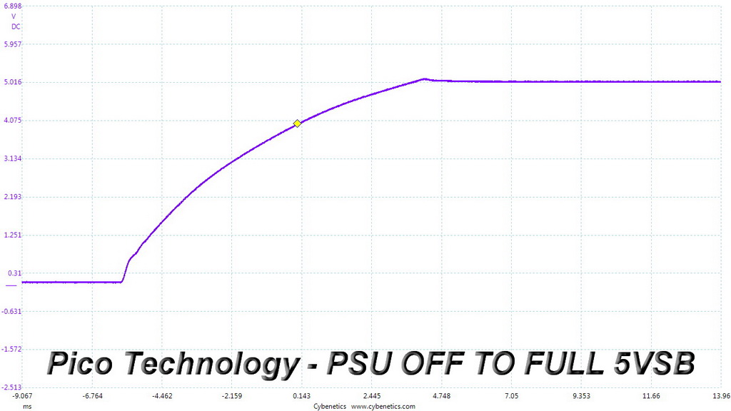
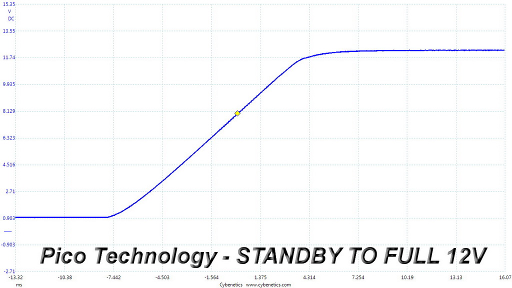
Almost perfect results here, A small period with increased ripple during the last test spoiled a bit the overall great picture, however this is nothing to worry about since there are no spikes or notable overshoots at +12V.
To learn how we measure ripple, please click here.
The following table includes the ripple levels we measured on the GP-AP850GM’s rails. The limits, according to the ATX specification, are 120mV (+12V) and 50mV (5V, 3.3V, and 5VSB).
| Test | 12V | 5V | 3.3V | 5VSB | Pass/Fail |
| 10% Load | 4.9 mV | 6.2 mV | 13.1 mV | 5.2 mV | Pass |
| 20% Load | 22.5 mV | 7.2 mV | 13.2 mV | 6.4 mV | Pass |
| 30% Load | 7.1 mV | 6.1 mV | 12.3 mV | 4.9 mV | Pass |
| 40% Load | 5.6 mV | 6.5 mV | 11.9 mV | 4.9 mV | Pass |
| 50% Load | 5.6 mV | 7.3 mV | 12.3 mV | 4.7 mV | Pass |
| 60% Load | 6.4 mV | 8.9 mV | 13.6 mV | 6.5 mV | Pass |
| 70% Load | 7.0 mV | 10.1 mV | 14.5 mV | 6.7 mV | Pass |
| 80% Load | 8.3 mV | 10.3 mV | 14.2 mV | 7.7 mV | Pass |
| 90% Load | 7.7 mV | 9.1 mV | 15.2 mV | 6.4 mV | Pass |
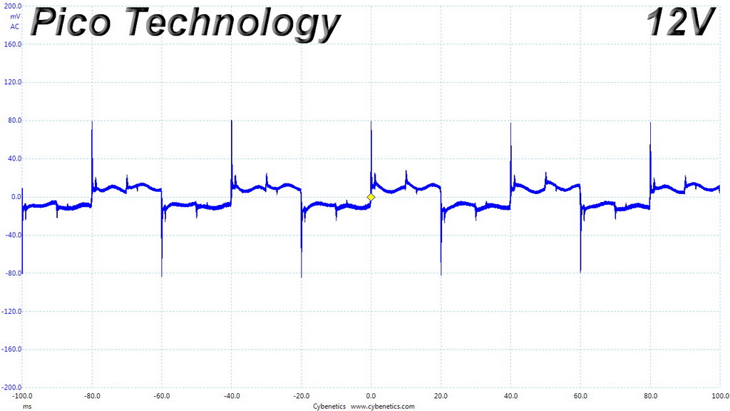
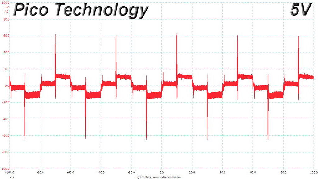
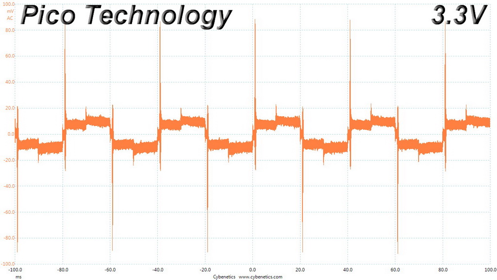
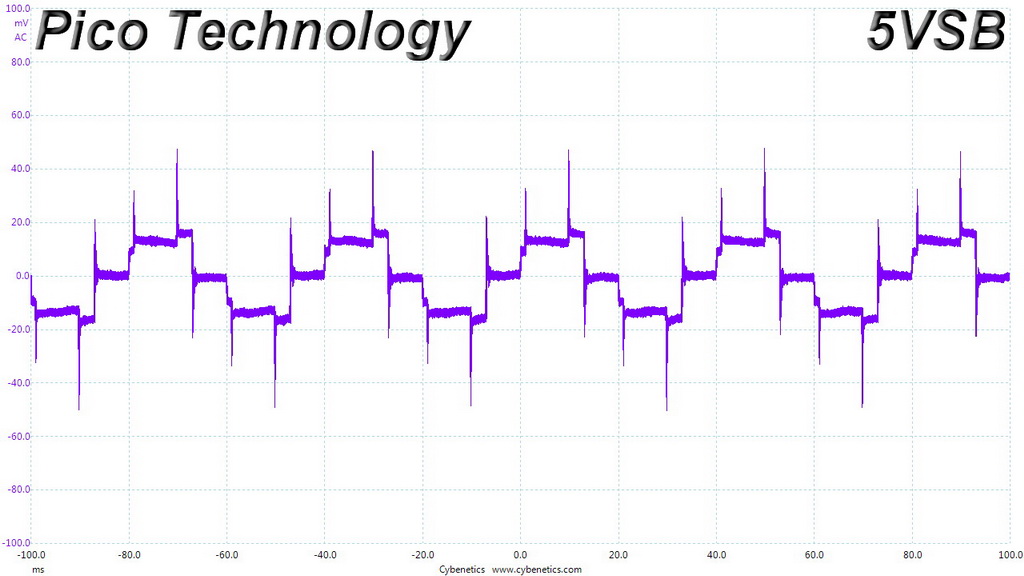
| 100% Load | 11.3 mV | 14.4 mV | 18.2 mV | 10.3 mV | Pass |
| 110% Load | 77.1 mV | 28.6 mV | 52.9 mV | 26.6 mV | Fail |
| Crossload 1 | 27.1 mV | 16.9 mV | 19.3 mV | 5.8 mV | Pass |
| Crossload 2 | 9.9 mV | 11.5 mV | 16.1 mV | 7.8 mV | Pass |
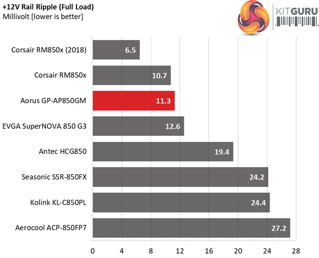
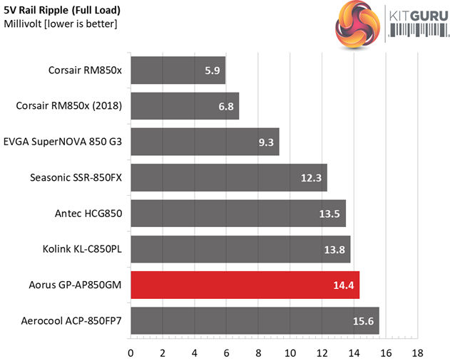
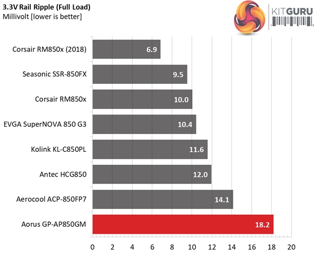
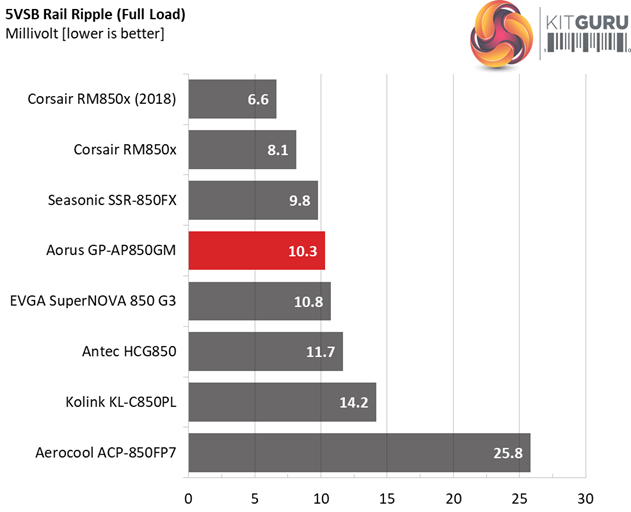
The ripple suppression is great on all rails, as long as you don't exceed the platform's nominal capacity (which normally you should not do in any case). Apparently this platform doesn't provide much of a headroom, so even with 110% of the max-rated-load it starts to behave strange.
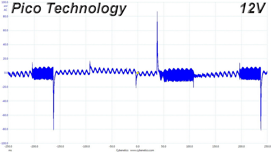
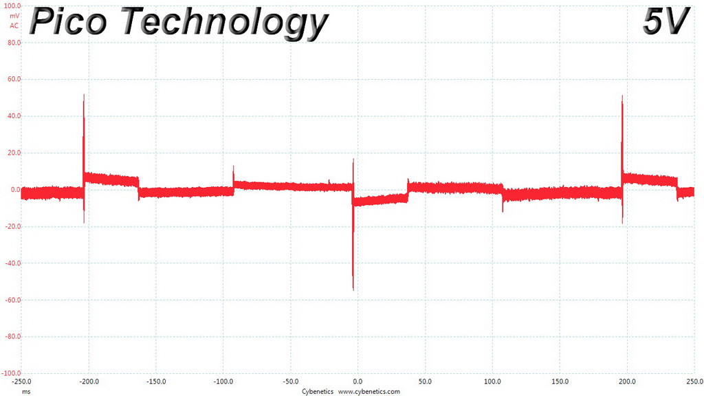
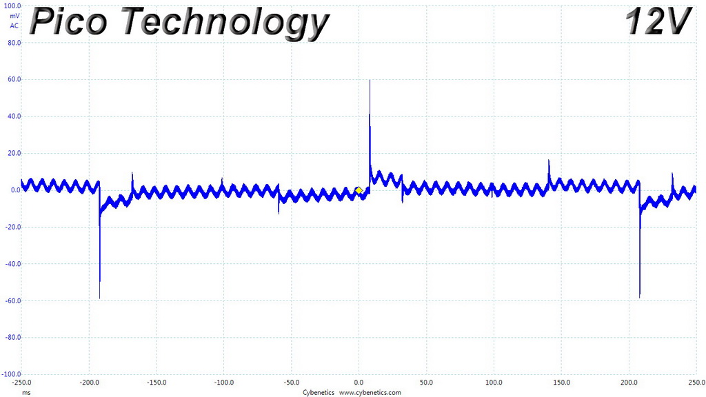
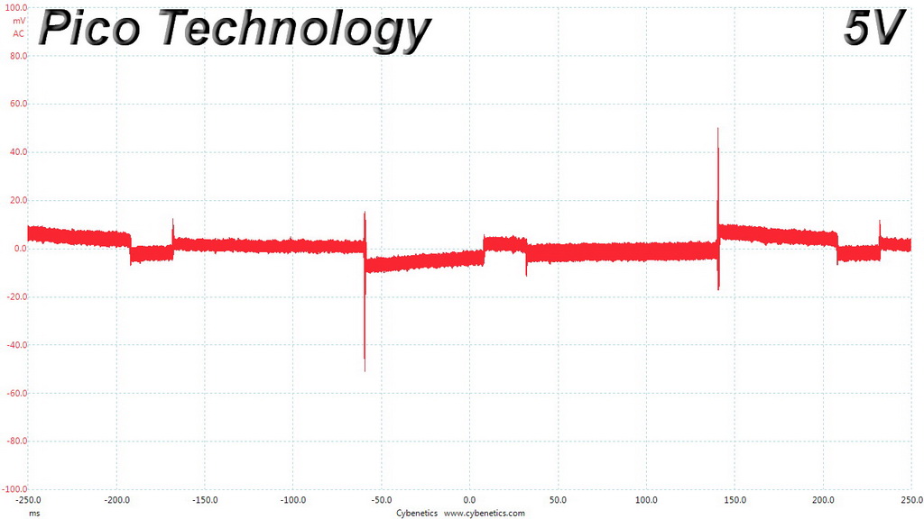
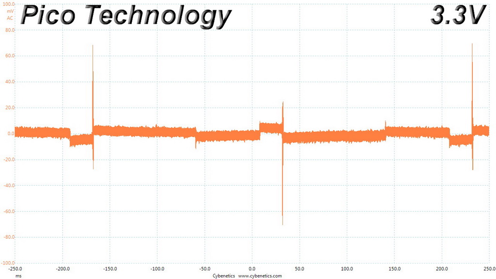
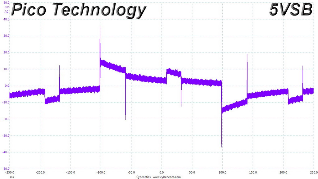
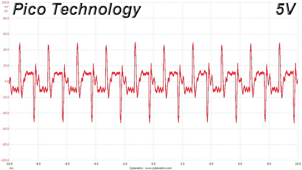
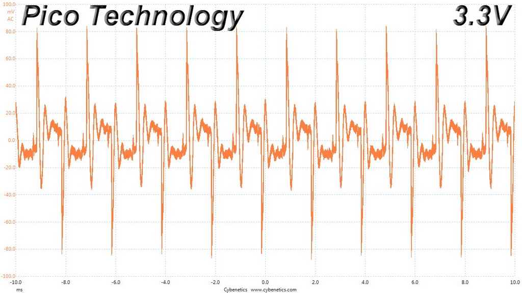
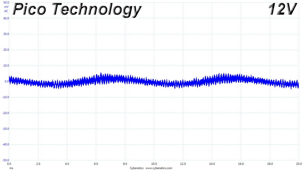
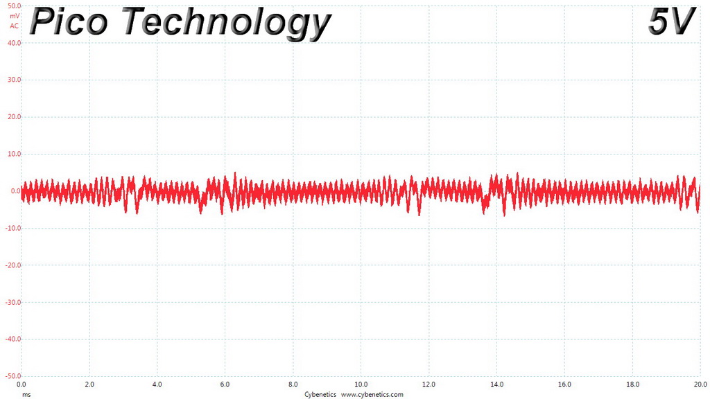
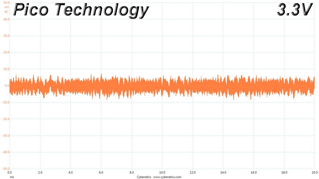
Ripple Oscilloscope Screenshots
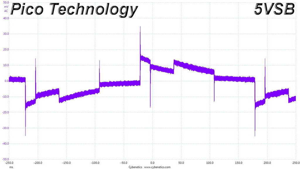
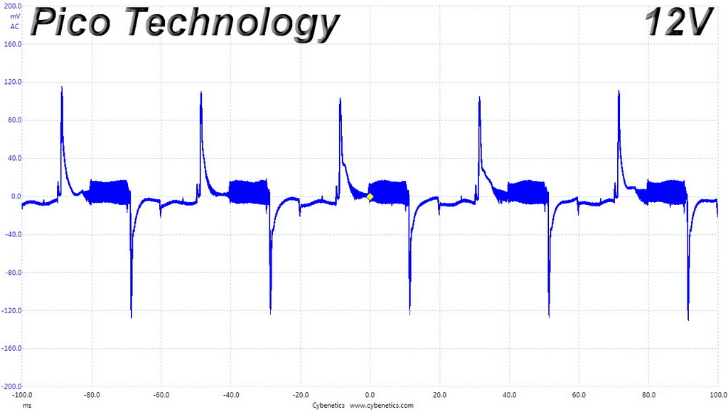
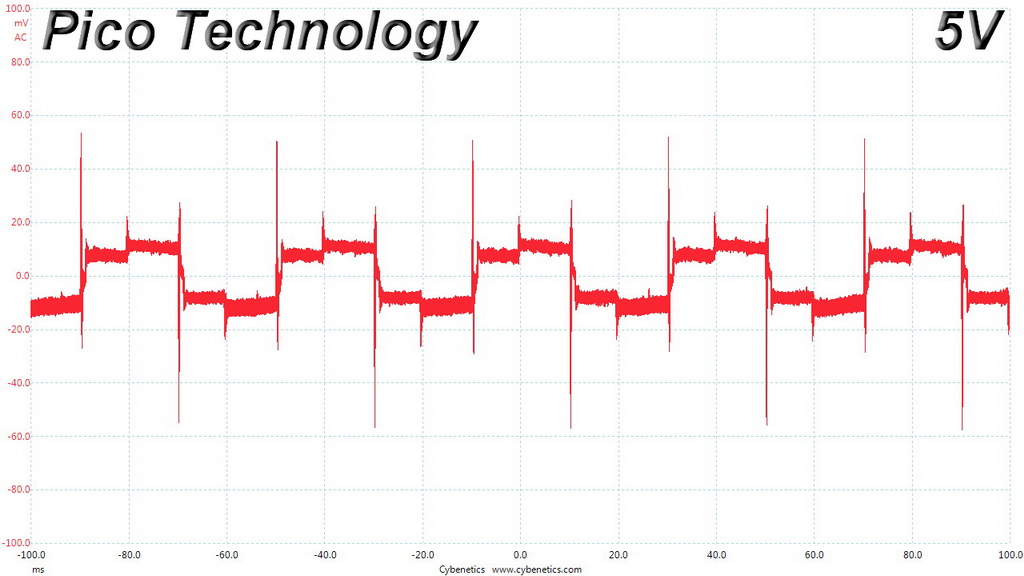
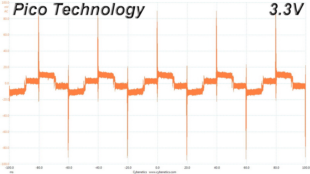
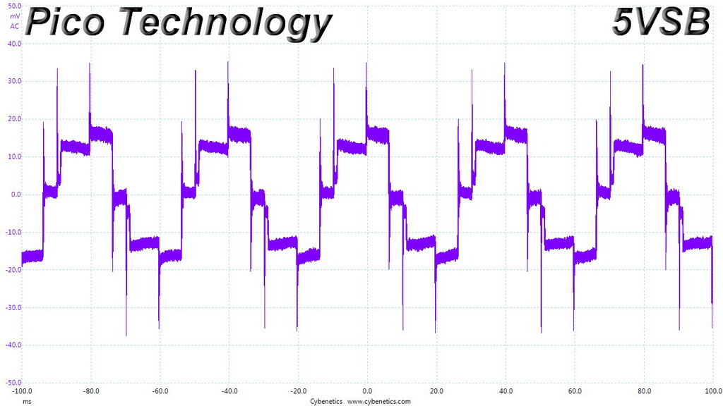
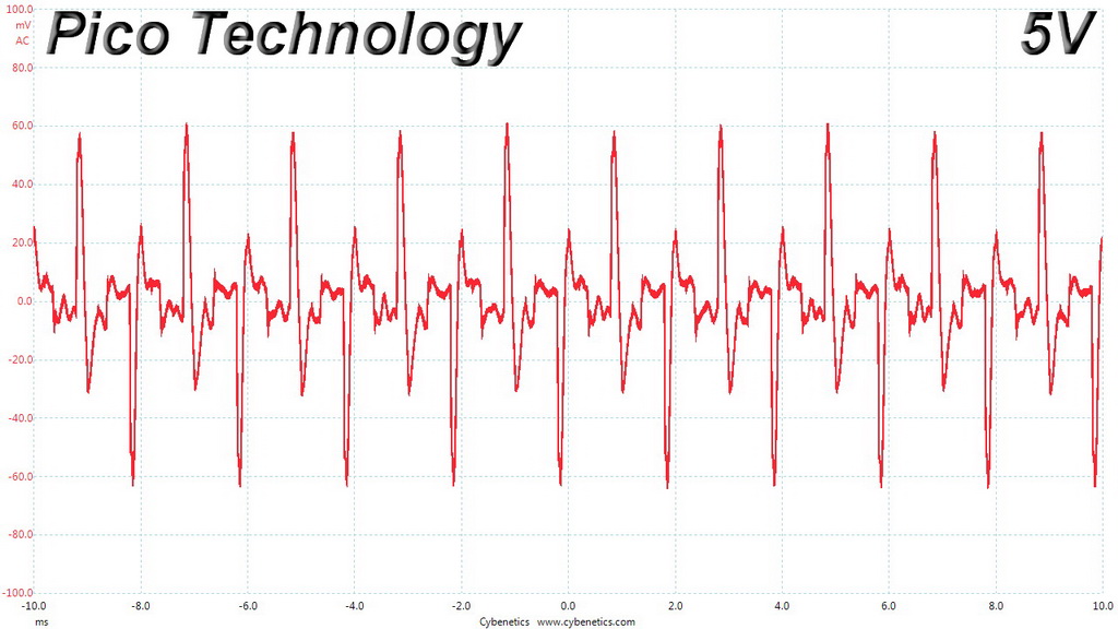
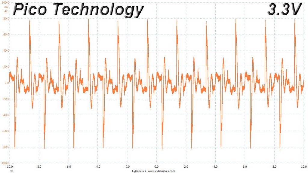
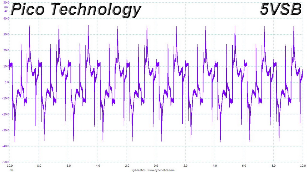
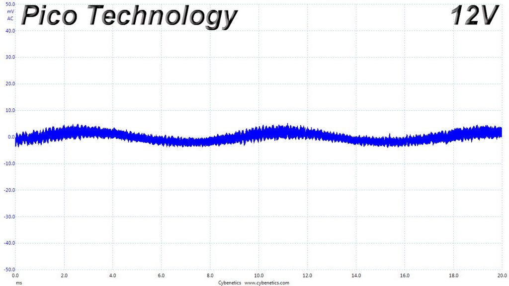
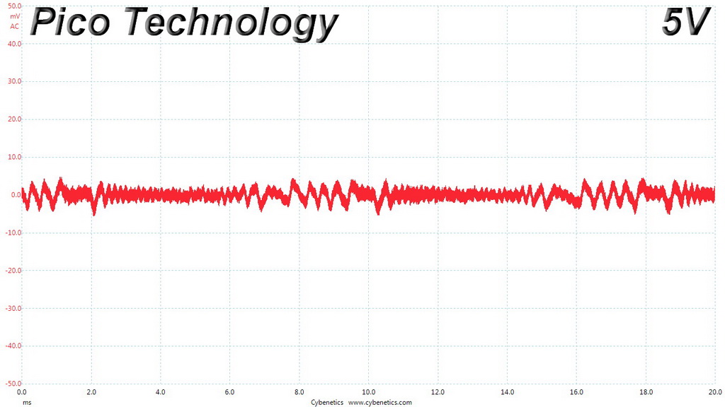
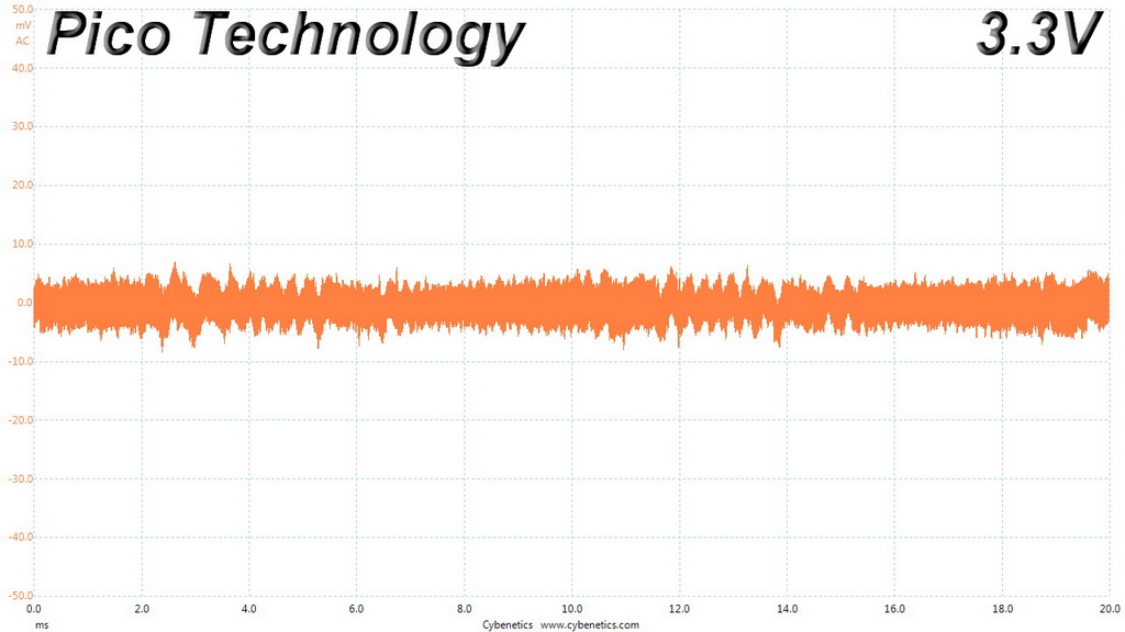
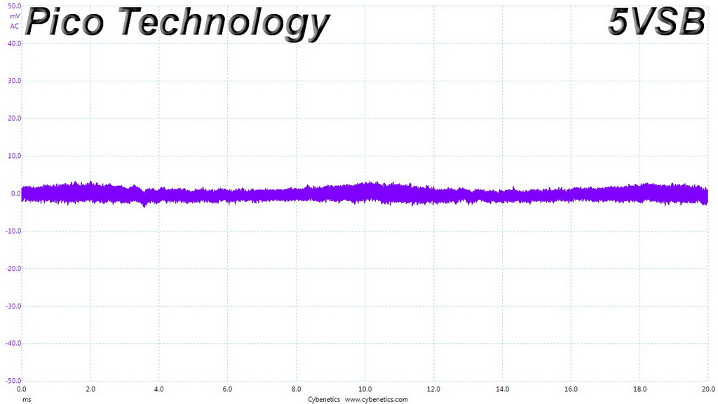
The following oscilloscope screenshots illustrate the AC ripple and noise registered on the main rails (+12V, 5V, 3.3V and 5VSB). The bigger the fluctuations on the screen, the bigger the ripple/noise. We set 0.01 V/Div (each vertical division/box equals 0.01V) as the standard for all measurements.
Ripple At Full Load
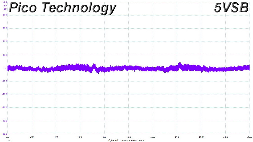
Ripple At 110-Percent Load
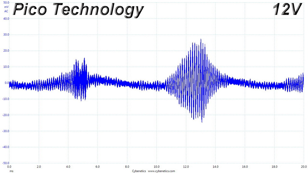
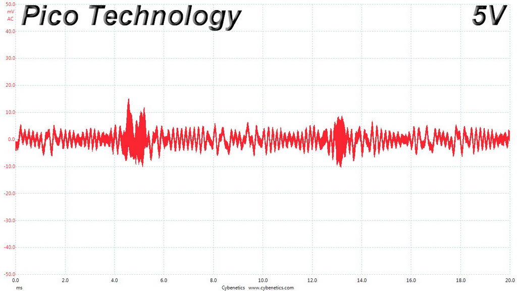
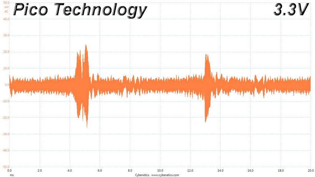
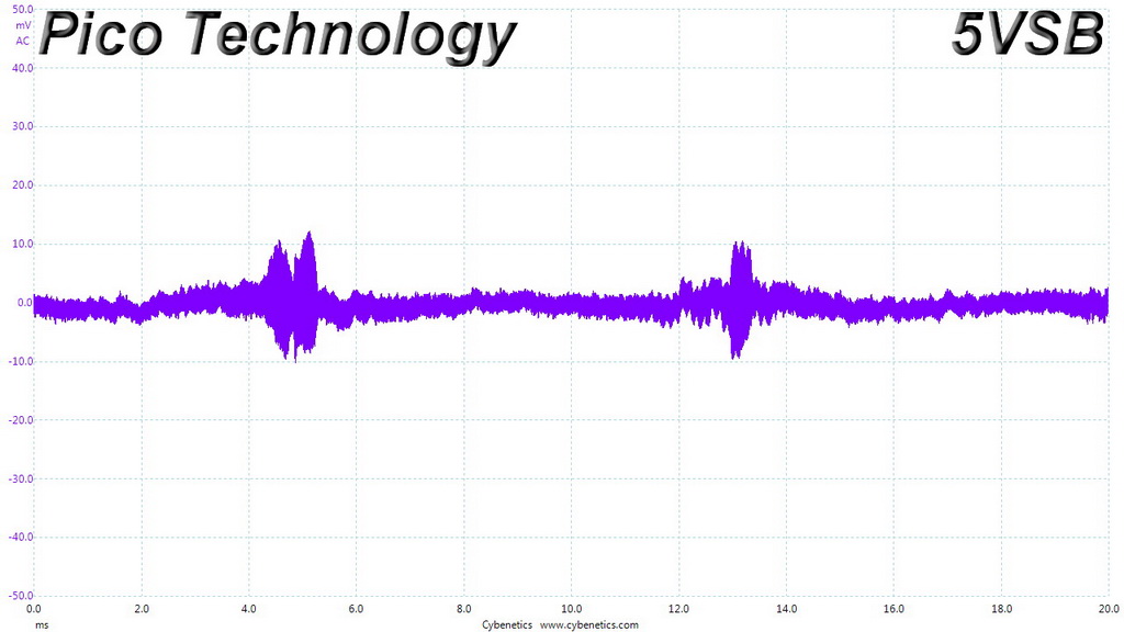
Ripple At Cross-Load 1
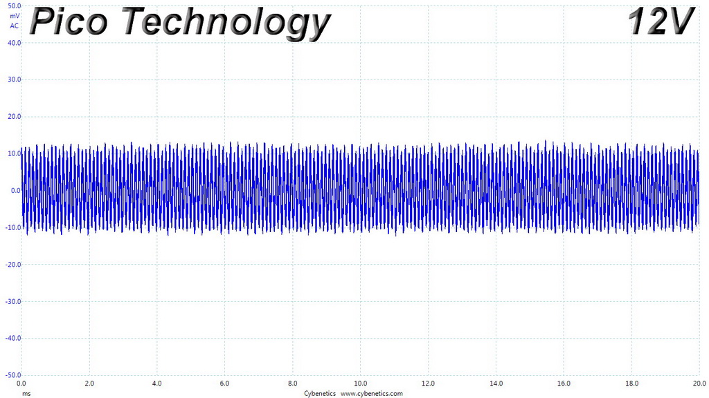
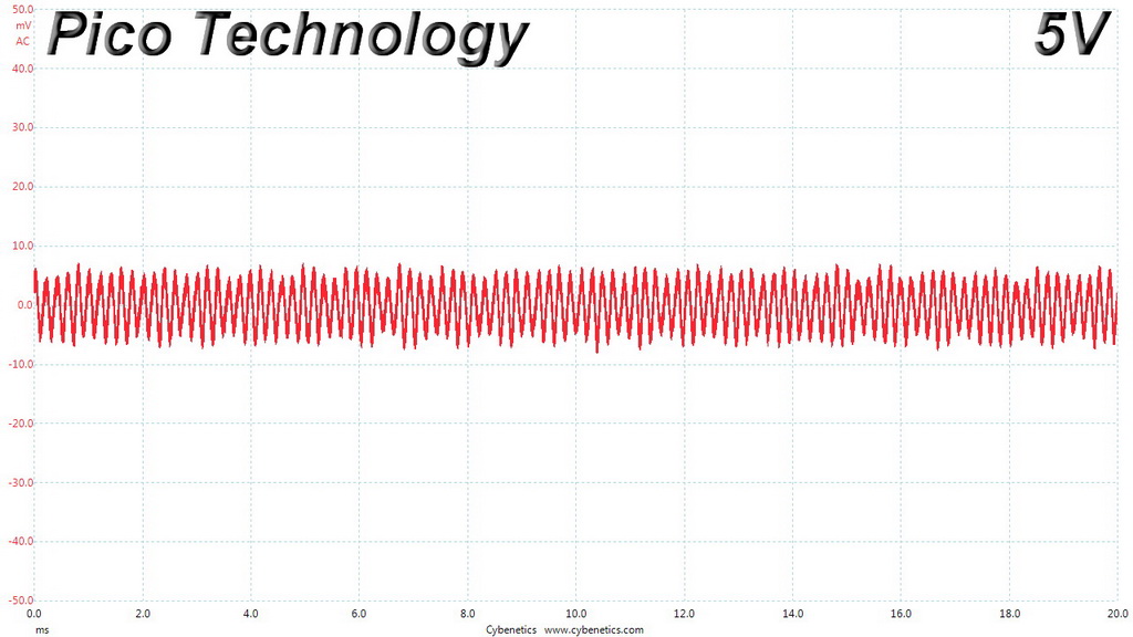
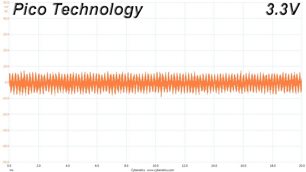
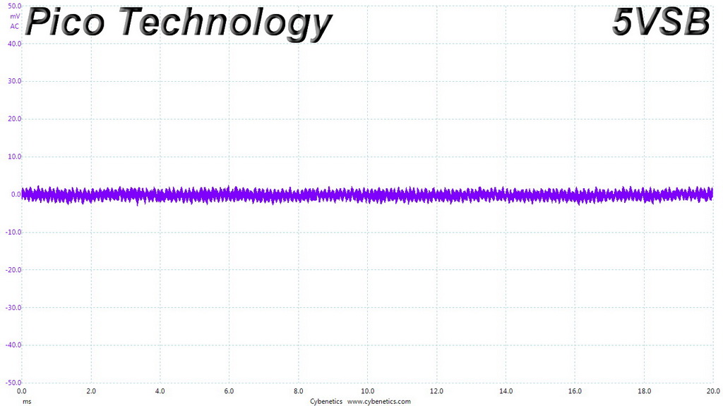
Ripple At Cross-Load 2
To learn more about our EMI testing equipment, please check out How We Test Power Supply Units.
EMI Results – Average Detector
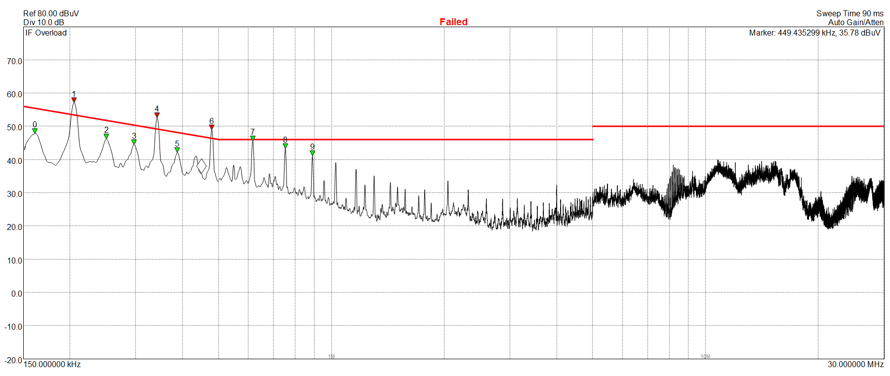
The conducted EMI with the average detector has some high spurs, three of which go over the limits. This is a shame because at higher frequencies the EMI filter does a pretty good job.
EMI Results – Peak Detector
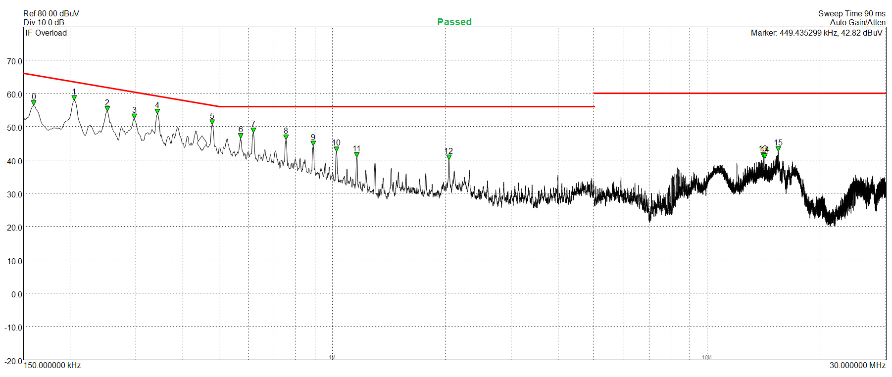
No problems at all with the peak detector.
Performance Rating
The following graph shows the GP-AP850GM’s total performance rating, comparing it to other units we have tested. To be more specific, the tested unit is shown as 100 percent, and every other unit's performance is shown relative to it.

This is a highly capable platform, able to meet eye-to-eye strong opponents like the RM850x, HCG850 and the HX850.
Performance Per Dollar
The following chart may be the most interesting to many of you because it depicts the product’s performance-per-dollar score. We looked up the current price of each PSU on popular online shops and used those prices and all relative performance numbers to calculate the index. Note that all of the numbers in the following graphs are normalized by the rated power of each unit.
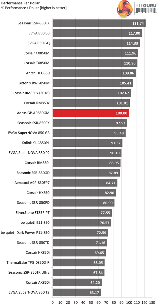
For an 80 PLUS Gold and ETA-A unit the GP-AP850GM has a fair price tag. A bit lower price though it would surely help.
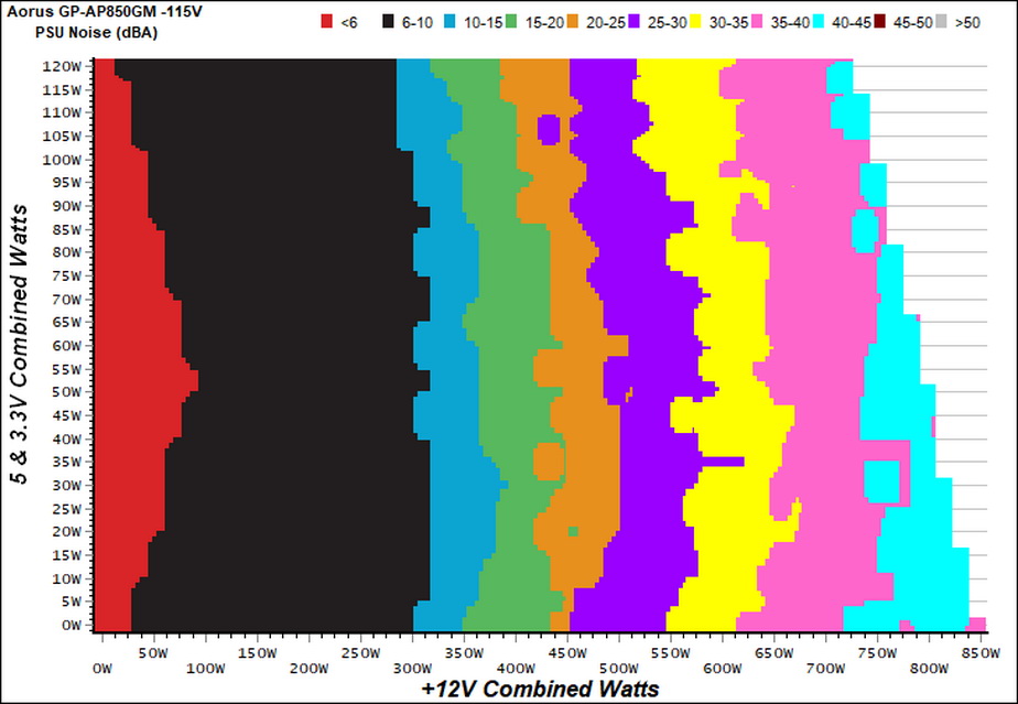
Noise Rating
The graph below depicts the cooling fan's average noise over the PSU's operating range, with an ambient temperature between 30°C and 32°C (86°F to 89.6°F).
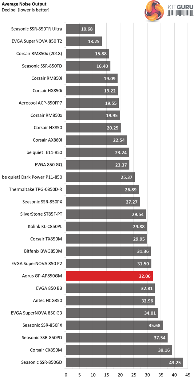
Under normal operating conditions the fan profile is not aggressive, however if you push the unit the fan will make its presence felt. This is not a noisy 850W PSU, however it is not among the most silent either.
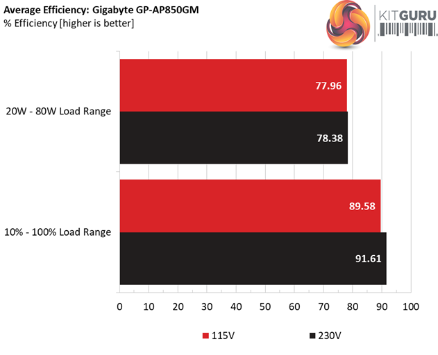
Efficiency Rating
The following graph shows the PSU's average efficiency throughout its operating range, with an ambient temperature close to 30°C.
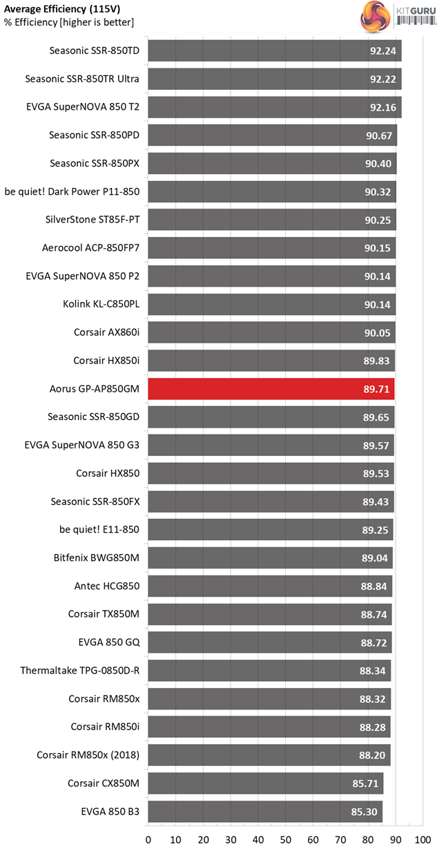
The overall efficiency is up to the expected levels, given this platform's certifications (Gold and ETA-A).
The Gigabyte Aorus GP-AP850GM retails for $149.99 in the US where it will be available mid-September. In the UK it will be sold for £124.99 and it is expected in late September.
Gigabyte had quite some time to release a new power supply line and it was a surprise that it chose to do so utilising the platform of a not so known manufacturer (MEIC). In the end this proved to be a good move though, since MEIC delivered a good product which is able to meet the performance of formidable competitors such as the Aerocool ACP-850FP7 and the Corsair HX850.
The load regulation is tight enough, the ripple suppression is excellent while the transient response is really good and this is what matters the most, since a PSU under real life conditions will constantly face transient loads.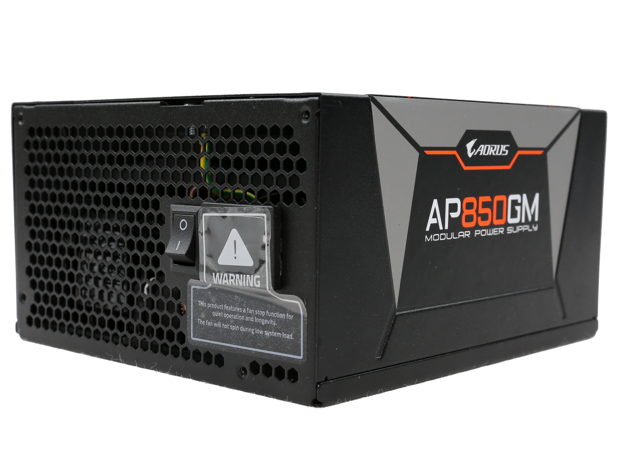
In my opinion Gigabyte should tune the fan profile to be more relaxed, since this is an efficient platform, under normal loads at least. With light loads (20-40W) a little tuning is required as well in order to increase efficiency, however I should note that the platform is able to deliver over 60% efficiency with 2% of its max-rated-capacity – something that will be a requirement in the upcoming ATX specification according to our sources (and it will be increased to 70% in the coming years).
There two EPS and six PCIe connectors in total, which are enough to fully cover the PSU's capacity. Although the 24-pin ATX, EPS and PCIe connectors are supported by in-line caps, still the corresponding cables are flexible so you won't meet any problems during the cable rooting and management processes.
Moreover, all cables are very long and the two dedicated PCIe cables are ideal for energy hungry graphics cards in order to avoid voltage drops under high loads. There are some issues though in this unit's cable configuration. For starters the six SATA connectors look few for a high-end 850W unit (the HX850 for instance comes with 16x SATA connectors). Moreover the distance between the peripheral connectors is too low at only 100mm. Finally, there is no need for the fixed FDD connector, especially from the moment a FDD adapter is provided.
Another issue that Gigabyte has to solve along with MEIC is this platform's DC power sequencing which is not inline with Intel's specs, from the moment the 3.3V rail's voltage is higher than the 12V rail's, during the PSU's start-up phase.
It is nice to see Gigabyte releasing a good product, since this will create more competition in the popular 850W category. MEIC, the manufacturer of this unit, so far didn't have a presence in the desktop PSU market since it mostly deals with power adapter. Despite the lack of experience in manufacturing desktop units, they did a fine job though and we are very interested to analyse more platforms from this OEM.
Pros:
- Resilient to high operating temperatures
- Double-ball bearing fan suitable for tough operating conditions
- High efficiency under normal loads
- Good transient response on all rails
- Very low vampire power
- Accurate power ok signal
- Fully modular with highly flexible cables
- 2x EPS and 6x PCIe connectors
- Interesting external design
- Compact dimensions
- Ten-year warranty
Cons:
- Not so high efficiency under light loads (20-40W)
- Conducted EMI with the AVG detector
- Six SATA connectors look few in a high-end 850W PSU
- Decreased distance between the peripheral connectors (only 10cm)
- No need for the fixed FDD (Berg) connector, since a FDD adapter is also provided
- The platform's DC power sequencing doesn't meet Intel's specifications
- Can be very noisy under tough conditions
- It would be nice if the semi-passive mode could be deactivated
KitGuru says: The GP-AP850GM is a highly capable PSU that manages to stand out from the crowd thanks to its nice external design and the unique platform, which isn't utilized by any other brand so far. It has good performance and under normal conditions it will remain silent. It is good to see Gigabyte/Aorus in the tough PSU market, since it increases the available options for all buyers out there.