

All that glitters is not gold! This is not the case though with the ToughPower Grand RGB since it features both Gold efficiency and RGB lighting. The unit is covered by a ten-year warranty which shows high confidence in its reliability. The big question is ‘can it compete with the Corsair RM750x and the Seasonic SSR-850FX?' – both of which don't ship any bells and whistles, but focus instead on pure performance.
Thermaltake places a huge focus on RGB lighting. This is easily seen on its power supply offerings since many of them include this feature. Personally we are not so fond of any type of lighting when it comes to power supplies since we believe that any extra penny should be spent on better parts that actually make a difference to the unit's overall performance.
In our opinion only when you have the best possible platform, you should look at those fancy extras, however we all know that fancy RGB lighting is very popular with a huge audience right now. Whether you like it or not, it seems to be here to stay.
The Toughpower Grand RGB (RGB Sync Edition) line consists of three models with capacities ranging from 650W to 850W. Thermaltake was kind enough to send us the two lower capacity models, which we will evaluate in this review – focusing more on the 750W unit which will gather the most interest, since this wattage category is among the most popular.
The TPG-750AH3FSGR (this is a really long model number!), is equipped with a 256-color Riing fan measuring 140mm in diameter. There are five lighting models and thanks to a built-in memory the unit is able to “remember” the last setting. Besides manual control, there is the option for custom RGB lighting since Thermaltake provided compatibility with popular RGB-ready mainboards including models from Asus, Gigabyte, MSI, Biostar and ASRock.
Read our How We Test Power Supplies HERE
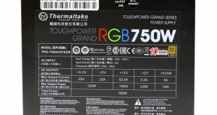
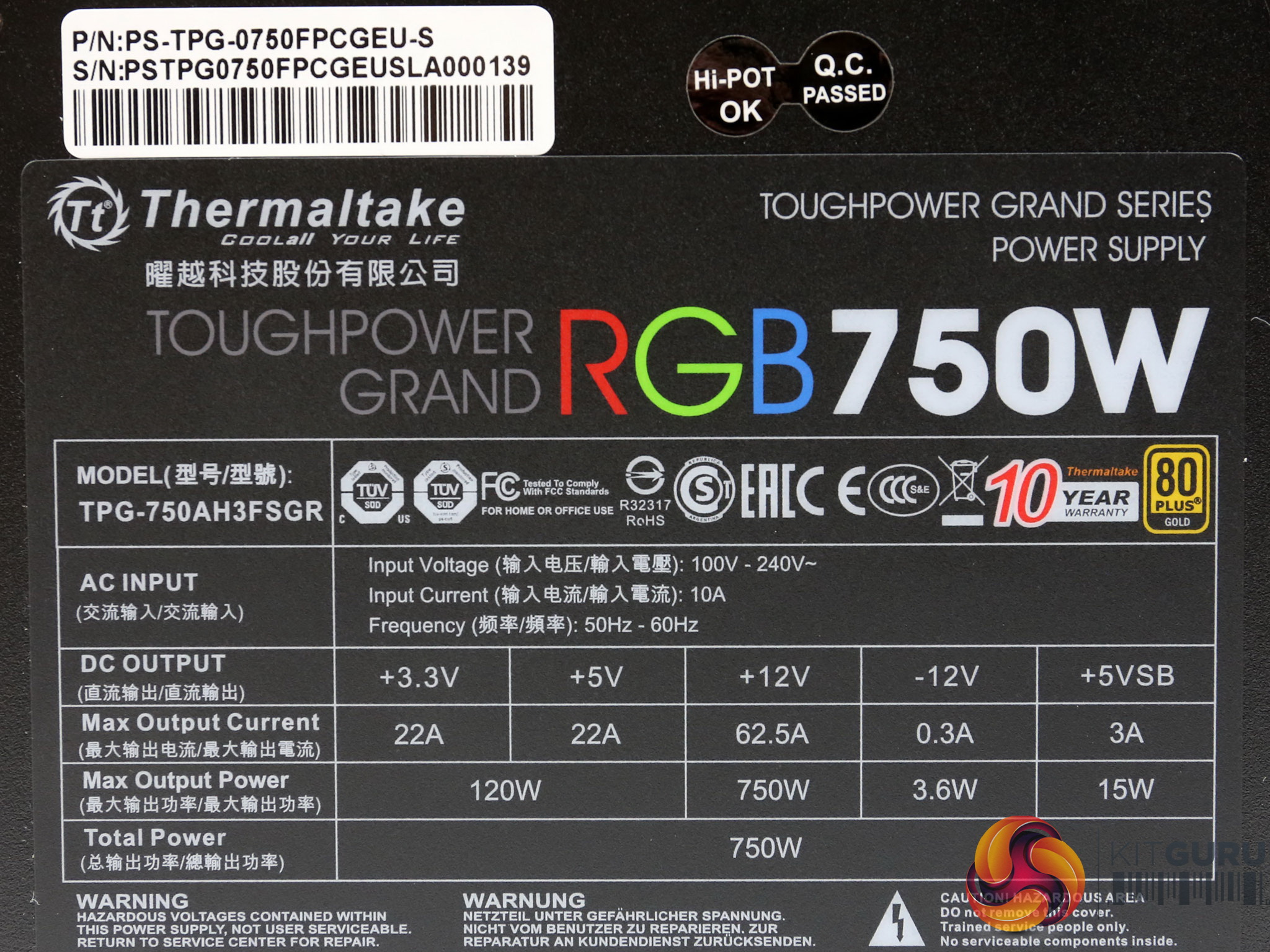
Specifications
| Manufacturer (OEM) | Sirfa / High Power |
| Max. DC Output | 750W |
| Efficiency | 80 PLUS Gold, ETA-A (88-91%) |
| Noise | LAMBDA-A- (25-30 dB[A]) |
| Modular | ✓ (Fully) |
| Intel C6/C7 Power State Support | ✓ |
| Operating Temperature | 0 – 50°C |
| Over Voltage Protection | ✓ |
| Under Voltage Protection | ✓ |
| Over Power Protection | ✓ |
| Over Current (+12V) Protection | ✓ |
| Over Temperature Protection | ✓ |
| Short Circuit Protection | ✓ |
| Surge Protection | ✓ |
| Inrush Current Protection | ✓ |
| Fan Failure Protection | ✗ |
| No Load Operation | ✓ |
| Cooling | 140mm Hydro Dynamic Bearing Fan (TT-1425 [A1425L12S]) |
| Semi-Passive Operation | ✓ (Selectable) |
| Dimensions (W x H x D) | 152 x 87 x 162mm |
| Weight | 1.63 kg (3.59 lb) |
| Form Factor | ATX12V v2.4, EPS 2.92 |
| Warranty | 10 Years |
The original manufacturer of those new Thermaltake units is High Power. The platform is certified as 80 PLUS Gold while in the Cybenetics scale it achieves ETA-A and LAMBDA-A- certifications. The latter shows that the noise output is at low levels.
All cables are modular and the max operating temperature is 50°C, without any clue though whether the power supply is able to deliver its full power continuously at such a high ambient.
The necessary protection features are listed in this product's specifications and there is also a selectable semi-passive operation, supporting the 140mm HDB fan. Lastly, the dimensions are compact with 160mm length and the provided warranty is long at ten years.
As it seems, every major brand nowadays has entered the ten-year warranty club, and we are anxious to see what will happen in several years from now, when the platforms and their components will start to age.
Power Specifications
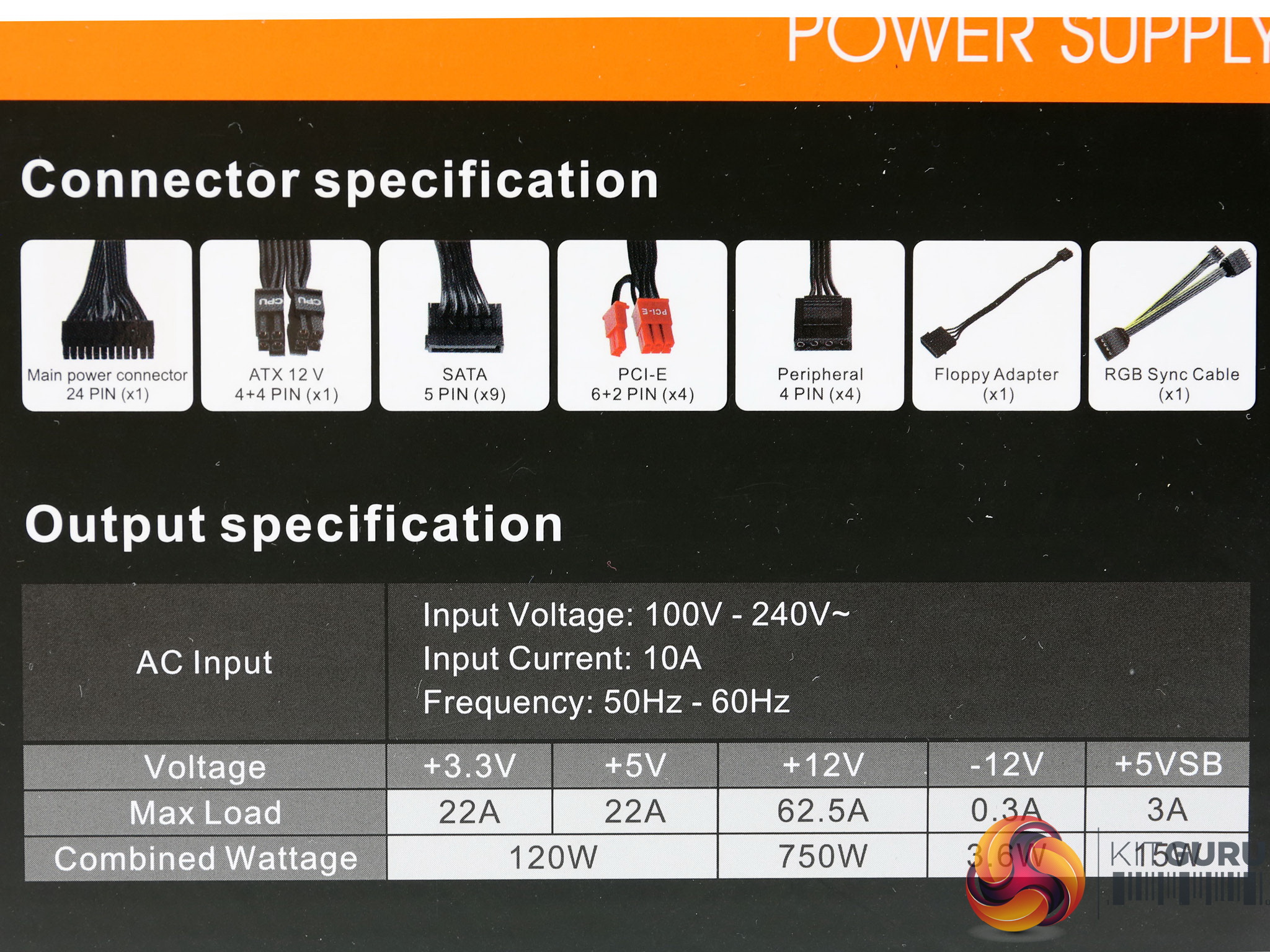
| Rail | 3.3V | 5V | 12V | 5VSB | -12V | |
| Max. Power | Amps | 22 | 22 | 62.5 | 3 | 0.3 |
| Watts | 120 | 750 | 15 | 3.6 | ||
| Total Max. Power (W) | 750 | |||||
The minor rails have 120W max combined capacity and the +12V rail can deliver up to 750W. The 5VSB rail has sufficient capacity and nobody cares anymore about the -12V rail, since it isn't used by the majority of mainboards and other PC parts.
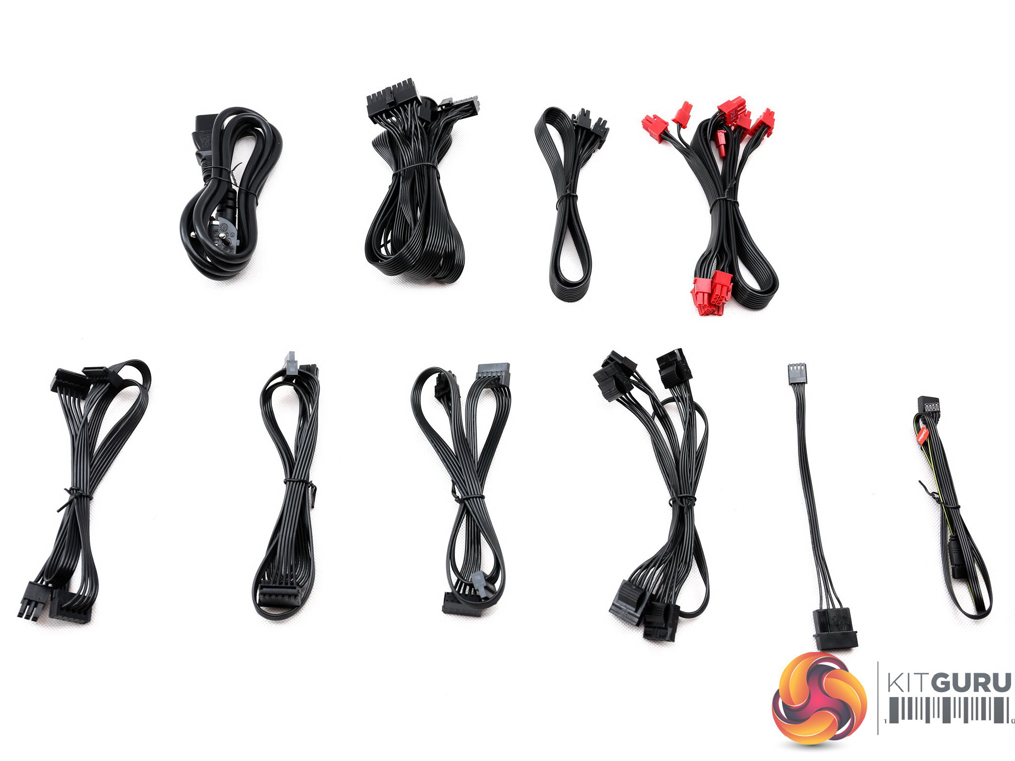
Cables & Connectors
| Modular Cables | ||||
| Description | Cable Count | Connector Count (Total) | Gauge | In Cable Capacitors |
|---|---|---|---|---|
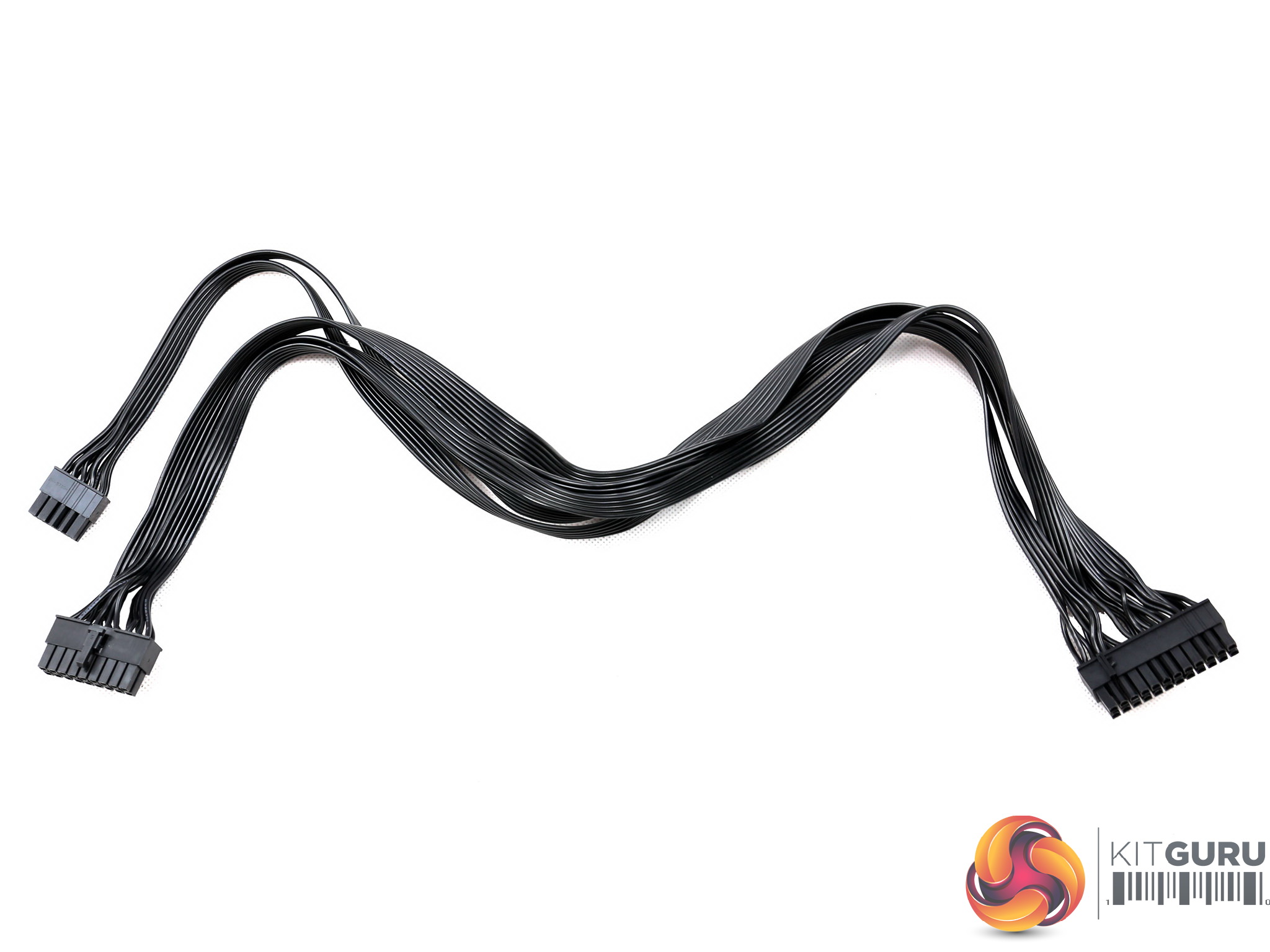
| ATX connector 20+4 pin (600mm) | 1 | 1 | 18AWG | No |
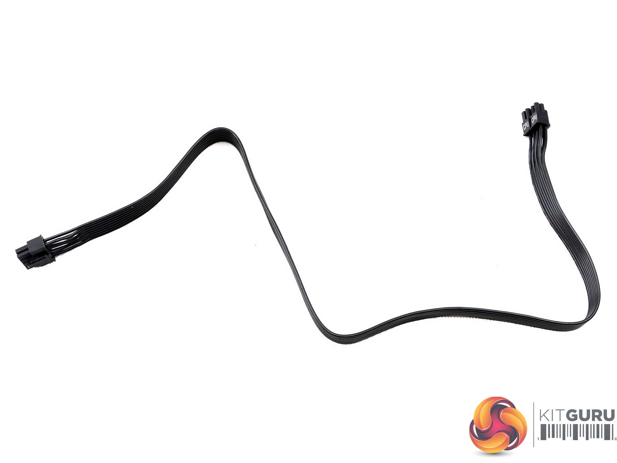
| 4+4 pin EPS12V (660mm) | 1 | 1 | 16AWG | No |
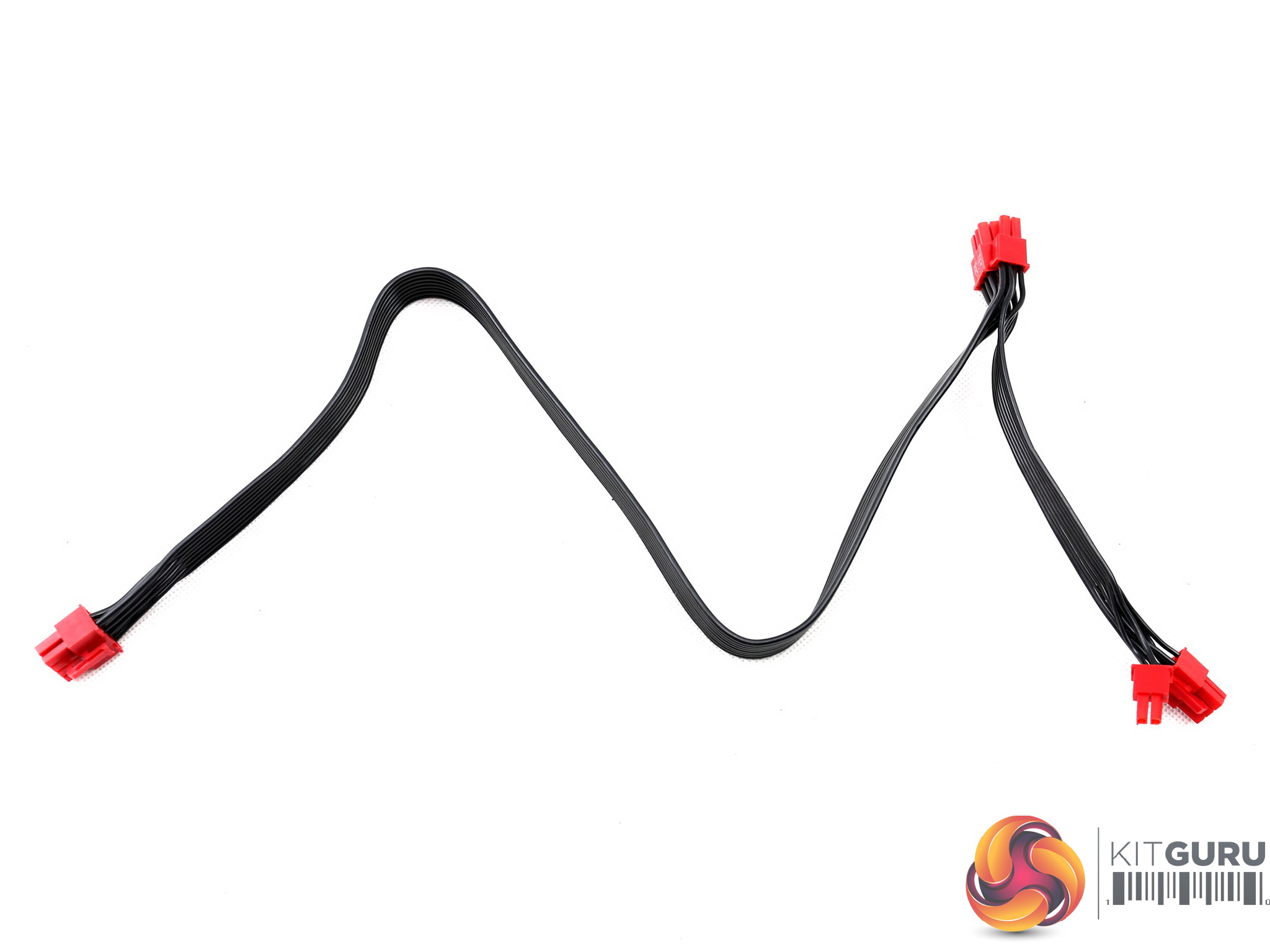
| 6+2 pin PCIe (500mm+155mm) | 2 | 4 | 16-18AWG | No |
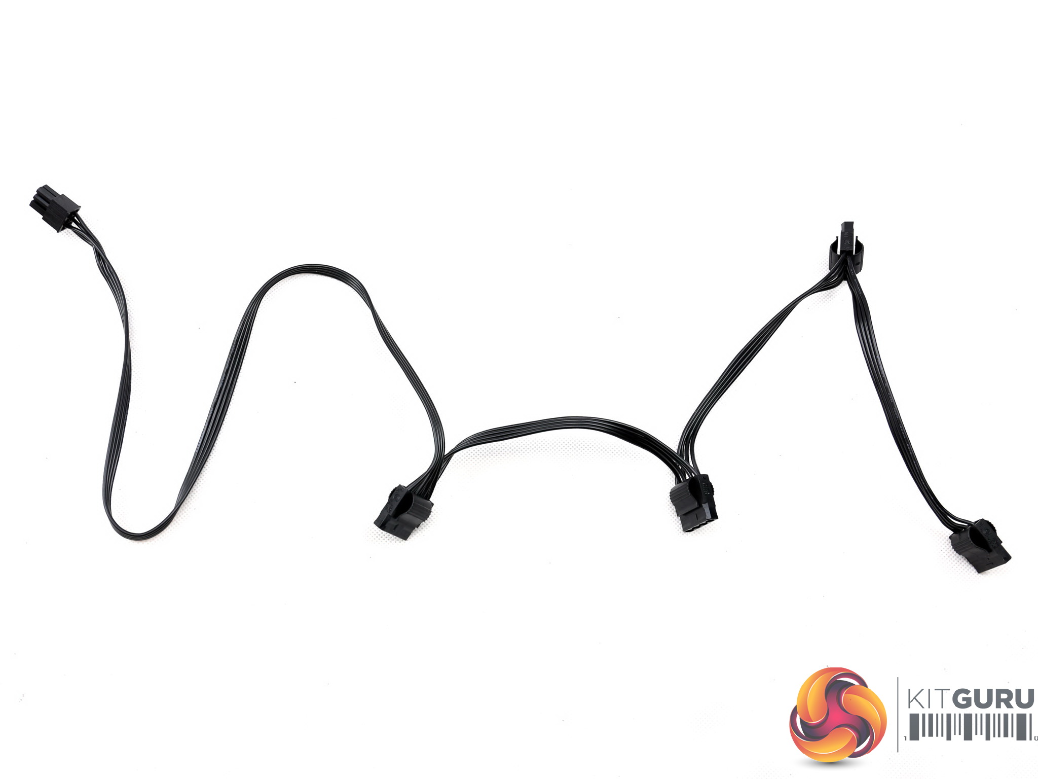
| SATA (510mm+155mm+155mm) | 3 | 9 | 18AWG | No |
| 4-pin Molex (500mm+150mm+150mm+150mm) | 1 | 4 | 18AWG | No |
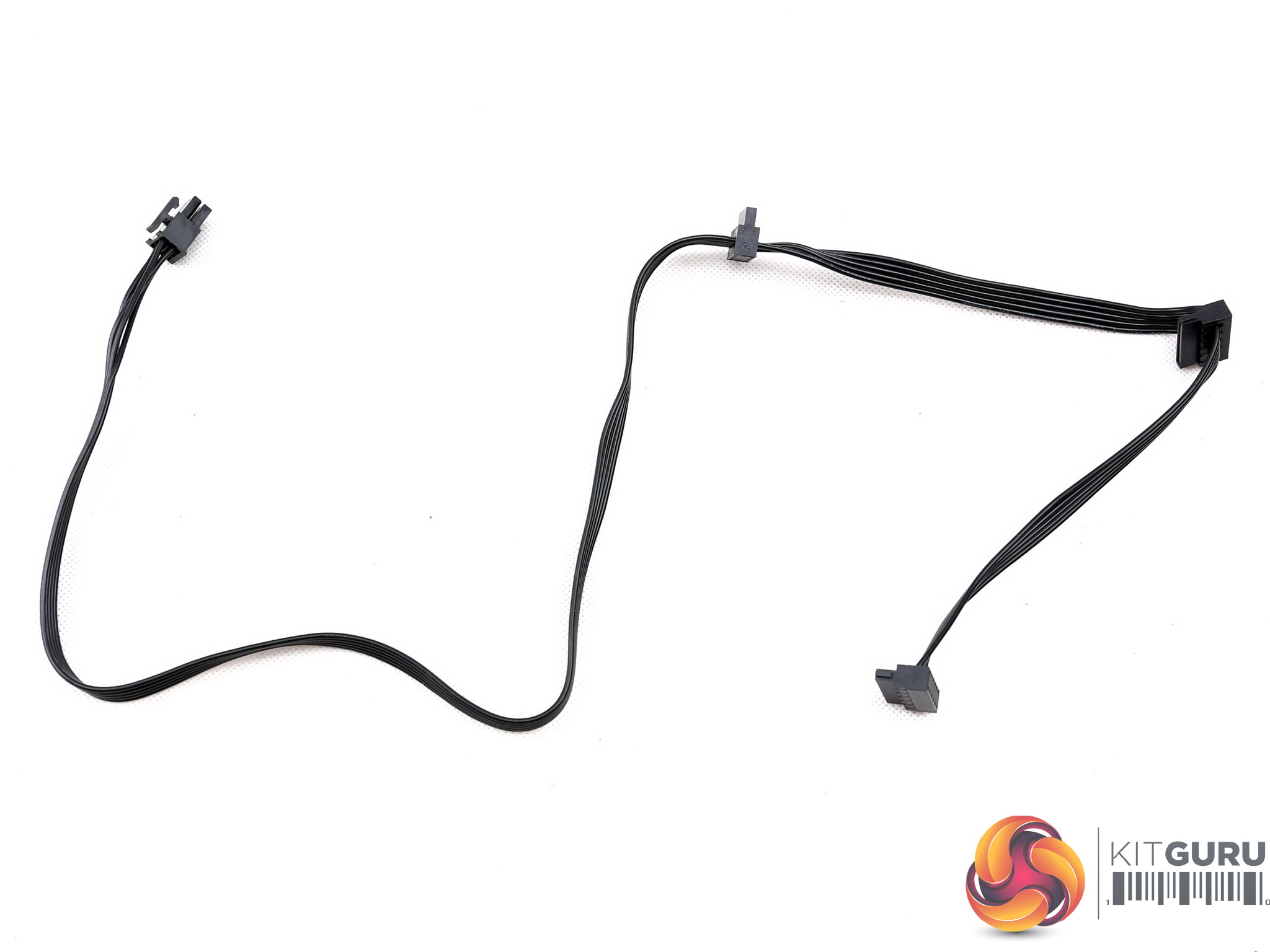
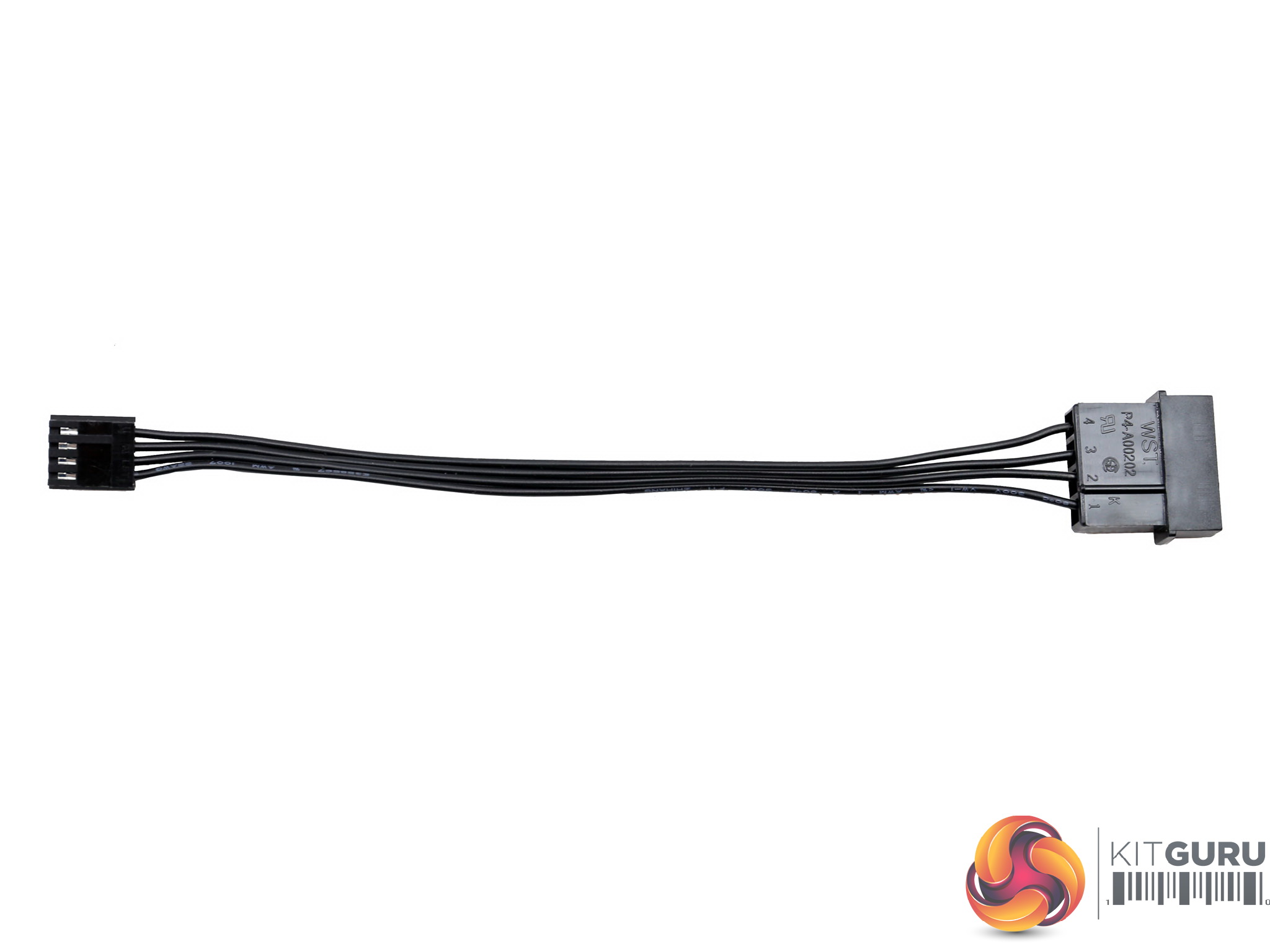
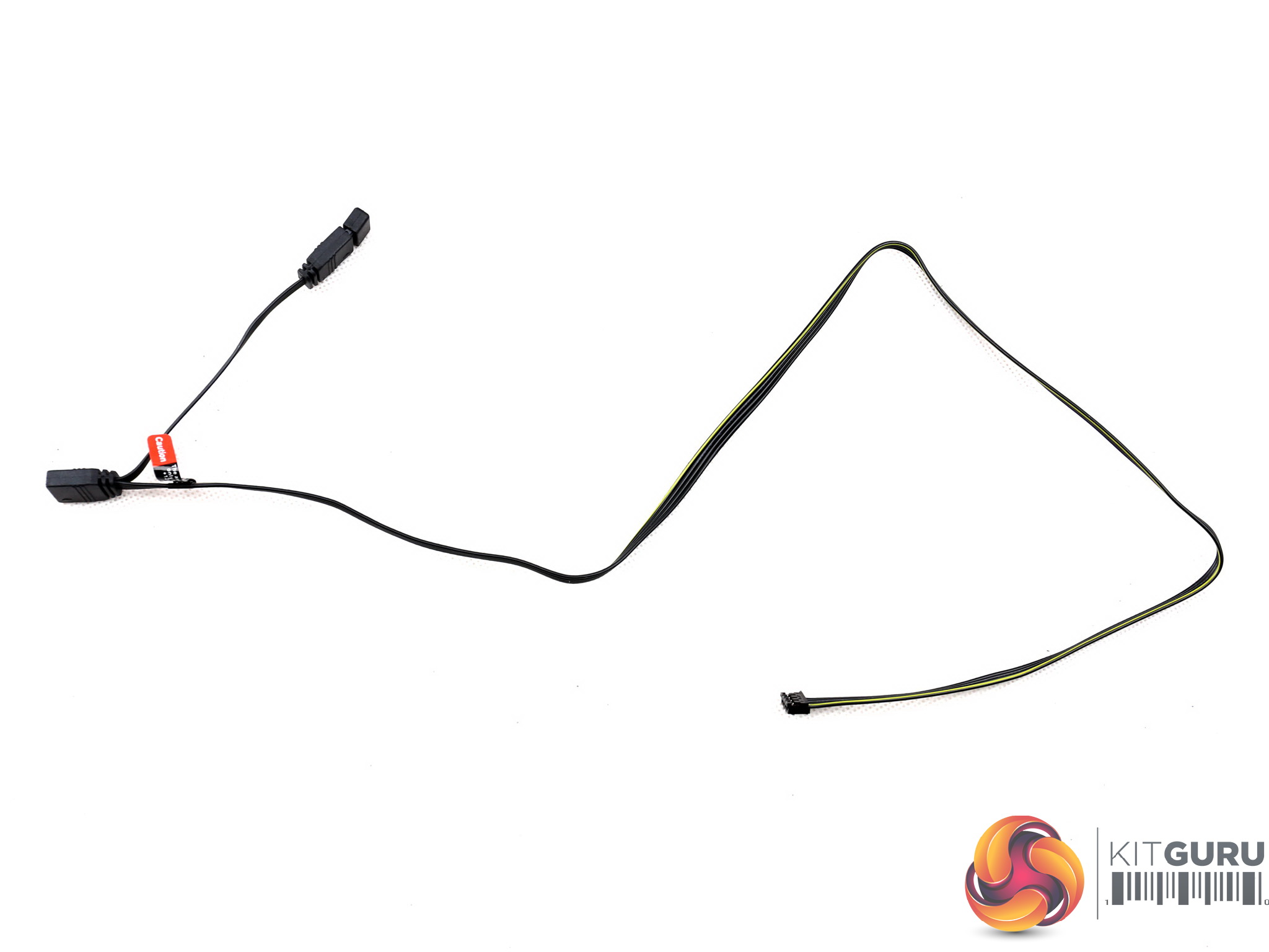
| RGB Cable (580mm+80mm) | 1 | 1 | 26AWG | No |
| FDD Adapter (+160mm) | 1 | 1 | 22AWG | No |
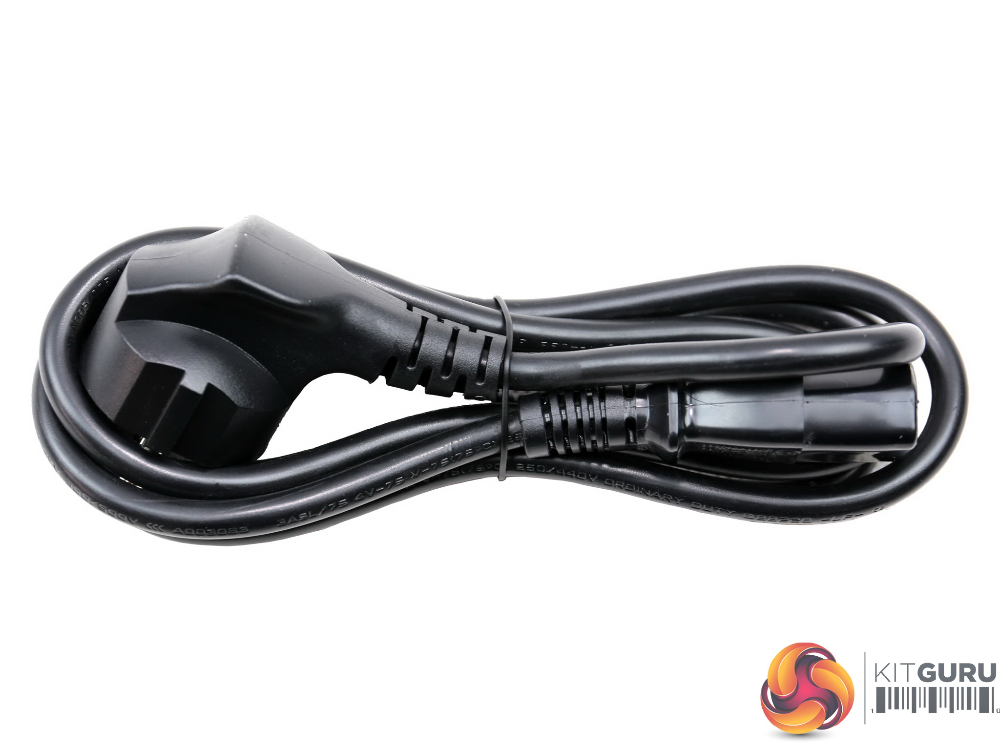
| AC Power Cord (1400mm) – C13 coupler | 1 | 1 | 18AWG | – |
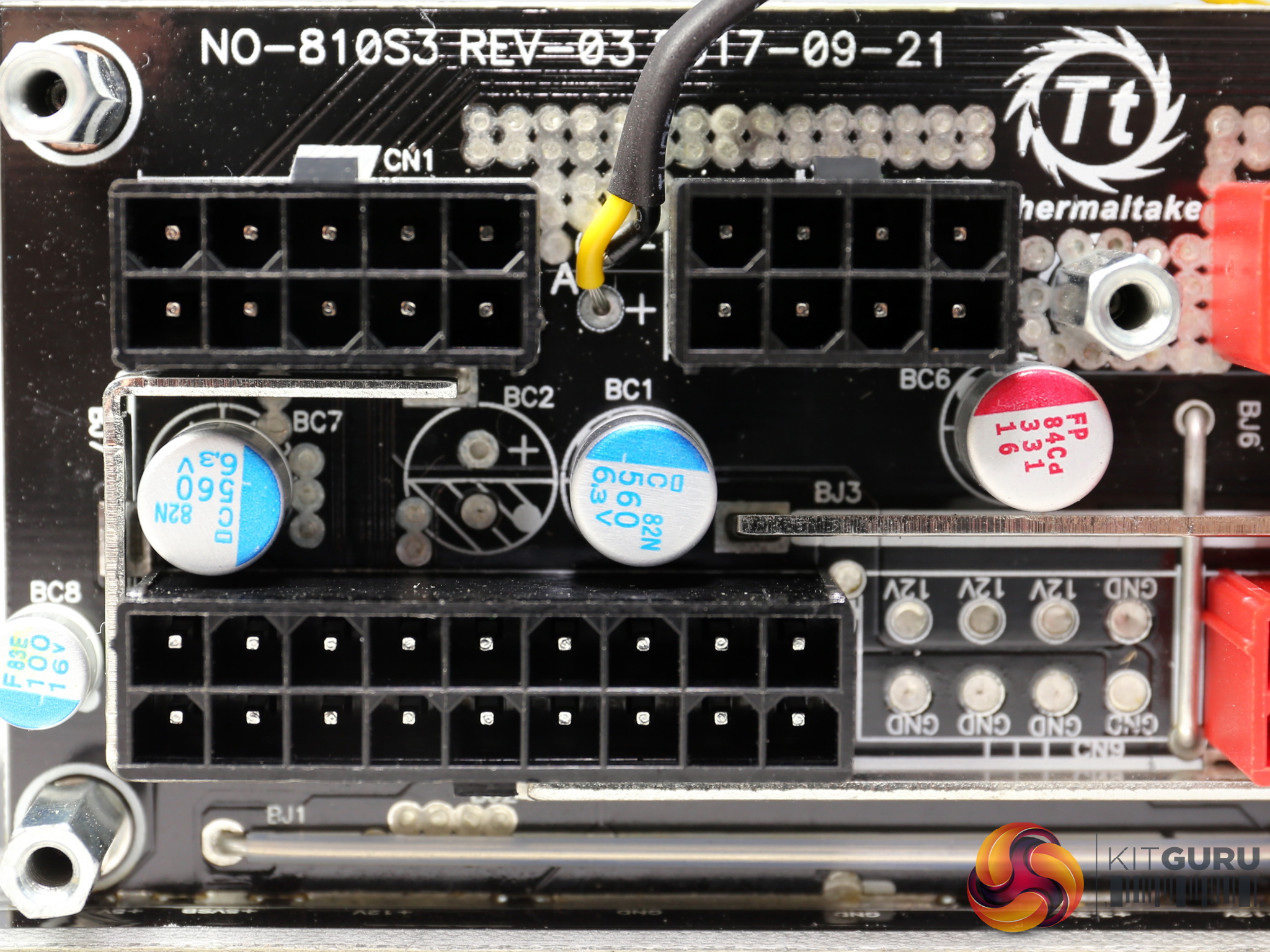
There are no extra filtering caps on the cables, and the distance between the peripheral cables is ideal. What more to ask? Well a second set of EPS connectors would be great, since this is a 750W unit which most likely will be combined with a high-end mainboard, requiring increased power in the CPU socket area.
Dual EPS connectors are not completely necessary however some high end boards including all that support AMD Threadripper processors will need them. It is a huge mistake to cripple this units usability by providing only one EPS connector. On the other hand, the number of PCIe and peripheral connectors is satisfactory.
Packaging
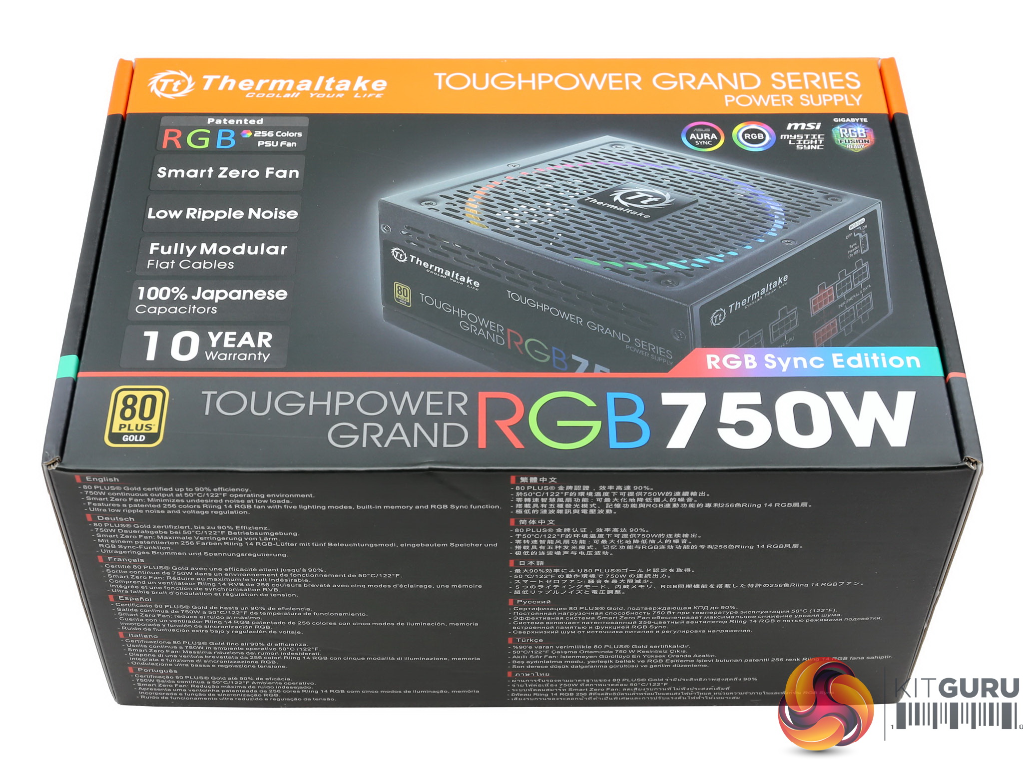
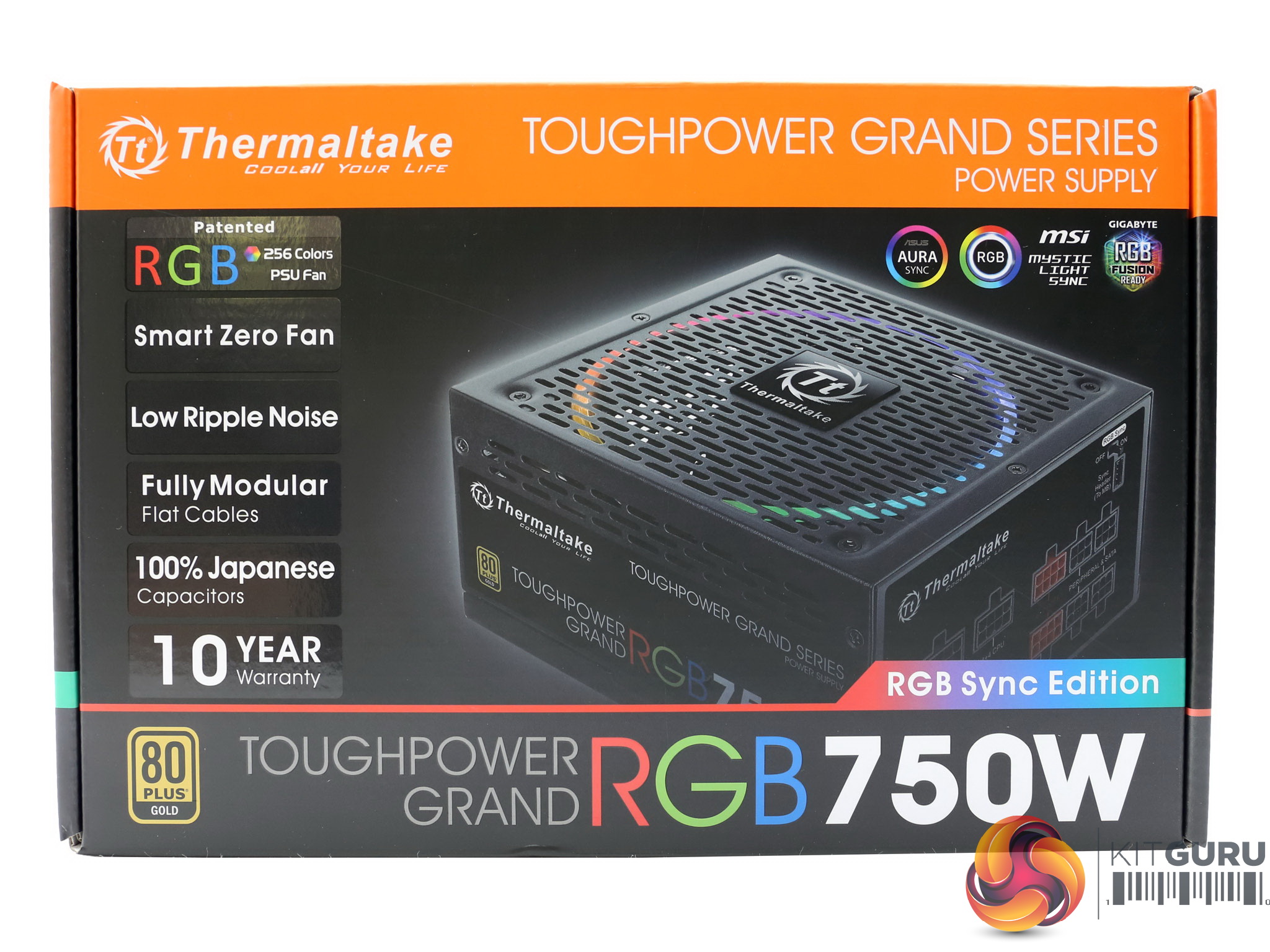
As usually is the case with Thermaltake products, the box features a fancy and colorful design. At its face the series description along with the unit's max power and its major features, are depicted. The 80 PLUS Gold badge is in the bottom-left corner and there is also a photo of the PSU with the fan's RGB lighting in operation.
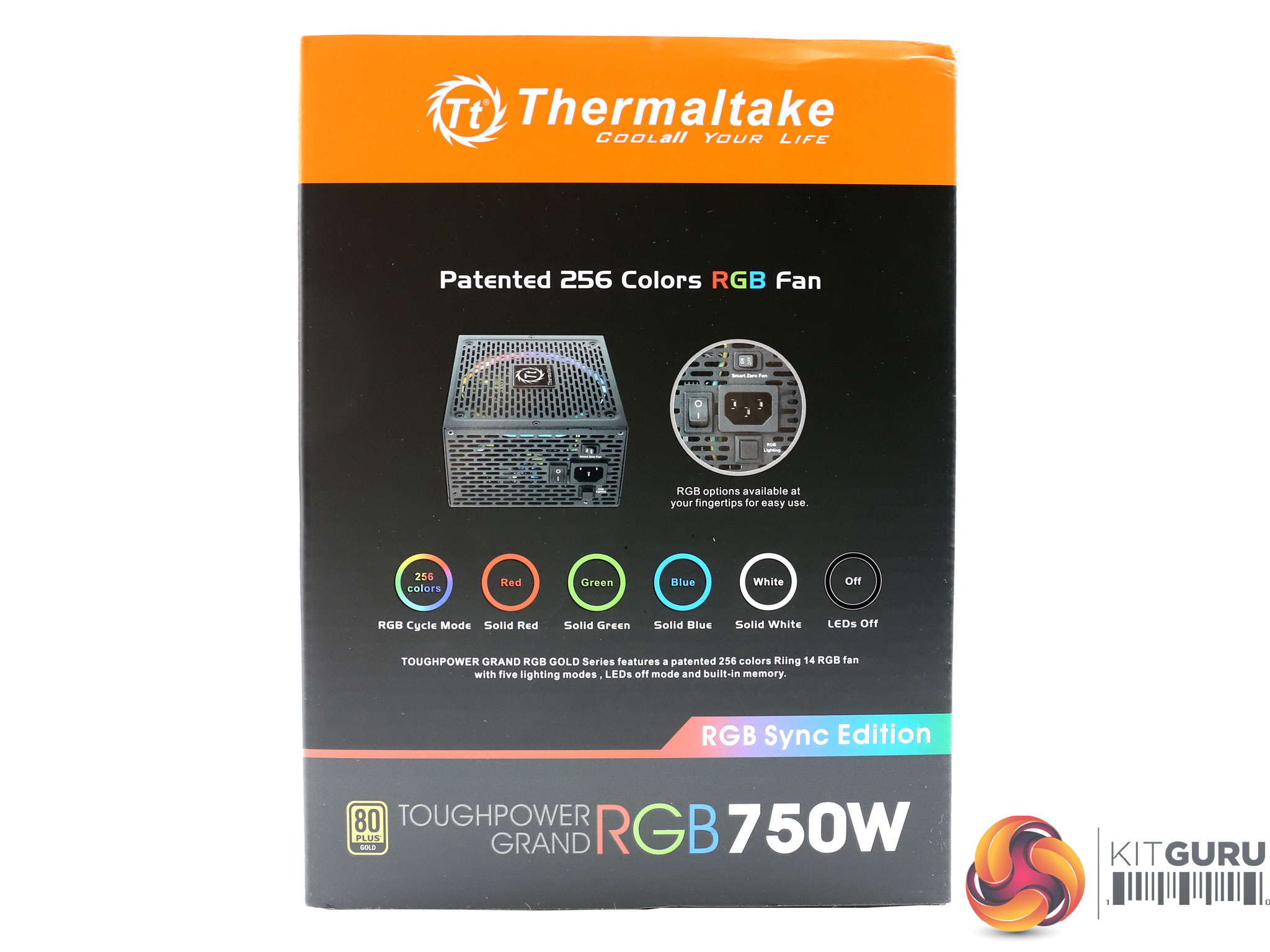
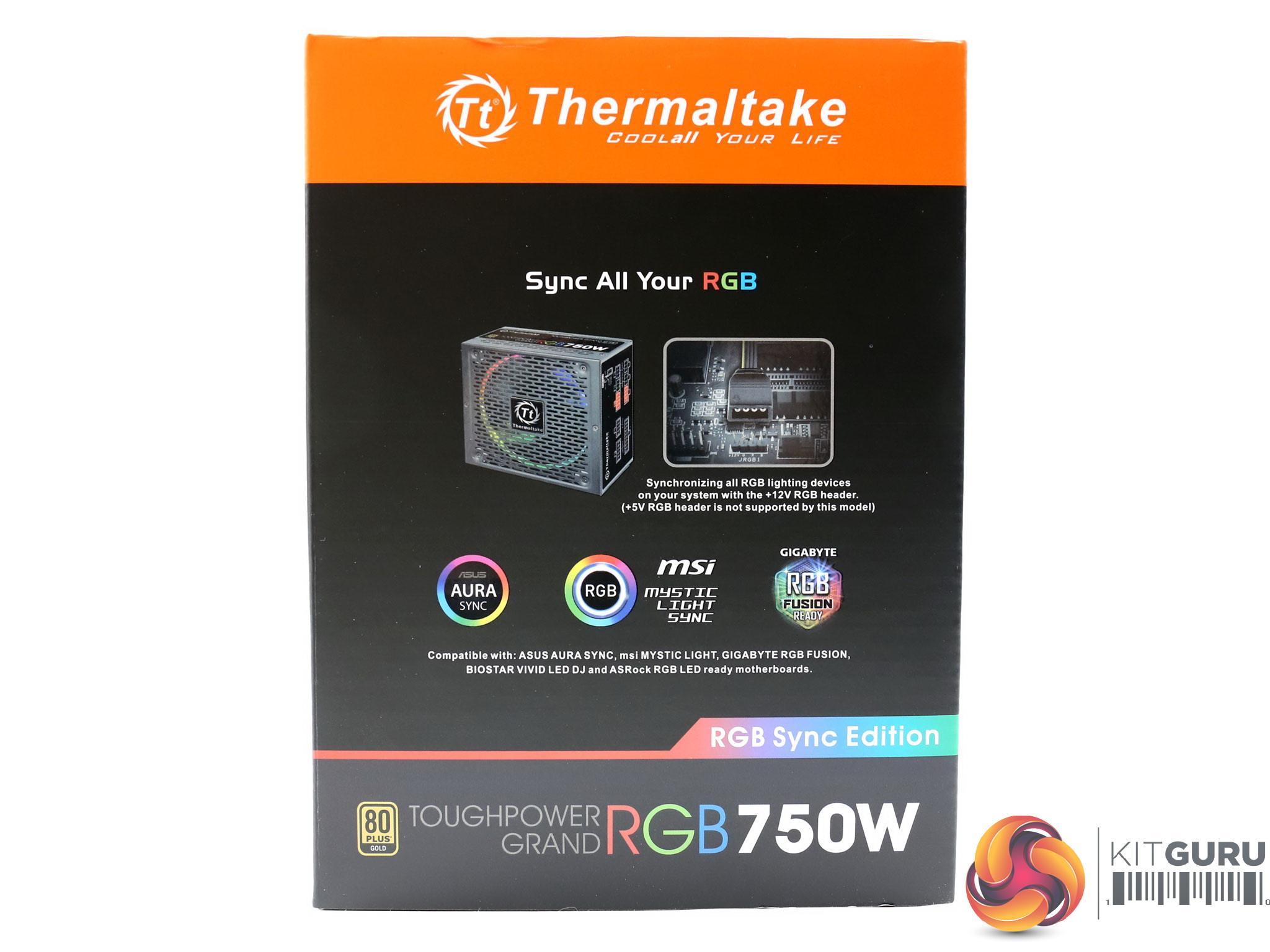
The RGB color modes are described on one side of the box, while on the other one you will find out the compatible applications from major mainboard manufacturers.
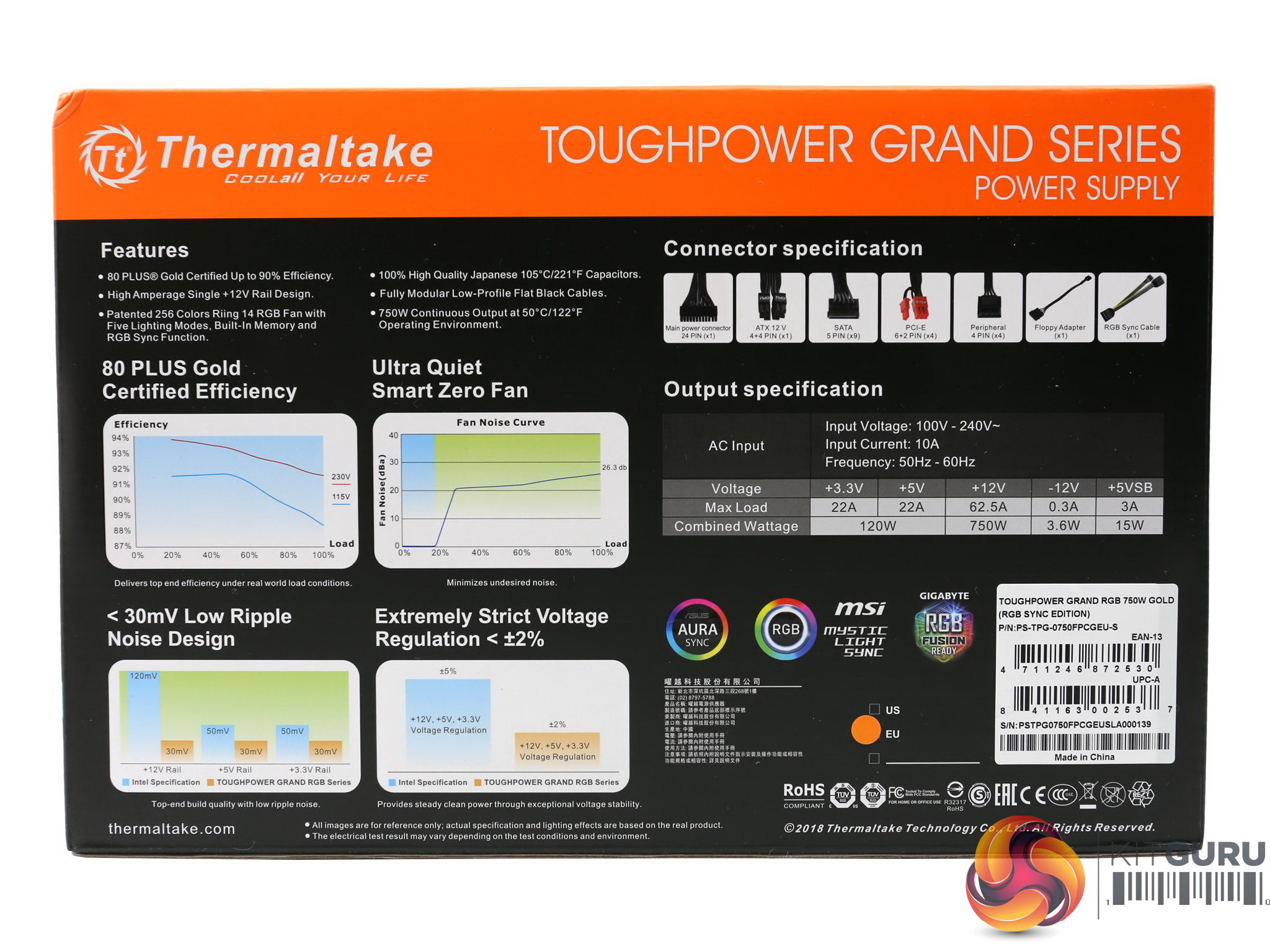
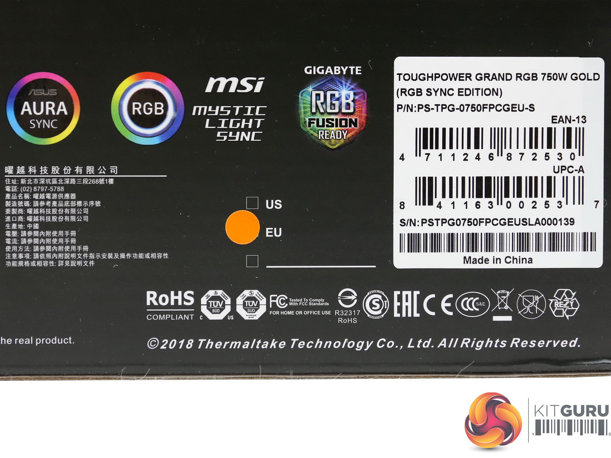
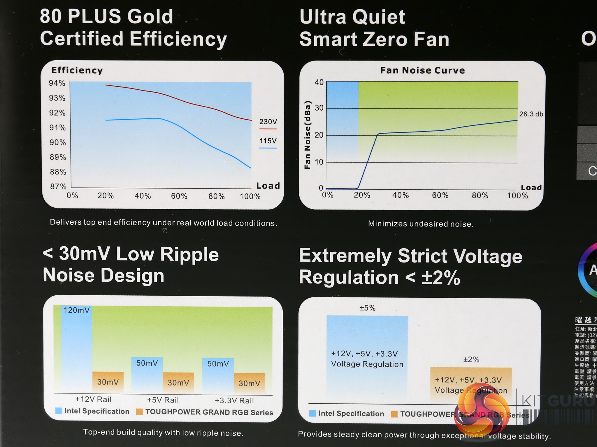
Besides the power specifications table at the rear side you will also find a list showing the available connectors, along with a pair of graphs depicting the unit's efficiency, noise output. The part and serial numbers are written on a large sticker, along with the manufacturing country which is China, of course.
Contents
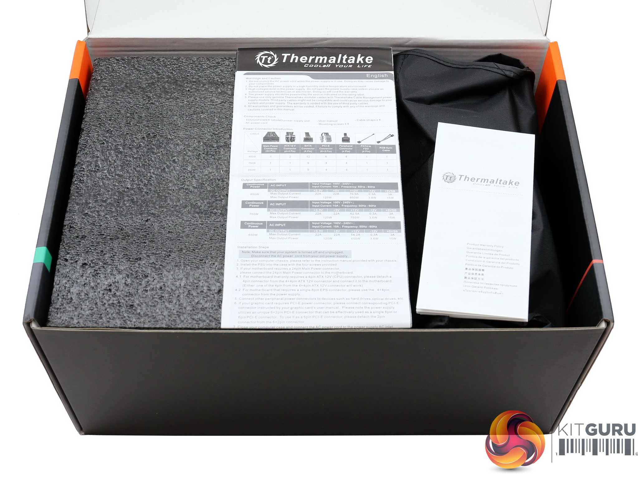
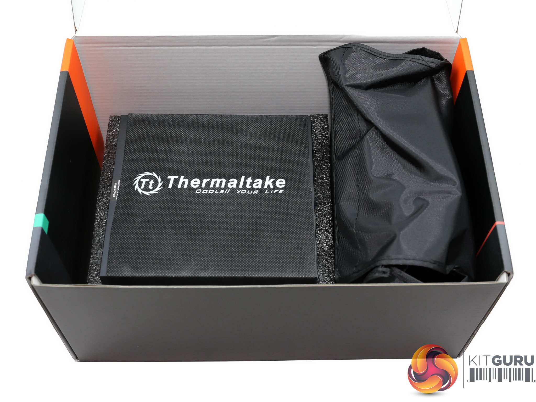
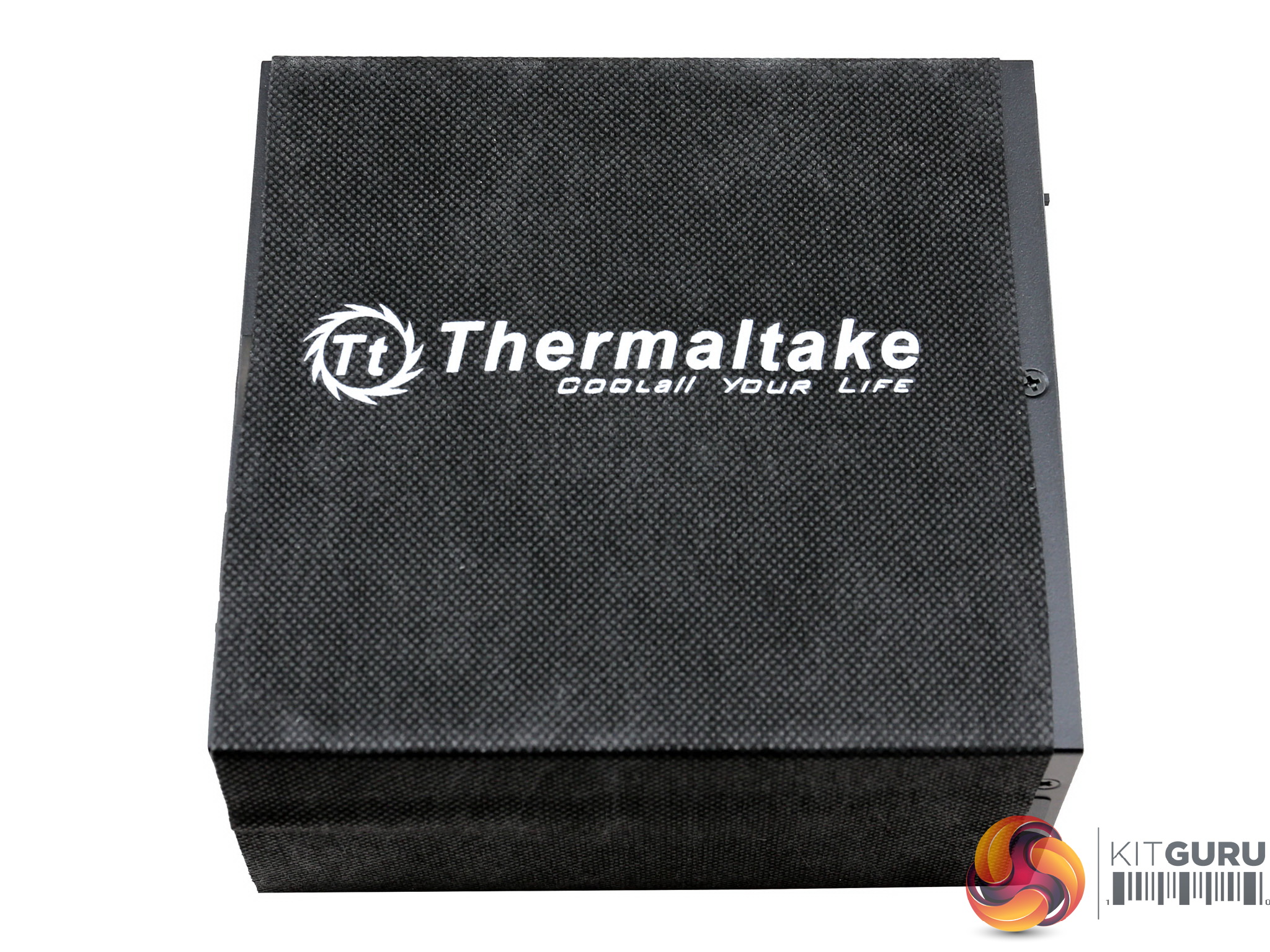
The packing protection inside the box is good, with the power supply wrapped into a nice cloth cover.
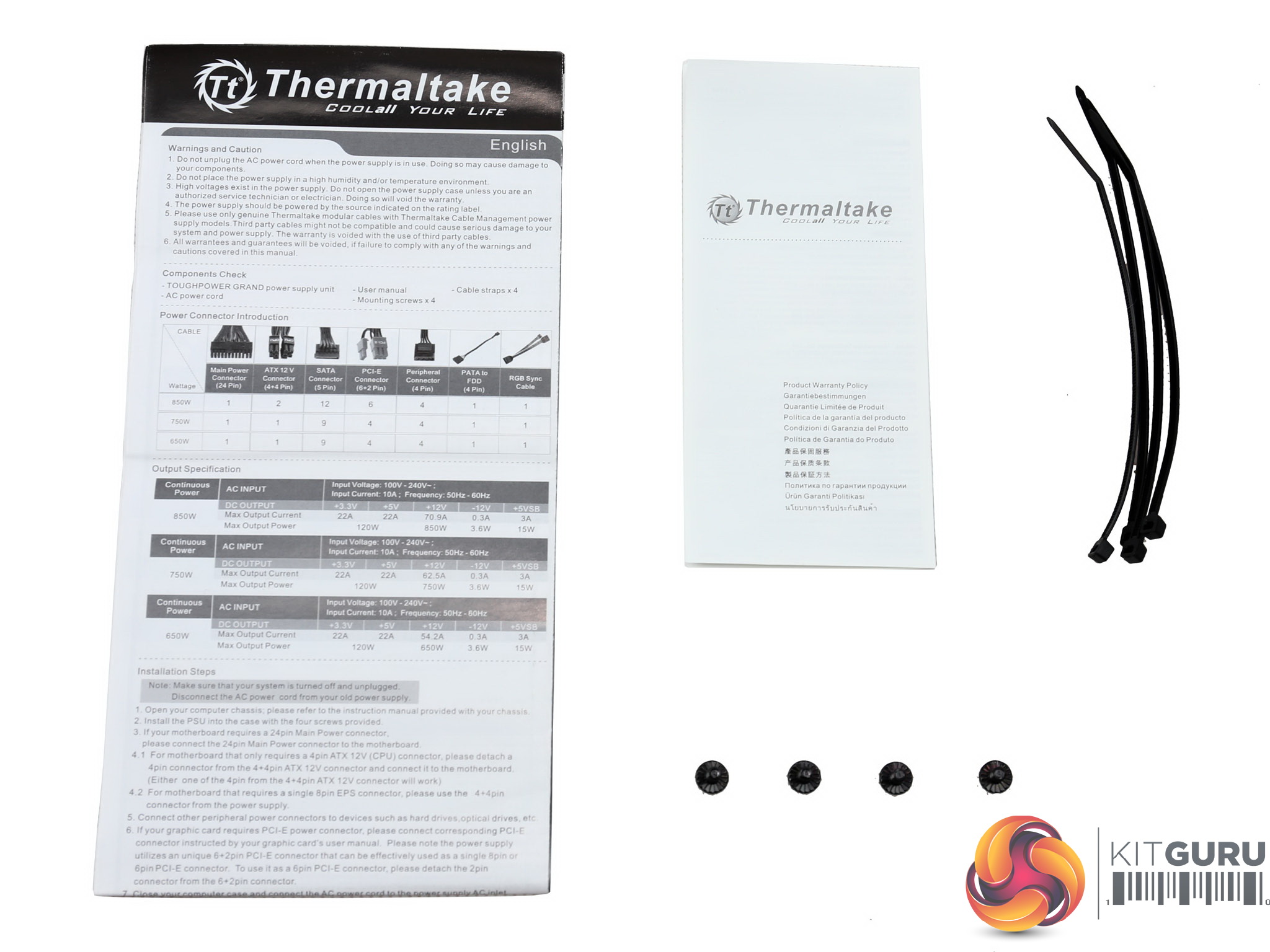
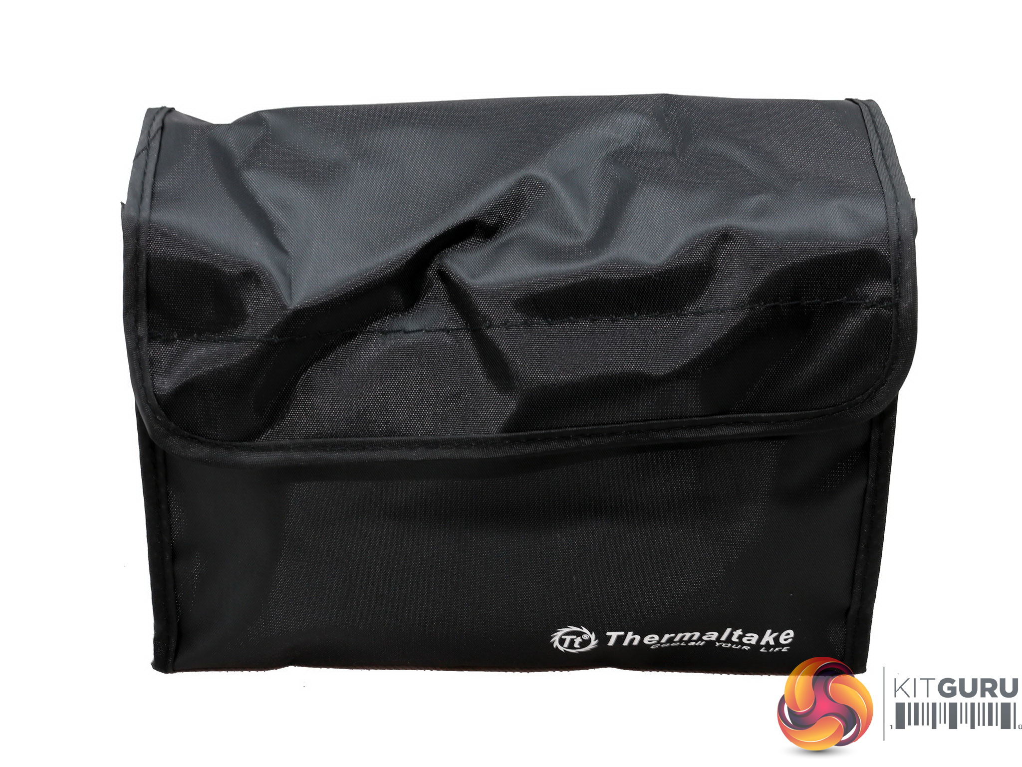
The bundle includes a number of zip ties, four screws for mounting the PSU onto the chassis, the user's manual and a warranty leaflet. There is also a pouch provided, for storing the unused modular cables.
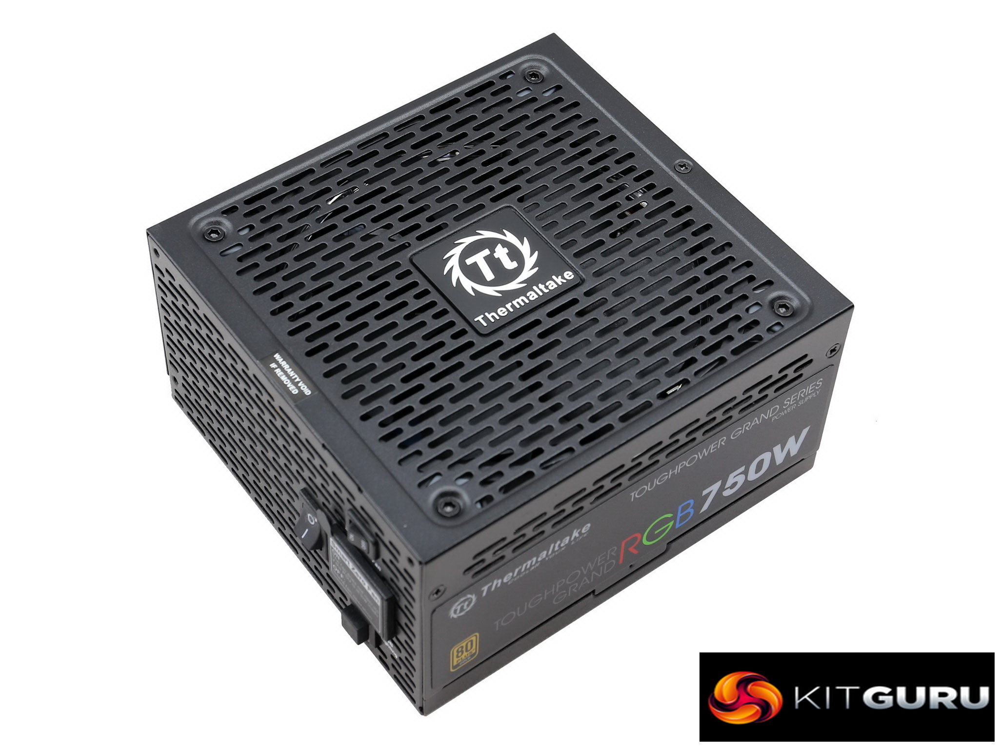
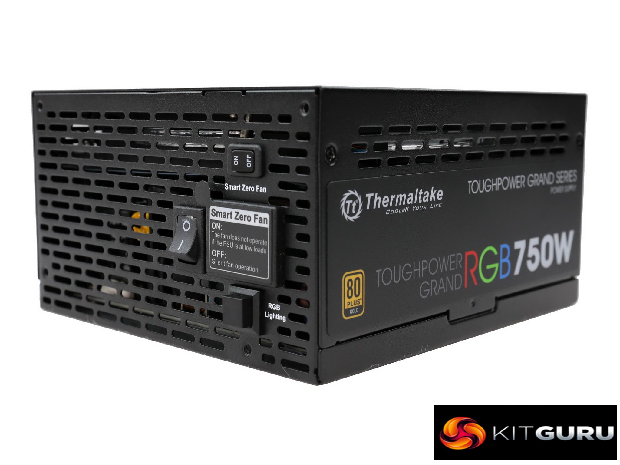
Exterior
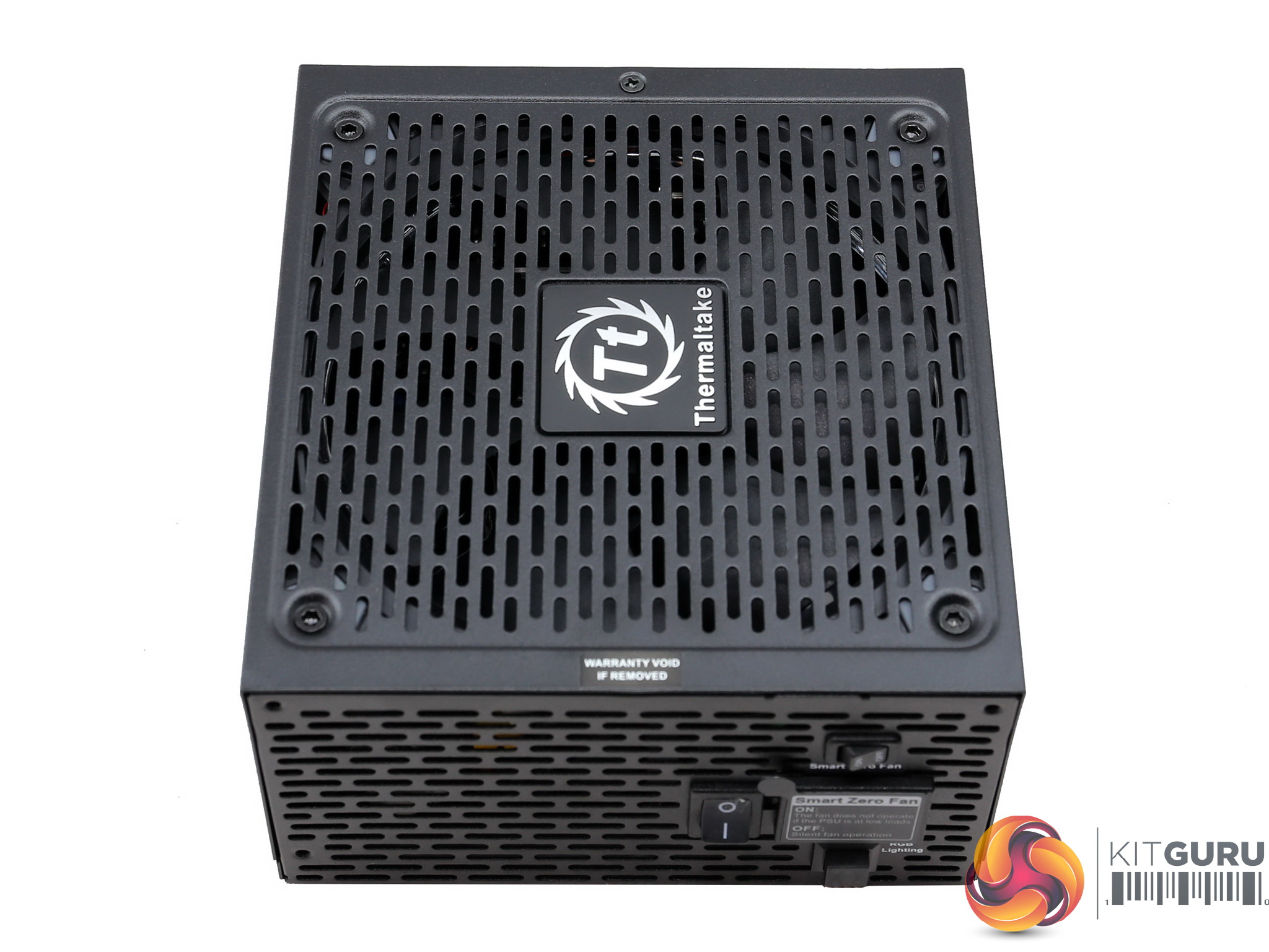
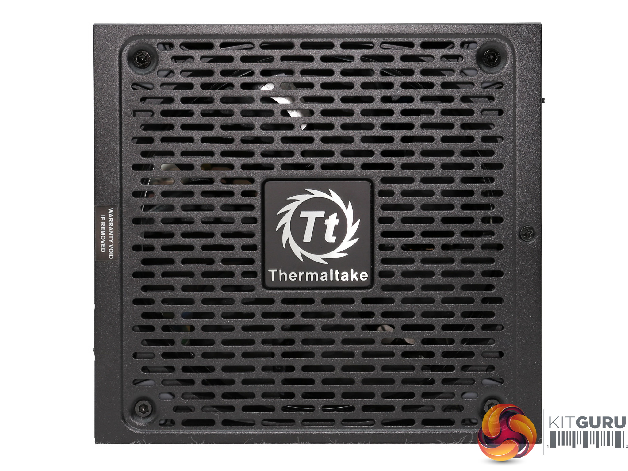
Thermaltake uses a unique design, which differentiates its power supplies from other offerings. This is a nice looking product, for those who actually care about their power supplies appearance.
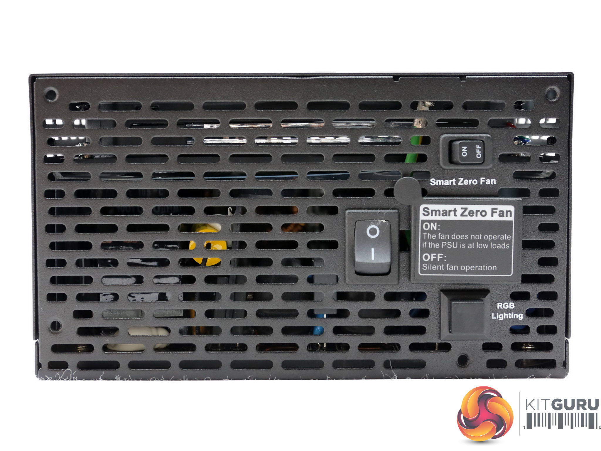
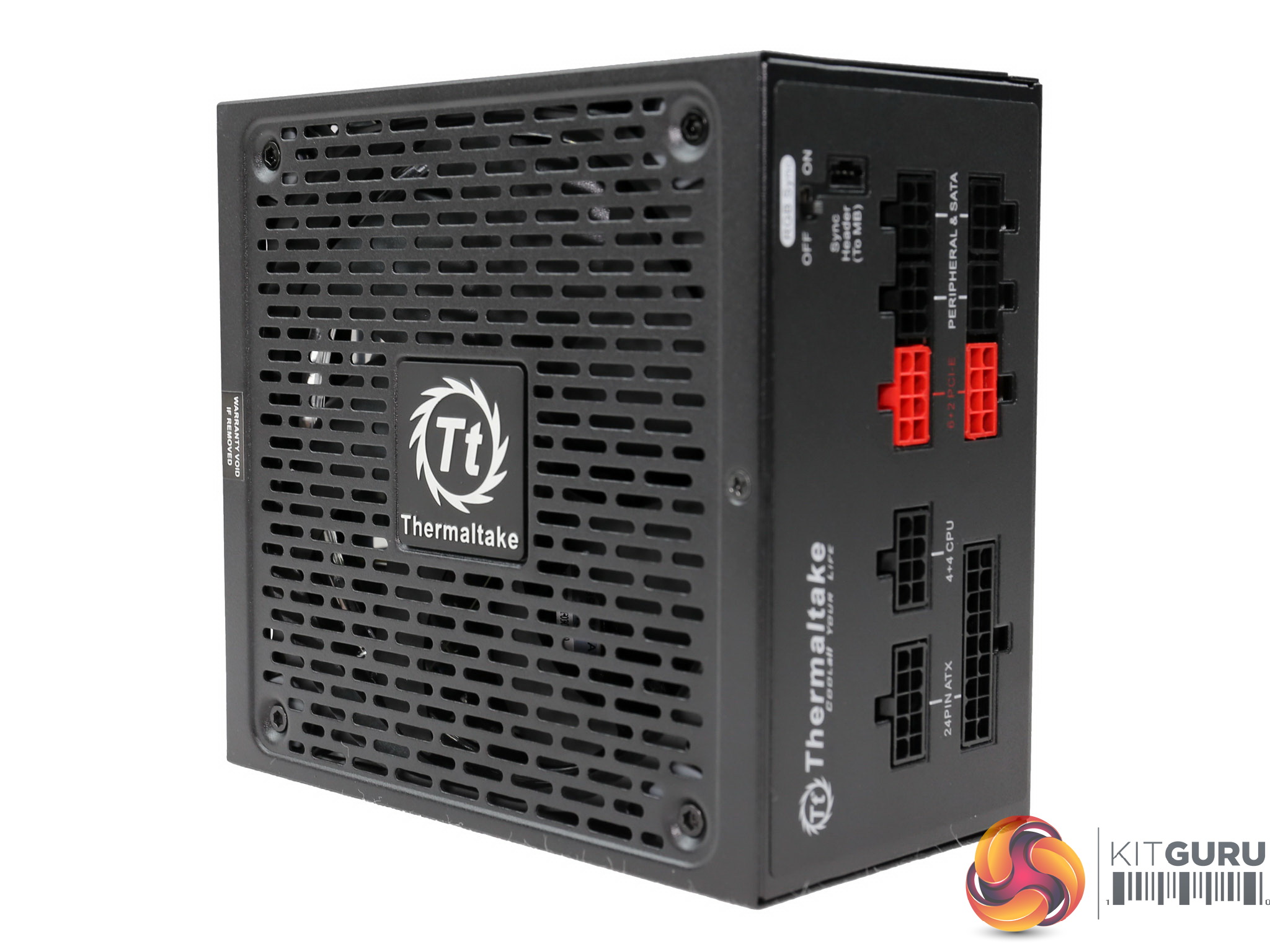
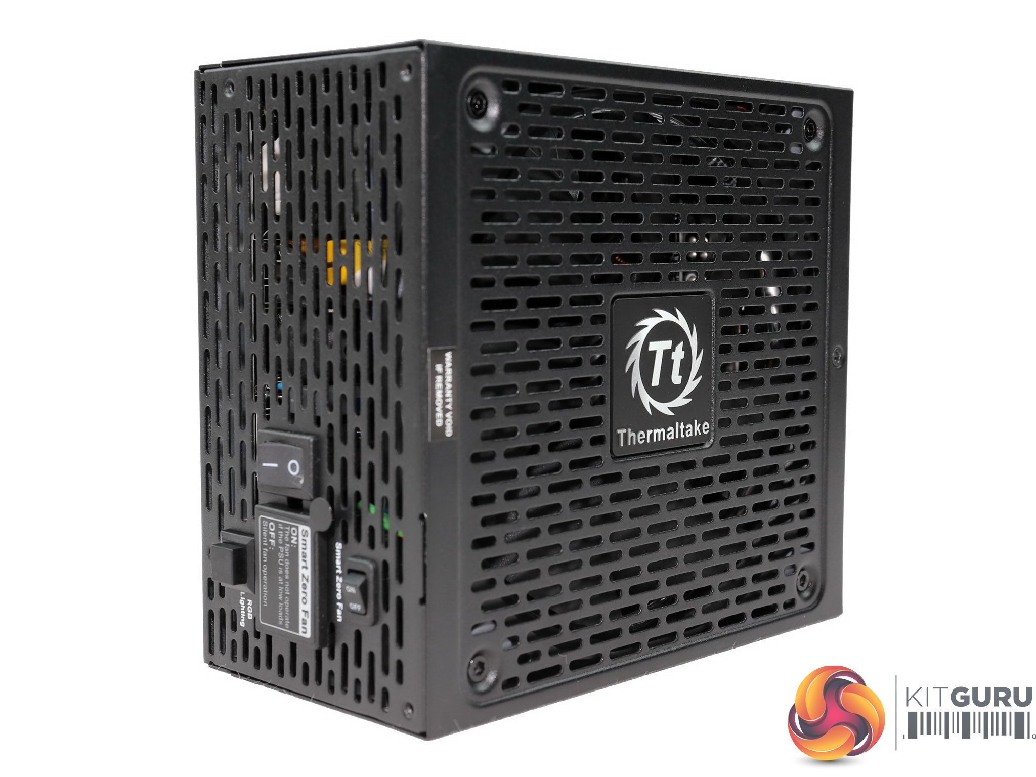
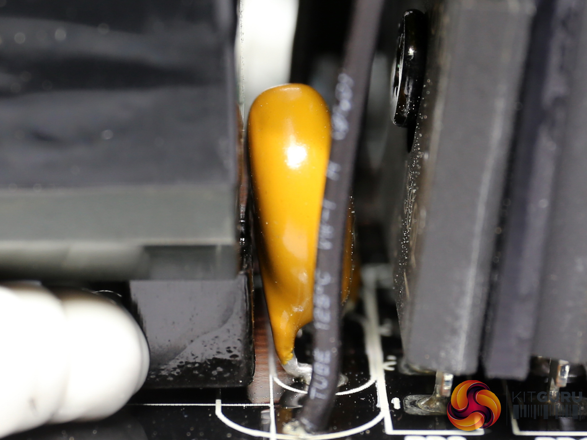
At the front besides the power switch there is also a smaller switch for toggling on/off the semi-passive operation along with a push button, for manually setting the RGB lighting. A sticker covers the AC receptacle, informing about the semi-passive operation.
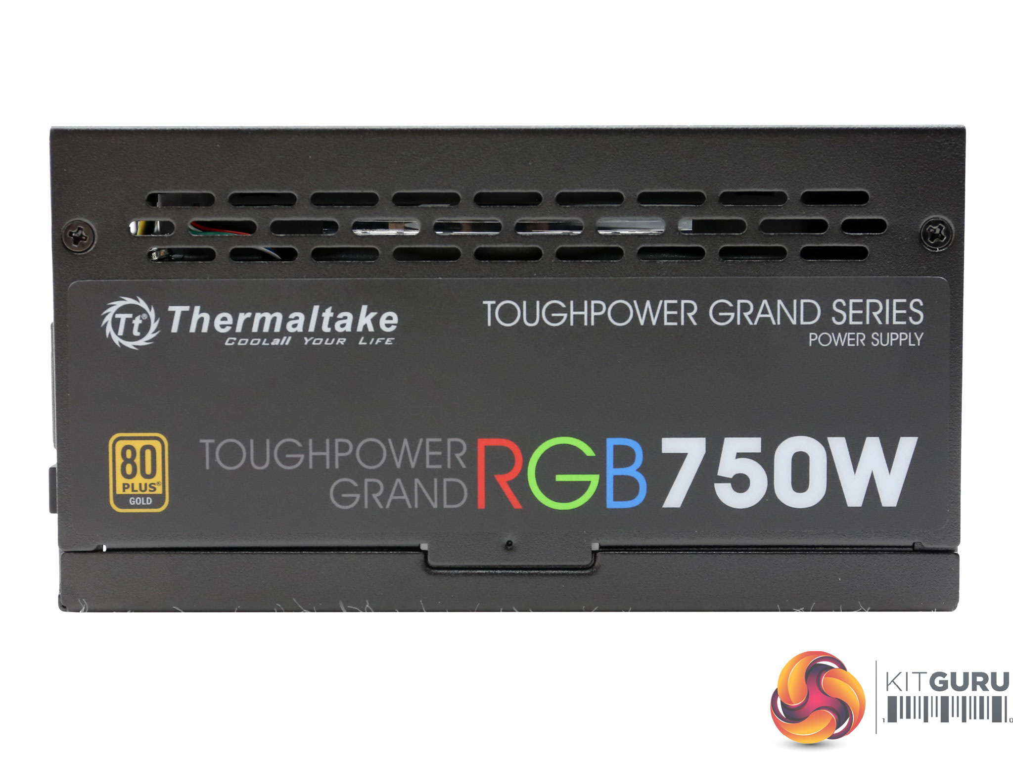
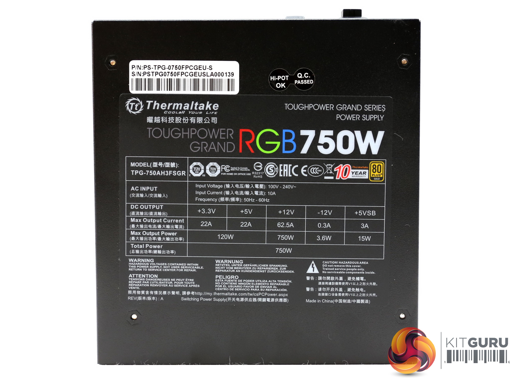
On the sides the stickers depict the series and model descriptions along with the 80 PLUS badge. The power specifications label, which also includes the serial and part numbers, is installed at the bottom.
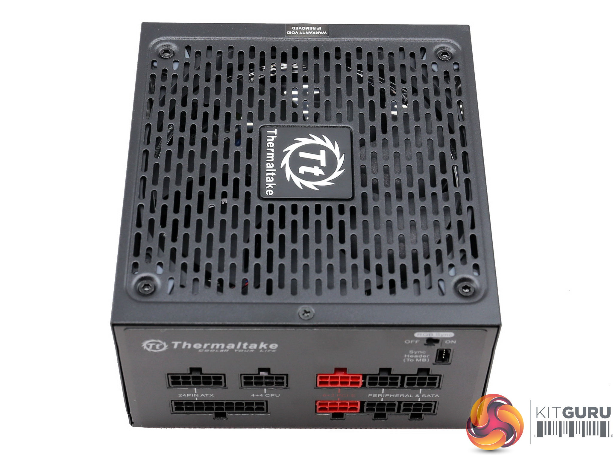
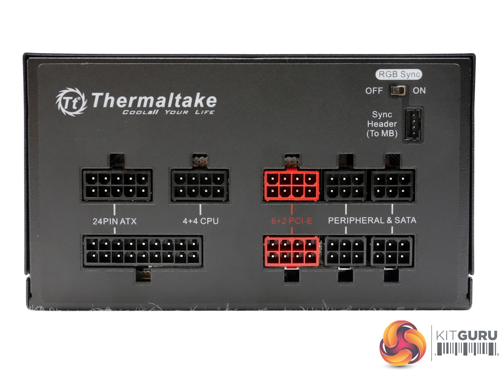
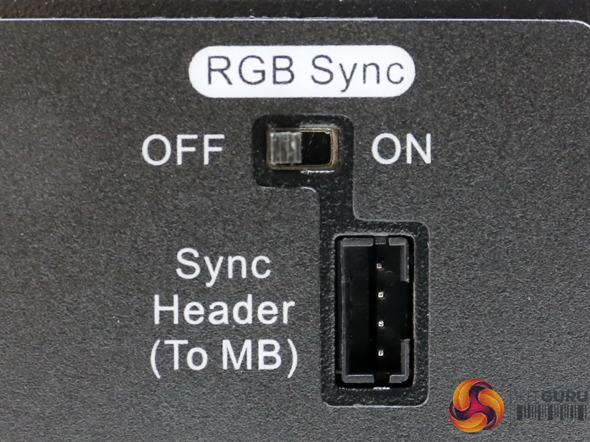
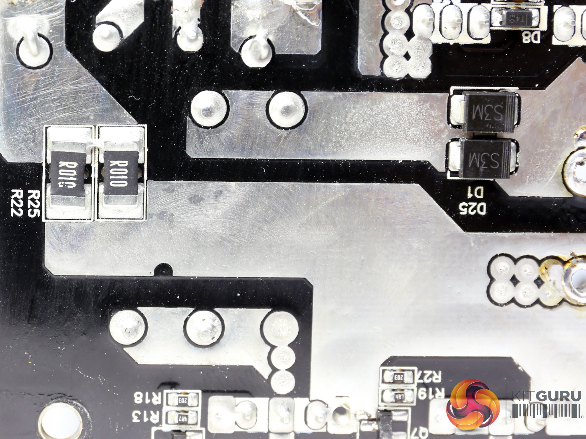
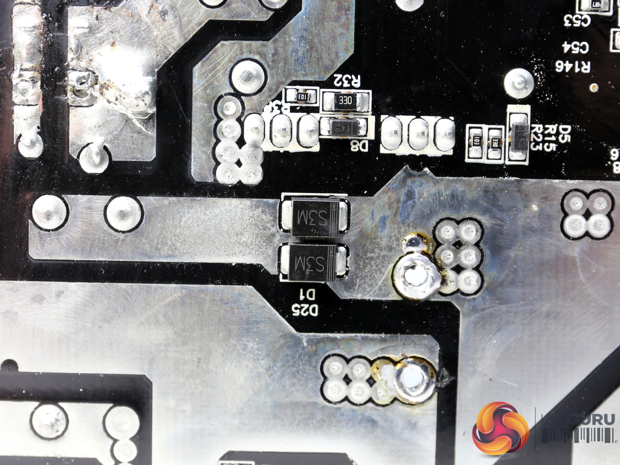
There are not many sockets. Normally Thermaltake would have included a second EPS socket, to provide two of those connectors in total. The red sockets are for the PCIe connectors. There is also a socket for the RGB sync cable, which goes to the mainboard along with a switch for enabling/disabling this feature.
A disturbing detail here is that the EPS and PCIe sockets are identical, so if you don't pay any attention to the red sockets and connect a PCIe cable to the EPS socket, the PSU won't start since the short circuit protection will kick in. We know that the red sockets are there for a reason, however normally the EPS and PCIe connectors would have a different layout. I don't really like this design decision at all.
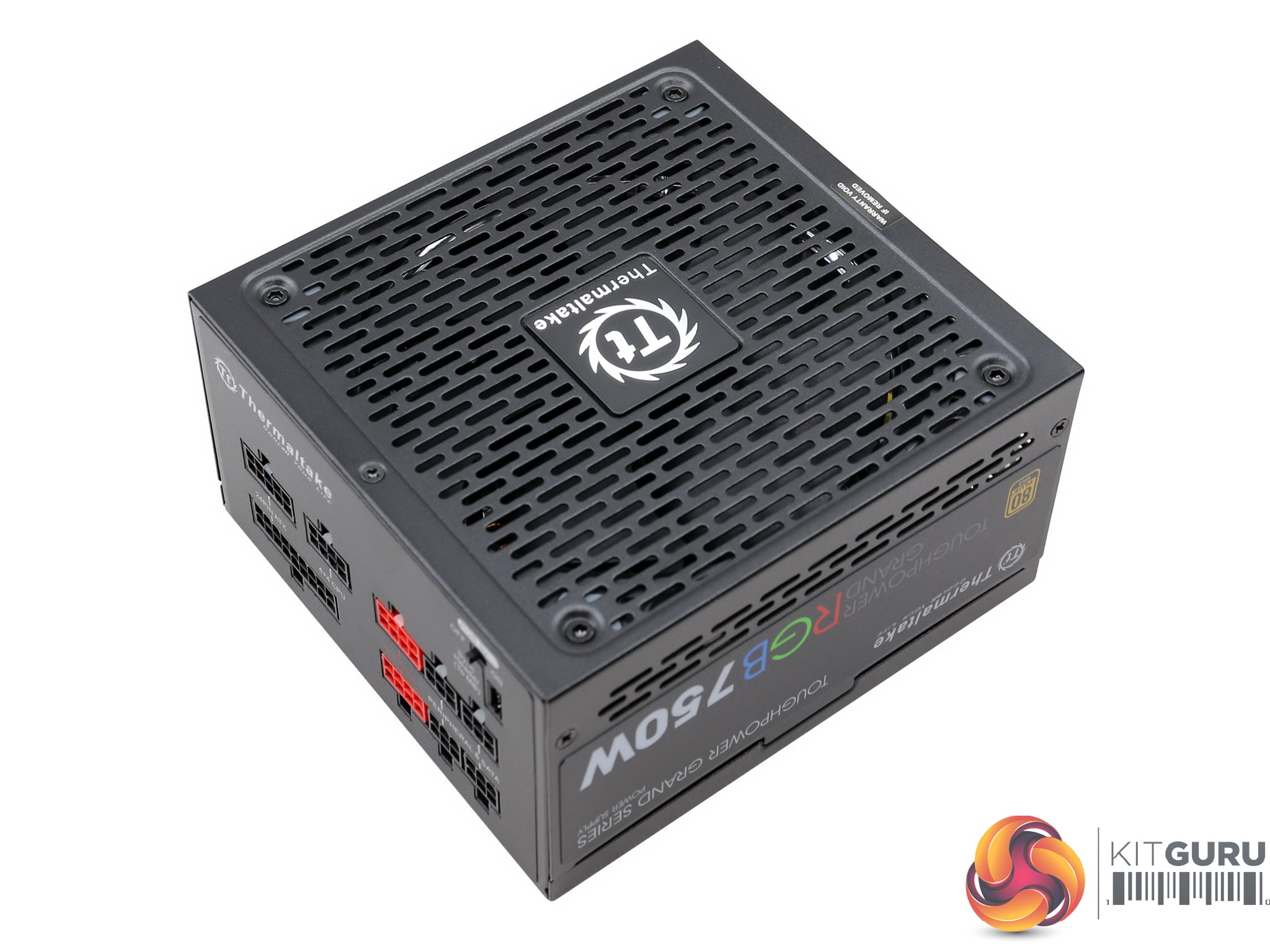

The dimensions are small and the fan covers almost the entire top side of the unit.
| General Data | |
| Manufacturer (OEM) | Sirfa / High Power |
| Primary Side | |
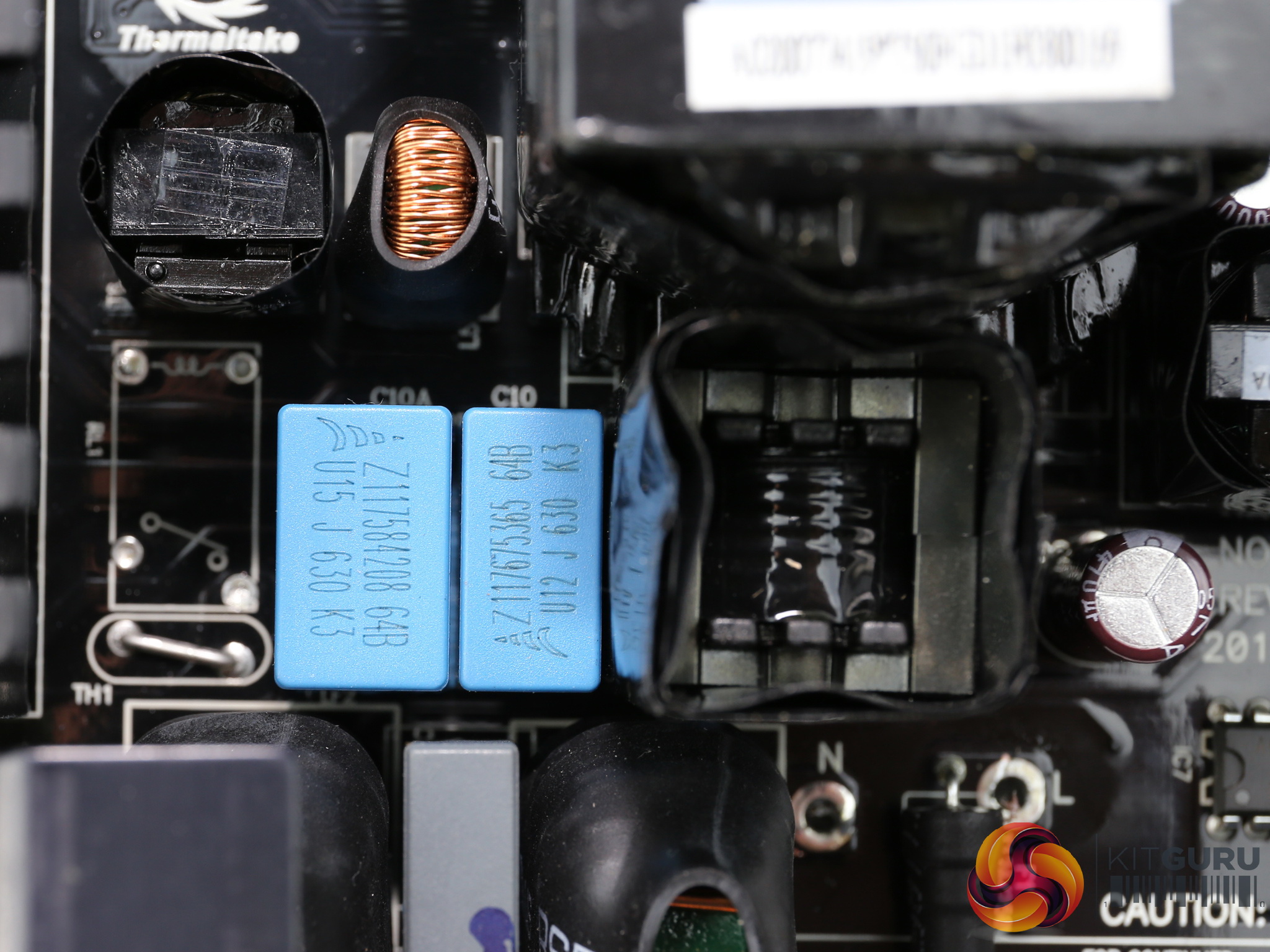
| Transient Filter | 4x Y caps, 2x X caps, 2x CM chokes, 1x MOV |
| Inrush Protection | NTC Thermistor & Relay |
| Bridge Rectifier(s) |
2x GBU1506 (600V, 10A @ 100°C)
|
| APFC MOSFETS |
2x China Wind CWS20N60AF (600V, 13A @ 100°C, 0.19Ohm)
|
| APFC Boost Diode |
1x UnitedSiC UJD06506TS (650V, 6A @ 153°C)
|
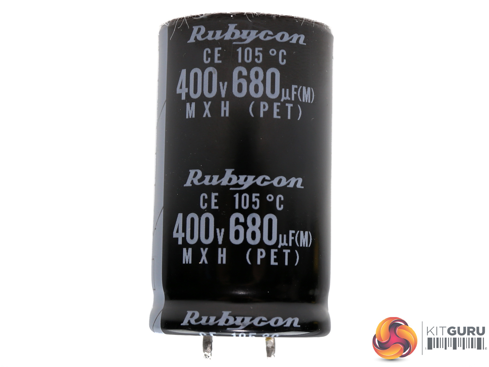
| Hold-up Cap(s) |
1x Rubycon (400V, 680uF, 2000h @ 105 °C, MXH)
|
| Main Switchers |
2x China Wind CWS20N60AF (600V, 13A @ 100°C, 0.19Ohm)
|
| APFC Controller |
Infineon ICE3PCS01G
|
| Resonant Controller | Champion CM6901X |
| Topology |
Primary side: Half-Bridge & LLC Resonant Controller
Secondary side: Synchronous Rectification & DC-DC converters |
| Secondary Side | |
| +12V MOSFETS | 6x Infineon BSC027N04LS G (40V, 88A @ 100°C, 2.7mOhm) |
| 5V & 3.3V | DC-DC Converters: 6x Infineon BSC0906NS (30V, 40A @ 100°C, 4.5mOhm) PWM Controller: APW7159C |
| Filtering Capacitors | Electrolytics: Nippon Chemi-Con (1-5,000 @ 105°C, KZE), Nippon Chemi-Con (4-10,000 @ 105°C, KY), 1x Rubycon (4-10,000 @ 105°C, ZLH) Polymers: Nippon Chemi-Con, FPCAP |
| Supervisor IC | SITI PS224 (OVP, UVP, OCP,SCP, PG) |
| MCU | STC 15W408AS |
| EEPROM | ATMEL AT24C02N |
| Fan Model | Thermaltake TT-1425 (Hong Sheng OEM, A1425L12S, 140mm, 12V, 0.30A, 1560 RPM, Hydro Dynamic Bearing) |
| 5VSB Circuit | |
| Rectifier | |
| Standby PWM Controller | Sanken STR-A6069H |
| -12V Circuit | |
| Rectifier |
KEC KIA7912PI
|
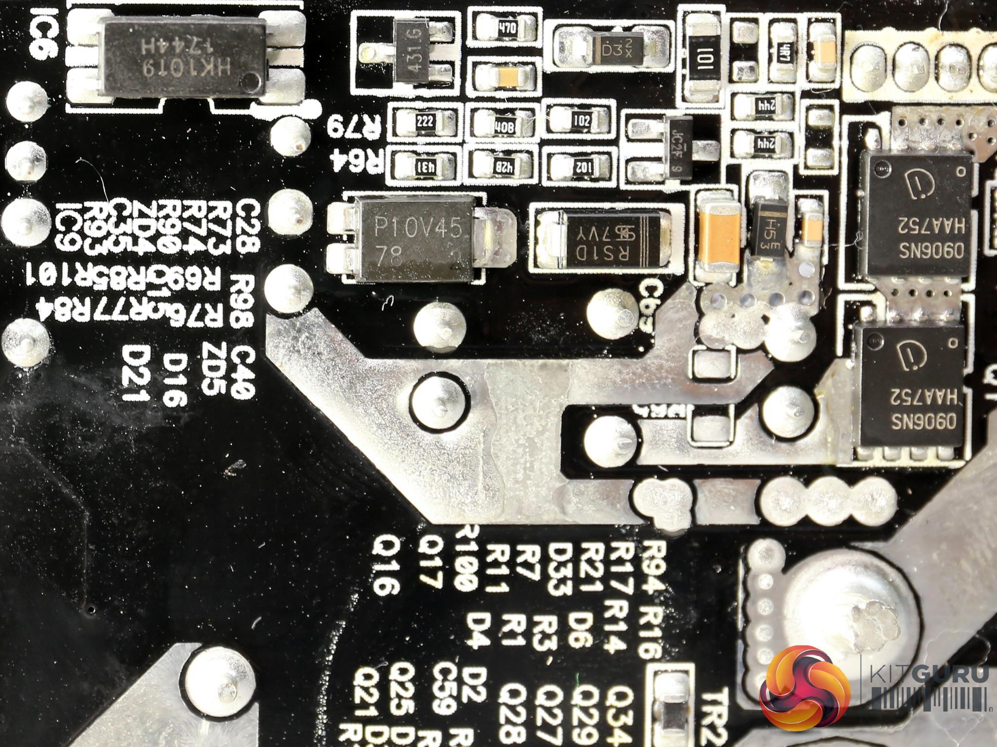
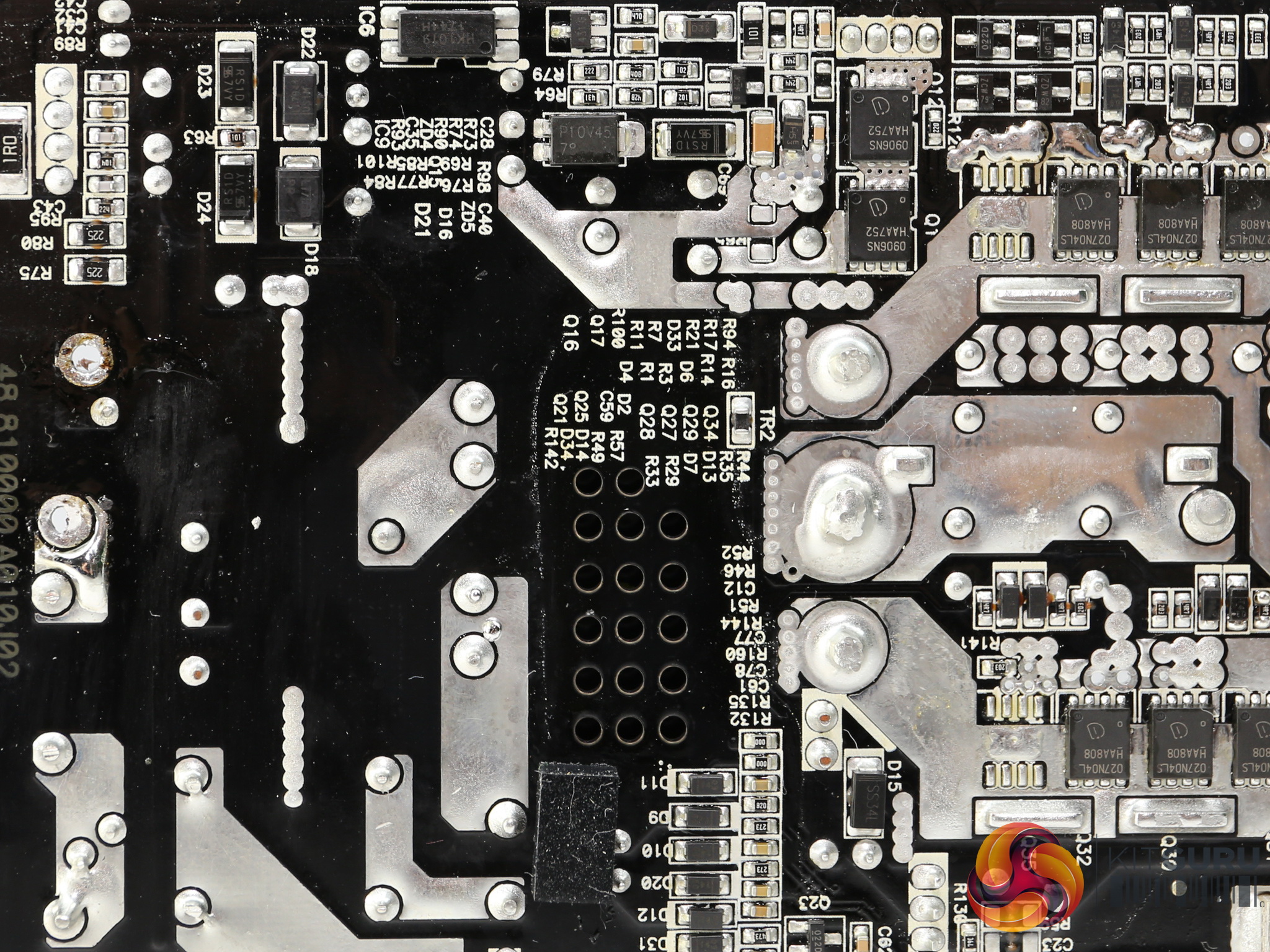
This is a High Power platform, featuring an extra circuit for the RGB controller and an EEPROM, which helps the unit “remember” the last RGB setting. The capacitors are of high quality and the fan features a hydro dynamic bearing, so it will last a long time.
The FETs used in the secondary side belong to Infineon so there is no doubt about their quality, however we cannot say the same for the FETs of the primary side which come from a Chinese manufacturer, which we haven't encountered so far. Only time will tell if those Chinese FETs are good enough to outlive the ten-year warranty.
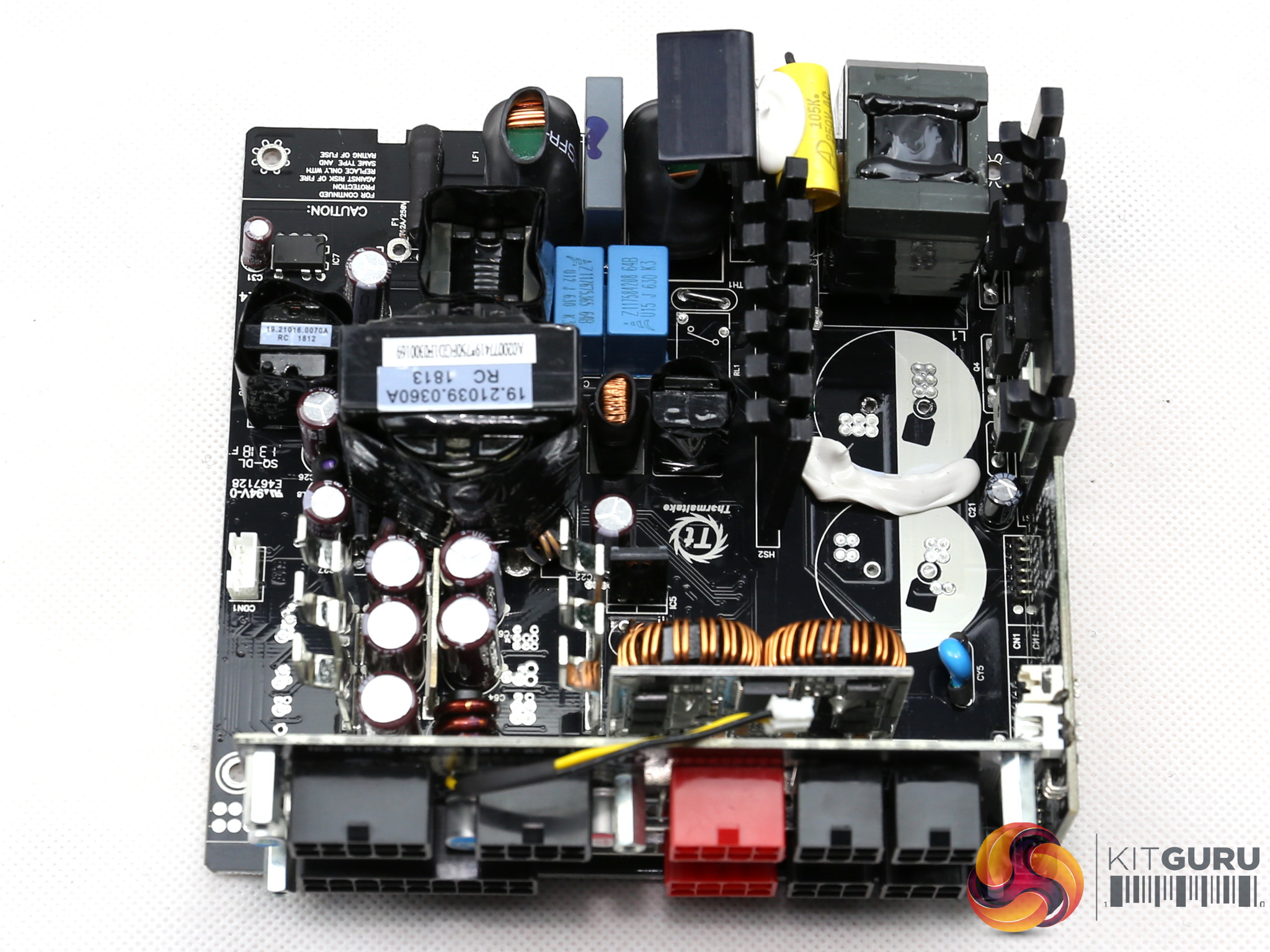

In the primary side we find the typical stuff such as a half-bridge topology along with an LLC resonant converter.
The secondary side uses a synchronous design where six FETs regulate the +12V rail. The minor rails are generated through a pair of DC-DC converters, which are fed by the +12V rail. It is always nice to see a dedicated regulation IC for the -12V rail, which provides enhanced security.
This rail can still harm the supply, so the sooner we get rid of it the better. The latest ATX specs don't list it as required, however all manufacturers still keep it in order to avoid any potential compatibility problems.
![]()
![]()
![]()
![]()
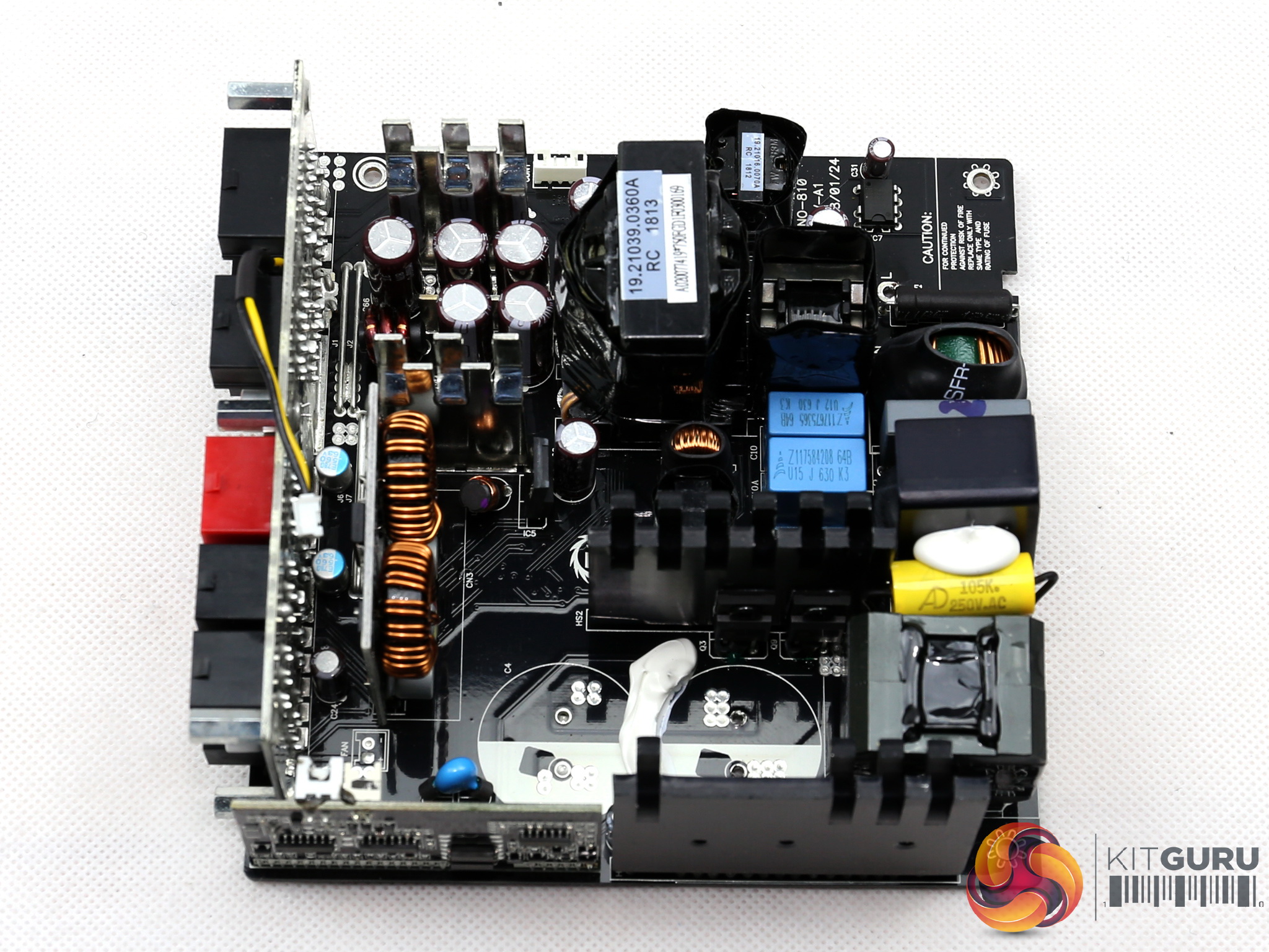
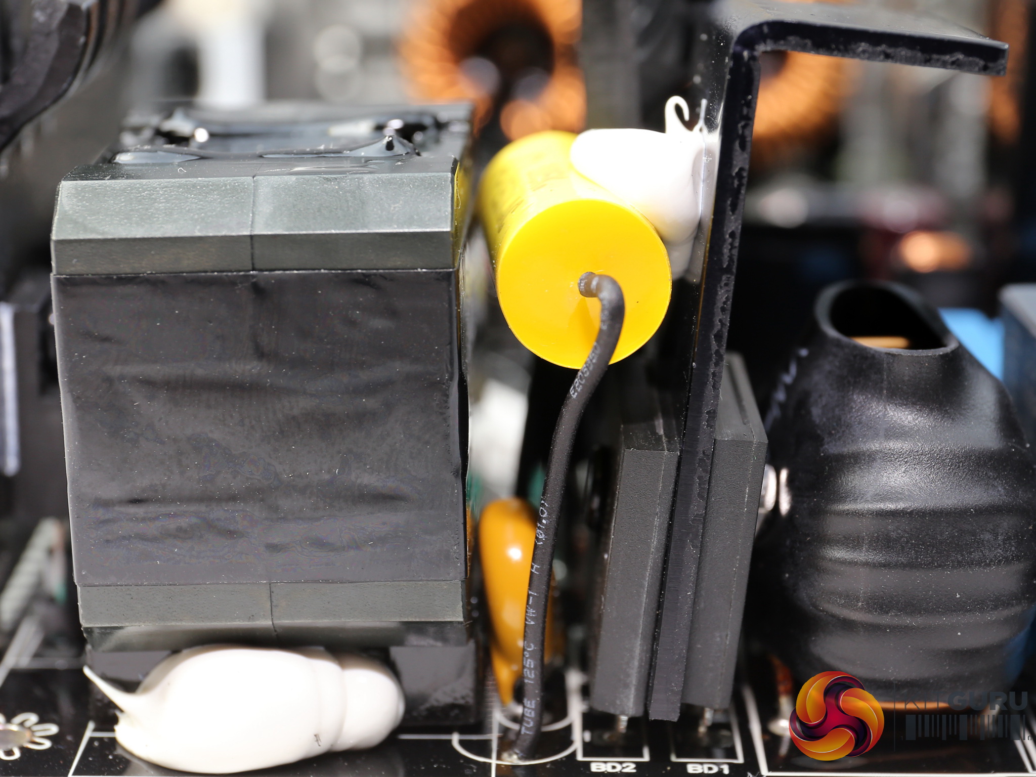
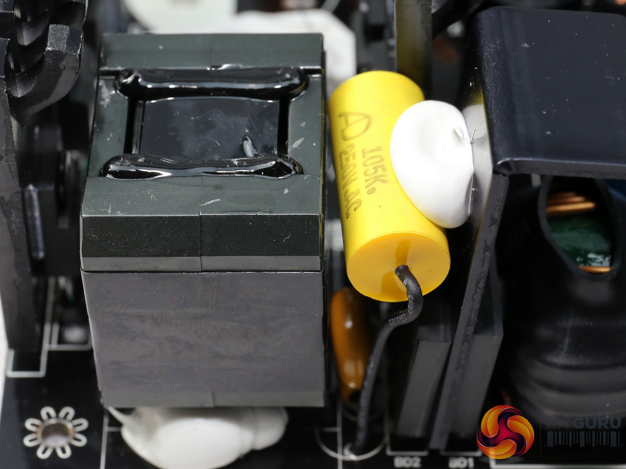
The EMI filter consists of two stages. The first is located at the AC receptacle and includes two Y and a single X caps. The second part, on the main PCB, has the same type and number of caps along with two CM chokes and an MOV, located after the bridge rectifiers.
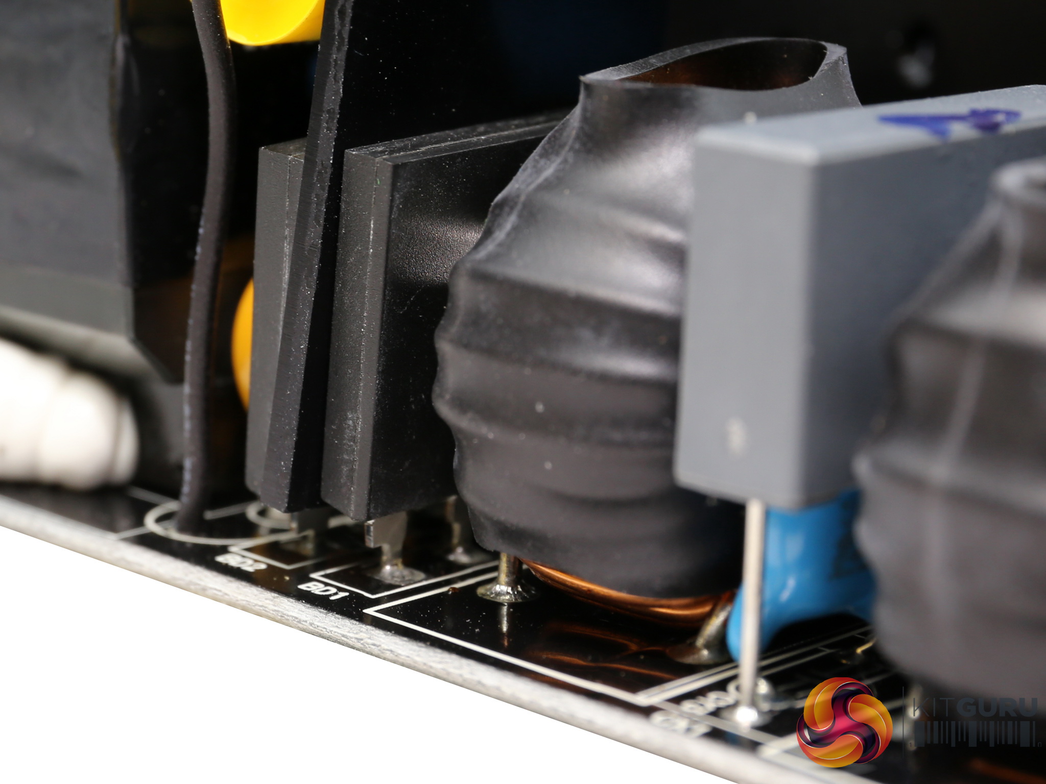
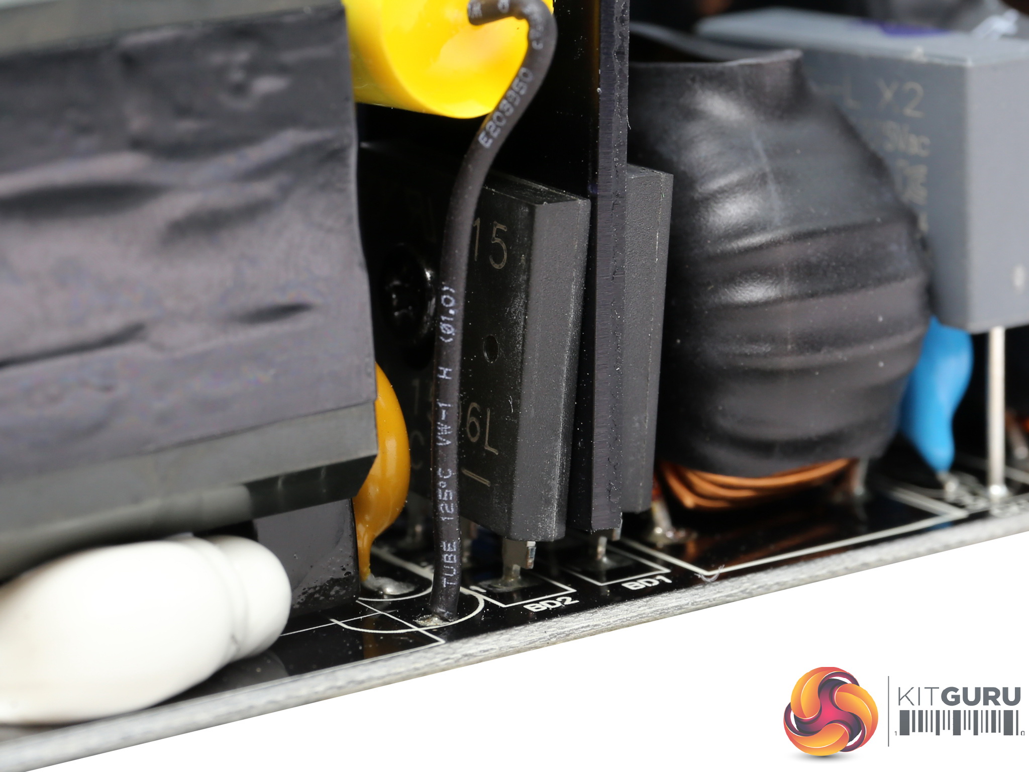
The pair of bridge rectifiers (GBU1506) can handle up to 30 Amps.
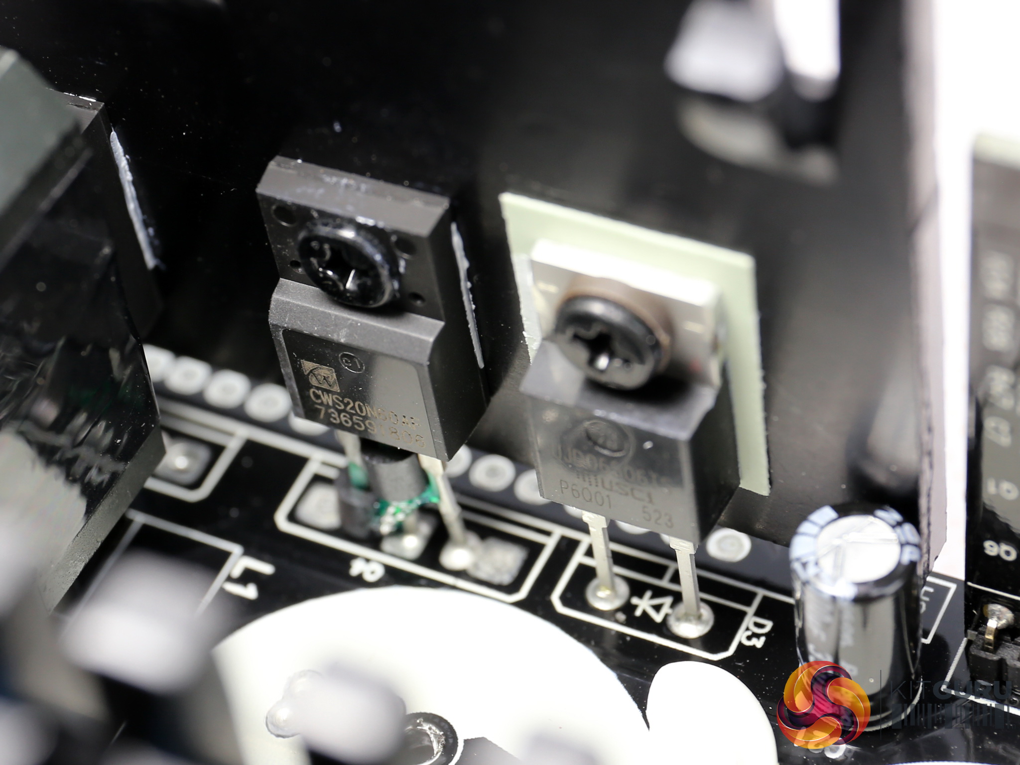
The APFC converter uses two China Wind CWS20N60AF FETs and a single UnitedSiC UJD06506TS boost diode. We would like to see Infineon FETs in this stage, instead of those unknown parts. The quality of the FETs used in the APFC converter and as primary switching FETs is of immense importance, since they have to deal with the mains grid and possible brown outs or voltage surges.
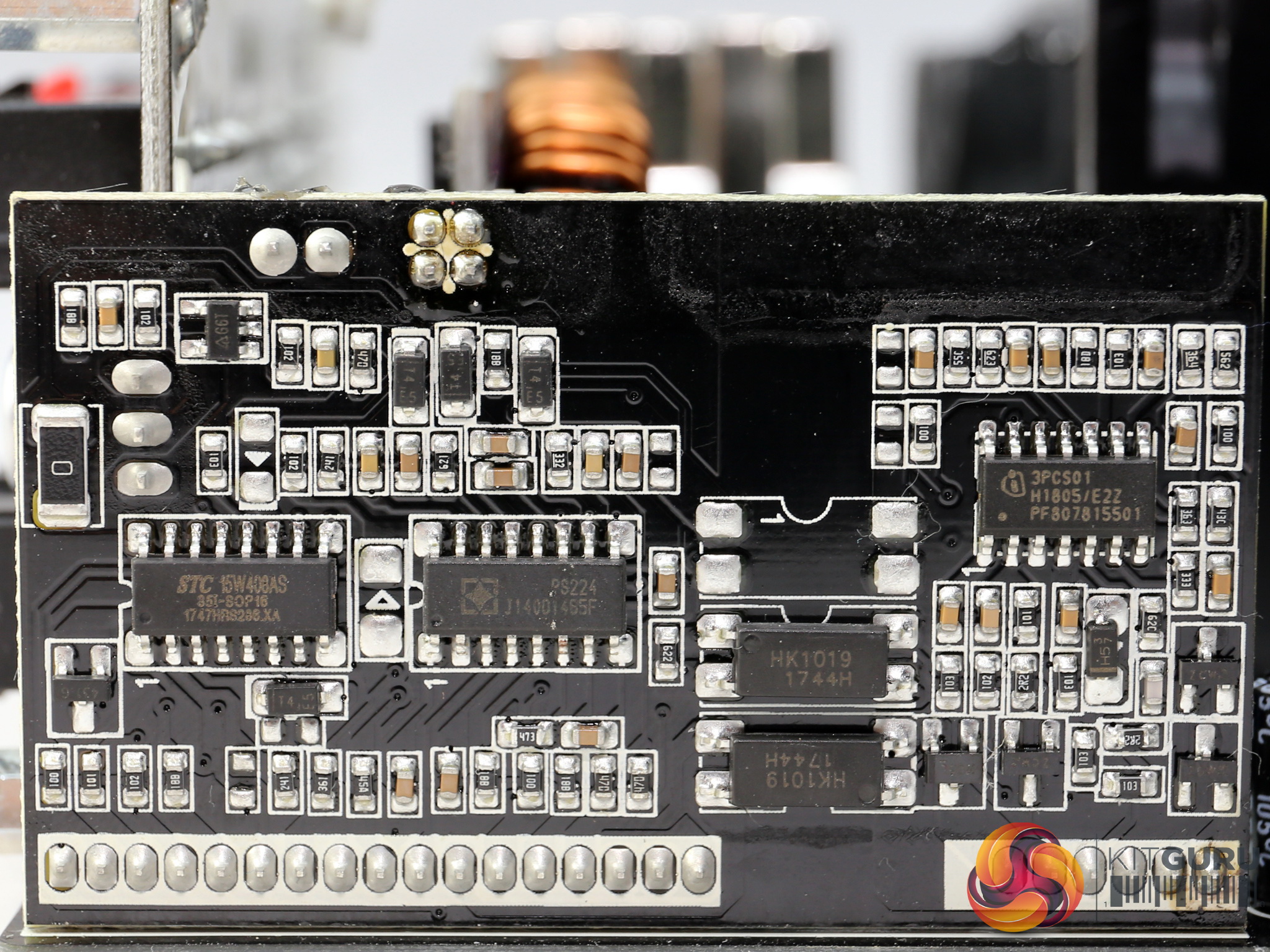
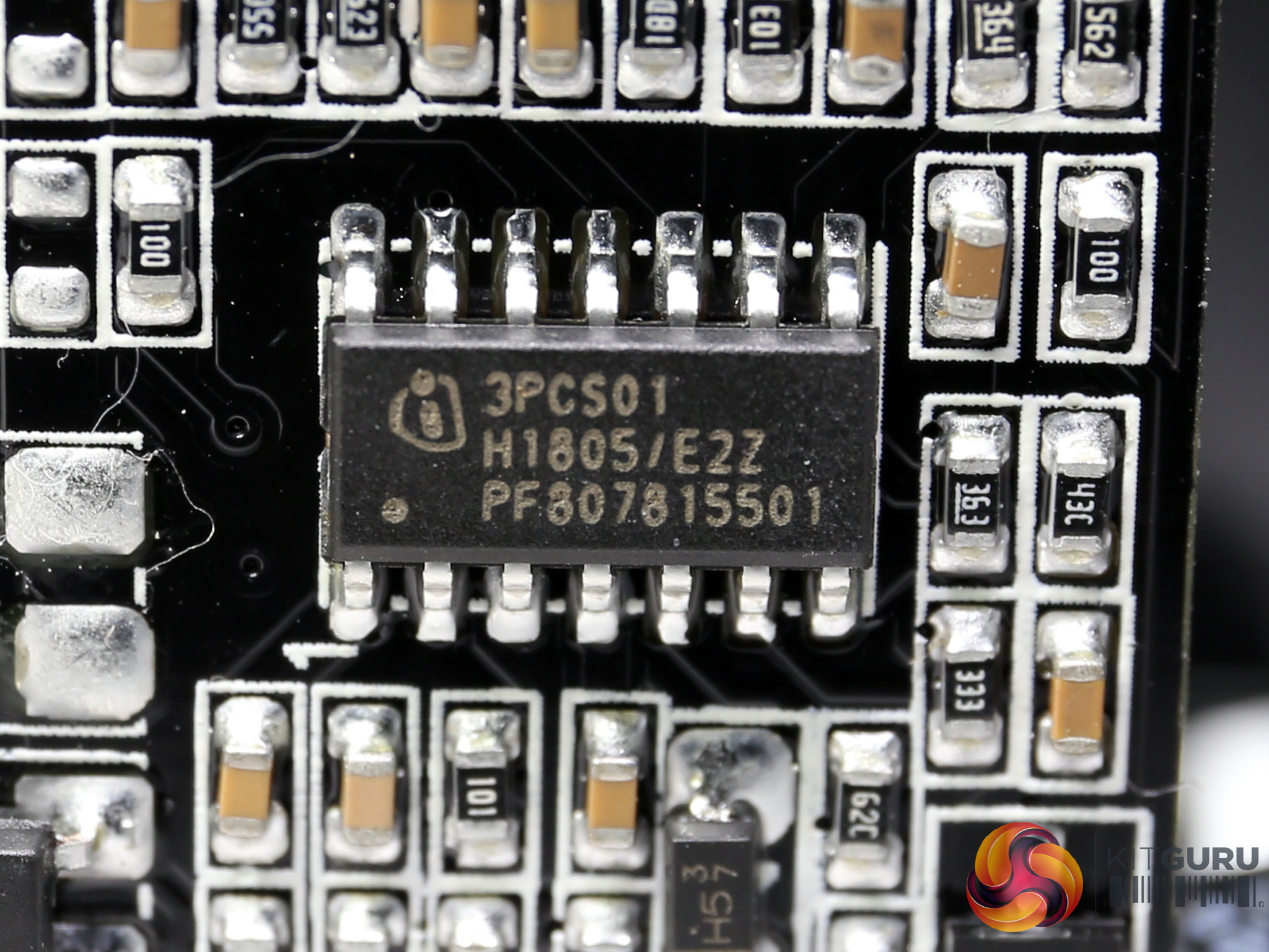
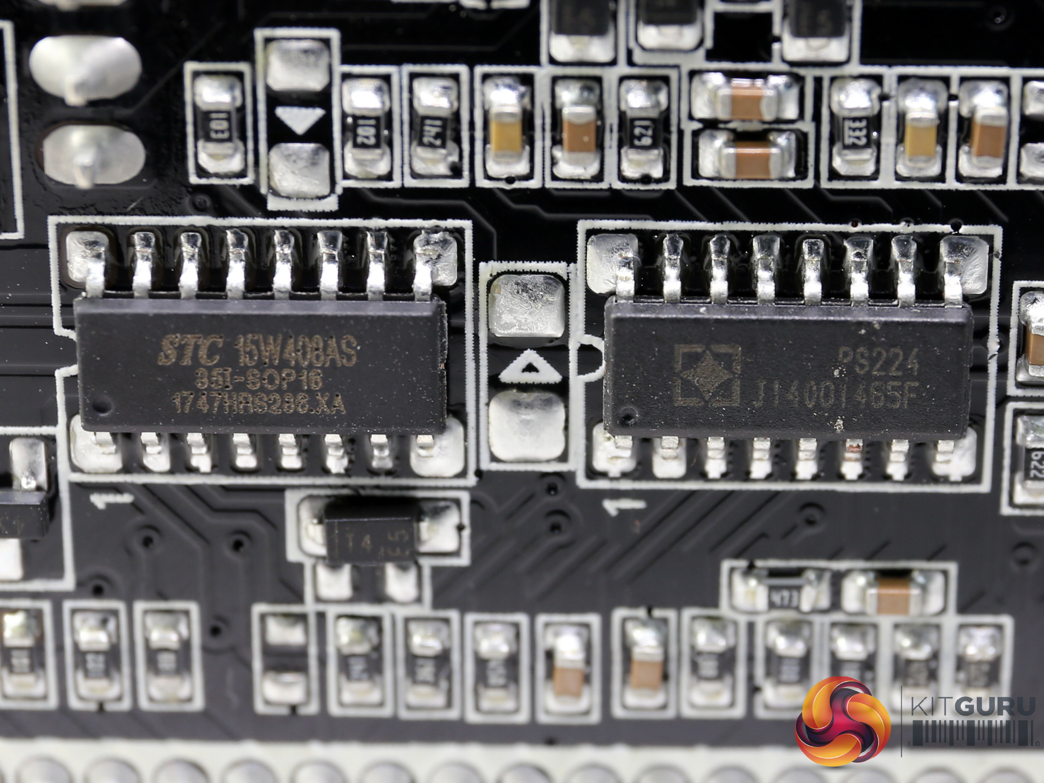
The APFC converter's controller (Infineon ICE3PCS01G) is installed on a large daughter-board, which also hosts the supervisor IC, a SITI PS224, and an MCU (STC15W408AS) which most likely plays a role in the fan control circuit.

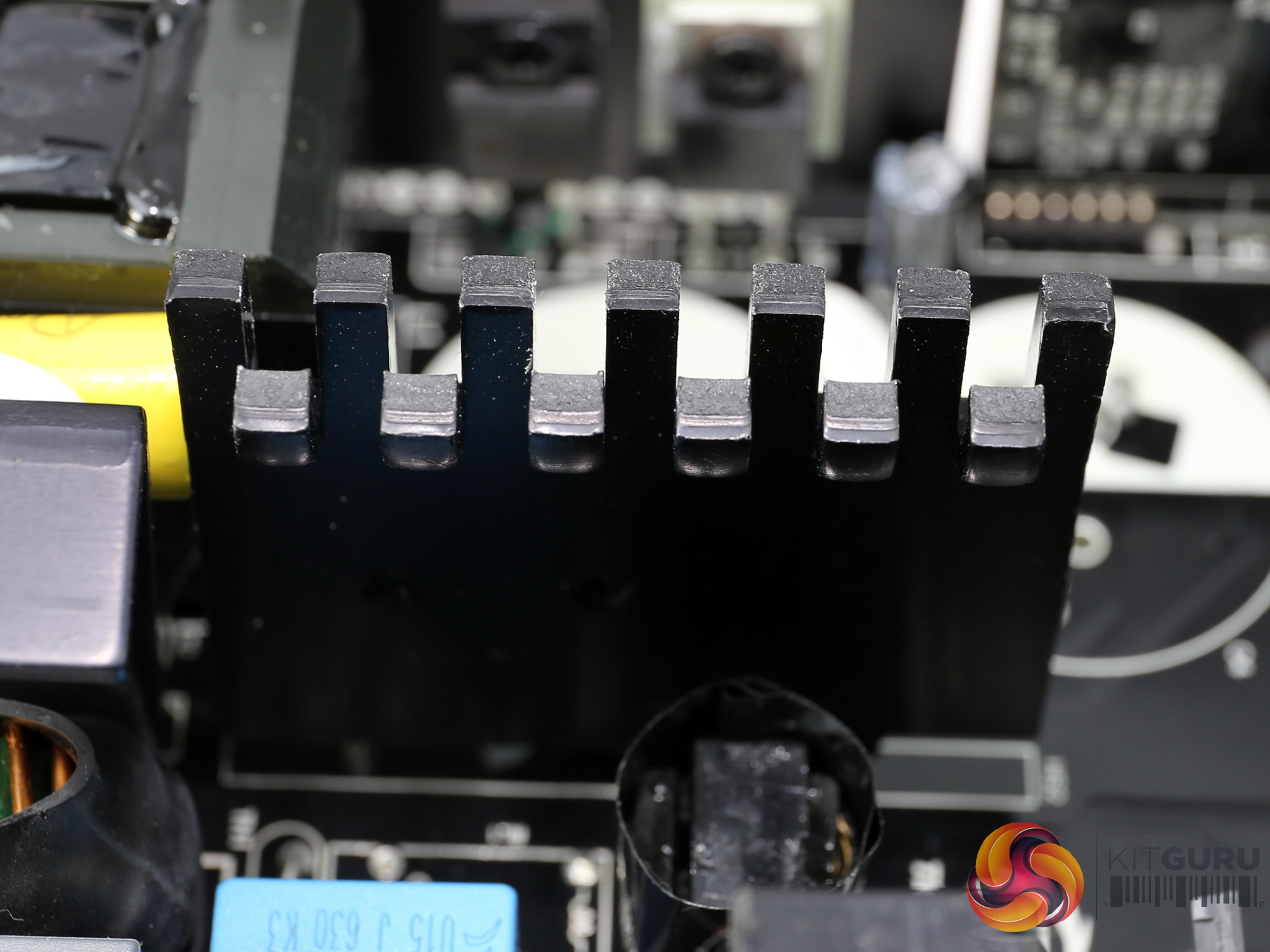
The primary switching FETs are two China Wind CWS20N60AF, the same with the ones used in the APFC converter. They are installed onto a small heatsink with tiny fins.
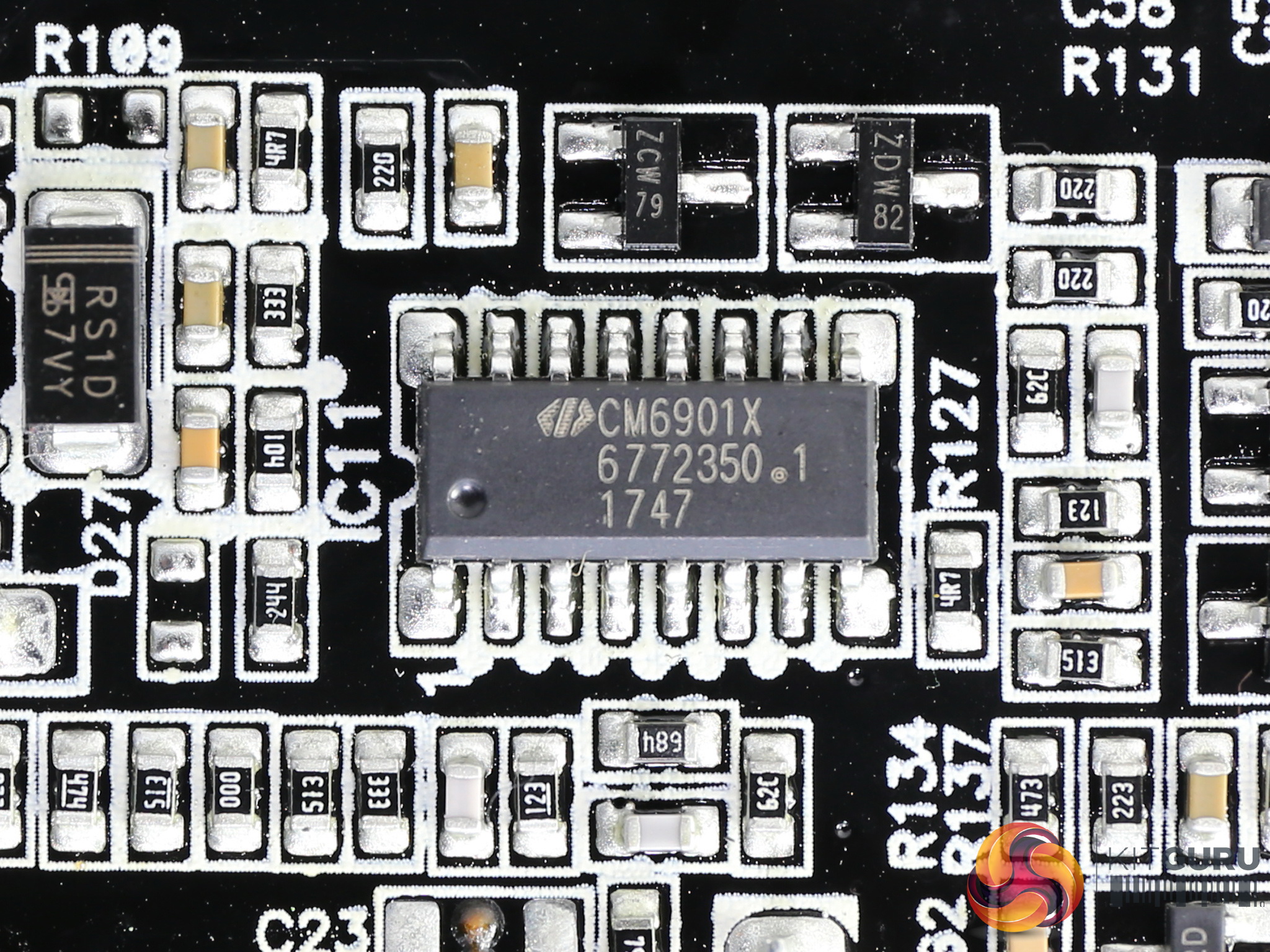
The LLC resonant converter is a Champion CM6901X which operates the primary FETs in PWM mode under light loads, while it switches to FM mode at higher loads. It is installed on the solder side of the main PCB.
![]()
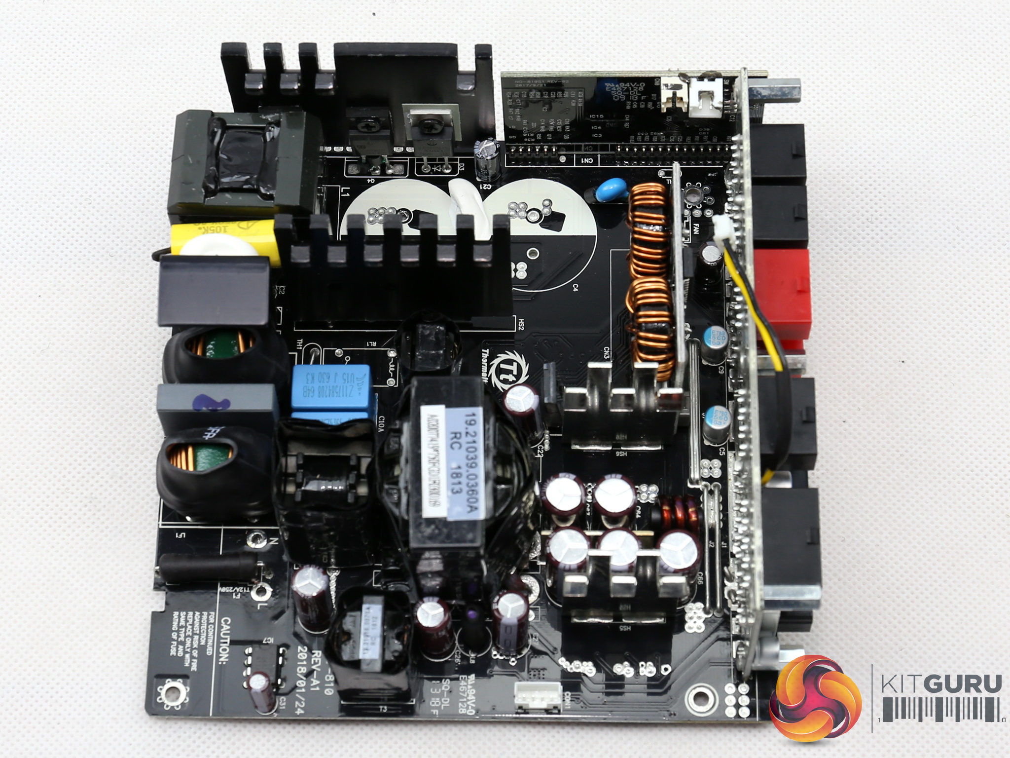
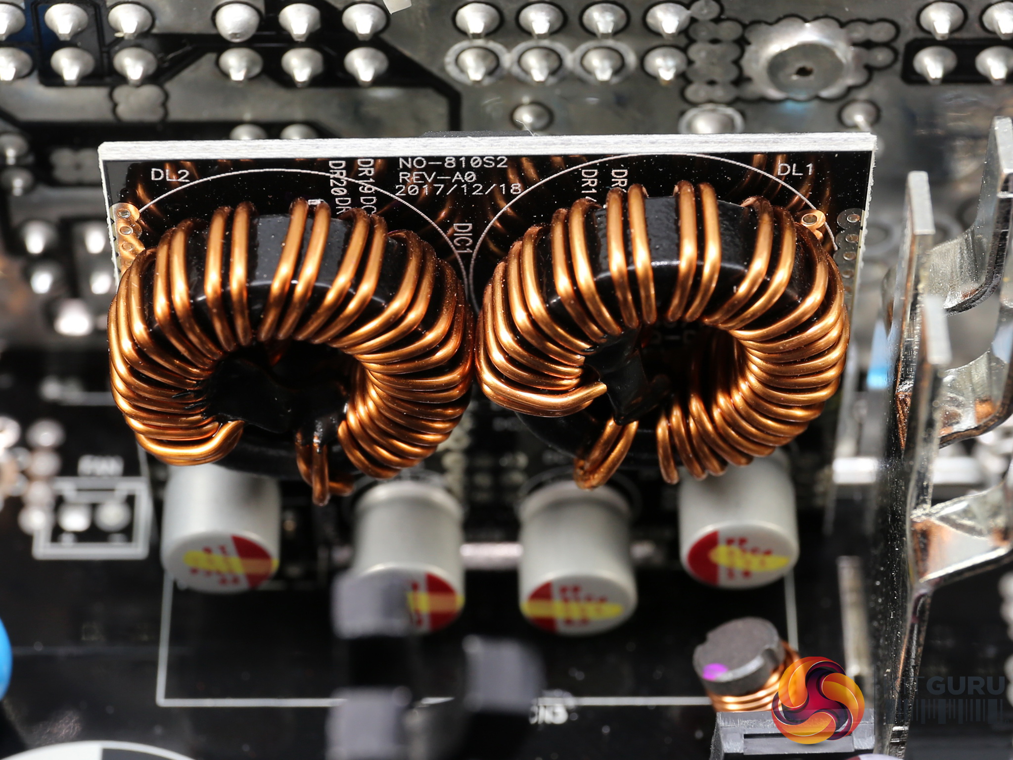
The main transformer besides lowering the voltage of the primary side, also provides electrical isolation.
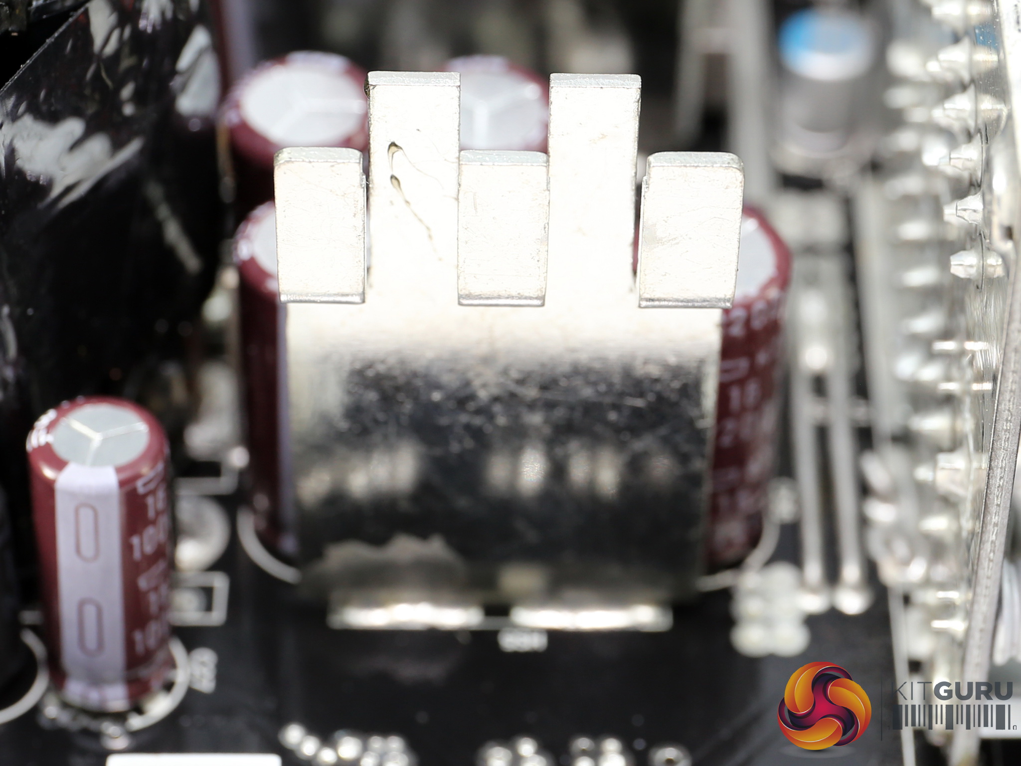
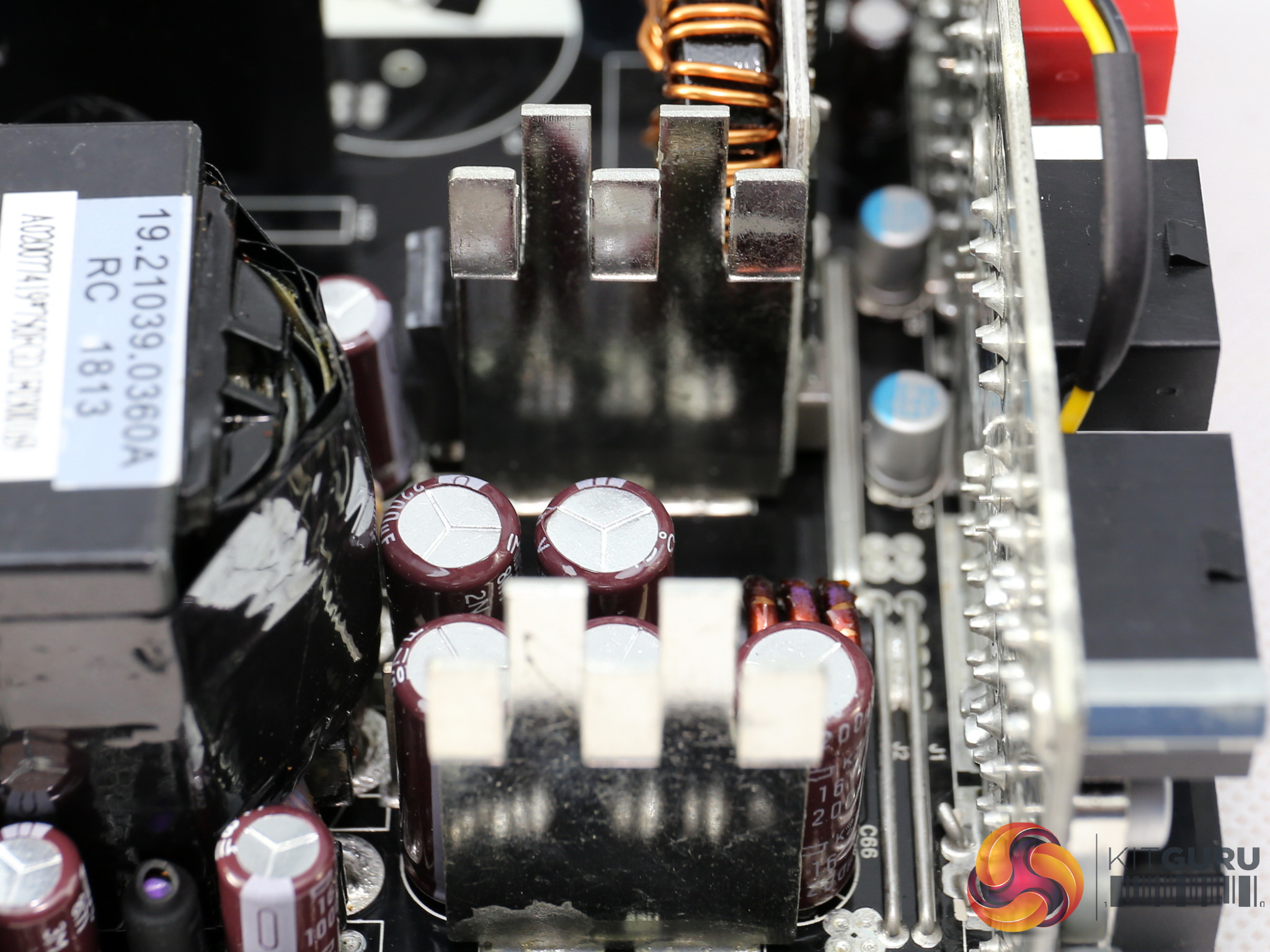
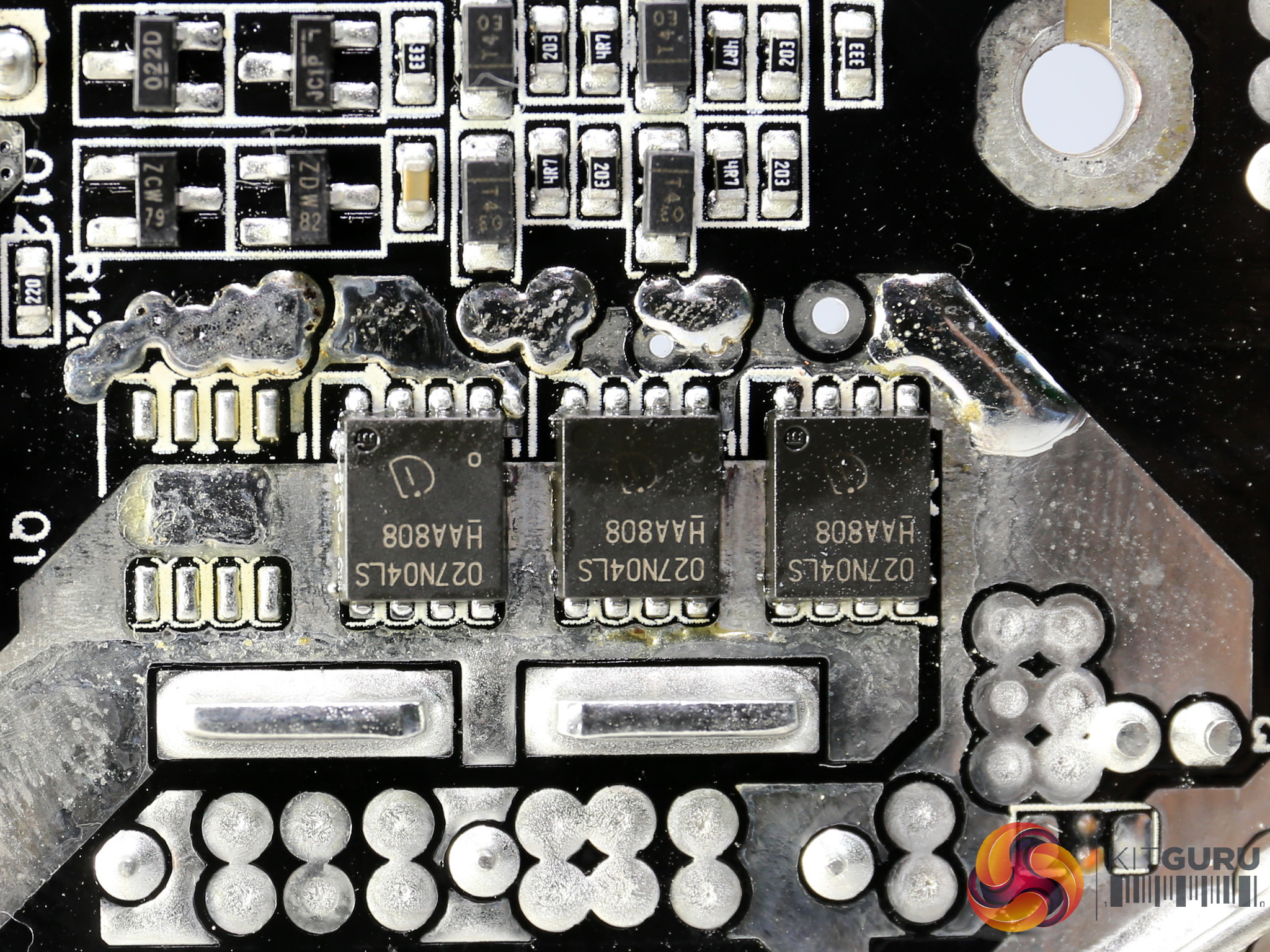
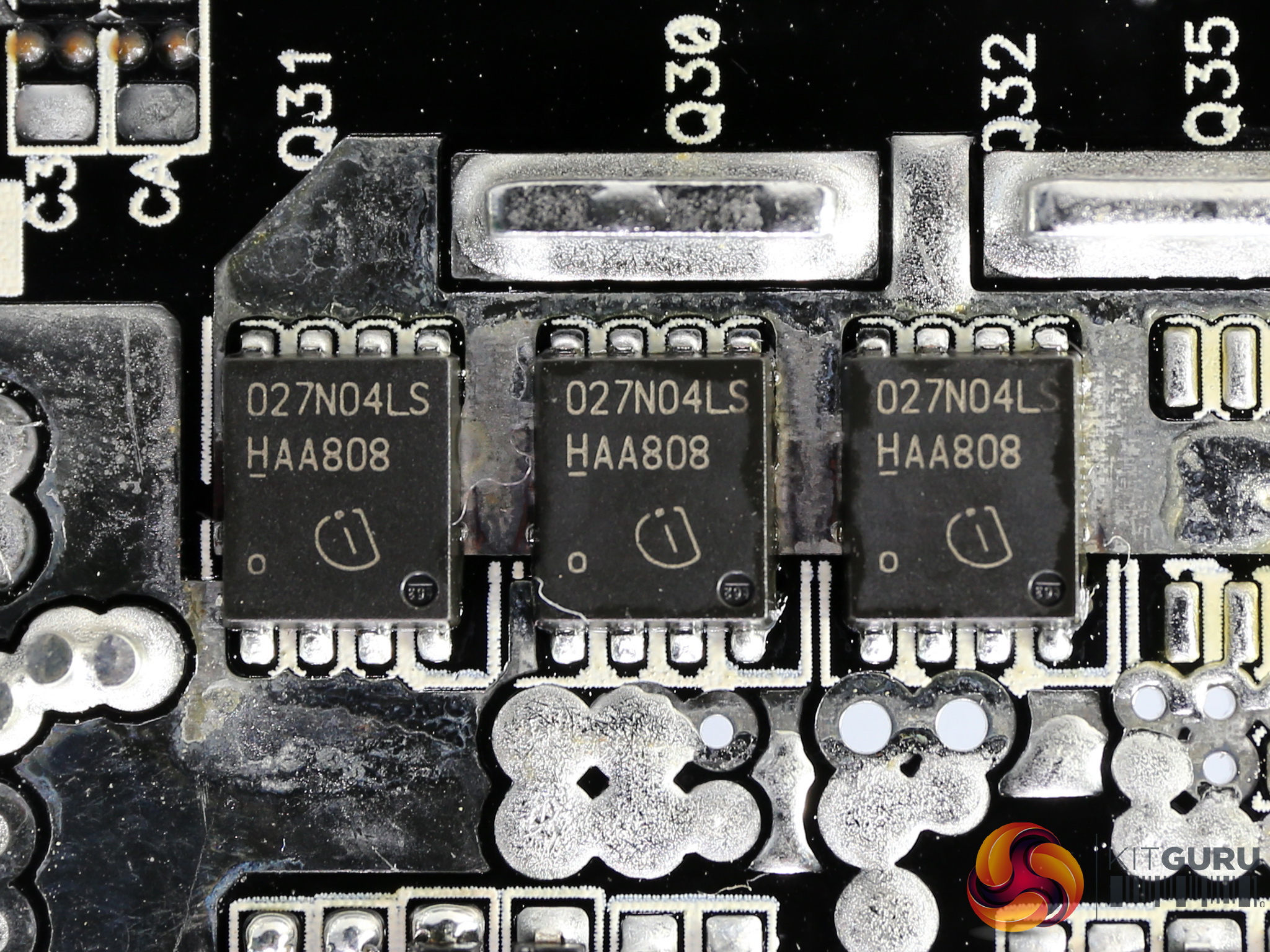
The couple of small heatsinks in the secondary side is used to dissipate the heat that the +12V FETs generate, with the latter installed on the PCB's rear side. In total six Infineon BSC027N04LS G handle the +12V rail.
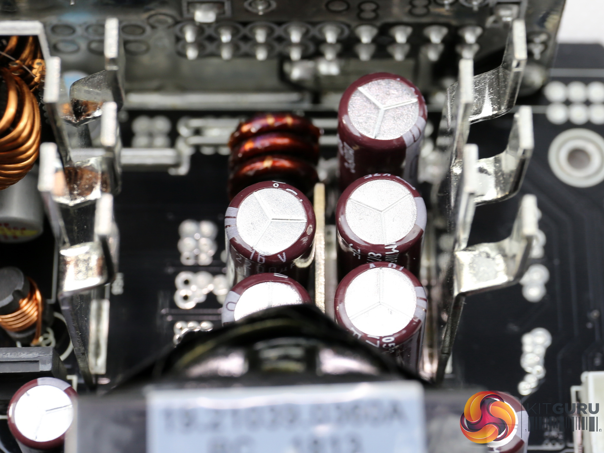
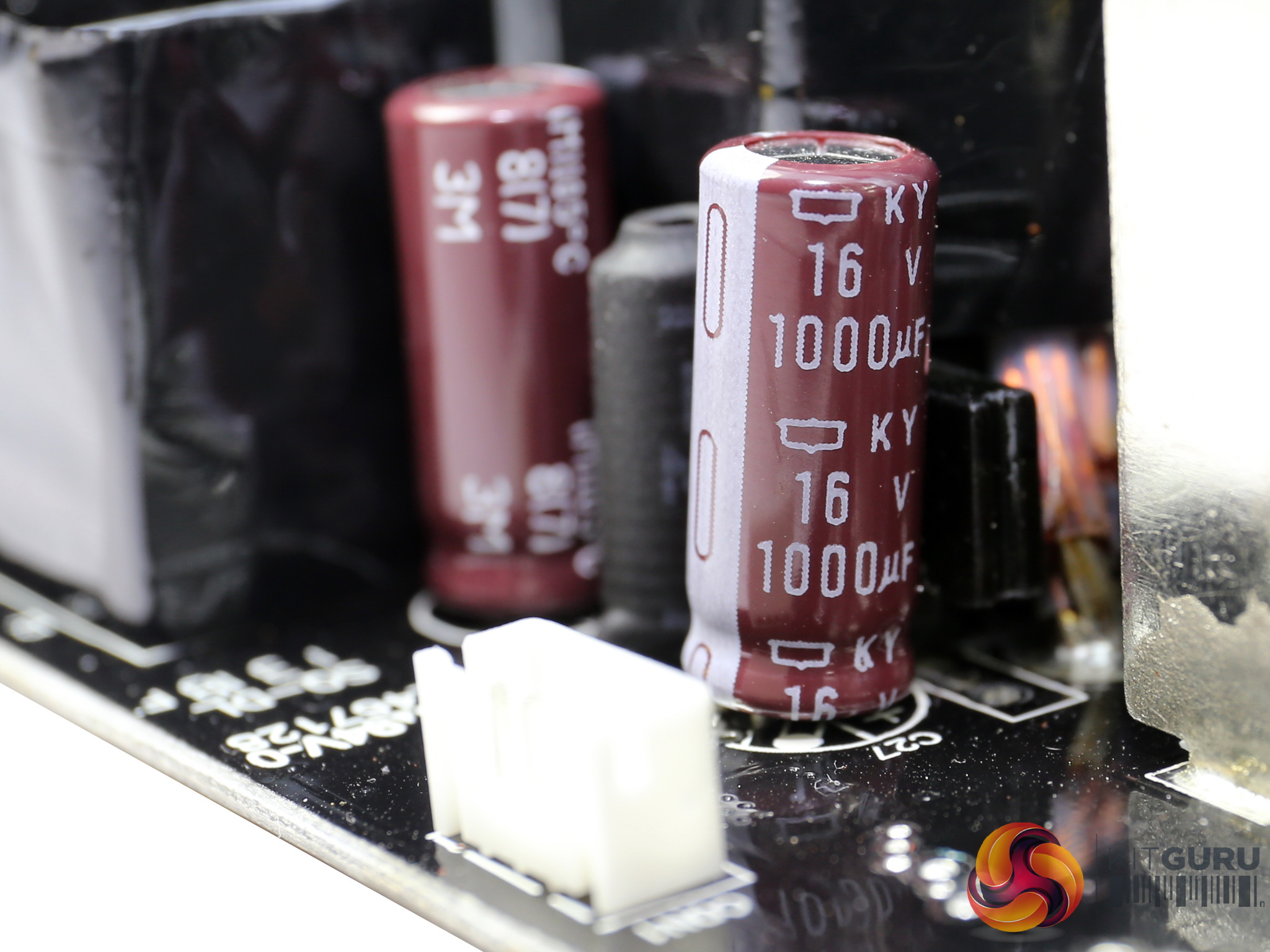
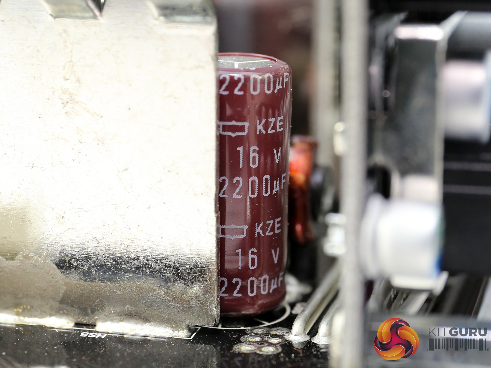
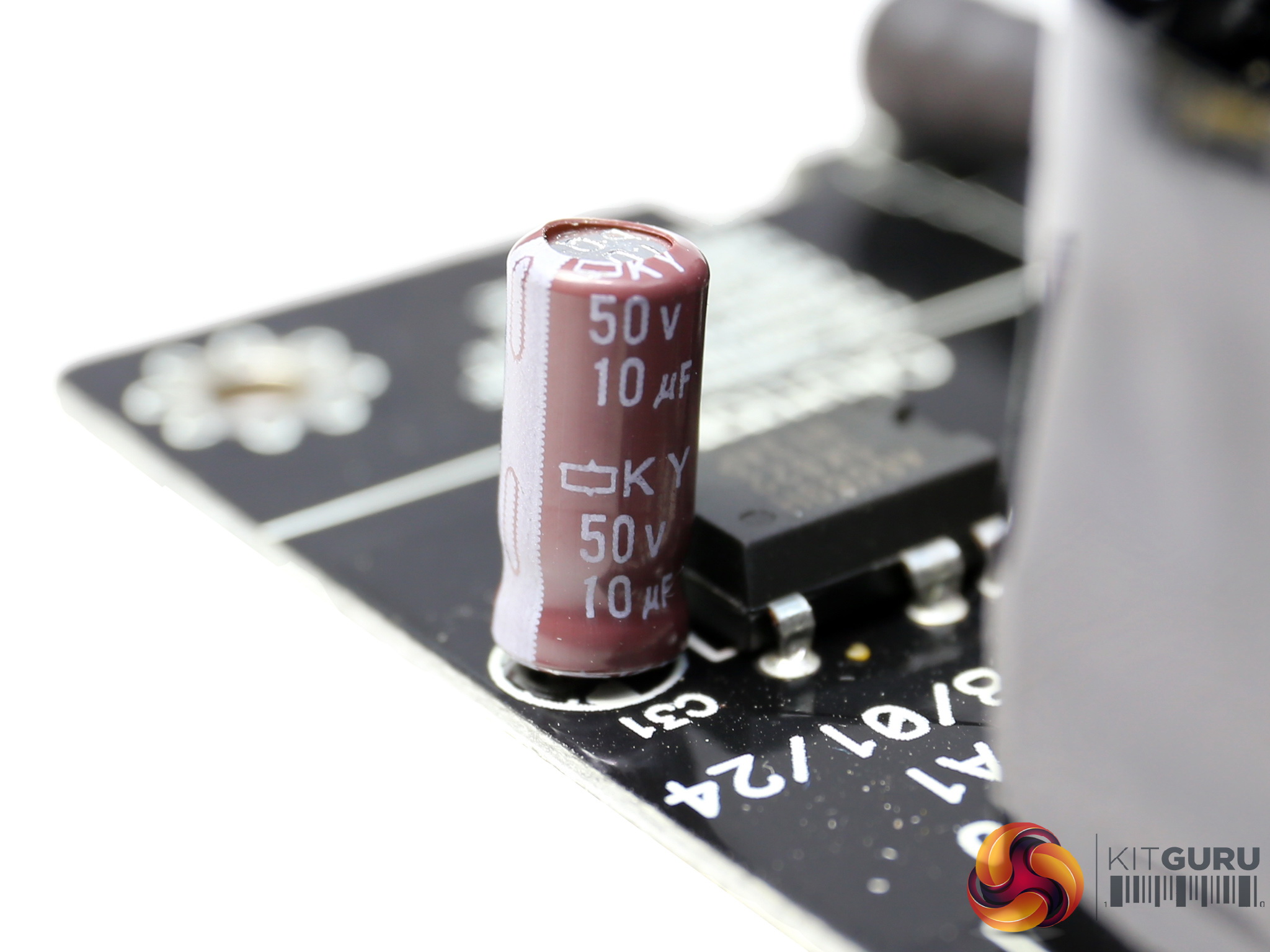
The electrolytic filtering caps in the secondary side are provided by Chemi-Con and belong to its KY and KZE lines.
We also find a lonely Rubycon (ZLH series) of small capacity. Besides electrolytic caps a small number of Chemi-Con and FPCAP polymers caps is also used, with the majority of them installed on the modular board.
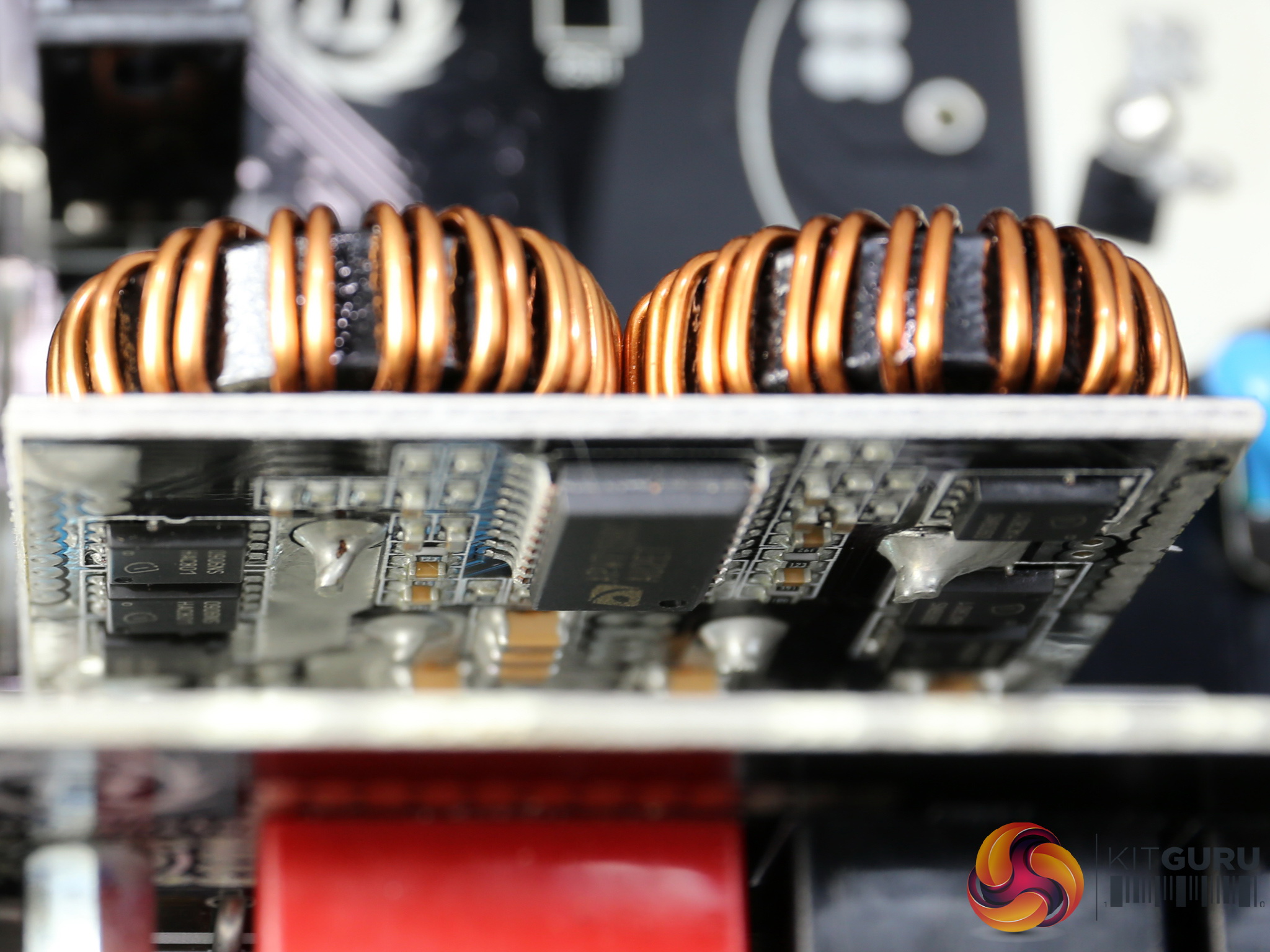
A pair of DC-DC converter uses six Infineon BSC0906NS FETs. The common PWM controller is a Anpec APW7159C.
![]()
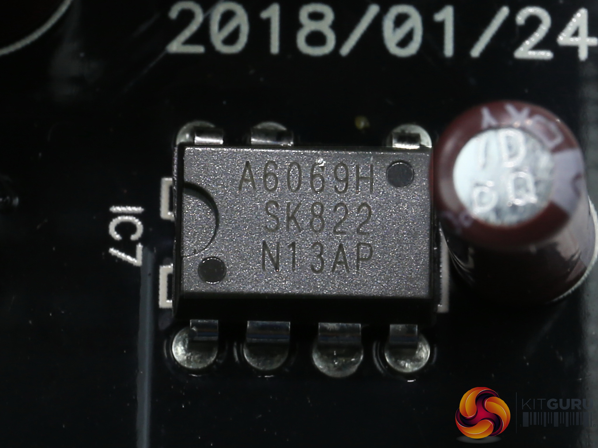
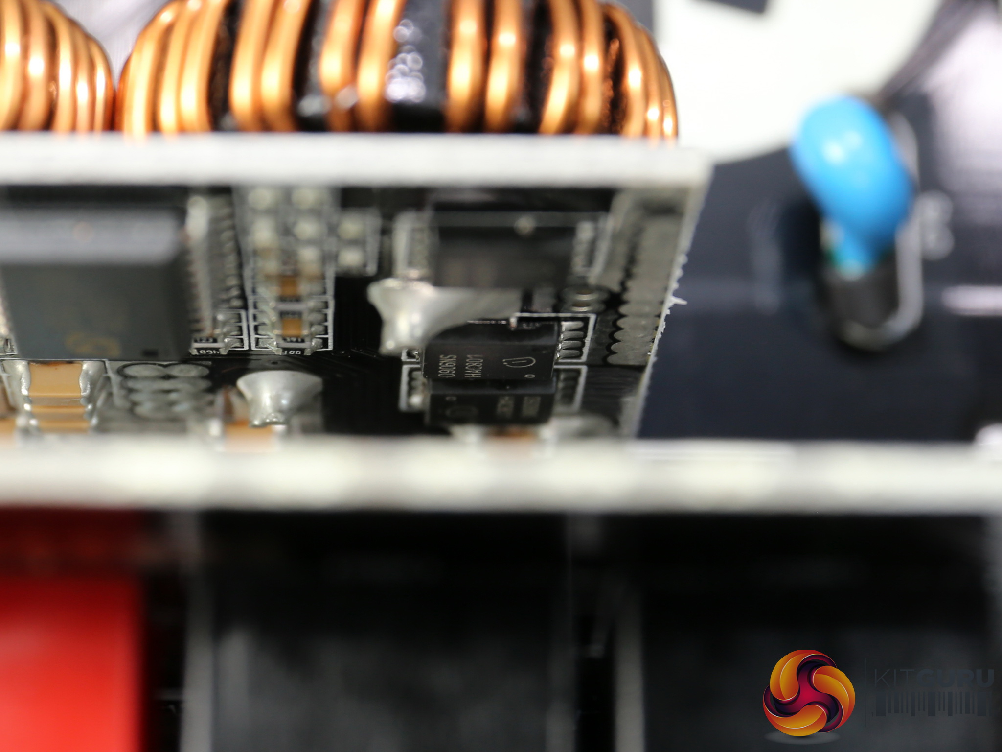
The 5VSB circuit besides a small transformer also utilizes a PCF P10V45 SBR. We spotted two Infineon BSC0906NS FET on the main board, which look to belong to this circuit as well. Finally, the standby PWM controller is a Sanken STR-A6069H.
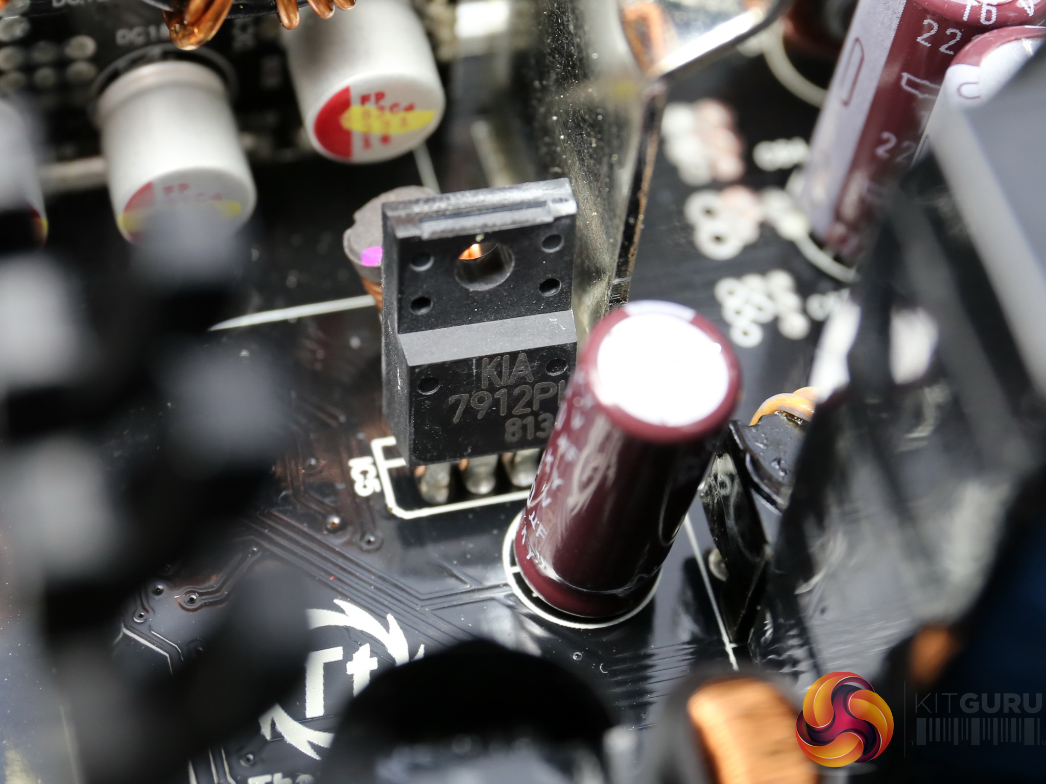
The -12V rail instead of a plain diode uses a proper regulation IC, a KEC KIA7912PI.
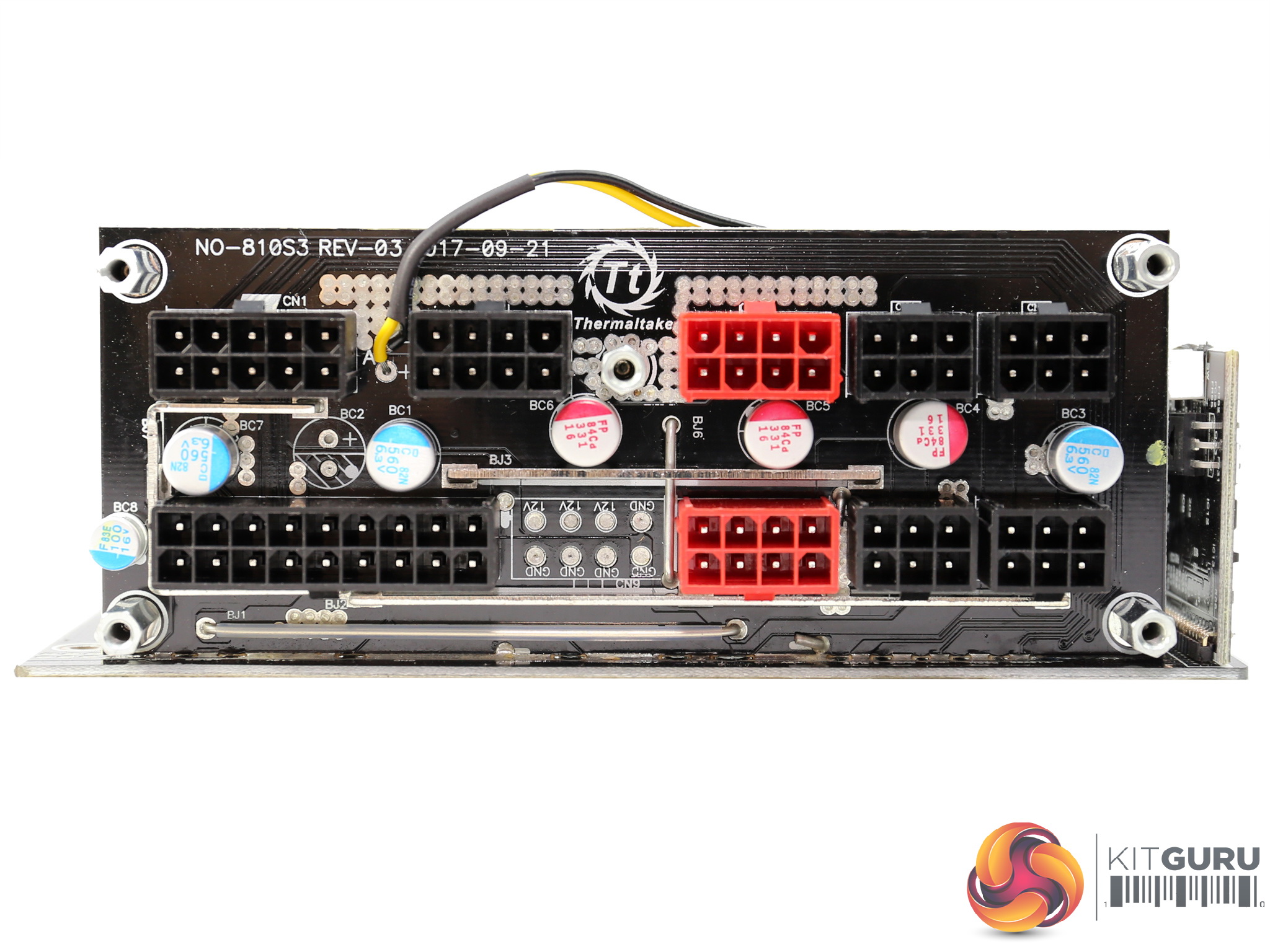

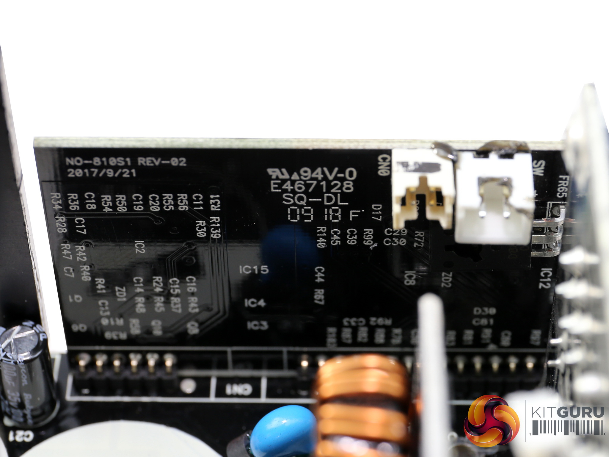
The modular board hosts four Chemi-Con and three FPCAP polymer caps. As you can see there was room for an additional 8-pin connector and it is a real shame that High Power didn't utilize it, since this unit should have a second EPS socket.
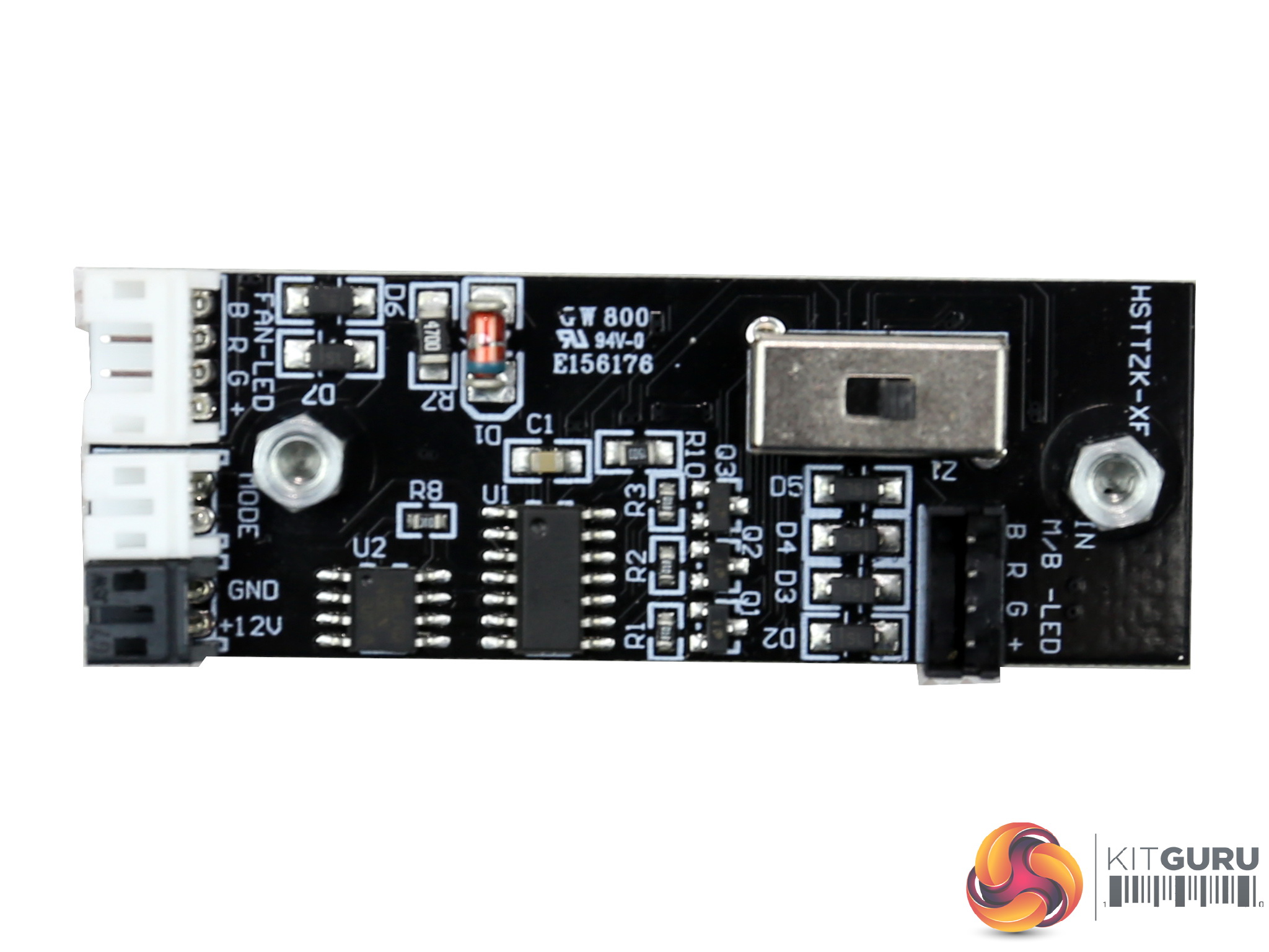
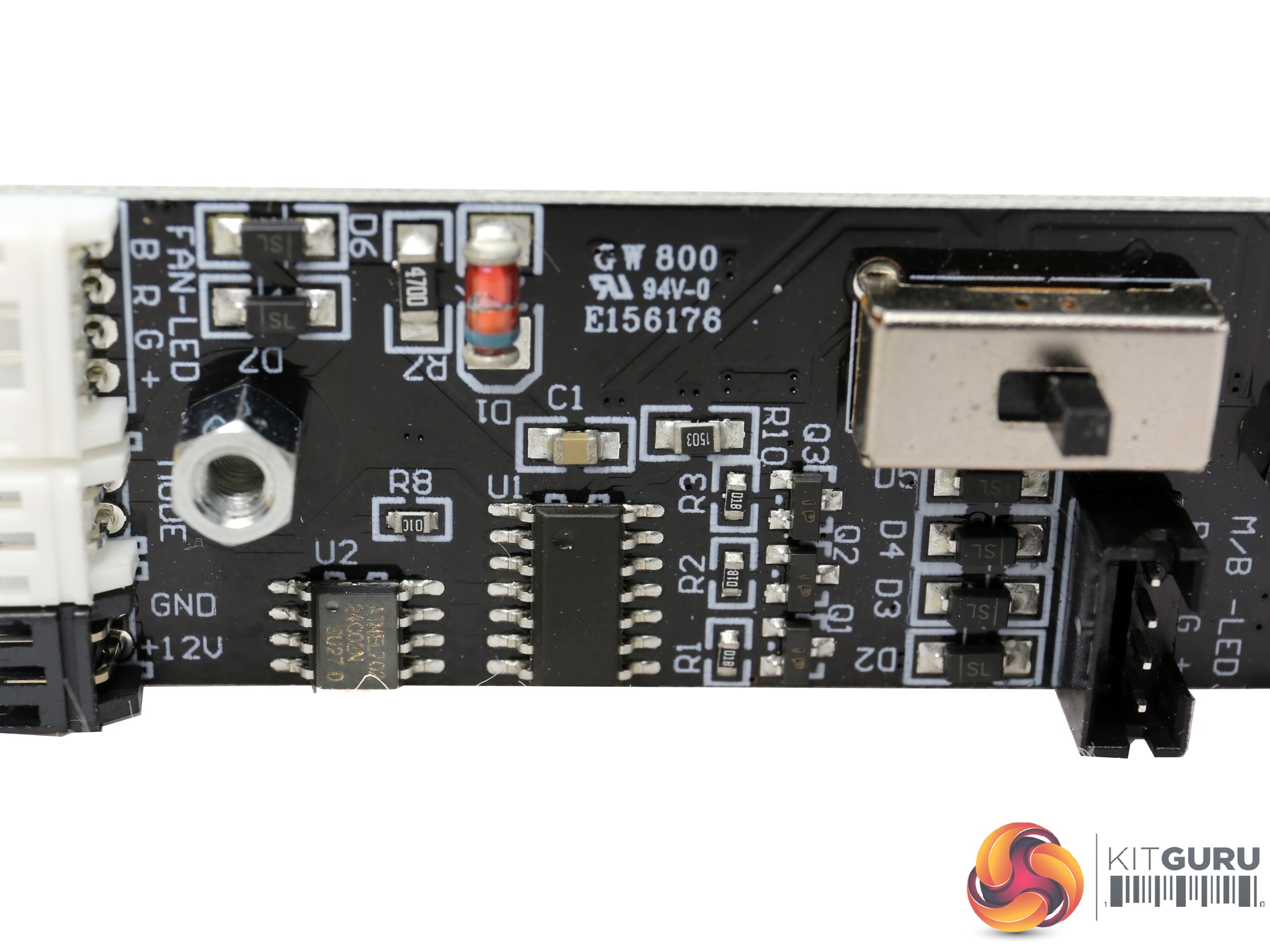
The RGB control IC and the serial EEPROM (ATMEL AT24C02N) are installed onto this small PCB. The marking on the control IC were totally erased, so we cannot identify its model number.
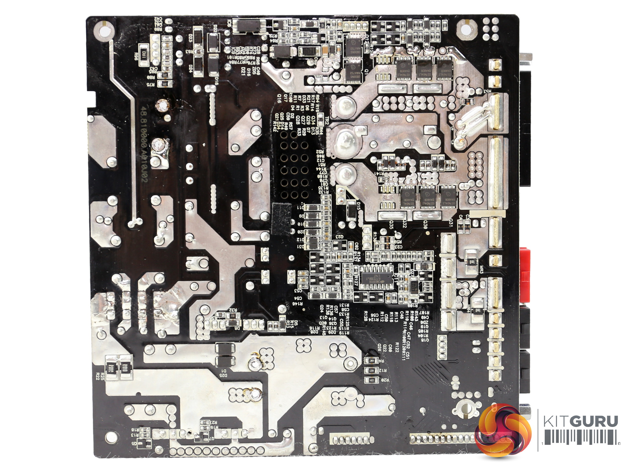
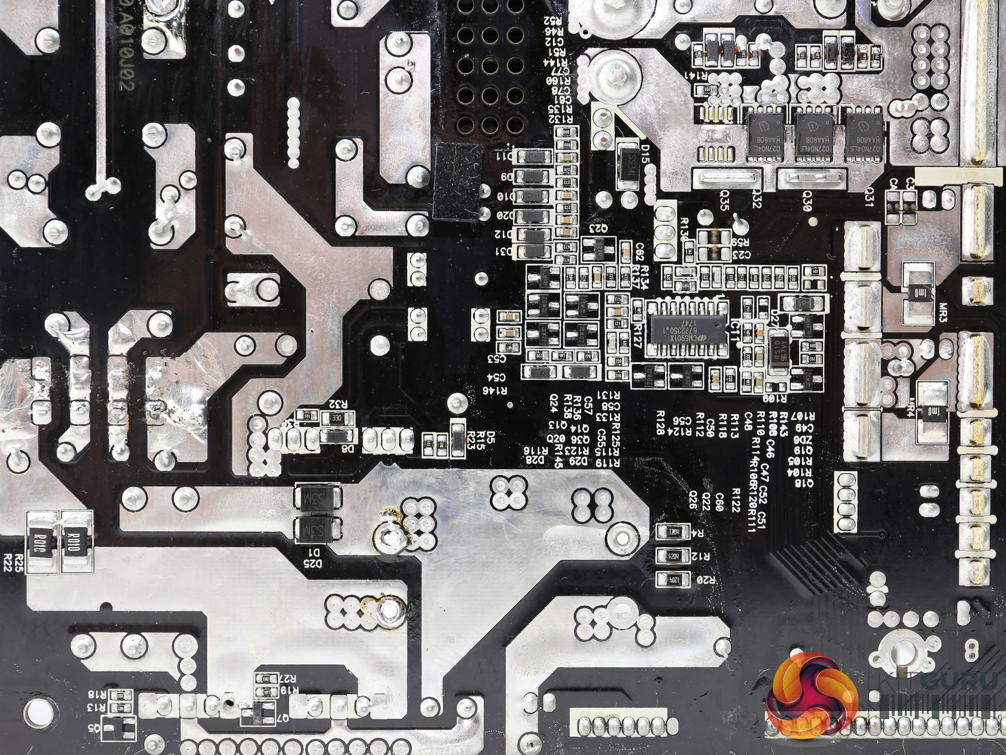
The soldering quality is not the best we have seen from High Power, that's for sure, but it is still pretty good. What gave us a really hard time though was the desoldering of some parts since the lead-free solder is very tough to work with – it demands very high temperatures in order to melt.
We are aware that the regulations ask for lead-free parts, but in the end this hard-to-work-with solder type brings more trouble than the one containing lead.

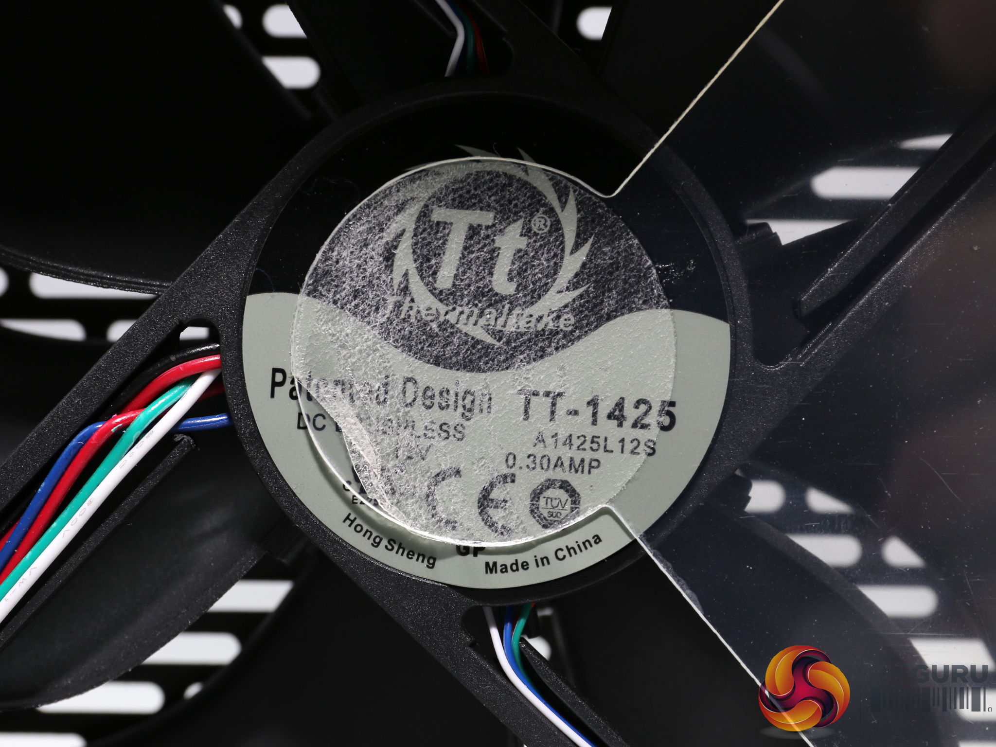
The cooling fan has Thermaltake's name on it and its model number is TT-1425. Its original manufacturer is Hong Sheng and the initial model number, before TT's relabeling, is A1425L12S. This is a low speed fan with a hydro dynamic bearing, which offers a long lifetime.
To learn more about our PSU tests and methodology, please check out How We Test Power Supply Units.
Primary Rails And 5VSB Load Regulation
Load Regulation testing is detailed here.

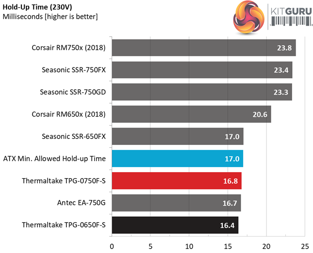
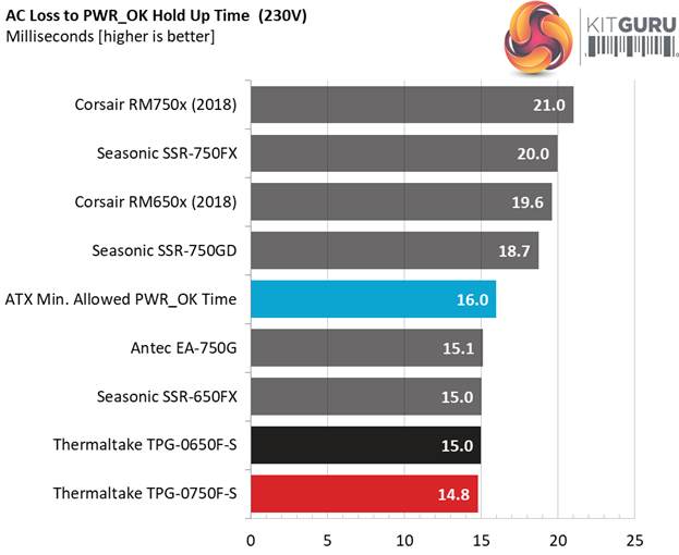
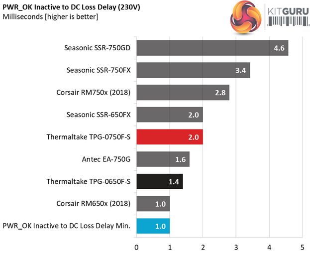
Hold-Up Time
Our hold-up time tests are described in detail here.
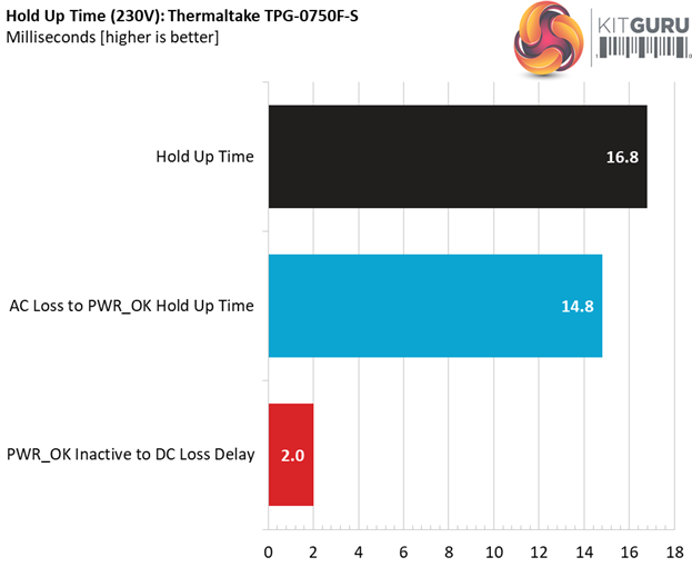
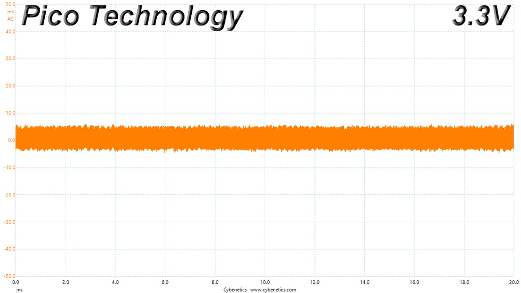
The oscilloscope screenshots that we took during the hold-up time measurements:
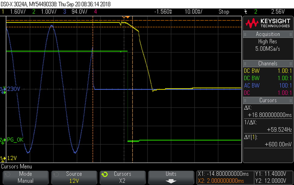

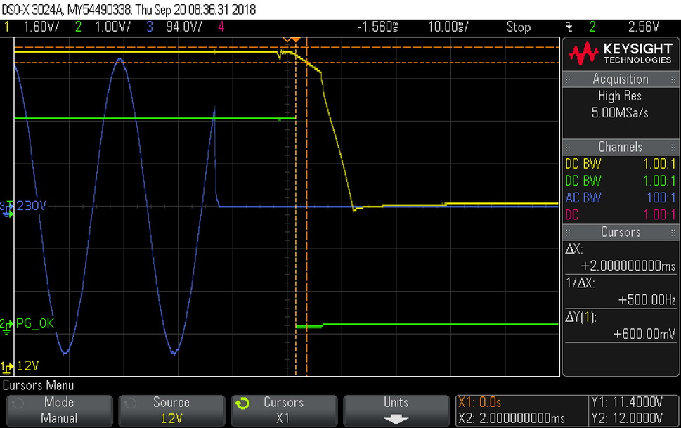
The hold-up is very close to 17ms, with the power ok signal needing 1.2ms to reach 16ms, which is what the ATX spec requires. At least it is accurate (the power ok signal).
Inrush Current
For details on our inrush current testing, please click here.
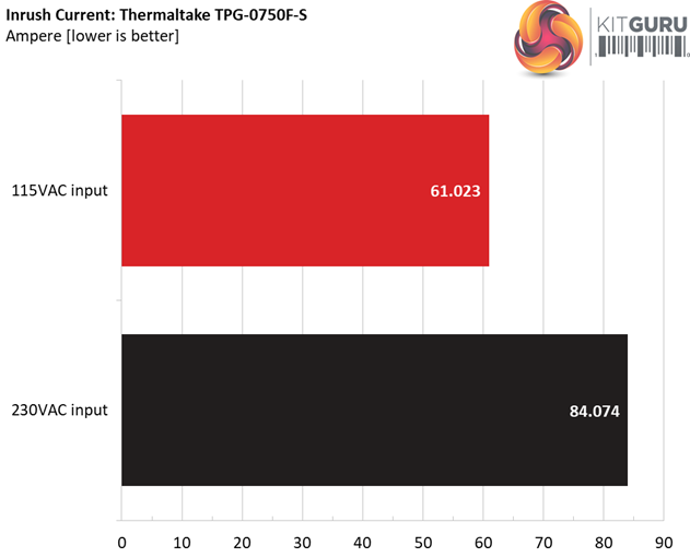
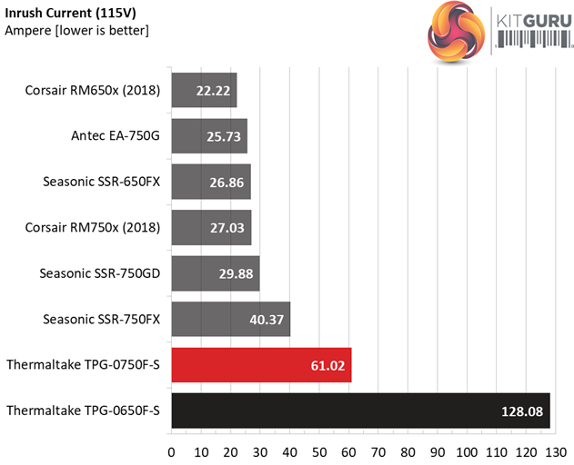
We measure high inrush current with both voltage inputs. What make us wonder here is the sky high inrush reading of the 650W model.
Load Regulation And Efficiency Measurements
The first set of tests reveals the stability of the voltage rails and the TPG-750AH3FSGR’s efficiency. The applied load equals (approximately) 10 to 110 percent of the power supplies maximum load in increments of 10 percentage points.
We conducted two additional tests.
During the first, we stressed the two minor rails (5V and 3.3V) with a high load, while the load at +12V was only 0.1A. This test reveals whether a power supply is compatible with Intel’s C6/C7 sleep states or not. In the second test, we determined the maximum load the +12V rail could handle with minimal load on the minor rails.
| Test # | 12V | 5V | 3.3V | 5VSB | DC/AC (Watts) | Efficiency | Fan Speed (RPM) | PSU Noise (dB[A]) | Temps (In/Out) | PF/AC Volts |
| 1 | 4.371A | 1.982A | 1.957A | 0.999A | 74.578 | 86.843% | 0 | <6.0 | 47.85°C | 0.947 |
| 12.118V | 5.051V | 3.372V | 5.005V | 85.877 | 40.37°C | 115.06V | ||||
| 2 | 9.798A | 2.979A | 2.950A | 1.204A | 149.460 | 90.367% | 0 | <6.0 | 48.87°C | 0.977 |
| 12.099V | 5.038V | 3.357V | 4.985V | 165.393 | 40.83°C | 115.06V | ||||
| 3 | 15.632A | 3.484A | 3.437A | 1.411A | 224.871 | 91.552% | 580 | 9.5 | 41.04°C | 0.990 |
| 12.082V | 5.025V | 3.344V | 4.964V | 245.620 | 49.49°C | 115.04V | ||||
| 4 | 21.417A | 3.988A | 3.962A | 1.619A | 299.656 | 91.526% | 575 | 9.5 | 41.46°C | 0.994 |
| 12.068V | 5.014V | 3.331V | 4.943V | 327.399 | 50.57°C | 115.04V | ||||
| 5 | 26.889A | 5.001A | 4.974A | 1.829A | 374.579 | 90.961% | 575 | 9.5 | 42.17°C | 0.994 |
| 12.052V | 5.001V | 3.317V | 4.923V | 411.802 | 51.90°C | 115.04V | ||||
| 6 | 32.375A | 6.017A | 5.999A | 2.041A | 449.513 | 90.300% | 820 | 19.3 | 42.81°C | 0.995 |
| 12.037V | 4.987V | 3.301V | 4.902V | 497.802 | 52.95°C | 115.04V | ||||
| 7 | 37.913A | 7.038A | 7.029A | 2.254A | 524.782 | 89.565% | 1010 | 26.2 | 43.34°C | 0.996 |
| 12.019V | 4.974V | 3.286V | 4.881V | 585.922 | 54.24°C | 115.03V | ||||
| 8 | 43.458A | 8.067A | 8.072A | 2.471A | 600.128 | 88.721% | 1140 | 29.9 | 43.52°C | 0.996 |
| 12.005V | 4.960V | 3.270V | 4.859V | 676.425 | 55.15°C | 115.03V | ||||
| 9 | 49.398A | 8.591A | 8.593A | 2.475A | 674.639 | 87.966% | 1405 | 36.0 | 44.59°C | 0.997 |
| 11.987V | 4.949V | 3.257V | 4.849V | 766.933 | 56.84°C | 115.03V | ||||
| 10 | 55.142A | 9.121A | 9.157A | 3.126A | 749.882 | 86.975% | 1400 | 36.0 | 45.69°C | 0.997 |
| 11.972V | 4.936V | 3.243V | 4.800V | 862.178 | 58.70°C | 115.03V | ||||
| 11 | 61.509A | 9.140A | 9.191A | 3.135A | 825.120 | 85.936% | 1398 | 36.0 | 46.51°C | 0.998 |
| 11.956V | 4.925V | 3.231V | 4.787V | 960.153 | 60.89°C | 115.02V | ||||
| CL1 | 0.144A | 14.005A | 13.998A | 0.000A | 118.102 | 82.258% | 690 | 13.8 | 42.42°C | 0.974 |
| 12.109V | 5.002V | 3.308V | 5.065V | 143.575 | 52.31°C | 115.05V | ||||
| CL2 | 62.516A | 1.002A | 1.001A | 1.000A | 761.499 | 87.663% | 1395 | 36.0 | 45.54°C | 0.997 |
| 11.970V | 4.968V | 3.286V | 4.916V | 868.668 | 58.44°C | 115.03V |
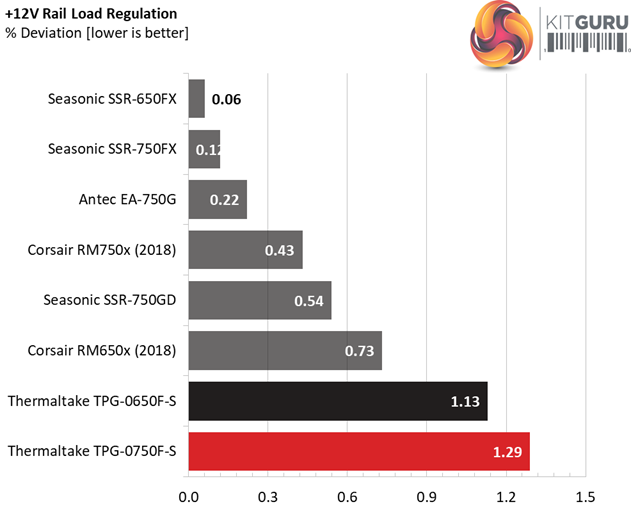
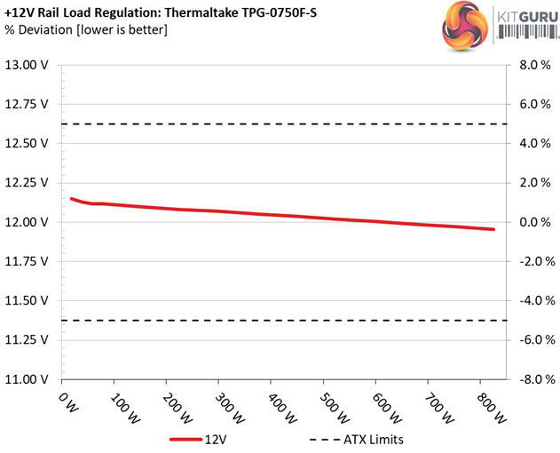
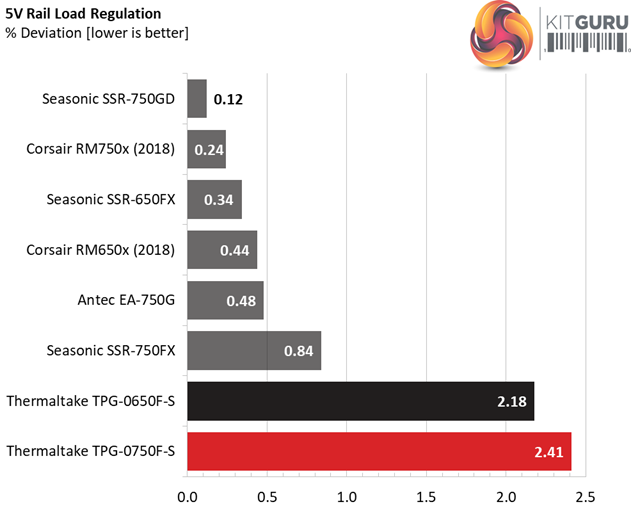
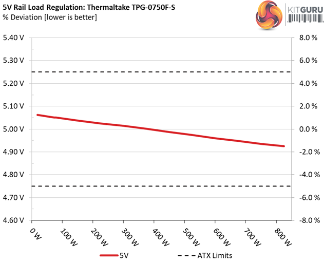
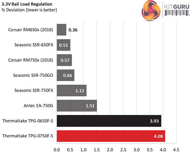
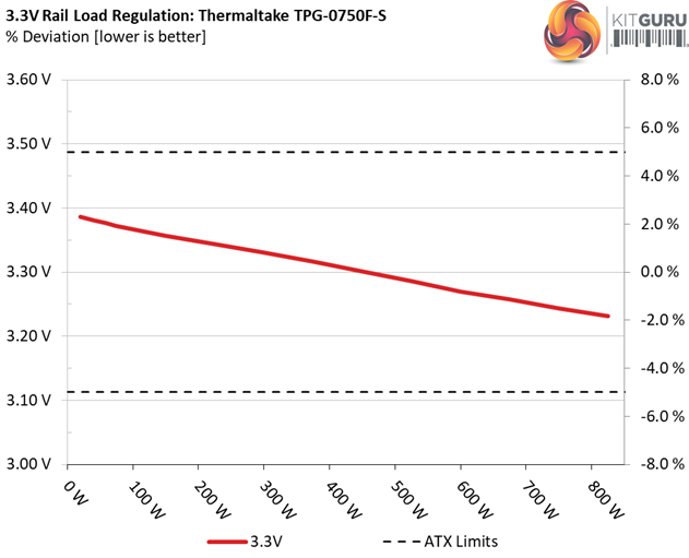
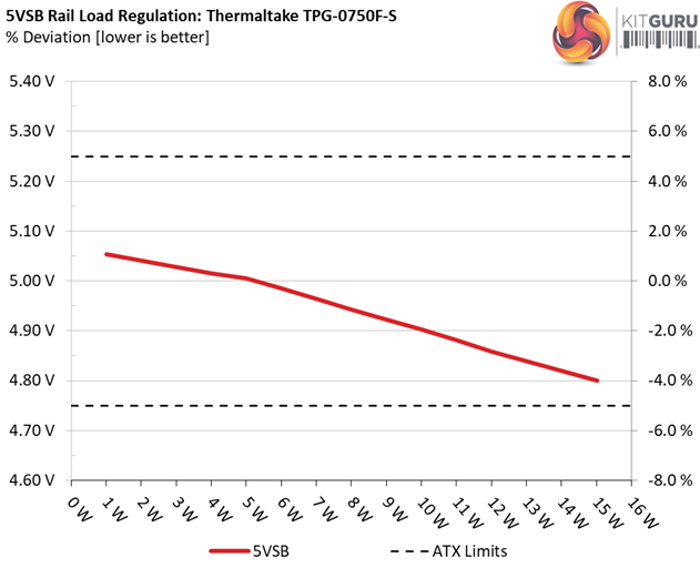
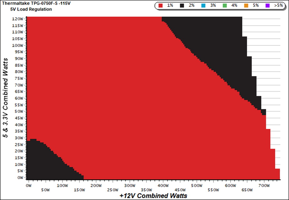
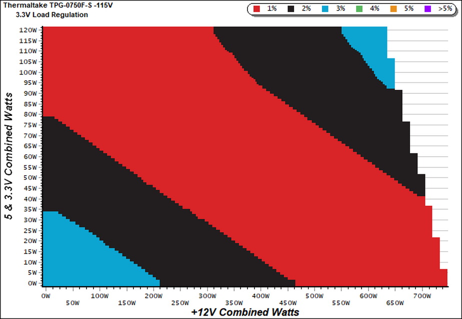
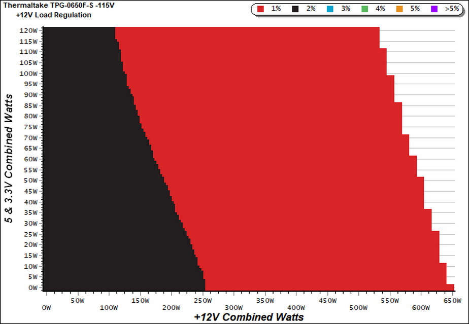
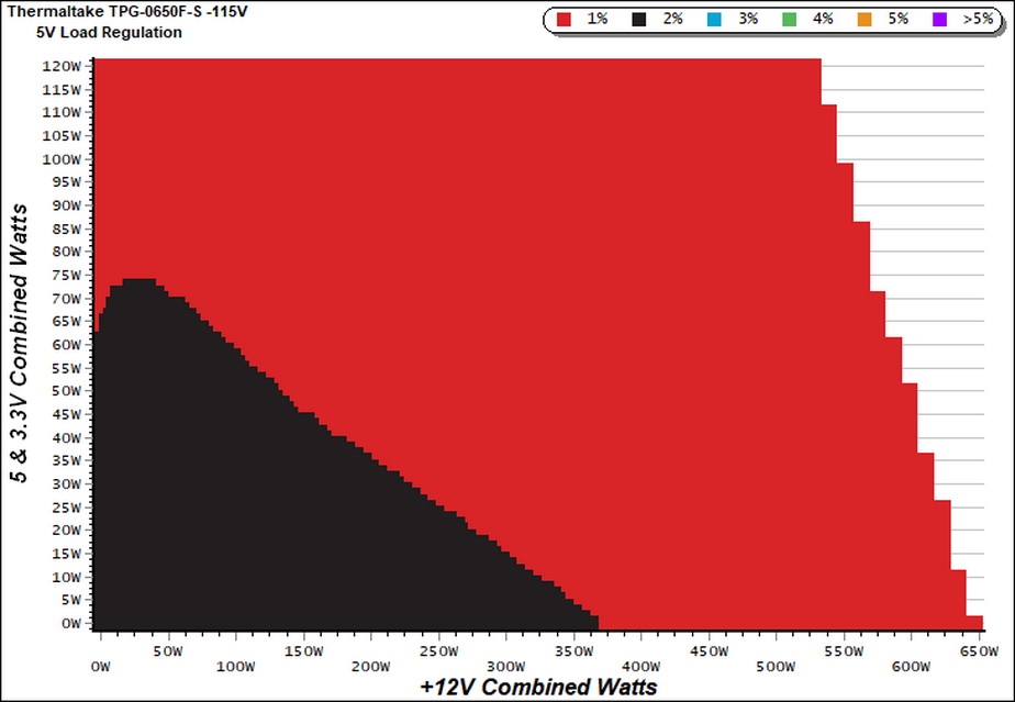
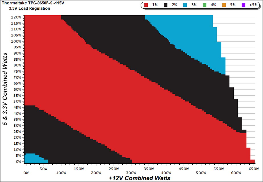
The load regulation at +12V is a bit loose, at 1.29%. The minor rails fall behind as well, compared to the competition, with the 5V, 3.3V and 5VSB rails registering 2.41%, 4.08% and 5.01% deviations, respectively. Obviously High Power didn't pay much attention in load regulation and this will surely affect the overall performance.
The 80 PLUS Gold requirements are easily met with 20% and 50% loads, while with full load the reading is very close to 87% despite of the tough conditions that we apply. This is an efficient platform which manages to keep the noise output low, even at high loads with the operating temperatures getting close to 47°C. The semi-passive operation doesn't last long once the temperatures start to rise, however the fan profile is very relaxed.
Efficiency
Our efficiency testing procedure is detailed here.
Using results from the previous page, we plotted a chart showing the TPG-750AH3FSGR’s efficiency at low loads, and loads from 10 to 110 percent of its maximum-rated capacity.
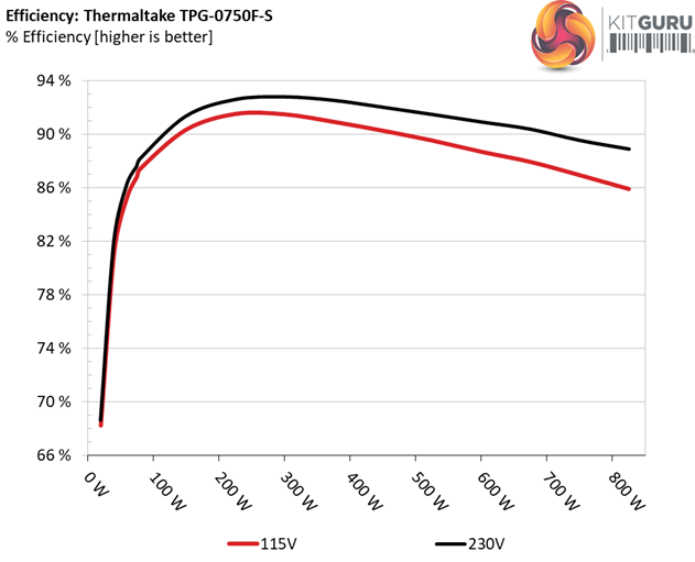
Both Thermaltake units have high efficiency under both light and normal loads, with their results being very close.
Efficiency At Low Loads
In the following tests, we measure the TPG-750AH3FSGR's efficiency at loads significantly lower than 10 percent of its maximum capacity (the lowest load the 80 PLUS standard measures). The loads we dial are 20, 40, 60, and 80W. This is important for representing when a PC is idle, with power-saving features turned on.
| Test # | 12V | 5V | 3.3V | 5VSB | DC/AC (Watts) | Efficiency | Fan Speed (RPM) | PSU Noise (dB[A]) | PF/AC Volts |
| 1 | 1.193A | 0.494A | 0.474A | 0.198A | 19.600 | 68.231% | 0 | <6.0 | 0.875 |
| 12.149V | 5.062V | 3.386V | 5.053V | 28.726 | 115.07V | ||||
| 2 | 2.450A | 0.989A | 0.977A | 0.397A | 40.019 | 81.224% | 0 | <6.0 | 0.906 |
| 12.128V | 5.058V | 3.381V | 5.041V | 49.270 | 115.06V | ||||
| 3 | 3.642A | 1.485A | 1.452A | 5.028A | 59.542 | 85.298% | 0 | <6.0 | 0.934 |
| 12.118V | 5.054V | 3.376V | 5.028V | 69.805 | 115.06V | ||||
| 4 | 4.900A | 1.981A | 1.959A | 0.798A | 79.973 | 87.460% | 0 | <6.0 | 0.951 |
| 12.115V | 5.050V | 3.371V | 5.015V | 91.440 | 115.05V |
We measure high efficiency under light loads. The passive operation also helps in this, since the fan doesn't consume any power and with such low loads even few Watts can make a difference.
5VSB Efficiency
The ATX specification (revision 1.4), along with CEC, ErP Lot 3 2014 and ErP Lot 6 2010/2013, states that the 5VSB standby supply efficiency should be as high as possible, recommending 75 percent or higher with 550mA, 1A, and 1.5A of load.
The supply should also achieve higher than 75% efficiency at 5VSB under full load, or with 3A if its max current output on this rail is higher than 3A.
We take six measurements: one each at 100, 250, 550, 1000, and 1500mA, and one with the full load the 5VSB rail can handle.
| Test # | 5VSB | DC/AC (Watts) |
Efficiency | PF/AC Volts |
| 1 | 0.100A | 0.510 | 74.020% | 0.082 |
| 5.089V | 0.689 | 115.06V | ||
| 2 | 0.250A | 1.271 | 77.358% | 0.166 |
| 5.082V | 1.643 | 115.06V | ||
| 3 | 0.550A | 2.788 | 80.000% | 0.250 |
| 5.068V | 3.485 | 115.06V | ||
| 4 | 1.000A | 5.048 | 80.331% | 0.300 |
| 5.047V | 6.284 | 115.06V | ||
| 5 | 1.500A | 7.536 | 80.256% | 0.326 |
| 5.023V | 9.390 | 115.06V | ||
| 6 | 3.000A | 14.843 | 77.700% | 0.364 |
| 4.947V | 19.103 | 115.06V |
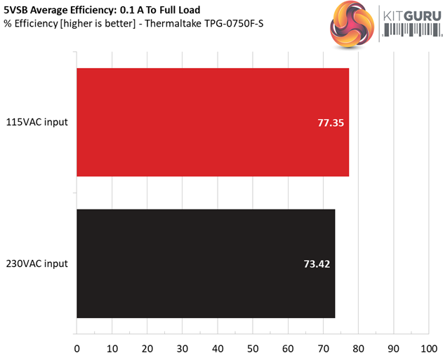
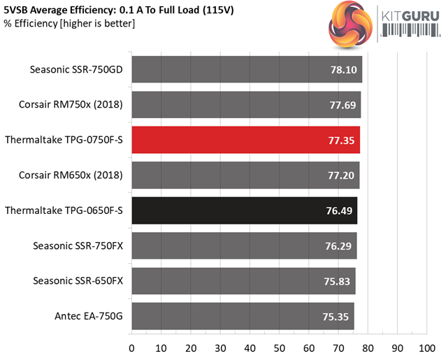
The 5VSB rail's efficiency is satisfactory with 115V, since we get three readings with 80% and higher efficiency levels. With 230V the registered efficiency levels are lower, as expected.
Power Consumption In Idle And Standby
In the table below, you’ll find the power consumption and voltage values of all rails (except -12V) when the PSU is idle (powered on, but without any load on its rails), and the power consumption when the unit is in standby mode (without any load, at 5VSB).
| Mode | 12V | 5V | 3.3V | 5VSB | Watts | PF/AC Volts |
| Idle | 12.196V | 5.067V | 3.392V | 5.067V | 5.930 | 0.474 |
| 115.1V | ||||||
| Standby | 0.089 | 0.011 | ||||
| 115.1V | ||||||
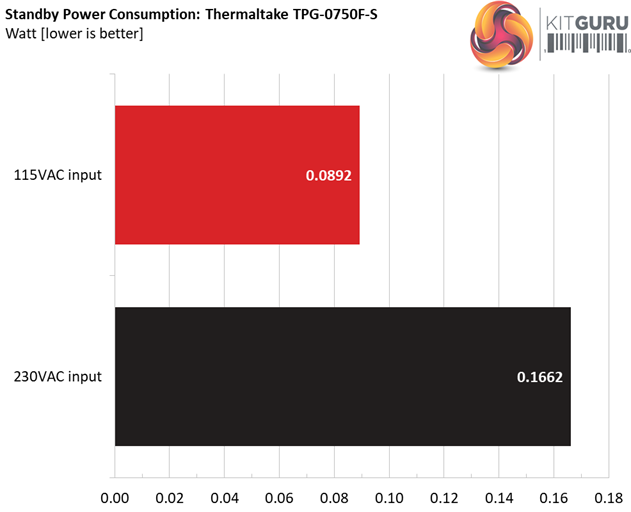
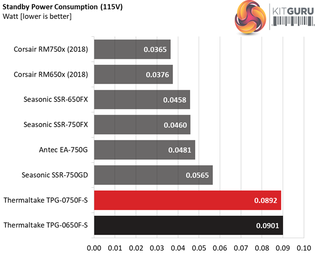
As you can see the vampire power levels are notably higher than the competition's. With lower power consumption in standby the 5VSB rail would be more efficient under light loads.
Fan RPM, Delta Temperature, And Output Noise
Our mixed noise testing is described in detail here.
The first chart below illustrates the cooling fan's speed (in RPM), and the delta between input and output temperature. The results were obtained at 37°C (98.6°F) to 47°C (116.6°F) ambient temperature.
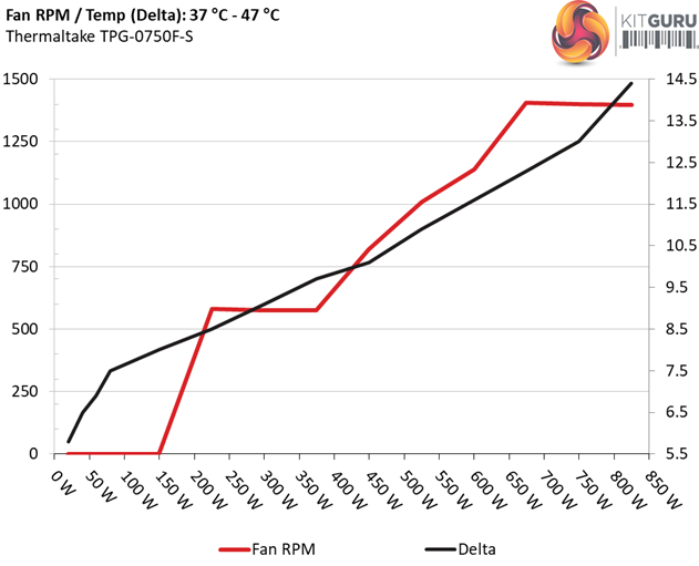
The next chart shows the cooling fan's speed (again, in RPM) and output noise. We measure acoustics from one meter away, inside a hemi-anechoic chamber.
Background noise inside the chamber is below 6 dB(A) during testing (it's actually much lower, but our sound meter’s microphone hits its floor), and the results are obtained with the PSU operating at 37°C (98.6°F) to 47°C (116.6°F) ambient temperature.
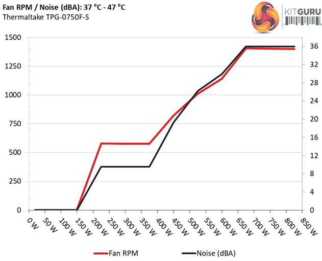
The following graph illustrates the fan's output noise over the PSU's operating range. The same conditions of the above graph apply to our measurements, though the ambient temperature is between 30°C (86°F) to 32°C (89.6°F).
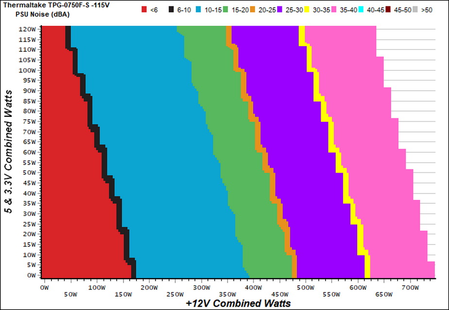
The semi-passive operation lasts till the load reaches 180W at +12V. The fan enters the noisy 35-40 dB(A) region with higher than 625W loads at +12V, and as you will notice the more the stress on the minor rails the higher the noise output.
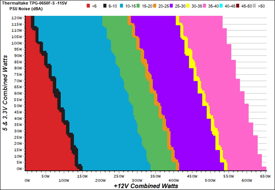
The 650W unit seems to have a similar fan speed profile with its large brother, adjusted of course to its lower capacity.
Protection Features
Our protection features evaluation methodology is described in detail here.
|
Protection Features TPG-750AH3FSGR |
|
|
OCP |
12V: 85.6A (136.96%), 11.9V |
|
OPP |
1042.9W (139.05%) |
|
OTP |
✓ (180°C @ 12V Heatsinks) |
|
SCP |
12V: ✓ |
|
PWR_OK |
Accurate (but lower than 16ms) |
|
NLO |
✓ |
|
SIP |
Surge: MOV |
The OCP at +12V and the over power protection are set a little higher than the ideal, which is 130%. The minor rails go pretty high, without any nasty surprises though. Nonetheless, from the moment the 5V and 3.3V rails are only lightly used it should be better if their OCP thresholds were set lower.
The over temperature protection is there, shutting down the PSU once the temperature on the +12V heatsinks goes above 180°C. Moreover, there is short circuit protection on all rails and the power ok signal is accurate.
|
Protection Features TPG-650AH3FSGR |
|
|
OCP |
12V: 75.6A (139.48%), 11.963V |
|
OPP |
922.9W (141.98%) |
|
OTP |
✓ (170°C @ 12V Heatsink) |
|
SCP |
12V: ✓ |
|
PWR_OK |
Accurate (but lower than 16ms) |
|
NLO |
✓ |
|
SIP |
Surge: MOV |
The 650W model has a similar OPP threshold with the 750W unit, at close to 140% of the max-rated-output. The over current protection on all rails is set a little higher than the ideal (130%), while the over temperature protection kicked in at 10°C lower, at 170°C.
The power ok signal is accurate but lower than 16ms and there is short circuit protection on all rails. In today's PSUs this protection might be a typical feature, however we have encountered cases where even high-end units broke down once we short circuited their rails. Those platforms were defective of course, since SCP is absolutely necessary in every PSU out there.
DC Power Sequencing
According to Intel’s most recent Power Supply Design Guide (revision 1.4) the +12V and 5V voltages must be equal or greater than the 3.3V rail’s output at all times, during the power-up and normal operation. For our first measurement, we turn the unit off and switch it back on without any load in any of the rails.
In the second test, we set the PSU to standby mode, dial full load and start it afterwards. In the last test, while the power supply is completely switched off (we cut off the power or switch the supply off through its power switch), we dial full load before restoring power.
The 3.3V rail's voltage is always lower than 5V and 12V, so everything is fine here.
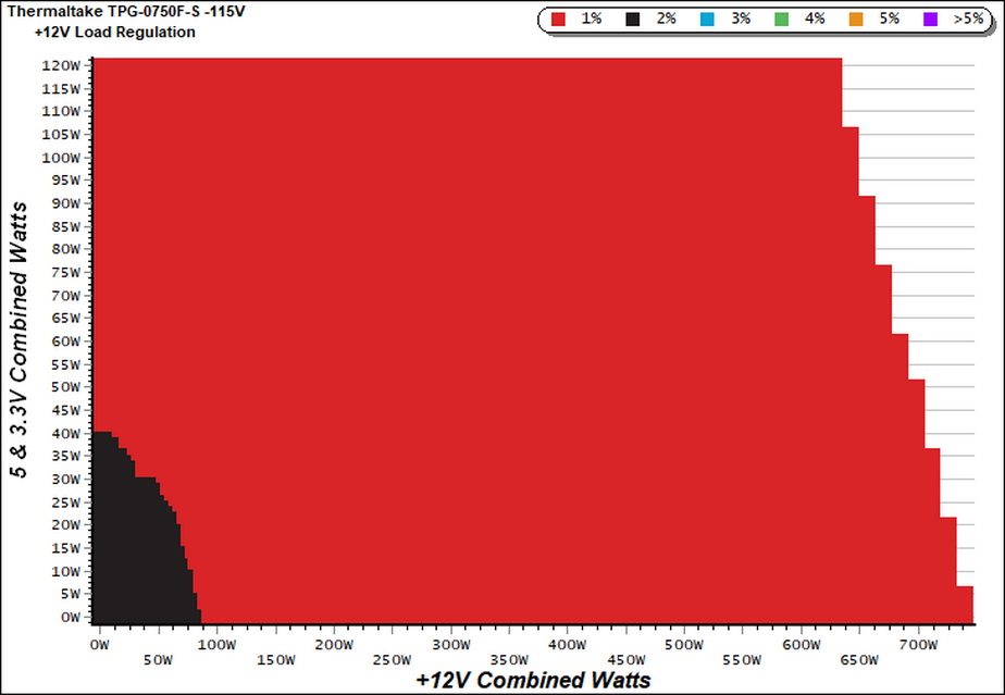
Our cross-load tests are described in detail here.
To generate the following charts, we set our loaders to auto mode through our custom-made software before trying more than 1500 possible load combinations with the +12V, 5V, and 3.3V rails. The load regulation deviations in each of the charts below are calculated by taking the nominal values of the rails (12V, 5V, and 3.3V) as point zero. The ambient temperature is between at 30°C (86°F) to 32°C (89.6°F).
Load Regulation Charts
Efficiency Chart
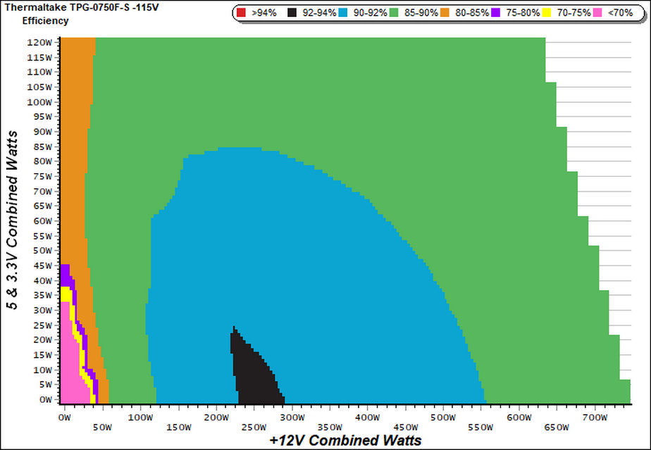
There is a small region with the efficiency going over 92%. This is something that we usually see in units with higher efficiency certifications (e.g. Platinum).
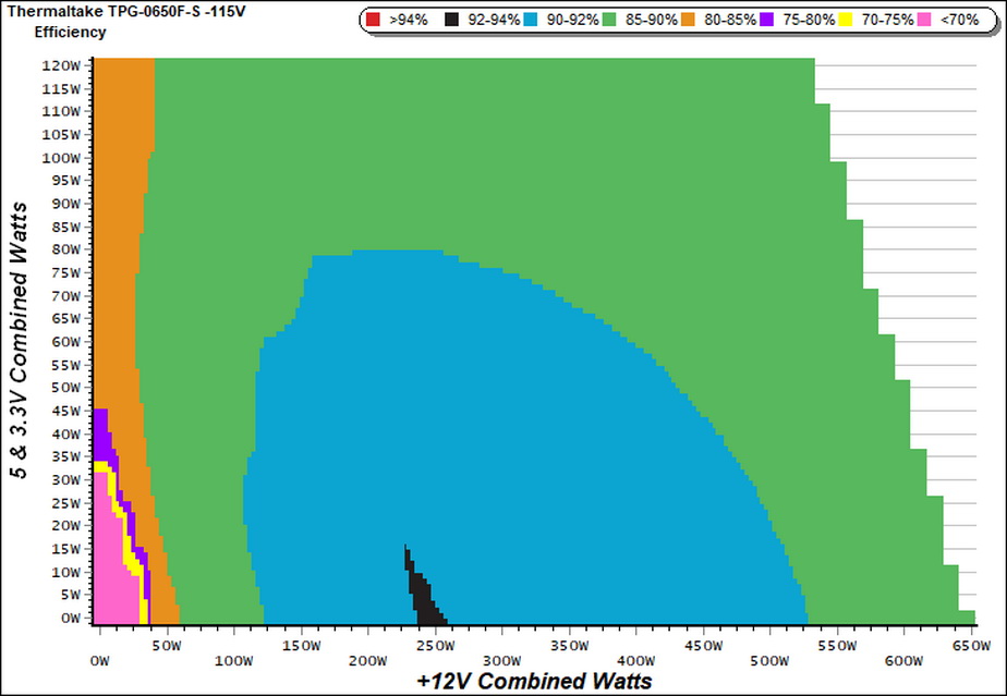
The 650W model also surpasses 92% efficiency, however this operating region is smaller compared to its big brother.
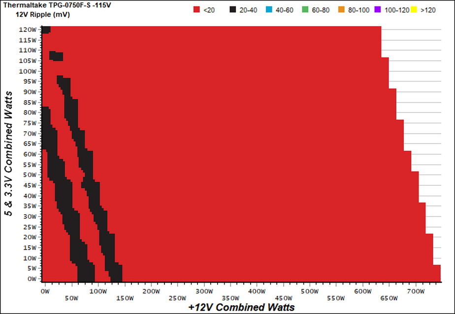
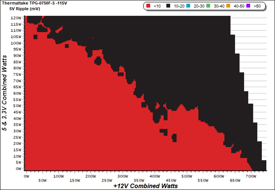
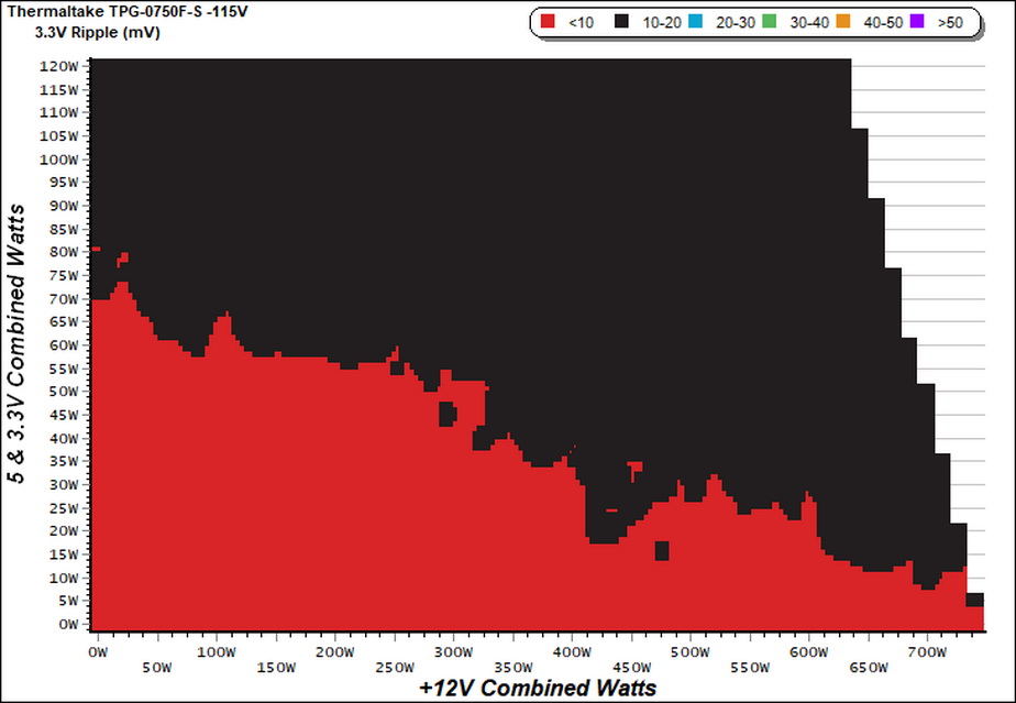
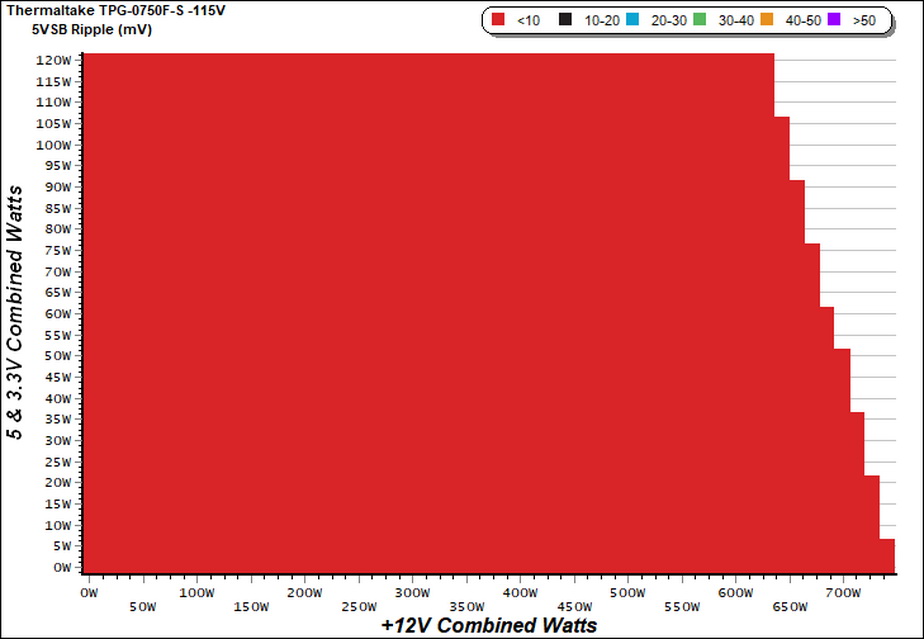
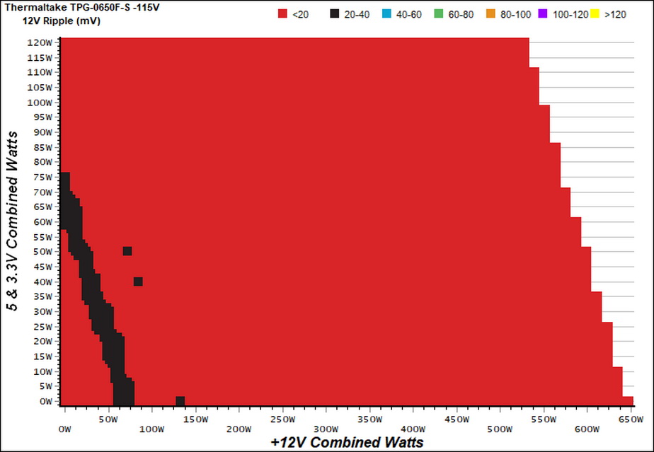
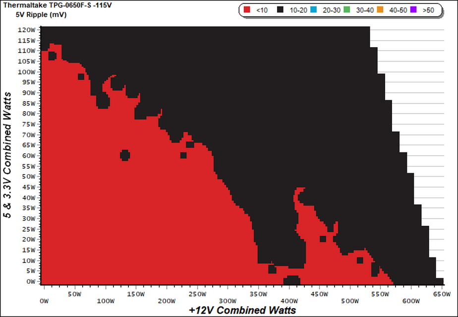
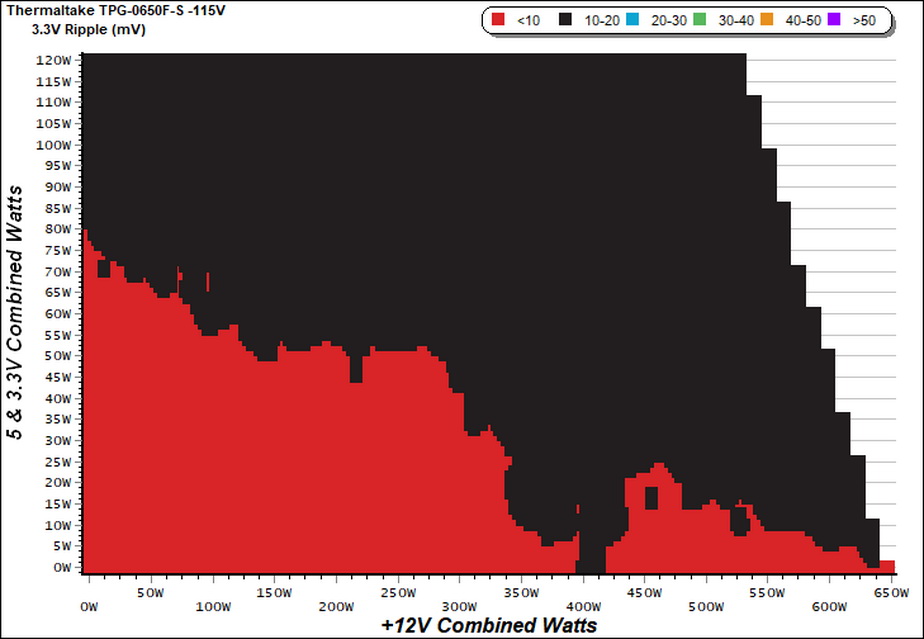
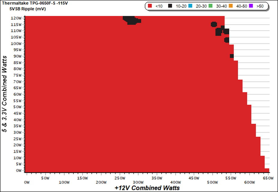
Ripple Charts
Infrared Images
We apply half-load for 10 minutes with the PSU’s top cover and cooling fan removed before taking photos with our modified FLIR E4 camera that delivers 320×240 IR resolution (76,800 pixels).
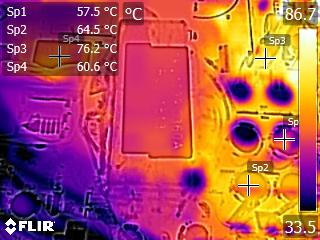
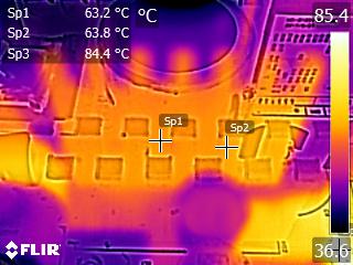
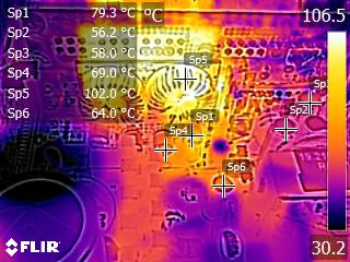
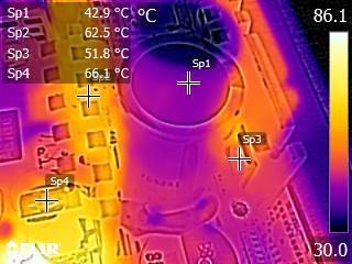
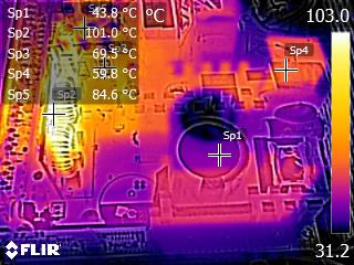
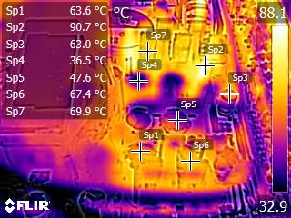
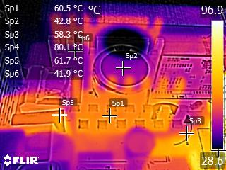
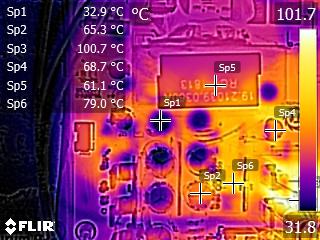
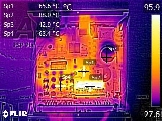
The temperature of the bulk cap stays low, however the VRMs get quite hot since we apply more than 10 Amps load in each of the minor rails. The temperatures of the polymer caps on the VRMs' daughter-board are increased as well, but this type of caps are tolerant to high temperatures.
Advanced Transient Response Tests
For details on our transient response testing, please click here.
These tests are crucial because they simulate the transient loads a PSU is likely to handle (such as booting a RAID array or an instant 100 percent load of CPU/GPUs). We call these “Advanced Transient Response Tests” and they are designed to be very tough to master, especially for a PSU with a capacity of less than 500W.
In all of the tests, we use an oscilloscope to measure the voltage drops caused by the transient load. The voltages should remain within the ATX specification's regulation limits.
We should note that the ATX spec requires for capacitive loading during the transient rests, but in our methodology we chose to apply the worst case scenario with no extra capacitance on the rails.
Advanced Transient Response at 20 Percent – 200ms
| Voltage | Before | After | Change | Pass/Fail |
|---|---|---|---|---|
| 12V | 12.090V | 11.859V | 1.91% | Pass |
| 5V | 5.035V | 4.860V | 3.48% | Pass |
| 3.3V | 3.355V | 3.131V | 6.68% | Fail |
| 5VSB | 4.983V | 4.892V | 1.83% | Pass |
Advanced Transient Response at 20 Percent – 20ms
| Voltage | Before | After | Change | Pass/Fail |
|---|---|---|---|---|
| 12V | 12.091V | 11.769V | 2.66% | Pass |
| 5V | 5.036V | 4.828V | 4.13% | Pass |
| 3.3V | 3.356V | 3.139V | 6.47% | Fail |
| 5VSB | 4.984V | 4.902V | 1.65% | Pass |
Advanced Transient Response at 20 Percent – 1ms
| Voltage | Before | After | Change | Pass/Fail |
|---|---|---|---|---|
| 12V | 12.090V | 11.729V | 2.99% | Pass |
| 5V | 5.036V | 4.839V | 3.91% | Pass |
| 3.3V | 3.356V | 3.100V | 7.63% | Fail |
| 5VSB | 4.985V | 4.860V | 2.51% | Pass |
Advanced Transient Response at 50 Percent – 200ms
| Voltage | Before | After | Change | Pass/Fail |
|---|---|---|---|---|
| 12V | 12.047V | 11.923V | 1.03% | Pass |
| 5V | 5.000V | 4.817V | 3.66% | Pass |
| 3.3V | 3.316V | 3.088V | 6.88% | Fail |
| 5VSB | 4.925V | 4.827V | 1.99% | Pass |
Advanced Transient Response at 50 Percent – 20ms
| Voltage | Before | After | Change | Pass/Fail |
|---|---|---|---|---|
| 12V | 12.047V | 11.870V | 1.47% | Pass |
| 5V | 5.001V | 4.818V | 3.66% | Pass |
| 3.3V | 3.317V | 3.069V | 7.48% | Fail |
| 5VSB | 4.926V | 4.842V | 1.71% | Pass |
Advanced Transient Response at 50 Percent – 1ms
| Voltage | Before | After | Change | Pass/Fail |
|---|---|---|---|---|
| 12V | 12.047V | 11.892V | 1.29% | Pass |
| 5V | 5.000V | 4.826V | 3.48% | Pass |
| 3.3V | 3.317V | 3.068V | 7.51% | Fail |
| 5VSB | 4.926V | 4.829V | 1.97% | Pass |
![]()
![]()
![]()
![]()
![]()
Given the not good load regulation we expected to see mediocre results in the transient response tests, and indeed this is the case. Both models are far away from the competition's results. High Power should work on this platform's transient response, since under real life conditions PSUs have to constantly cope with transient loads.
Here are the oscilloscope screenshots we took during Advanced Transient Response Testing:
Transient Response At 20 Percent Load – 200ms
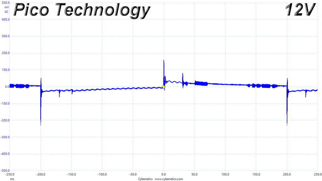
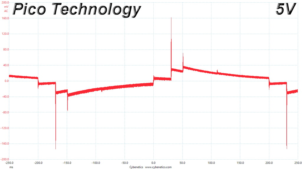
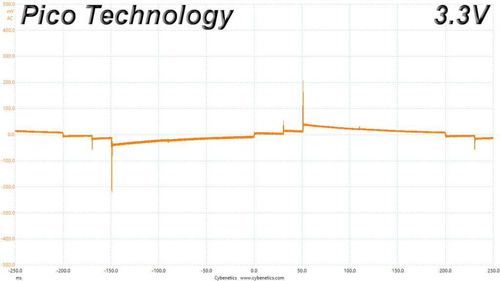
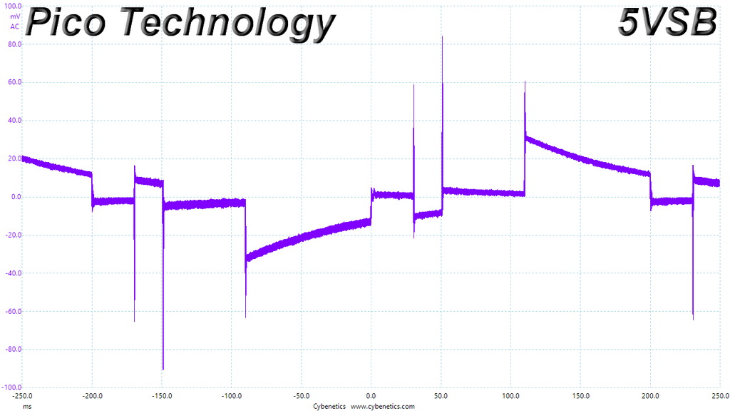
Transient Response At 20 Percent Load – 20ms
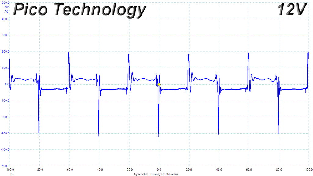
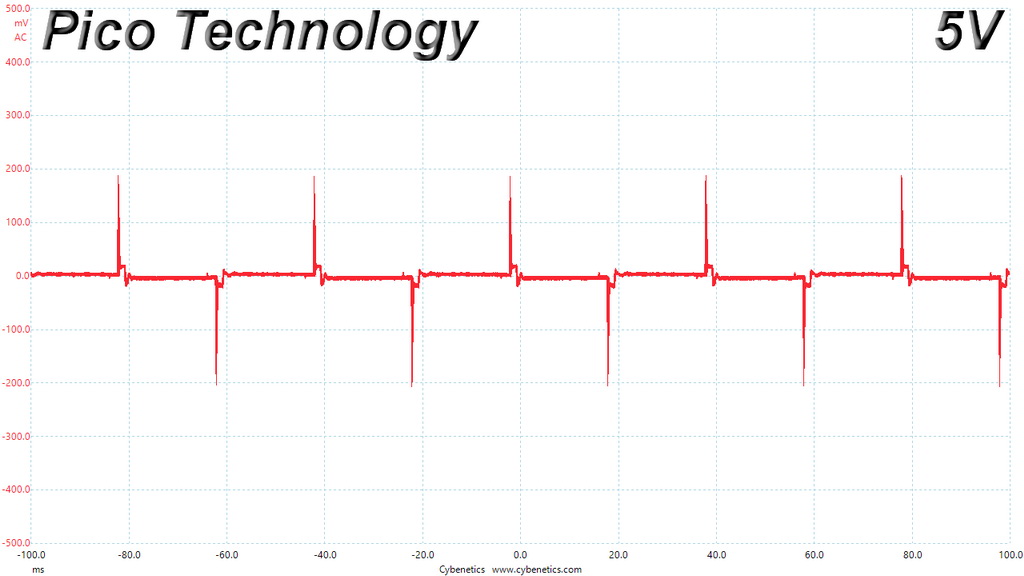
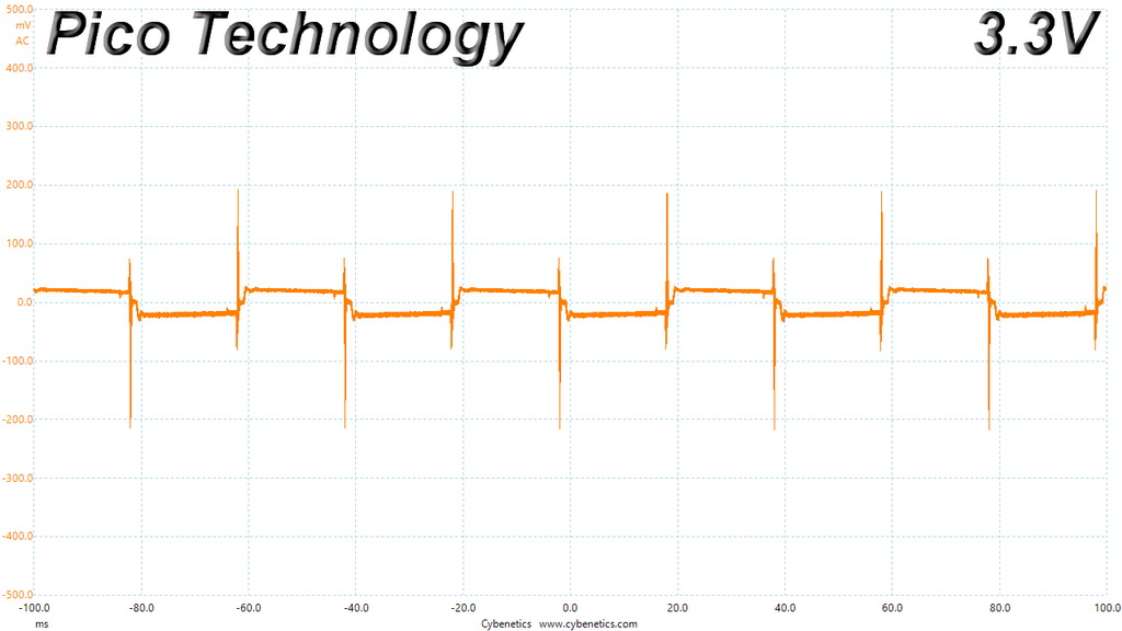
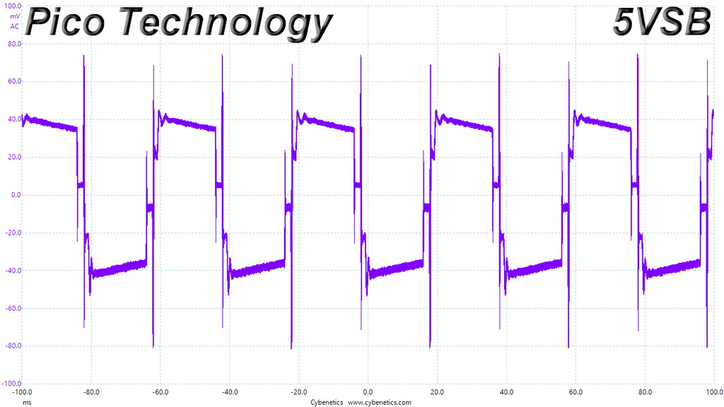
Transient Response At 20 Percent Load – 1ms
Transient Response At 50 Percent Load – 200ms
Transient Response At 50 Percent Load – 20ms
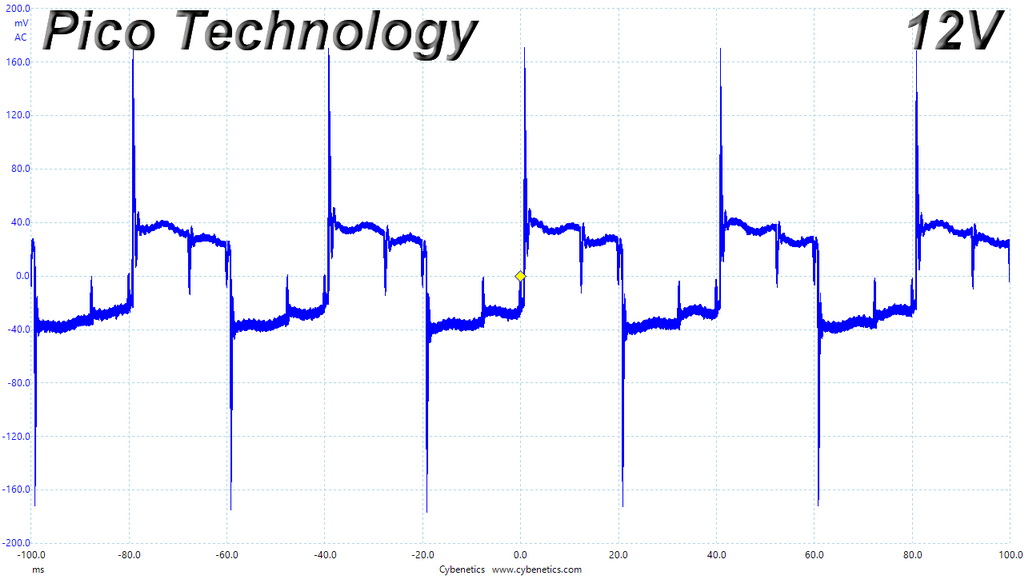
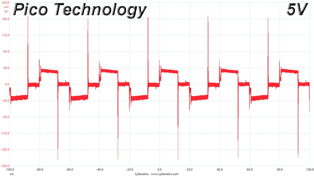
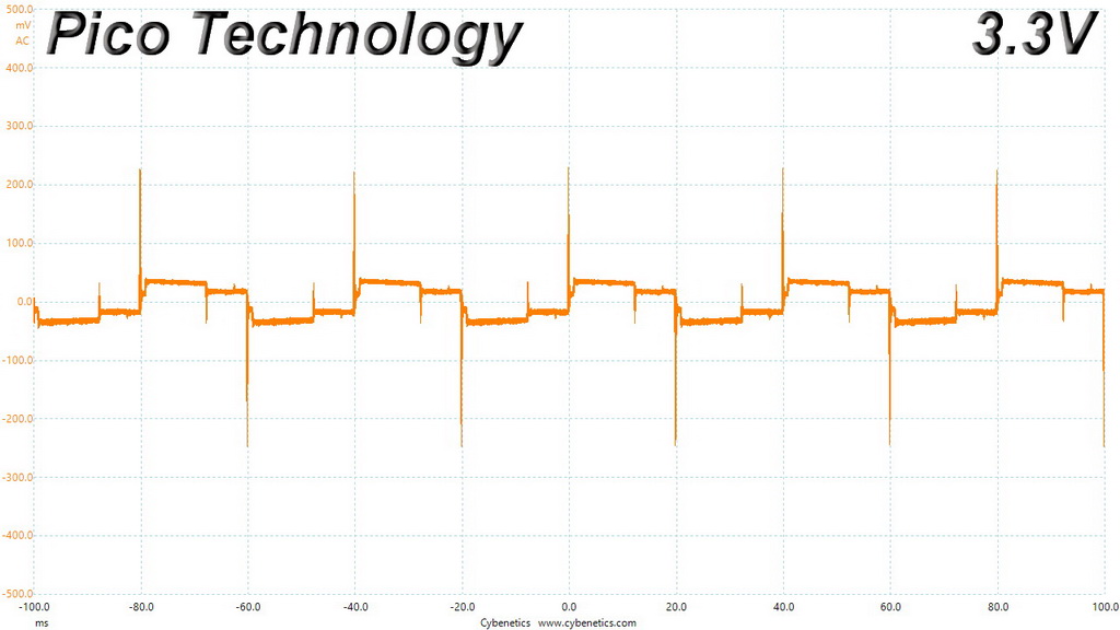

Transient Response At 50 Percent Load – 1ms

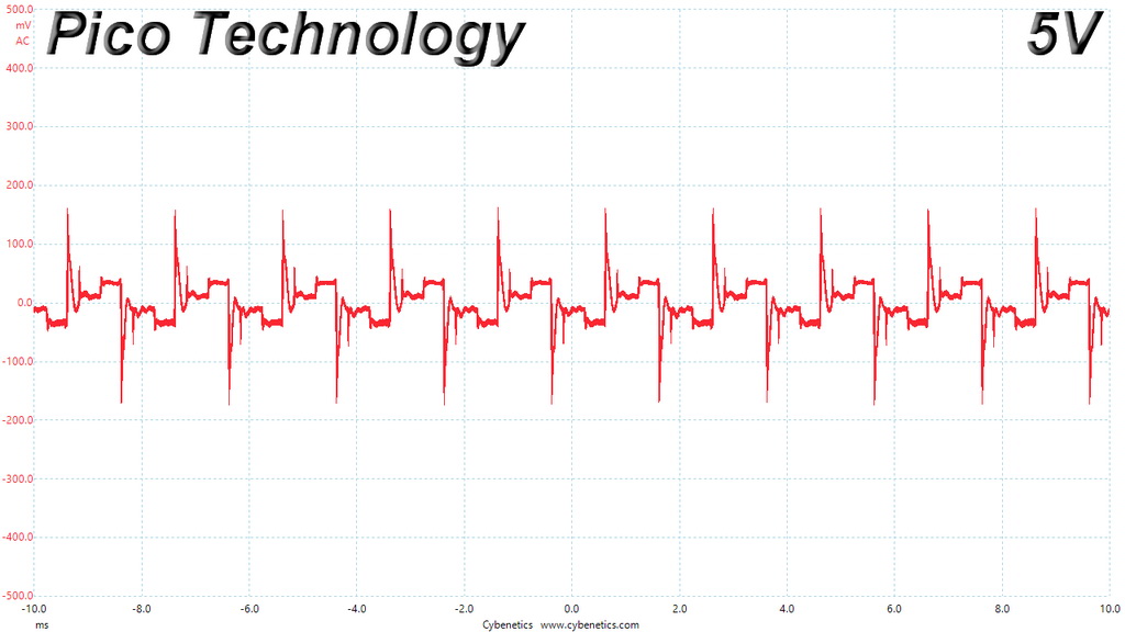
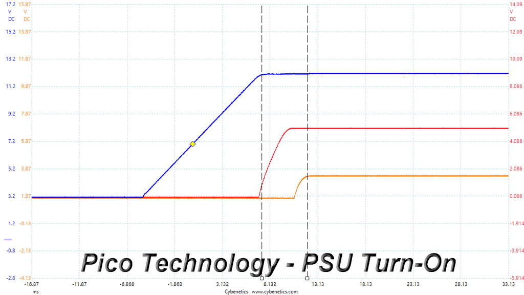
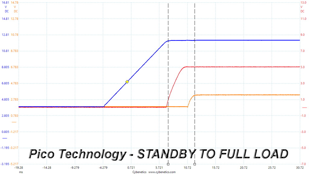
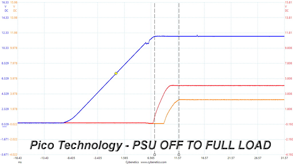
Turn-On Transient Tests
In the next set of tests, we measure the TPG-750AH3FSGR’s response in simpler transient load scenarios—during its power-on phase.
For our first measurement, we turn the PSU off, dial in the maximum current the 5VSB rail can handle, and switch the power supply back on.
In the second test, we dial the maximum load the +12V rail can handle and start the PSU while it is in standby mode. In the last test, while the PSU is completely switched off (we cut off the power or switch the PSU off through its power switch), we dial the maximum load the +12V rail can handle before restoring power. The ATX specification states that recorded spikes on all rails should not exceed 10 percent of their nominal values (+10 percent for 12V is 13.2V, and 5.5V for 5V).
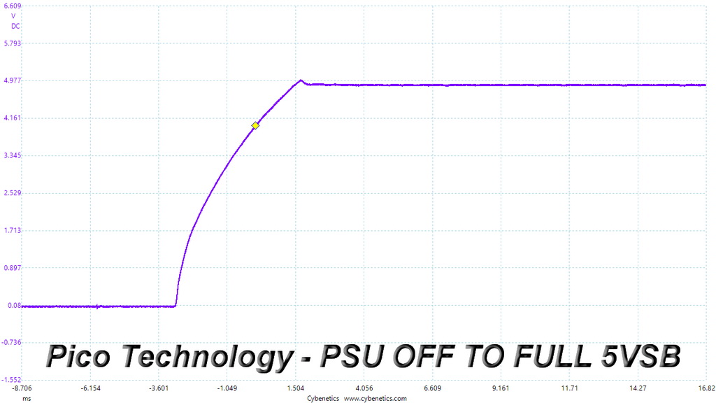

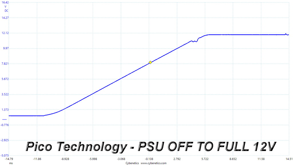
There is only a small spike at 5VSB, with the rest two test results being almost perfect.
To learn how we measure ripple, please click here.
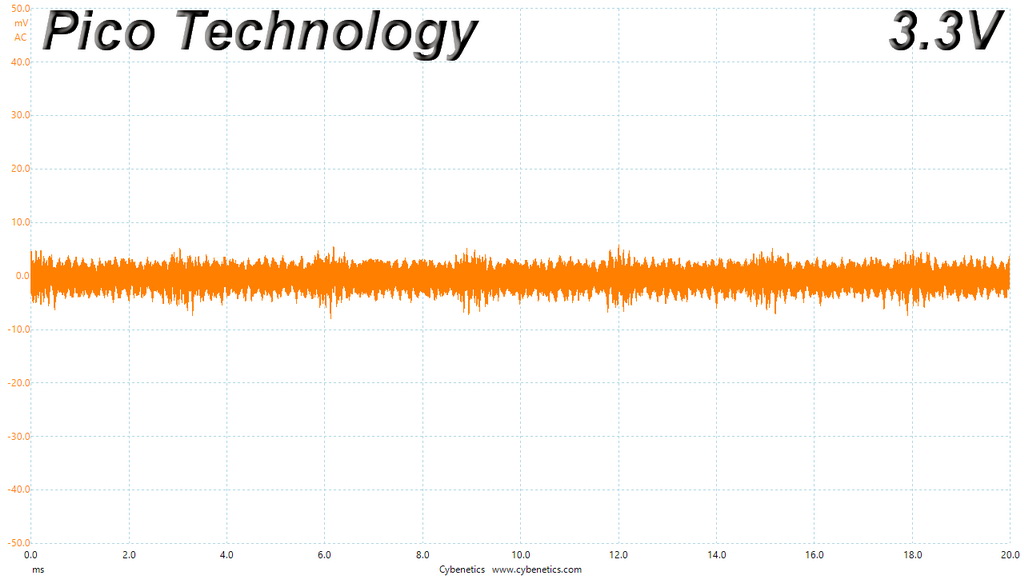
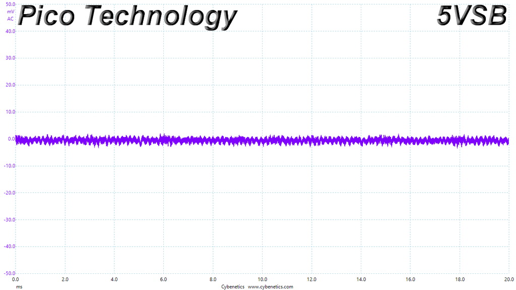
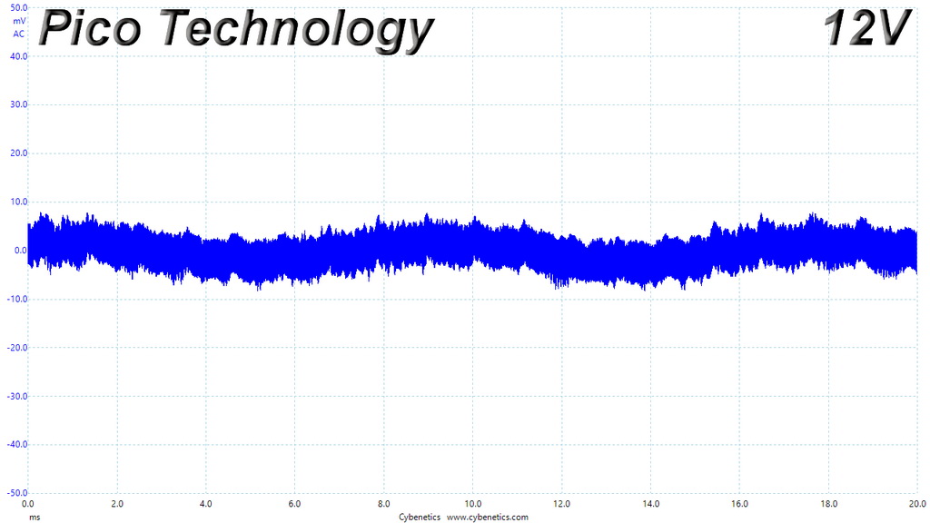
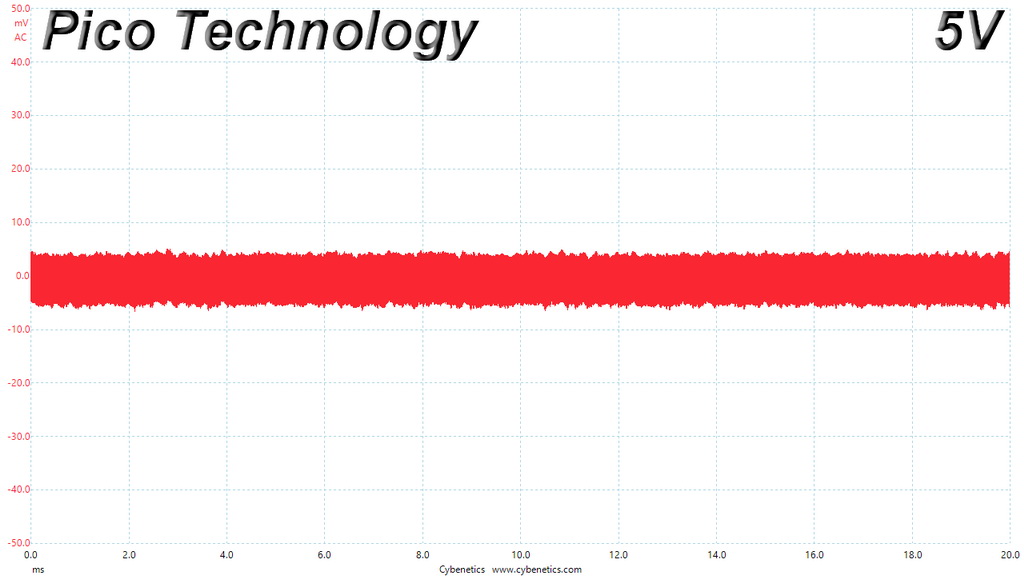
The following table includes the ripple levels we measured on the TPG-750AH3FSGR’s rails. The limits, according to the ATX specification, are 120mV (+12V) and 50mV (5V, 3.3V, and 5VSB).
| Test | 12V | 5V | 3.3V | 5VSB | Pass/Fail |
| 10% Load | 29.7 mV | 6.1 mV | 6.6 mV | 4.3 mV | Pass |
| 20% Load | 26.8 mV | 7.0 mV | 8.5 mV | 4.4 mV | Pass |
| 30% Load | 9.9 mV | 7.3 mV | 9.3 mV | 4.5 mV | Pass |
| 40% Load | 11.9 mV | 8.6 mV | 9.9 mV | 5.7 mV | Pass |
| 50% Load | 11.9 mV | 10.1 mV | 11.0 mV | 6.0 mV | Pass |
| 60% Load | 12.7 mV | 13.0 mV | 12.9 mV | 9.2 mV | Pass |
| 70% Load | 14.2 mV | 12.5 mV | 12.9 mV | 7.4 mV | Pass |
| 80% Load | 15.4 mV | 14.6 mV | 14.7 mV | 8.7 mV | Pass |
| 90% Load | 16.8 mV | 15.3 mV | 15.8 mV | 9.5 mV | Pass |
| 100% Load | 18.8 mV | 16.6 mV | 16.7 mV | 10.5 mV | Pass |
| 110% Load | 19.9 mV | 17.5 mV | 17.4 mV | 10.3 mV | Pass |
| Crossload 1 | 22.7 mV | 12.4 mV | 14.4 mV | 6.1 mV | Pass |
| Crossload 2 | 18.3 mV | 12.3 mV | 11.3 mV | 8.1 mV | Pass |
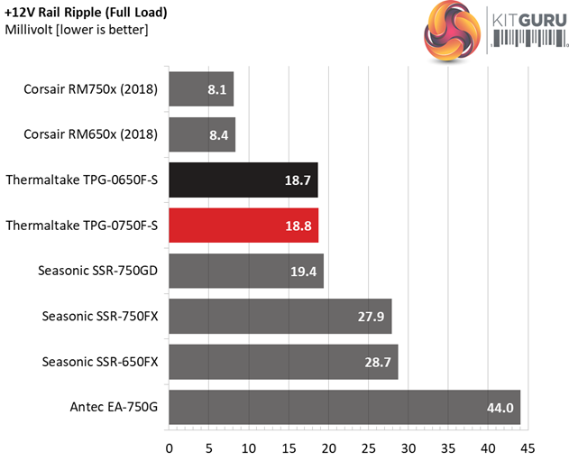
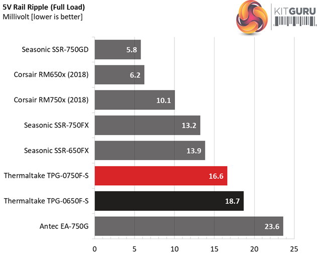
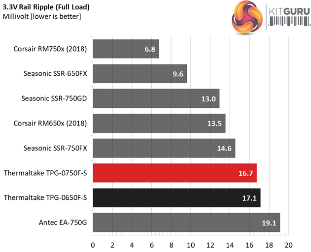
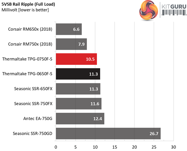
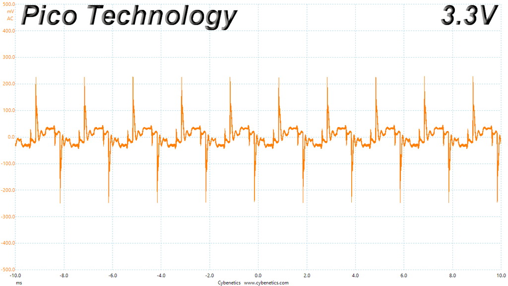
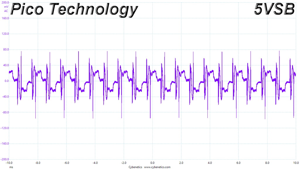
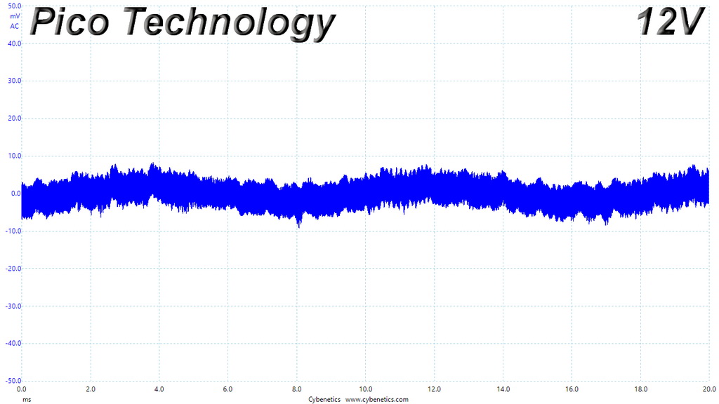
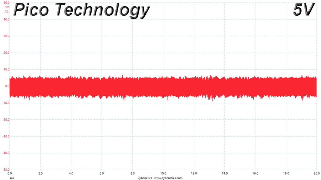
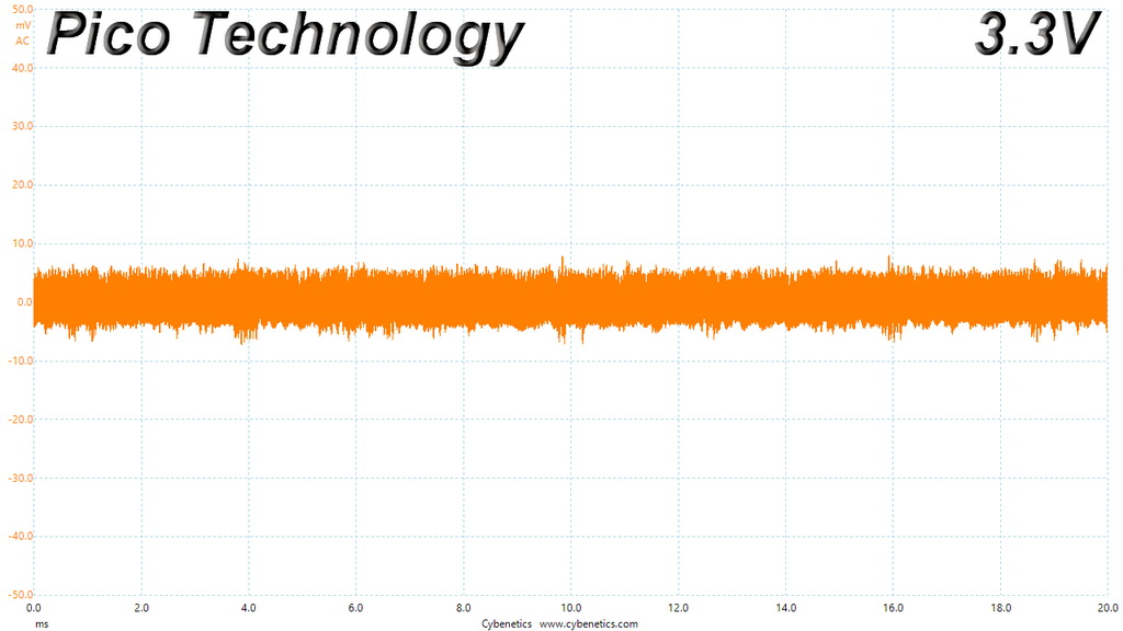
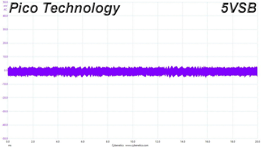
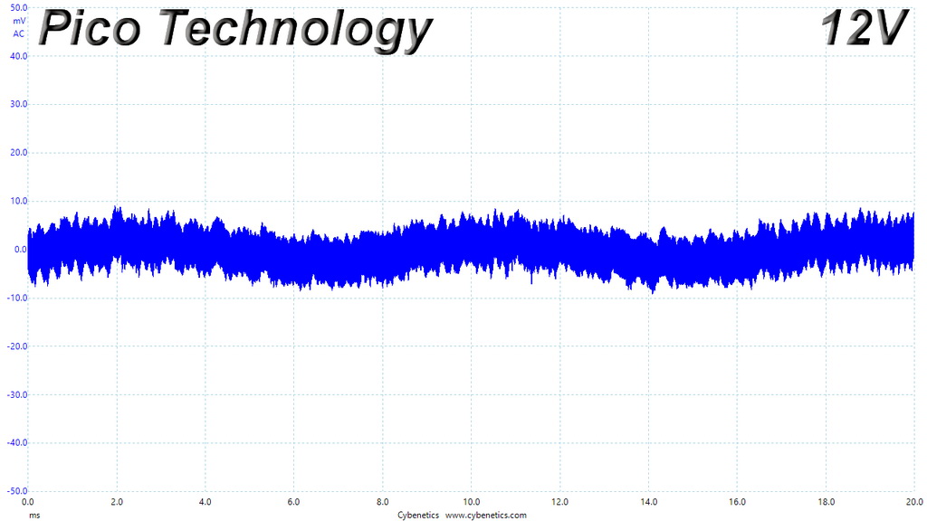
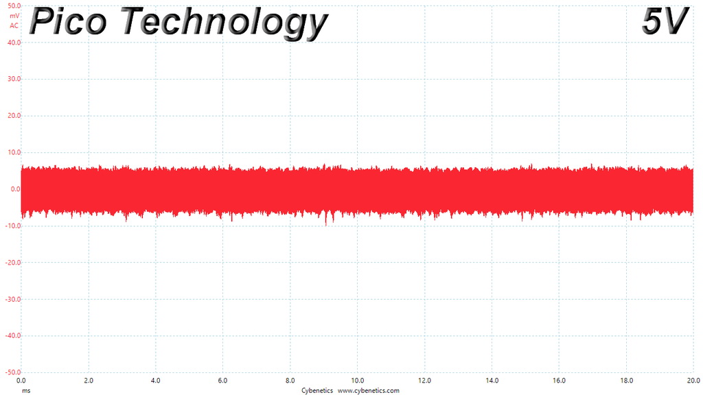
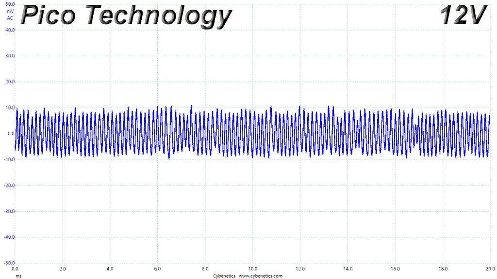
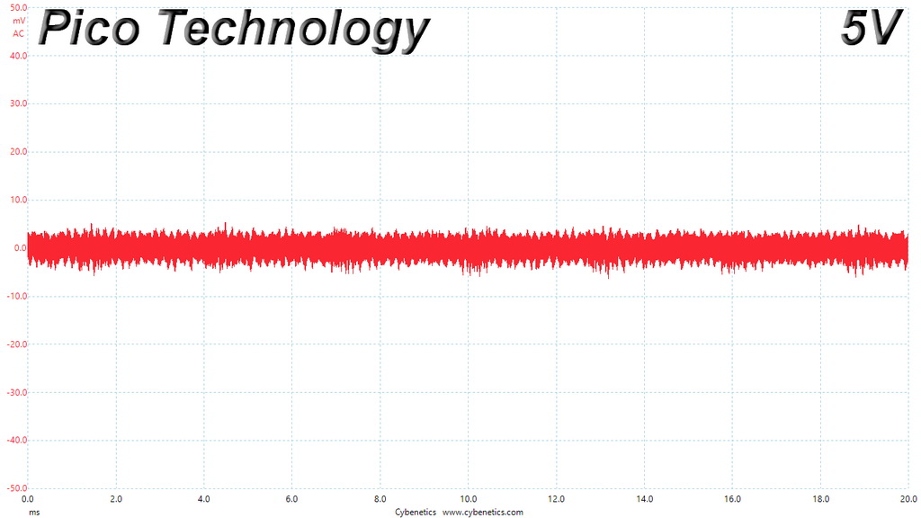
The unit delivers clean rails. We might not see the perfect results that Corsair's units deliver, but still all rails stay below 20mV ripple with full load at 47°C.
Ripple Oscilloscope Screenshots
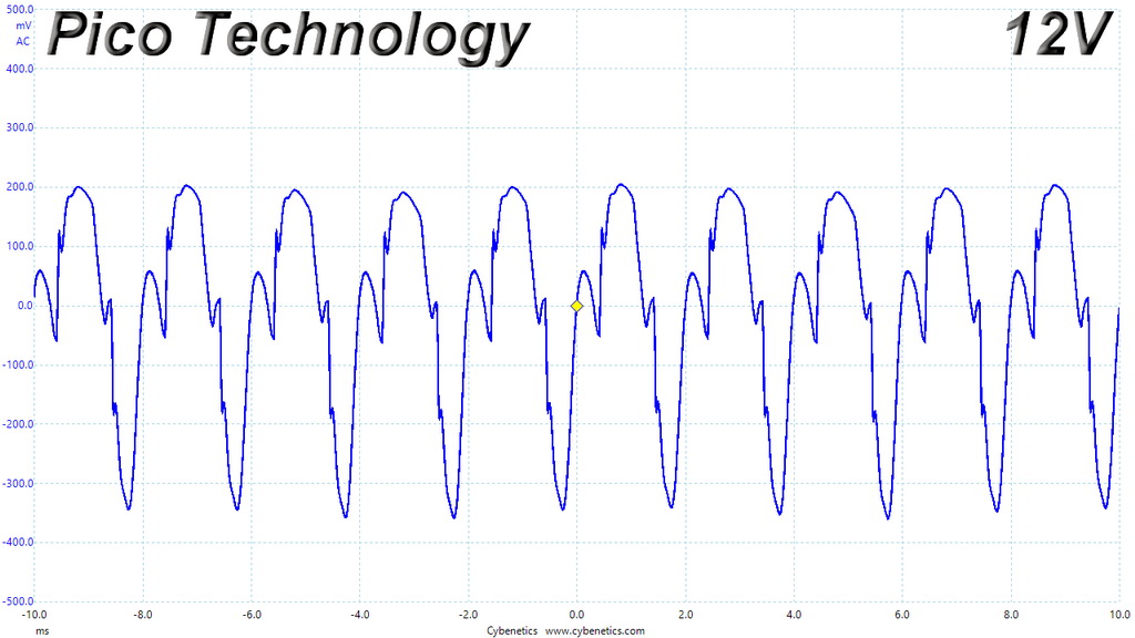
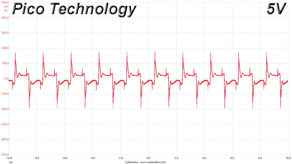
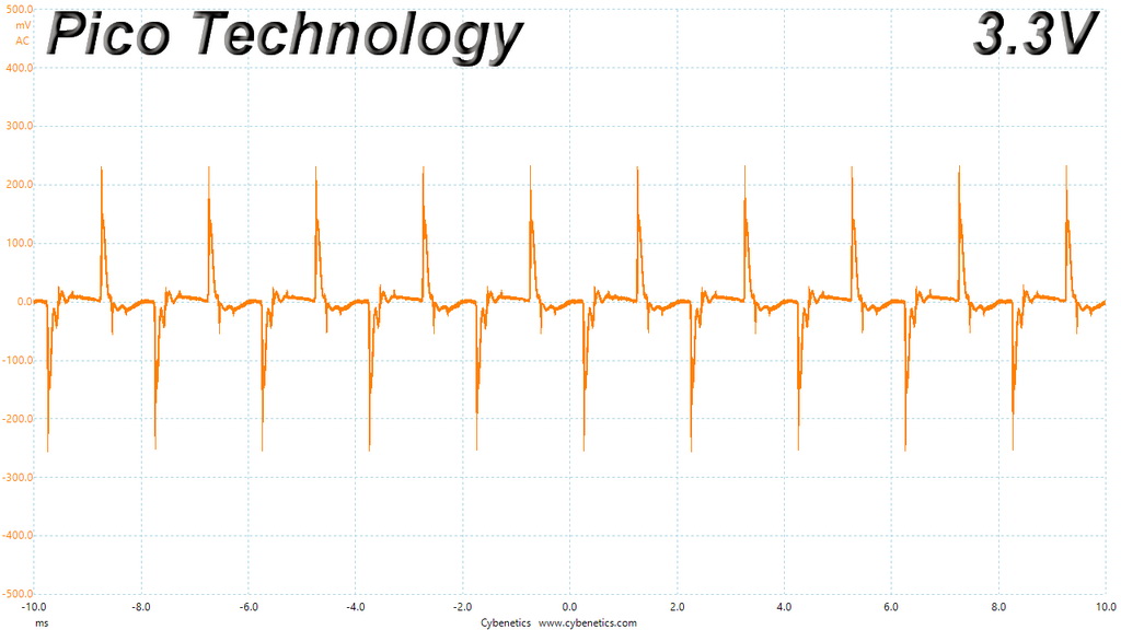
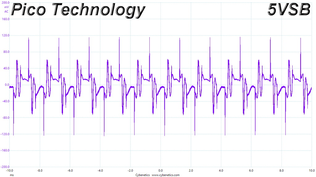
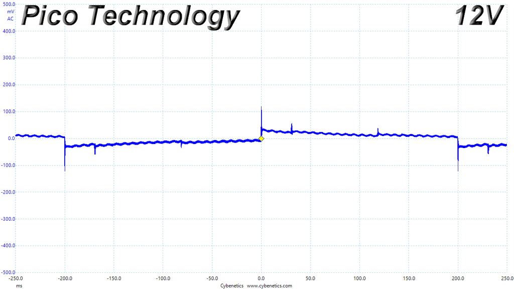
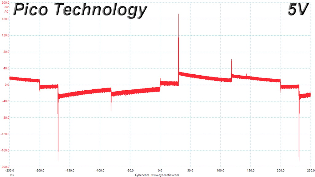
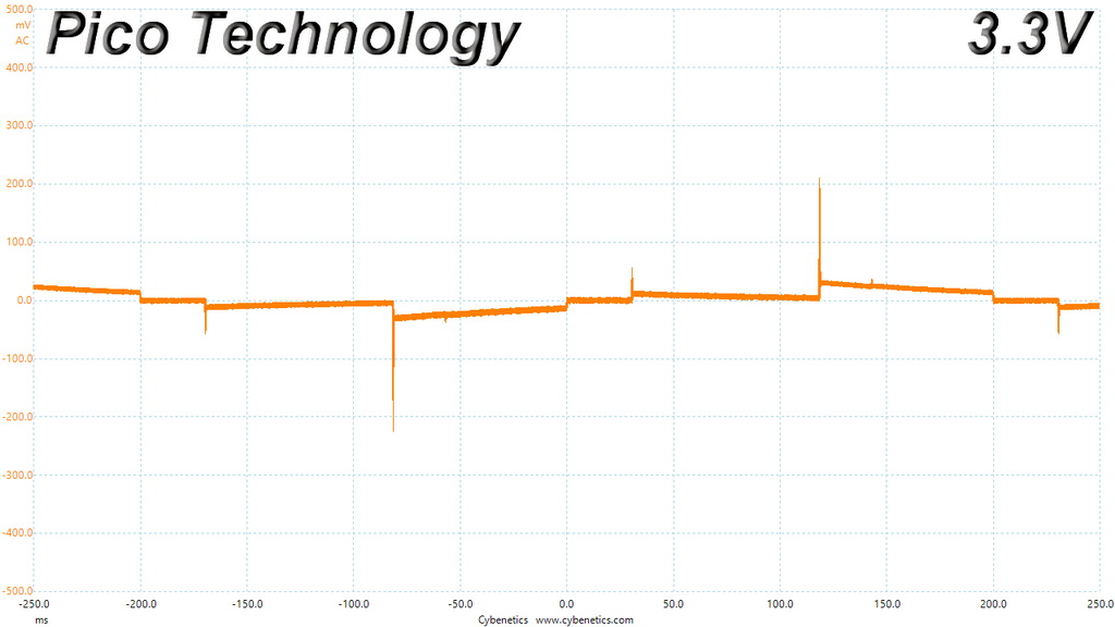
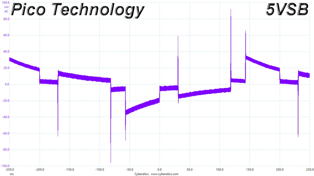
The following oscilloscope screenshots illustrate the AC ripple and noise registered on the main rails (+12V, 5V, 3.3V and 5VSB). The bigger the fluctuations on the screen, the bigger the ripple/noise. We set 0.01 V/Div (each vertical division/box equals 0.01V) as the standard for all measurements.
Ripple At Full Load
Ripple At 110-Percent Load


Ripple At Cross-Load 1
Ripple At Cross-Load 2

To learn more about our EMI testing equipment, please check out How We Test Power Supply Units.
EMI Results – Average & Peak
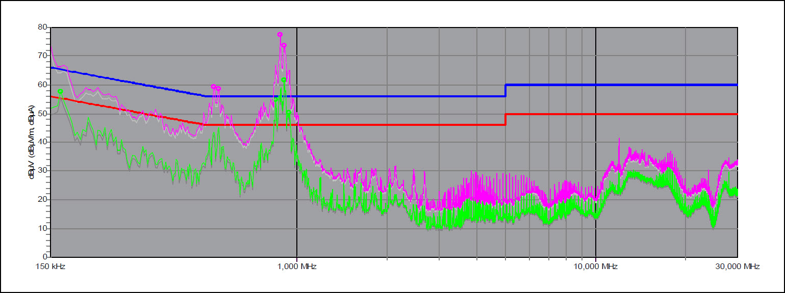
We see two high spurs below 1MHz, with one of them going well above the limits. The limits are also crossed at 162KHz frequency. The EMI filter needs some tuning, to stay within the limits of the CISPR 32 Class B standard.
Performance Rating
The following graph shows the TPG-750AH3FSGR’s total performance rating, comparing it to other units we have tested. To be more specific, the tested unit is shown as 100 percent, and every other unit's performance is shown relative to it.
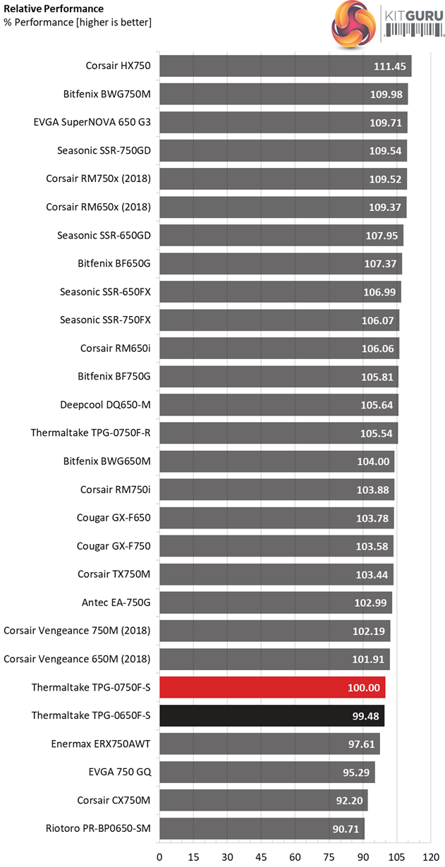
The overall performance is not that high, with the RM750x and the SSR-750FX being far away. The 650W model follows closely the 750W unit.
Performance Per Dollar
The following chart may be the most interesting to many of you because it depicts the product’s performance-per-dollar score. We looked up the current price of each PSU on popular online shops and used those prices and all relative performance numbers to calculate the index. Note that all of the numbers in the following graphs are normalized by the rated power of each unit.
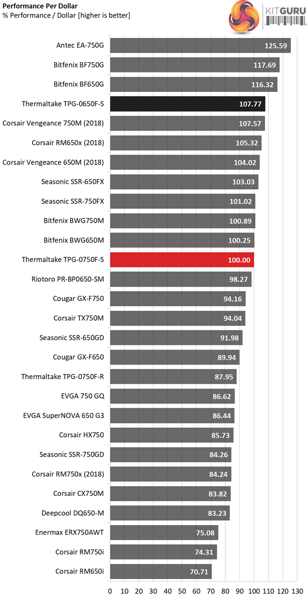
The lower capacity model achieves a higher price per buck score, thanks to its lower price.
Noise Rating
The graph below depicts the cooling fan's average noise over the PSU's operating range, with an ambient temperature between 30°C and 32°C (86°F to 89.6°F).

Normally the smaller unit should be 2-3 dB(A) quieter.
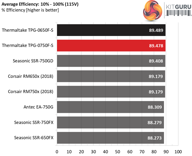
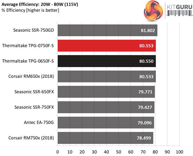
Efficiency Rating
The following graph shows the PSU's average efficiency throughout its operating range, with an ambient temperature close to 30°C.
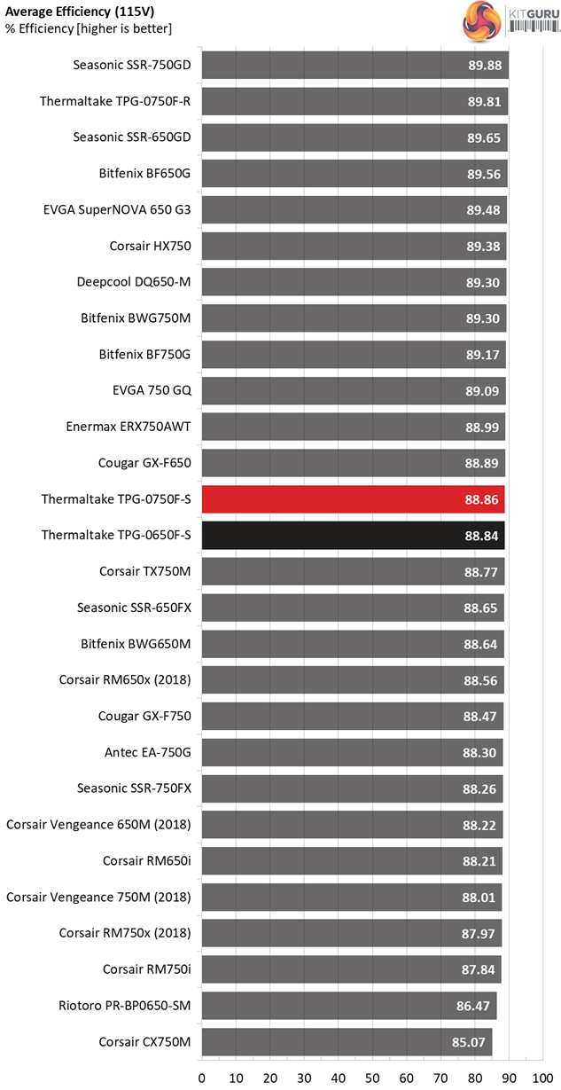
Almost the same overall efficiency for both units.
The Thermaltake Toughpower Grand RGB 750W Gold (RGB Sync Edition) retails for $110 in the US while in the UK market is sold for £127 (including VAT). That's a pretty dire conversion rate for UK enthusiast users.
This is a highly efficient and silent power supply with good ripple suppression, a HDB fan and Japanese caps. It also features RGB lighting, something that its major opponents (Corsair RM750x and Seasonic Focus Plus Gold 750W) lack.
The big question here is whether all above positive aspects of this product are enough to put it on top of your buying list. In my expert option I don't think so, and let me explain why.
The load regulation is loose, the transient response is mediocre on all rails and the inrush currents go through the roof once you attempt to power up the unit with its bulk cap discharged. Moreover, I don't feel so confident about the quality of the Chinese FETs used in the primary side. On the other hand, Thermaltake looks to trust those parts else it wouldn't provide a hefty ten-year warranty to this product.
If you are desperately seeking for a PSU that has RGB lighting and you also want to be able to control this feature through software, then your choices are limited and you should include a Thermaltake product in your list, since this brand is the leader when it comes to RGB-lit power supplies.
The rest of the major brands don't seem to bother so much about RGB lighting, since they give priority to performance. In my book this is the right thing to do, since in a power supply performance should be the key selling point. That said, there are still users who want a cool looking power supply and since in the market the people's desires prevail, I cannot persuade them to focus first on performance over fancy RGB lights.
All in all, this unit achieves decent performance, however with the same amount of money someone can get a notably better model and on top of that Thermaltake only provided a single EPS connector, so if you want to power a Threadripper system or a high-end mainboard that needs more power in the CPU area, then this is not a suitable unit.
In my opinion no power supply with 750W and more max power should come with a single EPS and it would be nice if the high-end 650W models also provided the capability for two EPS connectors.
Which are the changes/improvements that I would like to see in a future version of this platform?
- Lower inrush currents.
- Two EPS connectors.
- The EPS and PCIe sockets to be electrically compatible or different.
- Tighter load regulation (within 1% on all rails).
- Improved transient response.
- Longer hold-up time by 1-2 ms.
- Lower EMI at below 1MHz frequencies.
- Lower power consumption in standby.
- Infineon or equal quality FETs in the APFC converter and as primary switching FETs.
Here is the lists of the Pros and Cons for the Thermaltake Toughpower Grand RGB 750W Gold (RGB Sync Edition).
Pros:
- Delivered full power at 47°C.
- Efficient.
- Efficient 5VSB rail.
- Low ripple.
- Silent.
- RGB memory function.
- RGB lighting can be controlled either manually or through compatible software (with all popular brands being supported)
- HDB fan.
- Adequate clearance between the peripheral connectors.
- 10-year warranty.
Cons:
- Single EPS connector.
- The EPS and PCIe sockets are identical, with those cables being electrically incompatible
- Loose load regulation on all rails.
- Lousy transient response.
- High inrush currents.
- The hold-up time should be a bit longer (1-2 ms).
- Increased conducted EMI at lower frequencies (<1 MHz)
- Increased vampire power with 230V input.
Buy from SCAN computers in the United Kingdom HERE.
KitGuru says: The fresh ToughPower Grand RGB Gold has a distinctive appearance and RGB lighting features, but there are better performing supplies available such as the Corsair RM750x and the Seasonic SSR-750FX – at similar price points. Do you want a very high performance unit, or one that ships with RGB lights for a specific system build you are planning? We feel that this Thermaltake unit should only hit your final shortlist if you simply must have RGB lighting above all else.