

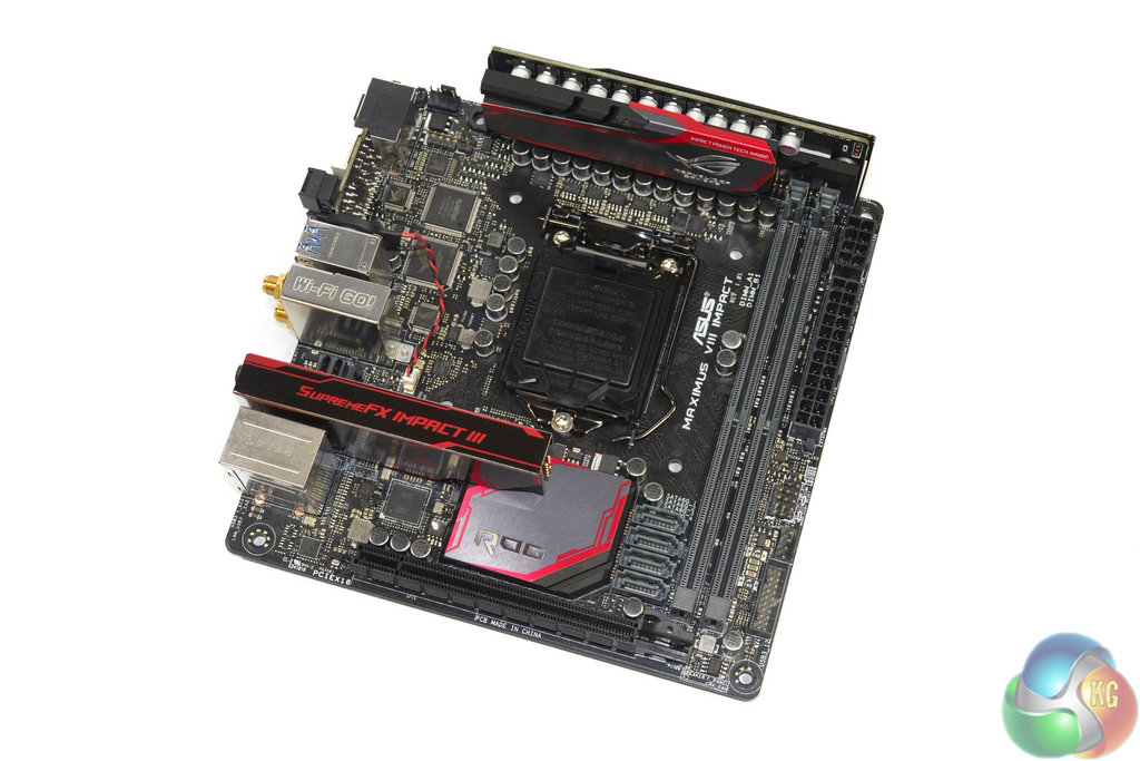
Styling-wise, the Asus Maximus VIII Impact follows a similar path to other ROG components. Subtle hints of red contrast the dark shades of black and grey to create an appearance that is easy to match with partnering hardware.
Two single-latch DIMM slots can be used to install up to 32GB of DDR4 memory in dual-channel mode. Asus advertises frequency support for up to 4133MHz DDR4 sticks, although such high speeds will also depend on other factors such as the BIOS revision and CPU's IMC strength.
Despite using single-latch DIMM slots, the opening latch is actually positioned near to where a long graphics card will sit. This has the potential to cause a slight difficulty when replacing the memory in a built system, however there is just enough room to avoid complete interference with a graphics card's PCB.
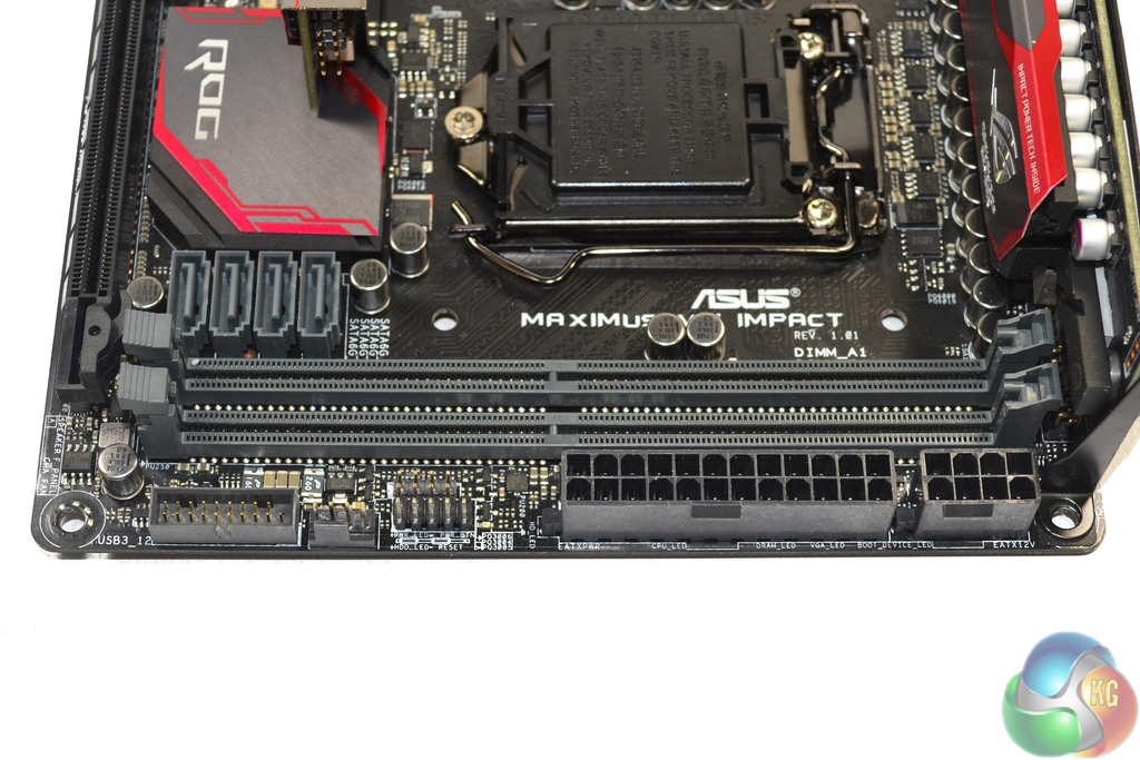
Asus positions both the 24-pin and 8-pin power connectors on the board's right edge. This has the potential to make cable management a little trickier as two physically large cables will have to be routed to the same location. With that said, looking at cases such as Silverstone's excellent SG13, the positioning can also give greater accessibility to the power connectors.
Adjacent to the power connectors are the front panel chassis headers and a 4-pin chassis fan connection. The lone internal 5Gbps USB 3.0 header receives its ports directly from the Z170 chipset.
While in the area of the DIMM slots, it's worth pointing out that we suffered the error code 55 issue that seems to be common for Asus' Maximus VIII motherboards. After wasting time (unsuccessfully) trying to get the system to POST with 3200MHz XMP enabled, reseating the CPU and switching to the other two DIMMs in our four-stick set solved the issue.
It's disappointing to see stability issues persisting this long after the Z170 platform's introduction. That statement is especially true when one factors in the solid track record that Asus has for releasing stable motherboards with bug-free BIOS implementations.
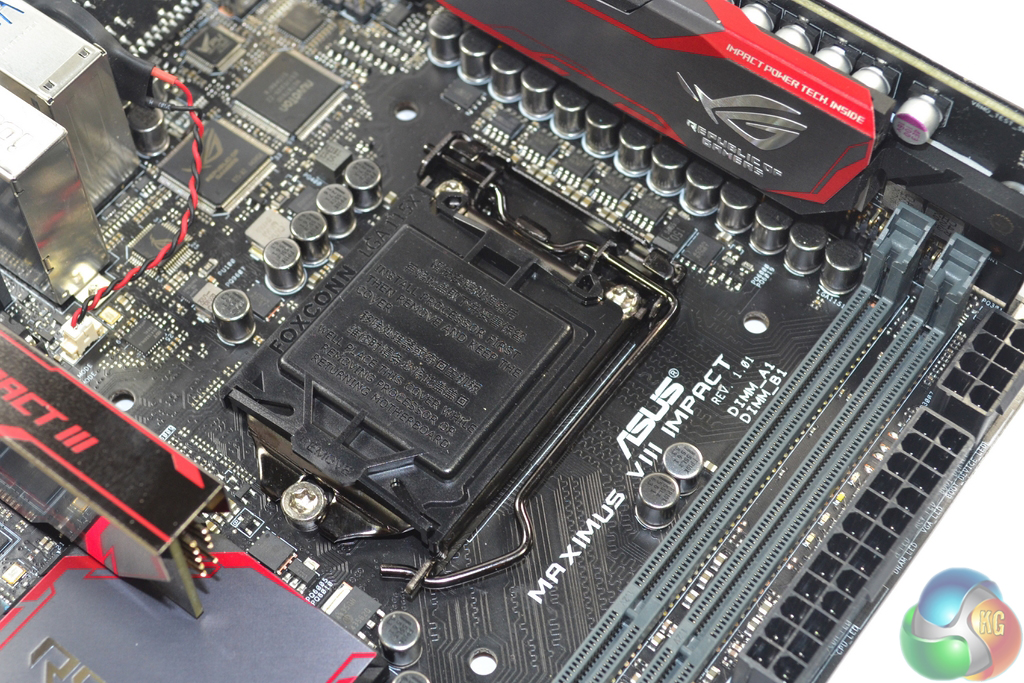
Support for Intel's LGA 1151 line-up allows the Maximus VIII Impact to form the foundation of a high-performance gaming system. The included installation tool can aid users who are less familiar with the process of building an Intel-based system and don't want to risk damaging the socket pins.
Asus uses an IDT-designed clock generator to provide management for adjustment of the BCLK frequency. This is important to not only overclockers who are trying to squeeze every MHz out of their system, but also buyers who want to overclock Intel non-K CPUs. The Maximus VIII Impact does indeed (unofficially) support non-K CPU overclocking, however this requires a BIOS update and is not officially sanctioned by Intel.
The CPU socket area is relatively clear of interference mechanisms for CPU coolers typically found in mITX builds. AIO liquid cooling pump and waterblock units should fit without issues. However, some large top-down coolers will have to clear the heightened audio module and power board in order to be installed.
As a note, we managed to install a Noctua NH-D14 CPU cooler without any motherboard interference. Using a CPU cooler of such size is feasible if your chassis provides the appropriate clearance.
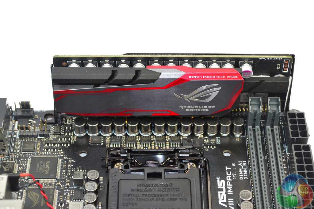
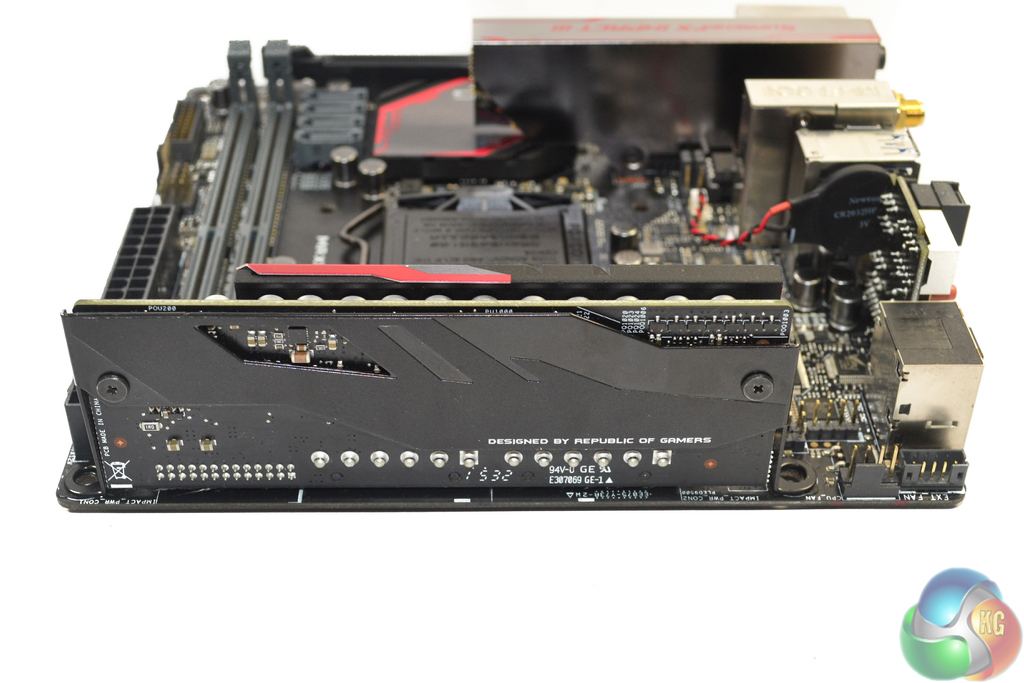
Finding the PCB real estate to deploy an enhanced power delivery system can be challenging given the mini-ITX space constraints. For a number of generations, Asus has overcome this challenge by deploying a dedicated power delivery board that uses a small amount of motherboard PCB space and increased height to house electronic components.
It's worth noting that the Impact Power III board's dimensions have been specifically designed to comply with the mini-ITX chassis standards.
Credit where credit is due, the vertical power board is one of those pieces of innovation that deserves all of the praise it gets. The design allows valuable PCB space on the motherboard to be freed up to house other components such as chipsets and connectivity slots.
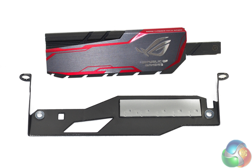
Asus takes the cooling of its Impact Power III board as seriously as enthusiast buyers would expect. A sturdy metal heatsink is used to cool the front-side MOSFETs, while a rear backplate provides stability to the vertical board and also cools additional controllers.
I like the design of the front-side VRM heatsink. The red, grey, and black colour scheme works well, which is a positive as the heatsink may be visible in certain system builds.
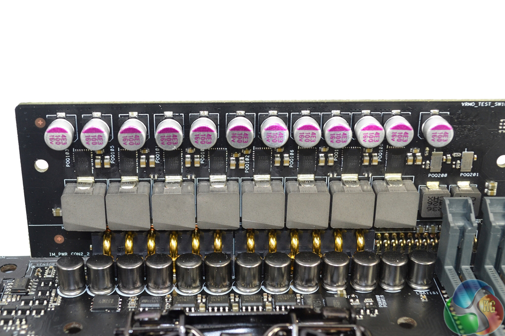
Asus uses a total of eight phases to feed the CPU and iGPU, as well as a further two phases for the memory. Central the power delivery system are eight of International Rectifiers' PowIRstage IR3553M MOSFET solutions. Delivering a 40A output per stage, the IR3553M solutions are smart choices for usage in a confined area thanks to their co-packaged design.
In addition to the MOSFET solutions are Asus' MicroFine Alloy chokes and 10K-rated capacitors. The chokes are touted to deliver higher efficiency and lower operating temperatures due to their smaller powder particle size. A pair of 25A Texas Instruments CSD87588N (marked 87588N) NextFET power blocks and two R36 chokes form the additional two power phases.
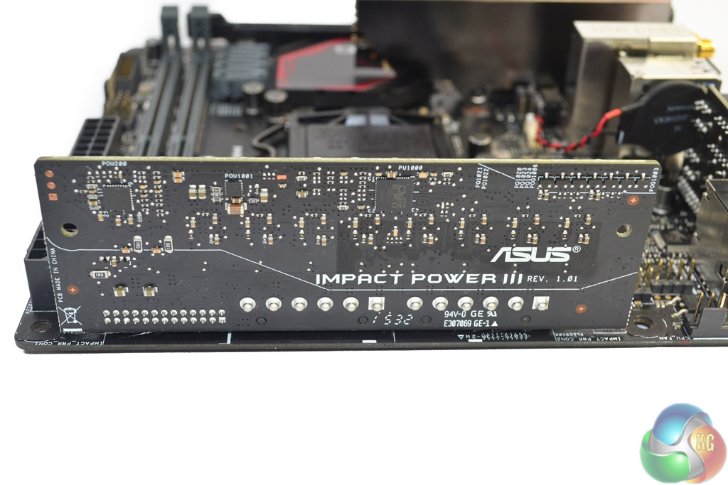
Control of the system is handled by Asus' Digi+ EPU ASP14051 and Digi+ ASP1103 controllers located on the power board's rear. Information relating to Asus' custom-branded PWM solutions is very difficult to obtain, however the ASP14051 controller seems to manage the CPU and iGPU phases while the ASP1103 chip manages the memory power.
A number of ON Semiconductors' NTMFS4C06N (marked 4C06N) single N-channel MOSFETs are scattered around the CPU socket and entry pins for the Impact Power III board, as are Anpec Electronics APL5337 linear regulators. There is also a chip labelled 7163 ONFK on the rear of the power board, however I could not detect its function.
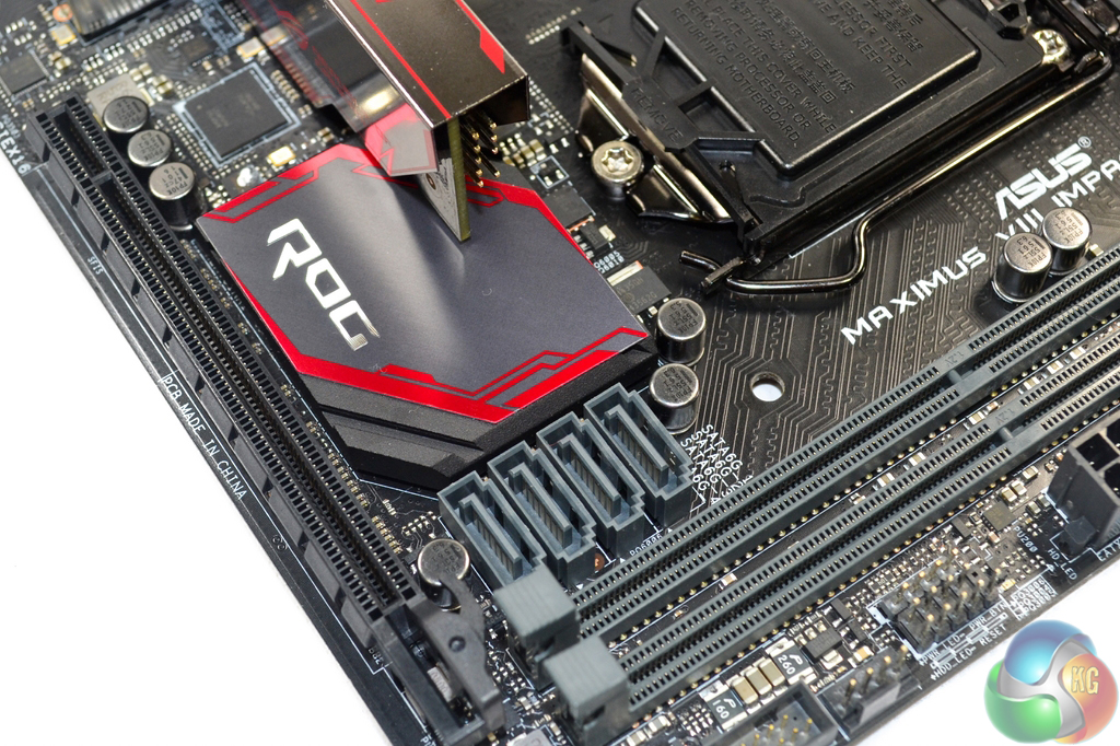
Asus only includes four SATA 6Gbps for the Maximus VIII Impact, which seems meagre given the Z170 chipset's healthy set of IO lanes and flexibility. Two RAID-0 boot SATA SSDs alongside a single storage HDD and an optical drive is not such an outrageous configuration for mini-ITX enthusiasts, however it is one that saturates this board's SATA expansion options.
I strongly believe that Asus should have included a single SATA-Express connector on the Maximus VIII Impact. This would have the benefit of providing two additional SATA 6Gbps ports, which would be useful for many enthusiasts. Alternatively, users could have connected a front panel USB 3.1 bay to the SATA-Express port. As it stands, front USB 3.1 support for the Maximus VIII Impact seems borderline impossible (other than routing a cable from the rear IO).
The SATA ports' outwards-facing orientation may not be ideal for cable management, however it is a necessity on a mini-ITX motherboard due to chassis space constraints and interference potentials.
A single PCIe 3.0 x16 slot provides expansion capabilities. Asus routes all of the LGA1151 CPU's sixteen PCIe 3.0 lanes to the full-length slot, allowing a gaming graphics card to receive unrestricted bandwidth. The slot's retention lever is repositioned to provide easier access with a graphics card installed.
Adding to the somewhat limited storage options for Asus' board is the omission of an M.2 connector (!). This is completely unacceptable. The connector could have been positioned on the rear of the board, or even in a vertical or sideways orientation (albeit with potential interference or cooling issues).
And there's no argument for a lack of connectivity – the bandwidth could have been shared with the U.2 slot, a minor rearrangement of chipset resources would provide a PCIe 3.0 x4 connection, or Asus could even dive into the CPU's 16 PCIe lanes for the M.2 slot, as they did with the Z97 Maximus VII Impact. Asus will argue that the 32Gbps PCIe 3.0 x4 U.2 connector is a viable alternative to an M.2 slot, and that will probably be true in one or two years' time.
But as of right now, the M.2 slot is far more useful than onboard U.2 connectivity. The only viable U.2 SSD for consumers is Intel's SSD 750 drive in the 2.5″ form factor. Conversely, there are more M.2 SSDs on the market than I care to count, including numerous PCIe 3.0 x4 and NVMe drives from the likes of Samsung and more on the way from vendors such as Kingston and Plextor. M.2 to U.2 adapters are commonplace too.
How Asus' engineers decided that it was a good idea to release a high-end mini-ITX Z170 motherboard without an M.2 slot is completely beyond me. You can't even use the PCIe x16 slot to house an M.2 SSD via an adapter card as that dictates the removal of one's gaming graphics card. This decision has the potential to completely alienate a large proportion of potential buyers.
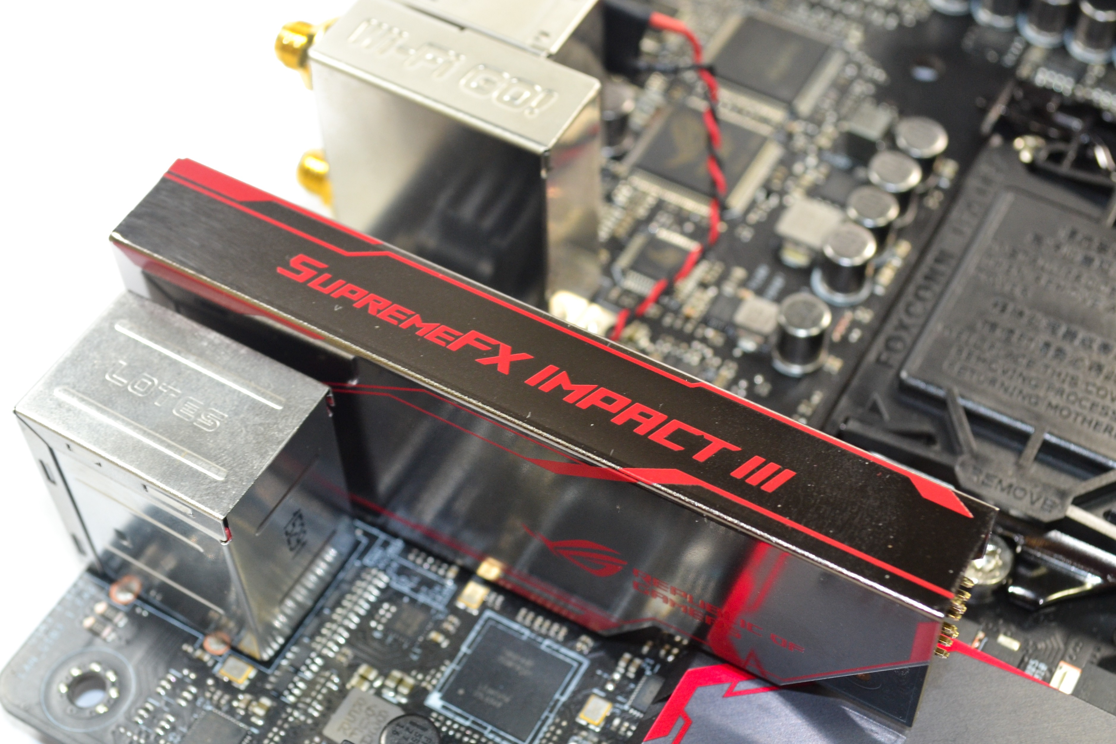
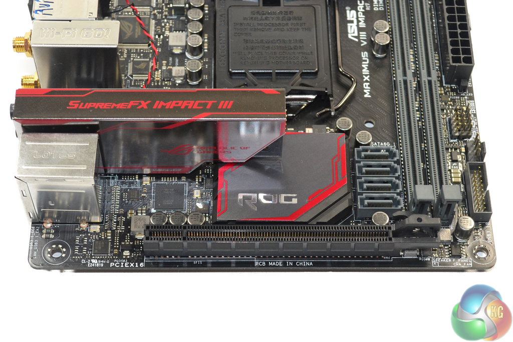
Asus' SupremeFX Impact III audio solution is based around the Realtek ALC1150 audio codec and housed on a dedicated daughter board. An ESS ES9023P DAC is found alongside a Texas Instruments RC4580 op-amp, a dedicated SonicSense amp, and a NEC-built de-pop relay (possibly the UD2-4 5NU, although I cannot confirm).
In addition to the audio hardware is a dedicated clock and multiple Nichicon audio capacitors. EMI prevention methods include shielding of the audio board and segregated PCB tracks. The front-panel audio header is located directly on the SupremeFX Impact III board. Users of high-end surround sound speakers will be disappointed by the inclusion of only three rear panel audio jacks.
To compliment that audio hardware, Asus provides a comprehensive software tool to give audio control to the motherboard’s users.
Just beneath the audio board are Asus' Probelt onboard voltage monitoring points. Usage of these measurement tools requires removal of the audio board, however this is unlikely to concern hardened overclocking users. In close proximity are the noteworthy LN2 and Slow mode jumpers which will prove beneficial for competitive overclockers.
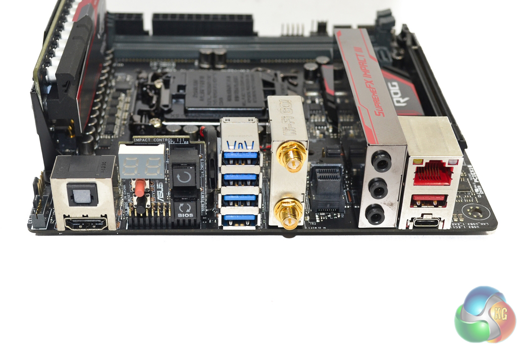
Sat in an internal section, near to the rear IO ports, is the motherboard's 32Gbps PCIe 3.0 x4 U.2 connector. This outwards facing port can be used to provide connectivity to the likes of Intel's 2.5″ version of the 750 series NVMe SSD. Availability of U.2 devices is currently limited, however it is expected to grow significantly in the coming years.
SPDIF optical audio out and an HDMI 1.4b port are found on the rear IO. The HDMI port does not support UHD 4K resolutions with a 60Hz refresh rate, and as such I would have liked to see Asus include a 4K60P-capable DisplayPort output on the same vertical stack as the media-centric HDMI connector.
All four of the 5.0Gbps USB 3.0 ports operate from the Z170 chipset. I would have liked to see a pair of USB 2.0 ports and a PS/2 keyboard/mouse connector placed on the rear IO for peripheral connectivity and troubleshooting convenience (which overclockers would welcome). The U.2 connector unnecessarily takes space away from the rear IO ports and should be repositioned. As it stands, there is absolutely no USB 2.0 connectivity on this board at all (not even an internal header).
Two gold-plated antenna connections for the two-stream, dual-band 802.11ac WiFi are visible on the rear IO. The Qualcomm Atheros QCA61x4A MU-MIMO wireless card is capable of transfer rates of up to 867Mbps and can operate at lower speeds on the 2.4GHz frequency band. Bluetooth 4.1 is also provided.
Intel's I219-V chipset provides Gigabit Ethernet to a jack that features Asus' LANGuard protection design. Asus' own GameFirst software provides network management in a similar fashion to Killer's Network Manager software. One cool feature of the GameFirst IV software is Multi-Gate Teaming, which allows network connections to be combined for greater bandwidth and potentially smoother gaming.
10Gbps USB 3.1 Type-A and Type-C ports are provided by Intel's formerly-Alpine Ridge DSL6540 controller. The chipset's ability to use four PCIe 3.0 lanes for a total bandwidth of 32Gbps is one of the reasons for its preference over ASMedia's ASM1142 alternative, which is potentially bandwidth limited. EtronTech EJ179V and EJ179S ICs are installed on the board, with the former providing the USB 3.1 Type-C form factor.
Asus' Impact Control board is an excellent addition which gives overclockers and general users onboard buttons and access to troubleshooting error codes. The power, reset, clear CMOS, and BIOS Flashback buttons are all likely to be useful at some point. Positioning of the control board is also smart, as LN2 overclockers will not have to worry about the buttons freezing over.
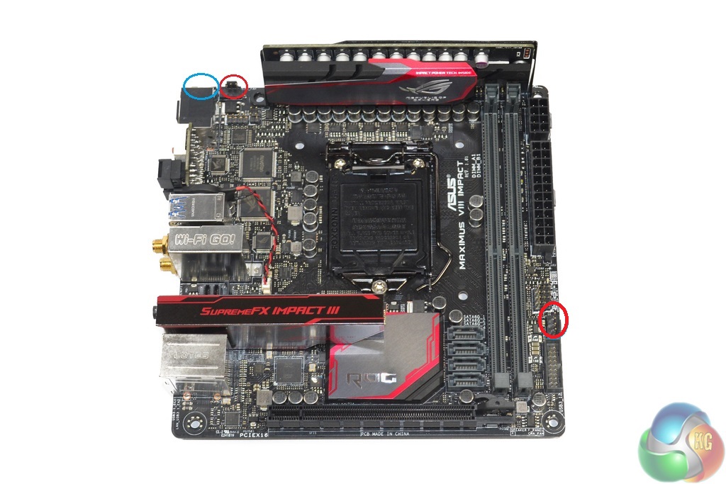
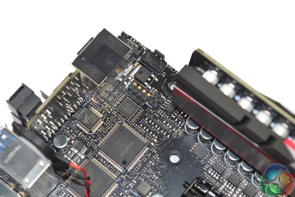
Two 4-pin fan headers are found on the motherboard. The number of headers can increase to five when using the fan extension card which connects via the blue circled 5-pin header. There is also a single 2-pin temperature header located close to the upper-left 4-pin fan header.
UEFI and software control of all of these fan headers is superb. Nuvoton's NCT6793D chipset is in charge of fan control and system monitoring for the motherboard, while an additional Nuvoton NCT7802Y chipset manages the fan extension card connections.
A TPU KB3720QF chip handles Asus' automated overclocking tuning, while additional ROG-branded chips manage other functions such as KeyBot.

Looks like a great ITX board but no m.2 = no purchase from me 🙁
No M.2 = no purchase.
I have the z170i Pro Gaming, which has a lot of these features (but has M.2 NVMe), minus the additional soundcard and VRM cooling (but still has decent of both) and can go as high as 4GHz on the RAM (though my BIOs shows 4.133Mhz). Same Software, same Wifi… about £50 cheaper.
That said, I’m in the process of returning it to Scan as the WiFi died on me. Let me just say that Scan have a horrendous returns policy. No advanced return. Offered to just buy a new board and they refund me when they received mine… they said ok, but were only willing to refund £125 (the price I paid). It’s now £133 + £12 postage on their website, so I’d be out of pocket. So, I have to wait 5-7 days to return. Moral of the story – buy from Amazon (sold and fufilled by) Free next day delivery for Prime and they ship a replace before you return.
EDIT:
Those VRMs would interfere with most cooling in ITX cases too. At least in my Corsair Obsidian 250D, which is a squeeze with my H100i GTX as it is.
there are u2 to m2 converters… and as someone who has the Intel 750 SSD, this board was exactly what i needed.
A few days ago new McLaren F1 subsequent after earning 18,512$,,,this was my previous month’s paycheck ,and-a little over, 17k$ Last month ..3-5 h/r of work a day ..with extra open doors & weekly paychecks.. it’s realy the easiest work I have ever Do. I Joined This 7 months ago and now making over 87$, p/h.Learn More right Here
as…..
➤➤
➤➤➤ http://GlobalSuperEmploymentVacanciesReportsNet/GetPaid/98$hourly…❦.❦.❦.❦.❦.❦.❦.❦.❦.❦.❦.❦.❦.❦.❦.❦.❦.❦.❦.❦.❦.❦.❦.❦.❦.❦.❦.❦.❦.❦.❦.❦.❦.❦.❦.❦.❦.❦
Do you have a link for U.2 to M.2 adapters? I have seen M.2 to U.2 but have yet to come across the other way around.
Indeed USB 2.0 devices will work fine in USB 3.0 ports, however the lack of an internal header could be a problem to somebody who has a mini-ITX chassis with front panel USB ports, in addition to something like a card reader. There’s not enough internal USB (including 2.0, which is small and easy to fit on the PCB) connectivity in that case.
Yes, there are quite a few enthusiast mini-ITX cases (Corsair 250D, Phanteks Enthoo ITX, etc.) that will take four SATA devices or more. And that’s without just placing 2.5″ SSDs in some free space, without an actual drive mount (which is quite common and perfectly fine). Some people will want more than 4 SATA devices, especially with the lack of M.2, so it would have been better to include another two SATA ports (especially because the Z170 chipset has plenty of spare lanes). If 4 SATA ports is fine for somebody’s needs, then great – that point is not an issue at all.
Which CPU cooler are you using? The NH-D14 fit fine in our testing. Make sure to send some pics to our Facebook page when you’ve completed the build :)!
i dont understand why so many insist on a PS/2 keyboard/mouse connector. This is a High end board. Thus majority will have New-ish USB keyboard mouses? why waste the space. Get real Kitguru. Your spending a solid Few hundred on a Motherboard, your going to have a decent mouse/keyboard combo too.
If the U.2 port is positioned under the board like my Z170i Pro Gaming then an adapter might be an issue…
Showing my ignorance, though, as I’m unfamiliar with U.2. The bus link is the same PCI-E x4, though, so I don’t see the advantage on this board. Surely a topside M.2 with a U.2 adapter would be the best case scenario?
I wouldn’t say the Z170 has spare lanes. SLI/XFire is more limited than the 2011-3 X99 boards due to less lanes on the CPU
When I say Z170, it refers specifically to the chipset, not the LGA 1151 CPU or the platform as a whole. The CPU’s lanes are generally reserved for the wider PCIe links (x4, x8, x16) for graphics and other expansion cards, however that’s not really important with this board as all 16 lanes get delivered straight to the one full-length PCIe slot.
The Z170 chipset has spare lanes available for use, compared to what has been deployed on this motherboard. The Z170 chipset itself actually supports up to 26 IO lanes, however there are some limitations as to how many of these can be deployed as PCIe, USB, and SATA 6Gbps.
I think youre right, I cant find a link, must have been thinking of M.2 to U.2, once there is a market for it im sure adapters will exist though.
Like a said, for my use case all of the above are non issues.
I am going to be putting a build together in the RVZ02 and trying either the Scythe BIG Shuriken 2 Rev. B or the Zalman low profile. Not sure yet, Im overseas and the mobo is stuck in customs.
yeah max lanes for m.2 is the same as u.2, but if im not mistaken some of the boards that have m.2 and more additional connectivity options share some of the lanes? Like depending on your configuration and what you are using, your m.2 is limited?
if the u.2 was am m.2 instead, would one of the converter cards fit in there?
Yeah, sure, but X99 boards can support x16, x16 and x8 configurations on PCI-E with some spare for I/O… Just saying the z170 is lacking in the PCIE lanes department
Using this board in a HTPC build with a ML07 case and a gtx 1060sc gpu Ive run into an issue with the sound card connector for the front panel jacks,,it appears most low profile coolers end up right up against the sound card, leaving no room to connect the HD audio cable for the front jacks, if there was a cable that would allow the sound card to be mounted off the board somewhere it would help but I havent found a cable yet that would allow one to mount it elsewhere much like the included fan header card. As it stands now I will just cover the male connectors with insulating tape to keep them from contacting the cooler fins on my Geminii M4 cooler and forego using the front jacks until i get a different cooler or find a jumper cable that allows moving the sound card to a better mounting position in the silverstone case.