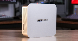

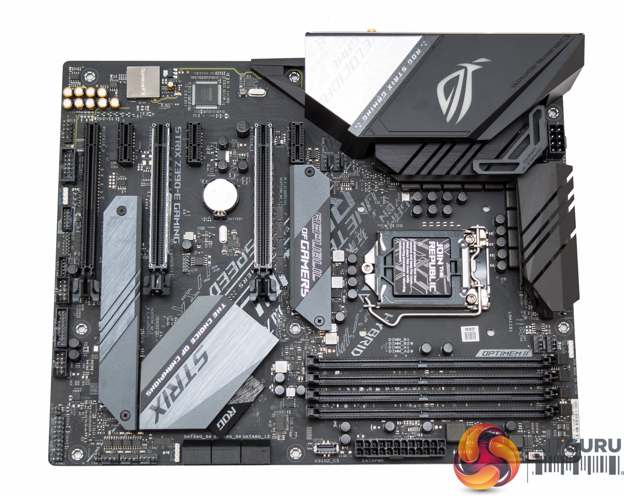
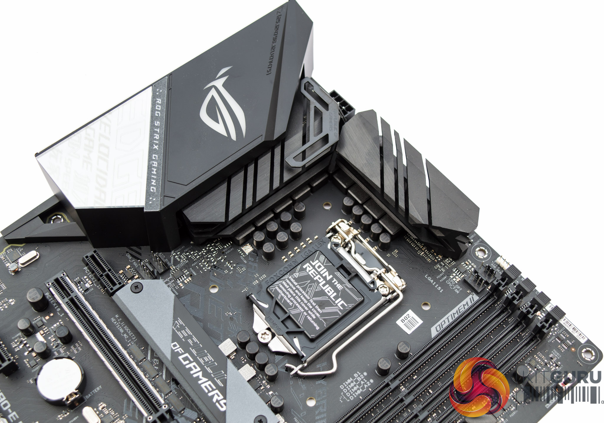
While the previous generation ASUS ROG Strix Z370-E Gaming went for a silver and off-white colour scheme, the new ASUS ROG Strix Z390-E Gaming is primarily black with some grey and silver accenting. The grey-ish accenting on the PCB of the Z370 model is gone and in its place is some “of questionable taste” writing on the central section of the PCB.
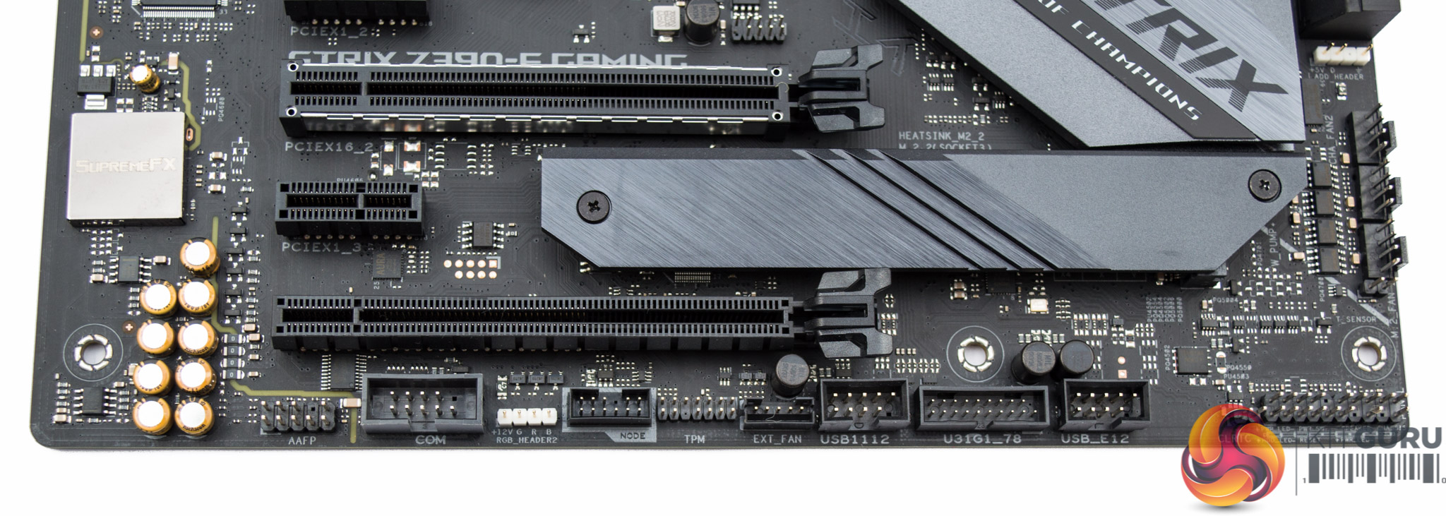
There is a single onboard RGB lighting zone which sits inside the rear I/O cover. Any additional RGB lighting connectivity has to be provisioned using the three onboard RGB headers. There is one 12v G R B header after the last PCIe lane (unshielded), one 12v G R B header next to the SATA port block and one 5v Digital header next to the CPU fan headers.
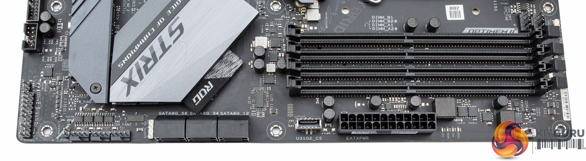
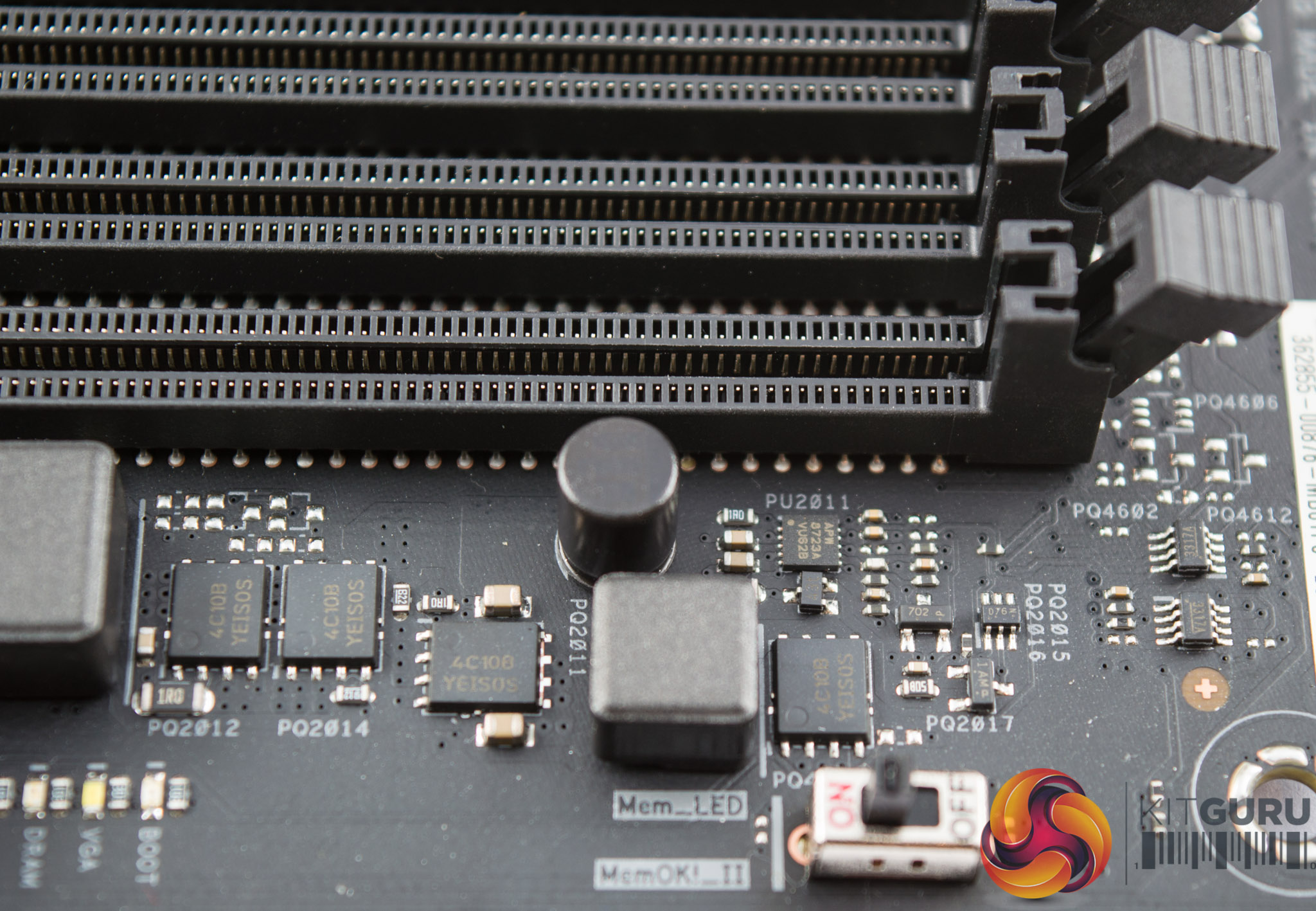
ASUS provides three fan headers in a row next to the block of six SATA ports. The USB 3.1 front panel header is located in between the SATA ports and 24 pin. In terms of diagnostics there is a MemOK switch and diagnostic LEDs available next to the 24 pin connection.
The lower section of the motherboard contains most USB connectivity as well as a 12v RGB header, the second 12v RGB header was next to the SATA block.
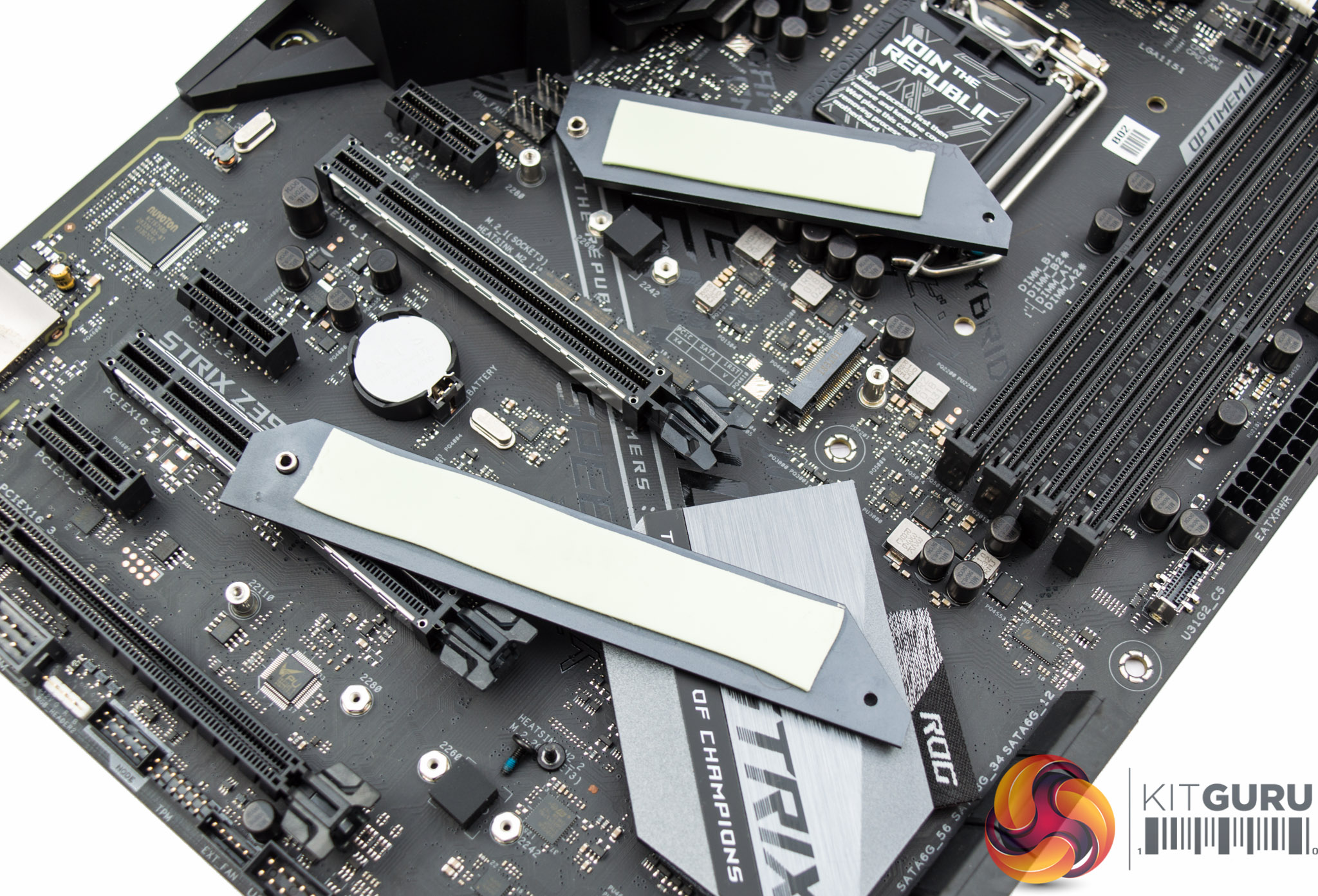
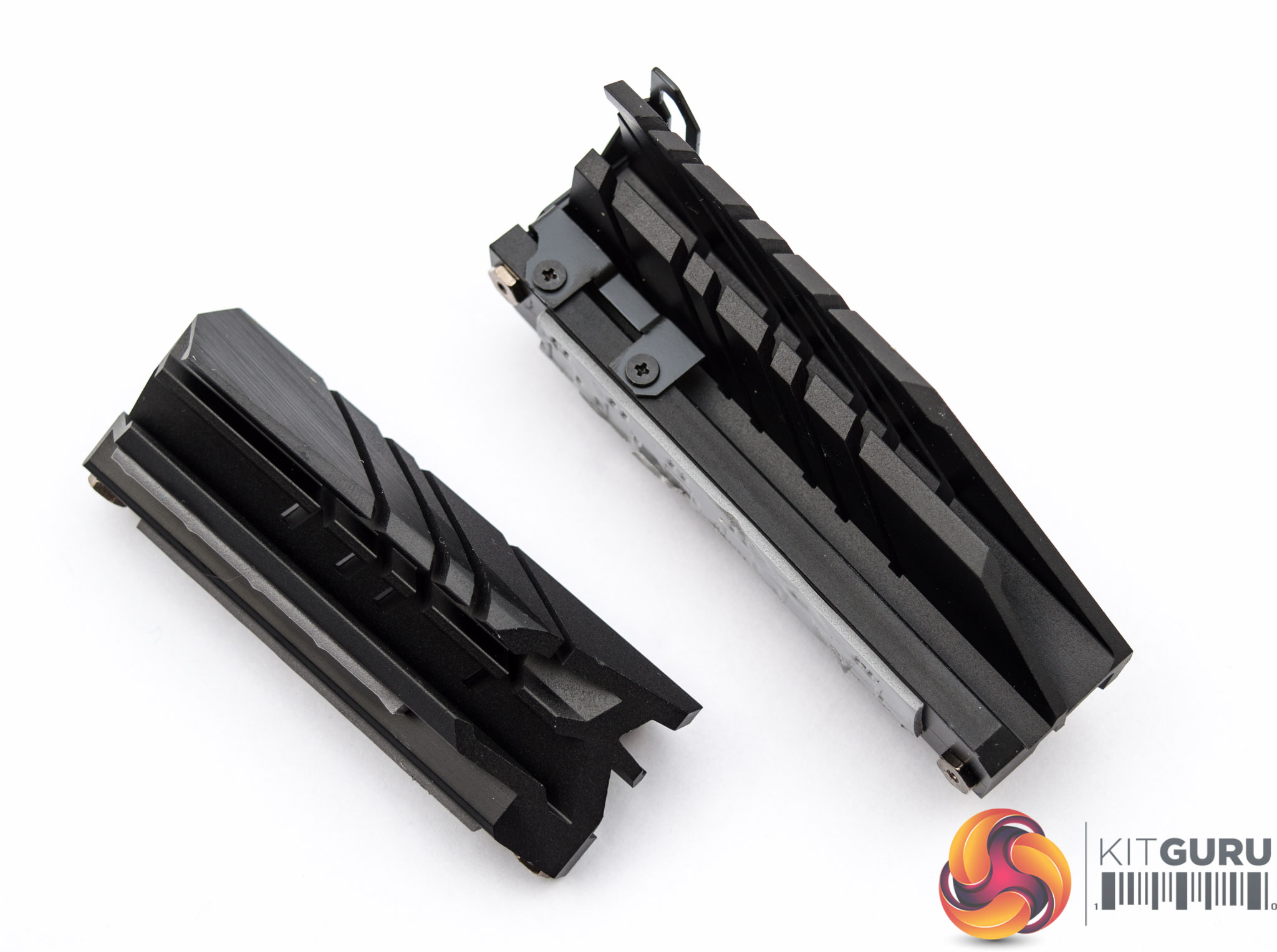
ASUS provide cooling heatsinks for both M.2 slots and both are purpose-built to fit the maximum length of each respective slot.
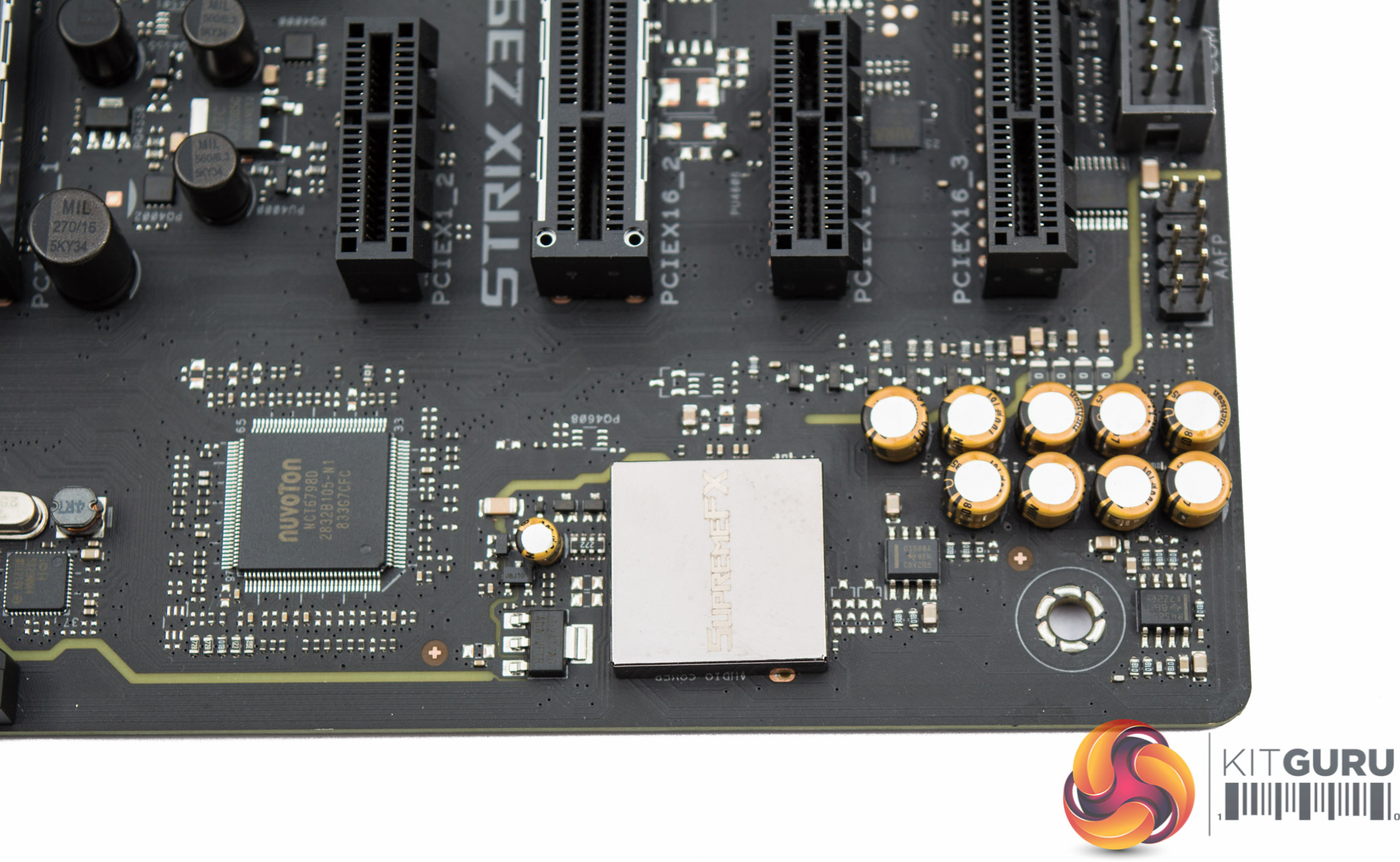
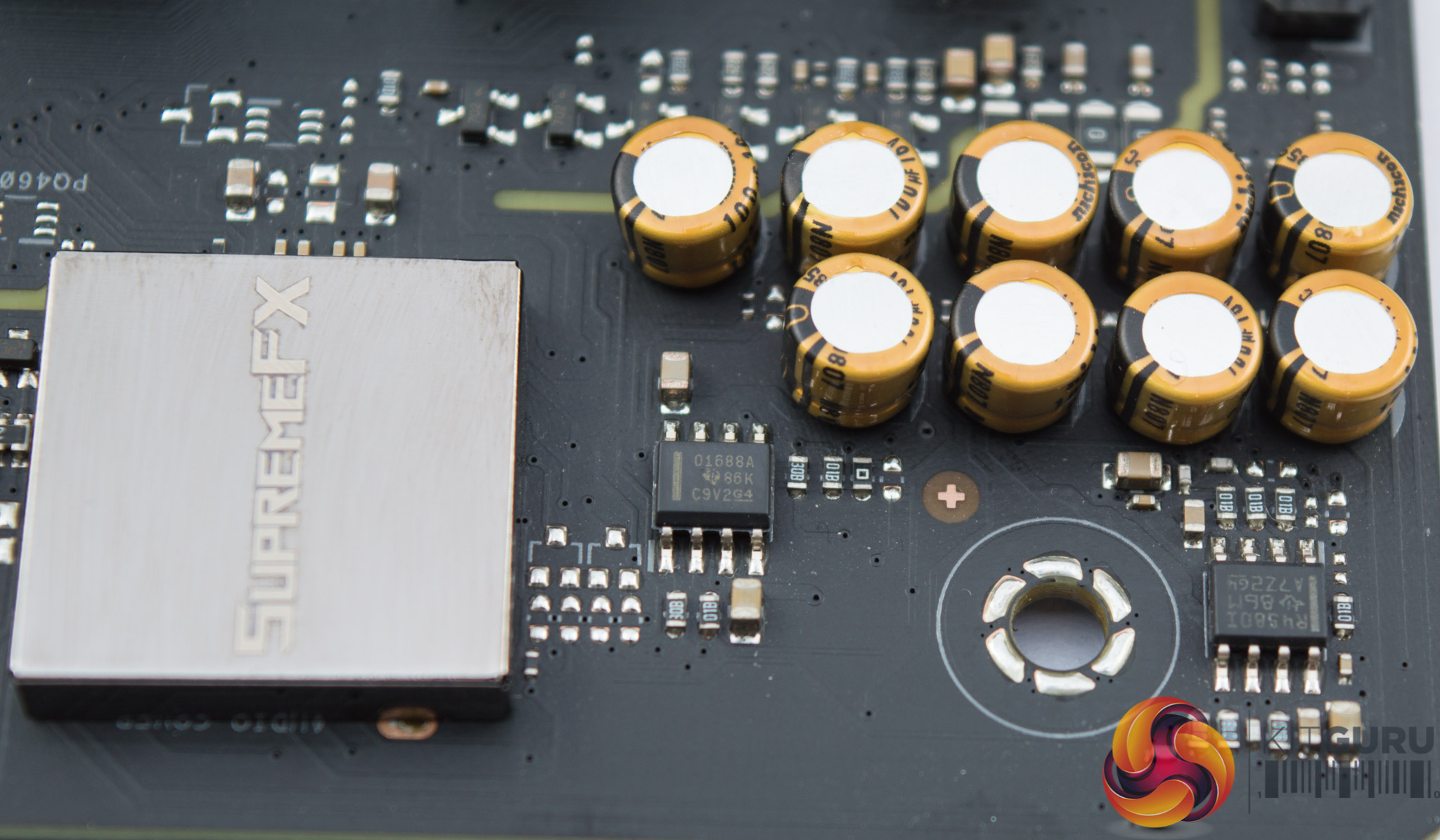
Audio is provided by a shielded Realtek ALC1220 codec within the SupremeFX package. There's dual operational amplifiers – Texas Instruments O(PA)1688A and RC4580(I) – alongside Nichicon Gold Series audio capacitors.
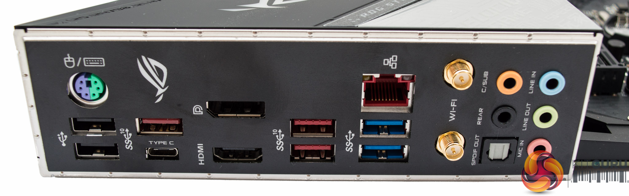
The rear I/O provides the following ports:
- 1 x DisplayPort 1.4
- 1 x HDMI 1.4b
- 1 x LAN (RJ45) port(s)
- 4 x USB 3.1 (3 x Type-A+1 x USB Type-C)
- 2 x USB 3.0
- 2 x USB 2.0
- 1 x Optical S/PDIF out
- 5 x Audio jack(s)
- 1 x ASUS Wi-Fi Module
The overall connectivity is good blend of “old” and new, with ample USB, display and sound options. Networking is somewhat average given many motherboards of this price segment are equipping dual Gigabit, but in practice dual-gigabit may not be that useful for most buyers.
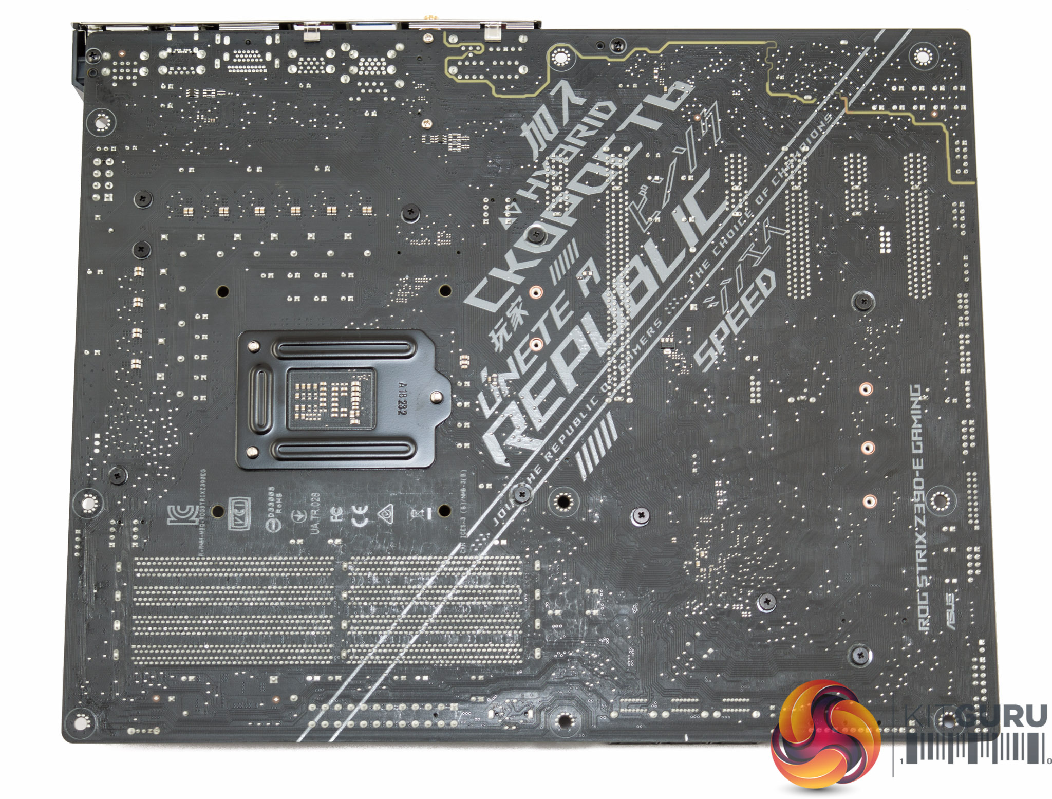
The underside of the motherboard shows only cross-head screws, good for maintenance and modification, while there are no doublers visible underneath the VRM area.
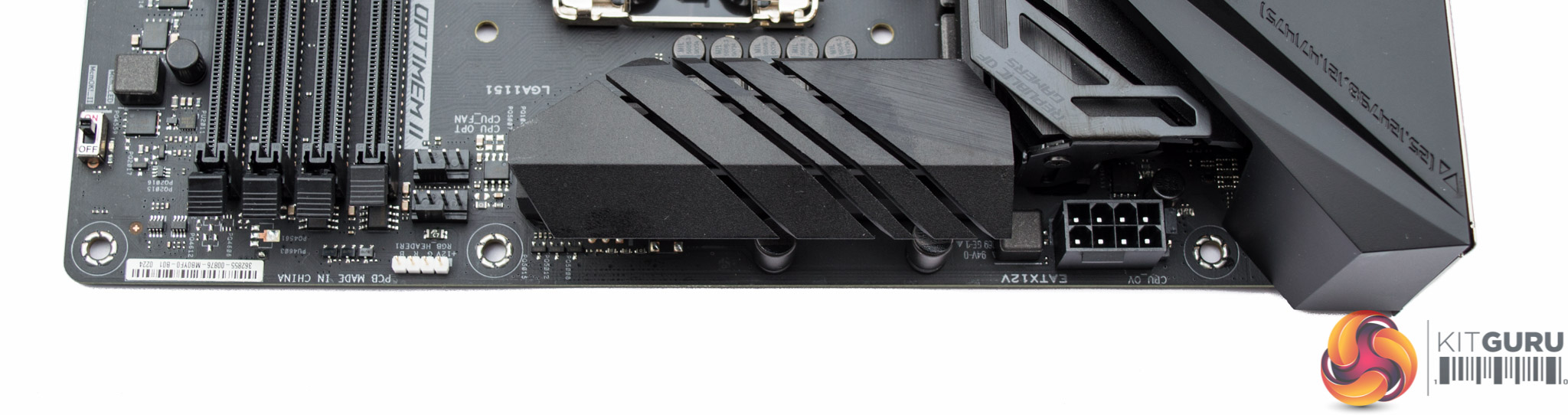
The CPU socket has two independent aluminium heatsinks to cool the VRM while power input is provided through a single 8 pin EPS. The bracket on the rear-most heatsink is to mount the optional 40mm fan provided in the accessory bundle. This would provide additional airflow to the VRMs, particularly important if engaging in high-voltage overclocking.
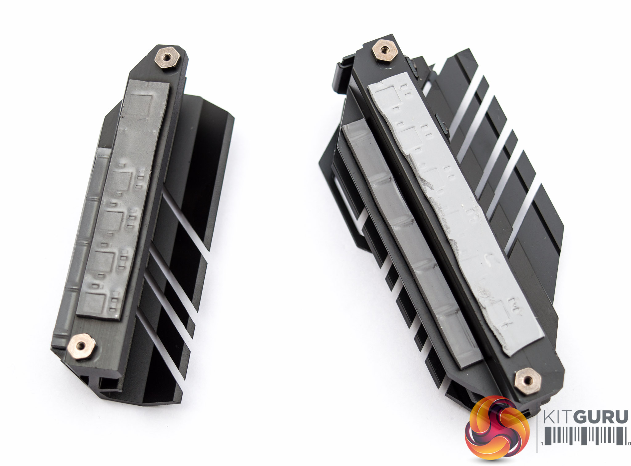
These two heatsinks are single aluminium blocks with thermal pads on the upper and lower segments to cool the inductors and MOSFETs respectively.
There is no heatpipe in either heatsink so the cooling solution is modest by any means, but the optional fan would help greatly in high-voltage overclocking scenarios.
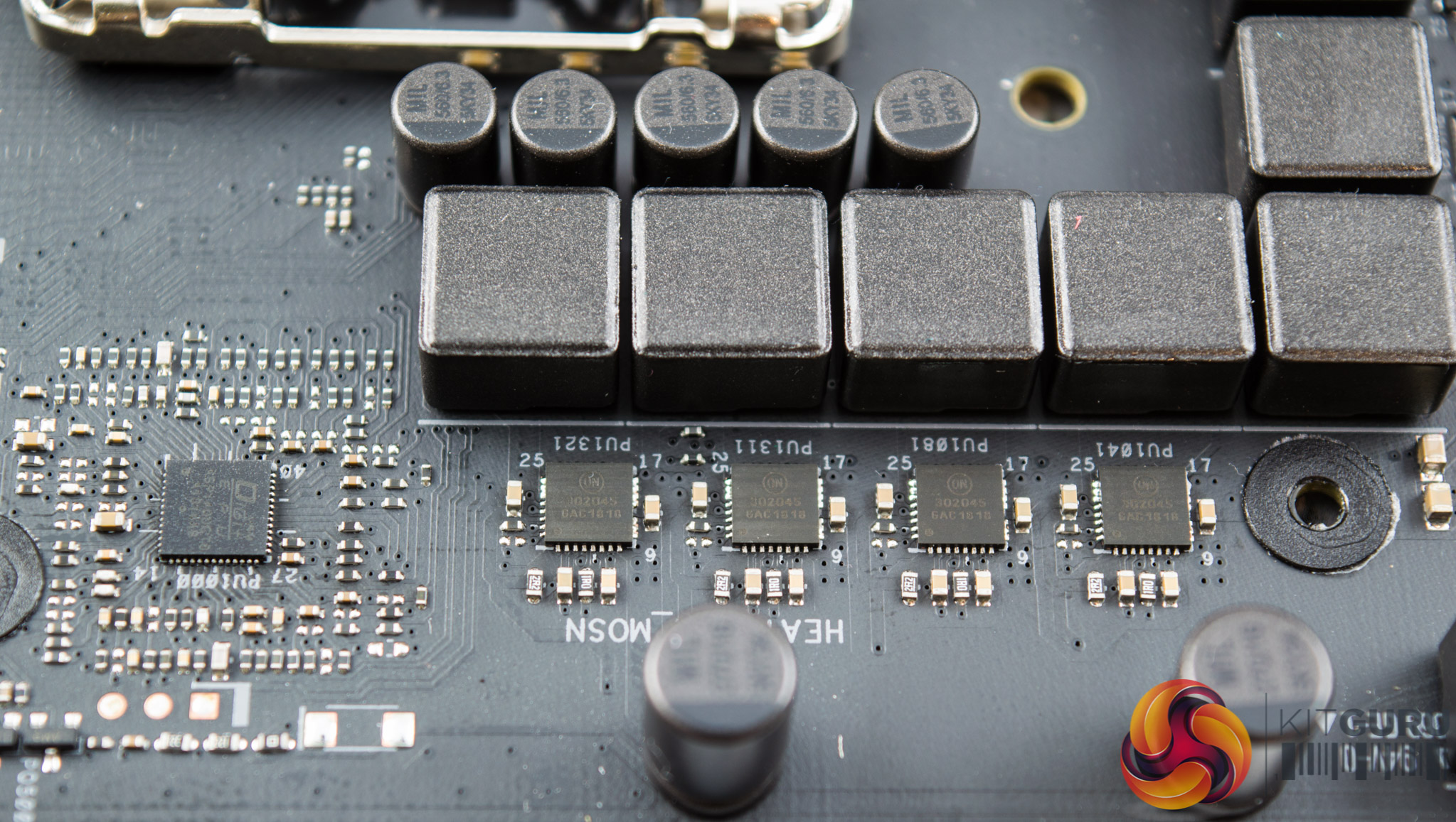
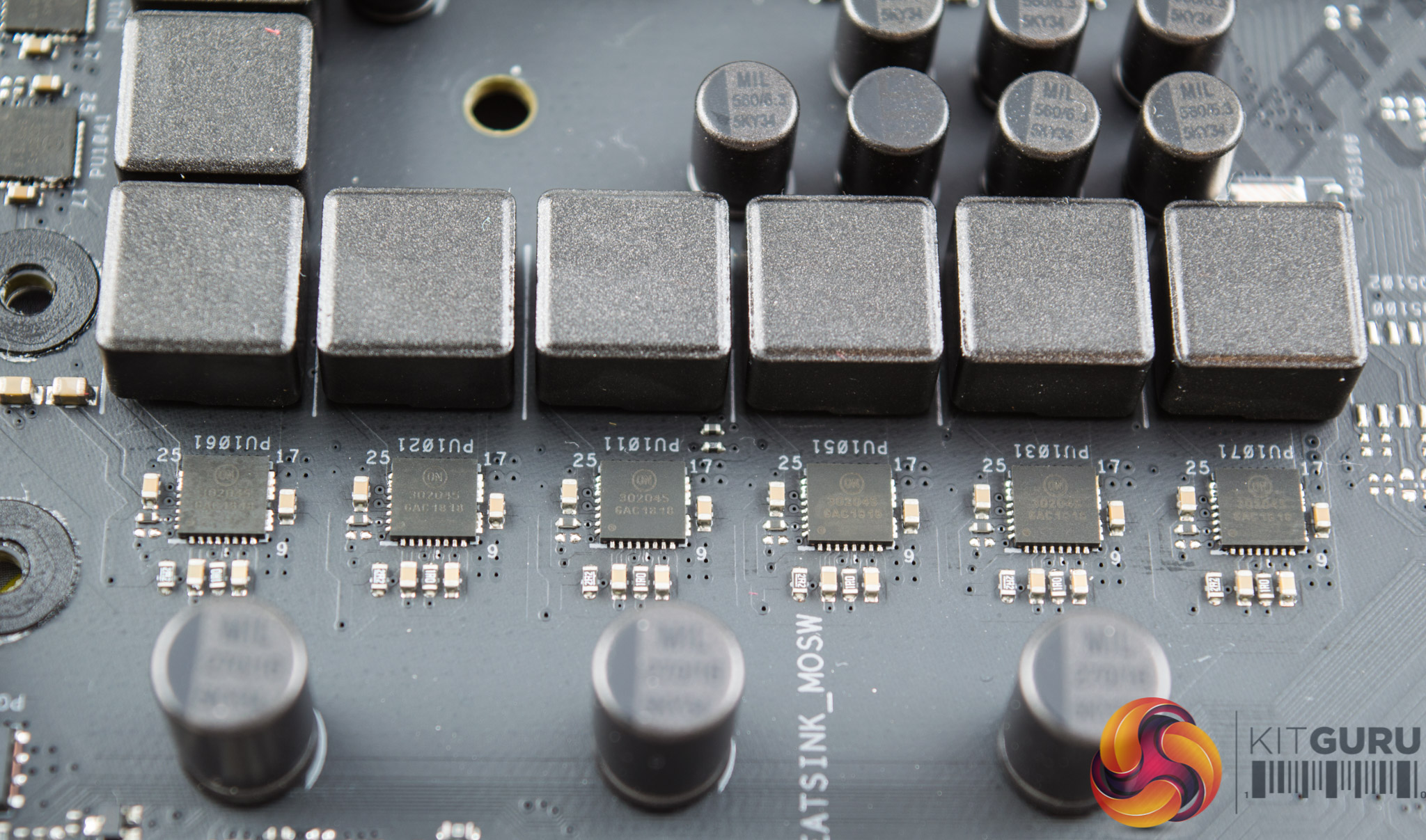
ASUS uses the same ON Semiconductor NCP302045 MOSFET package for every “phase”. This package integrates the high-side and low-side MOSFETs along with a MOSFET driver, it has an average current rating of 45-amps with a 75A peak.
The inductors are unmarked but are identical for all 10 MOSFETs and the Capacitors are marked “MIL 560/6.3 5KY34”, meaning the capacitors are 560uF and 6.3v units. ASUS claim, for both the MOSFETs and Inductors, “Superior chokes [inductors] and durable capacitors are engineered to resist extreme temperatures and provide up to 110% better performance than the industry standard.“
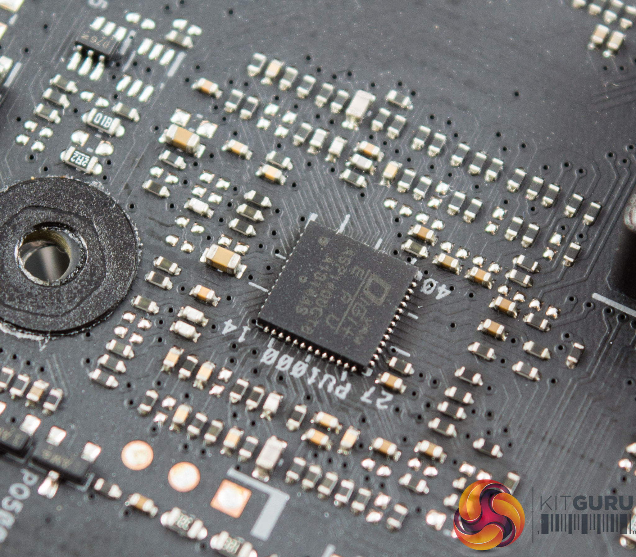
The PWM controller is marked ASP1400CTB and is a custom-packaged PWM controller for the “ASUS DIGI+ EPU”. It appears to have 53pins (14+13+13+13) which is less than an International Rectifier IR35201 (56pins) and more than an IR35203 (48pins). It's not clear if that means the controller is definitely not one of those units, or is a modified version of them specifically for use by ASUS.
One thing that does stand out is that ASUS has used this PWM controller on low-end motherboards in the past such as the ASUS ROG Strix H370-F Gaming and some B360 models. On the H370-F this controller was used with International Rectifier doublers which lends credence to the suggestion these are rebranded International Rectifier controllers.
To our knowledge this CPU PWM controller operates in a 4+2 phase mode with 2 MOSFETs, Inductors and drivers per VCore phase, with single components for the iGPU phases. That is 8 phases worth of components for the 4 VCore phases and then 2 “normal” phases for the iGPU phases. Even so, there appears to be no definitive proof that the 2 iGPU phases are not the same as the VCore phase – one PWM phase with twice the components of a normal phase.
As we've discussed at the beginning, the move to a 4-phase for the CPU VRM is controversial given the criticism motherboard companies faced in prior generation chipsets over misleading VRM marketing, particularly Gigabyte. Furthermore, the higher power demands of the new Coffee Lake refresh CPUs, such as the i9 9900K, mean a stronger VRM is important now more than ever.
By anyone's standards, this ASUS VRM is a mid-range solution and higher up the ASUS stack there are more capable VRM solutions and better VRM cooling on offer. Thankfully, the addition of higher-end MOSFET/driver packages mean it qualifies as better than the average motherboard and most overclocking enthusiasts will still find the design quite capable.
The memory VRM seems to be running off an Anpec APW8723A PWM controller with four ON Semiconductor 4C10B MOSFETs, it looks like a single phase solution but it is difficult to tell. There are a number of other Anpec APW8732A and APL5337 controllers with ON Semiconductor MOSFETs scattered around the motherboard that could also be responsible for the memory, VCCIO, VCCSA or chipset power delivery systems.