The major difference between the older RM850x and its successor is the shorter, by 20mm, depth of the new model. With the new model Corsair claim to offer excellent performance at a competitive price point, and all with no cost cutting. Our analysis will give you the answers you need to know before spending the money yourself.
Corsair decided to revamp some models of the highly popular RMx line, so they released the new RM550x, RM650x, RM750x and RM850x this year (2018) which feature smaller dimensions, thanks to the 20mm less depth.
On top of that, another major difference is that the fresh RM750x is equipped now with two EPS connectors instead of the single one that the previous model had. It would be nice if the new RM650x also had two EPS connectors, but obviously Corsair didn't want to create internal competition with the RM650i (which also has a single EPS connector).
The RM850x has to fight some formidable opponents including the EVGA SuperNOVA 850 G3 and of course the similar capacity Seasonic Focus Plus Gold. The G3 model is usually more expensive while the SSR-850FX is about the same price as the Corsair model.
Read our How We Test Power Supplies HERE
Specifications
| Manufacturer (OEM) | CWT |
| Max. DC Output | 850W |
| Efficiency | 80 PLUS Gold, ETA-A (88-91%) |
| Noise | LAMBDA-A+ (15-20 dB[A]) |
| Modular | ✓ (Fully) |
| Intel C6/C7 Power State Support | ✓ |
| Operating Temperature (Continuous Full Load) | 0 – 50°C |
| Over Voltage Protection | ✓ |
| Under Voltage Protection | ✓ |
| Over Power Protection | ✓ |
| Over Current (+12V) Protection | ✓ |
| Over Temperature Protection | ✓ |
| Short Circuit Protection | ✓ |
| Surge Protection | ✓ |
| Inrush Current Protection | ✓ |
| Fan Failure Protection | ✗ |
| No Load Operation | ✓ |
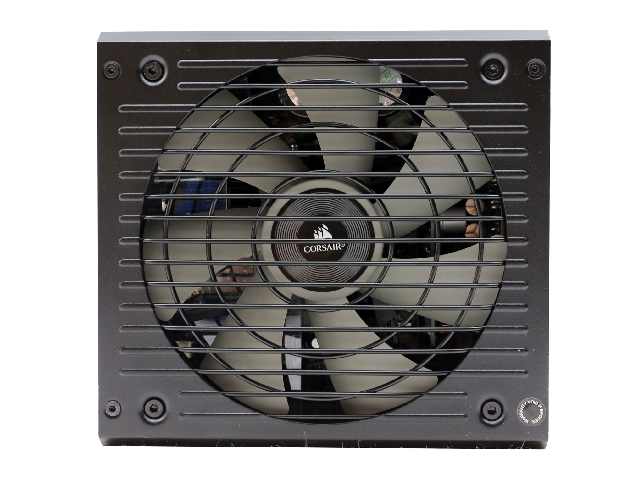
| Cooling | 135mm Rifle Bearing Fan (NR135L) |
| Semi-Passive Operation | ✓ (non-selectable) |
| Dimensions (W x H x D) | 152 x 87 x 162mm |
| Weight | 1.66 kg (3.66 lb) |
| Form Factor | ATX12V v2.4, EPS 2.92 |
| Warranty | 10 Years |
The unit is 80 PLUS Gold certified while in the Cybenetics scale it scores ETA-A and LAMBDA-A+, for efficiency and noise respectively. While a ETA-A rating is common for a high-end power supply, this is not the case with the LAMBDA-A+ rating which is very rare for a 850W unit.
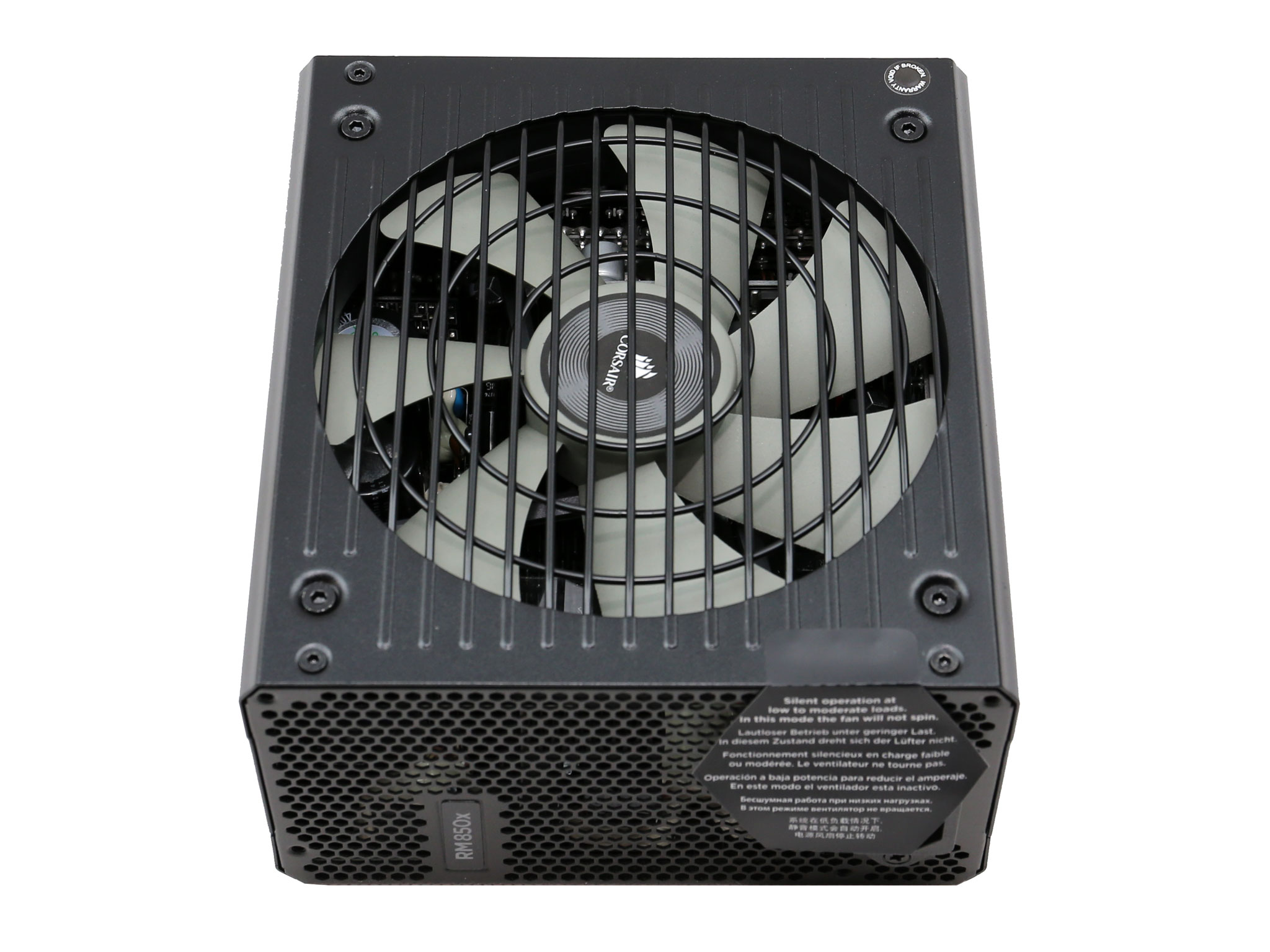
The maximum operating temperature for continuous full load delivery is 50°C, as the ATX spec recommends, while all necessary protection features are present including over temperature protection, which is crucial for any PSU. The cooling duties are handled by a 135mm rifle bearing fan, which is utilized by all RMx models, both the previous and the current ones. The fan is supported by a semi-passive mode which cannot be deactivated, unfortunately.
The previous RM850x was quite large since it measured 182mm in length while the new one is 20mm shorter. This means less hassle during the installation process, especially if the PSU compartment of the chassis is small. Finally, the provided warranty is extra long at ten years, showing Corsair's and CWT's faith in this platform.
Power Specifications
| Rail | 3.3V | 5V | 12V | 5VSB | -12V | |
| Max. Power | Amps | 25 | 25 | 70.8 | 3 | 0.8 |
| Watts | 150 | 850 | 15 | 9.6 | ||
| Total Max. Power (W) | 850 | |||||
This is a single +12V rail PSU, able to deliver its full power on this rail. The minor rails are too strong for any modern system, at 150W max power combined, while the 5VSB can deliver up to three Amps, on papers at least since in reality it is much stronger.
Cables & Connectors
| Modular Cables | ||||
| Description | Cable Count | Connector Count (Total) | Gauge | In Cable Capacitors |
|---|---|---|---|---|
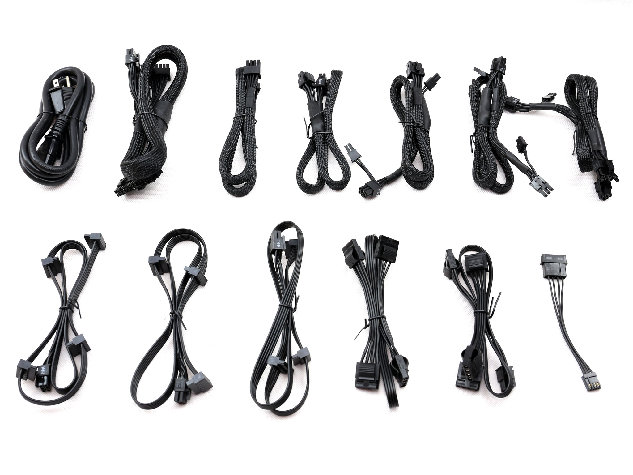
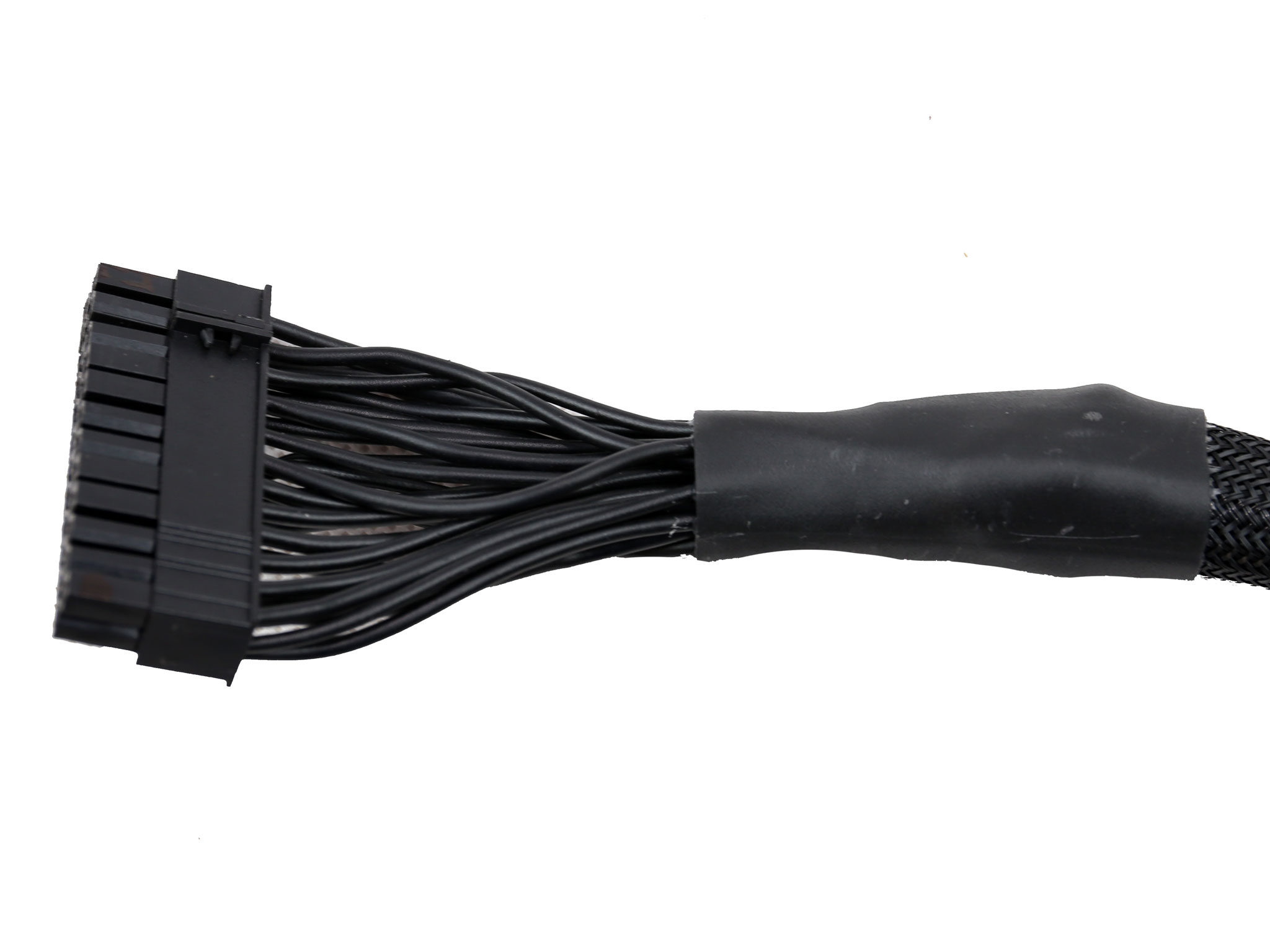
| ATX connector 20+4 pin (600mm) | 1 | 1 | 18-20AWG | Yes |
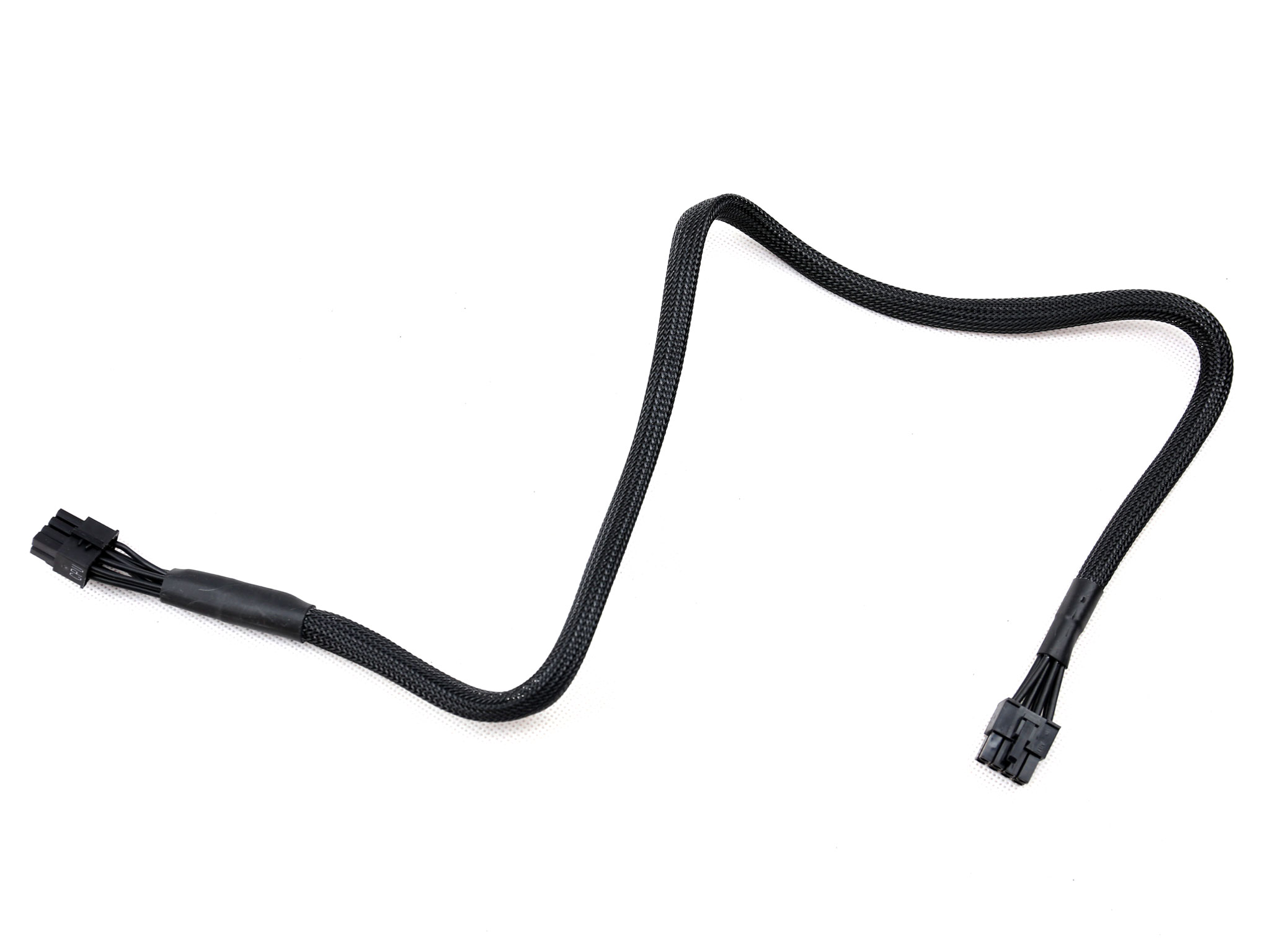
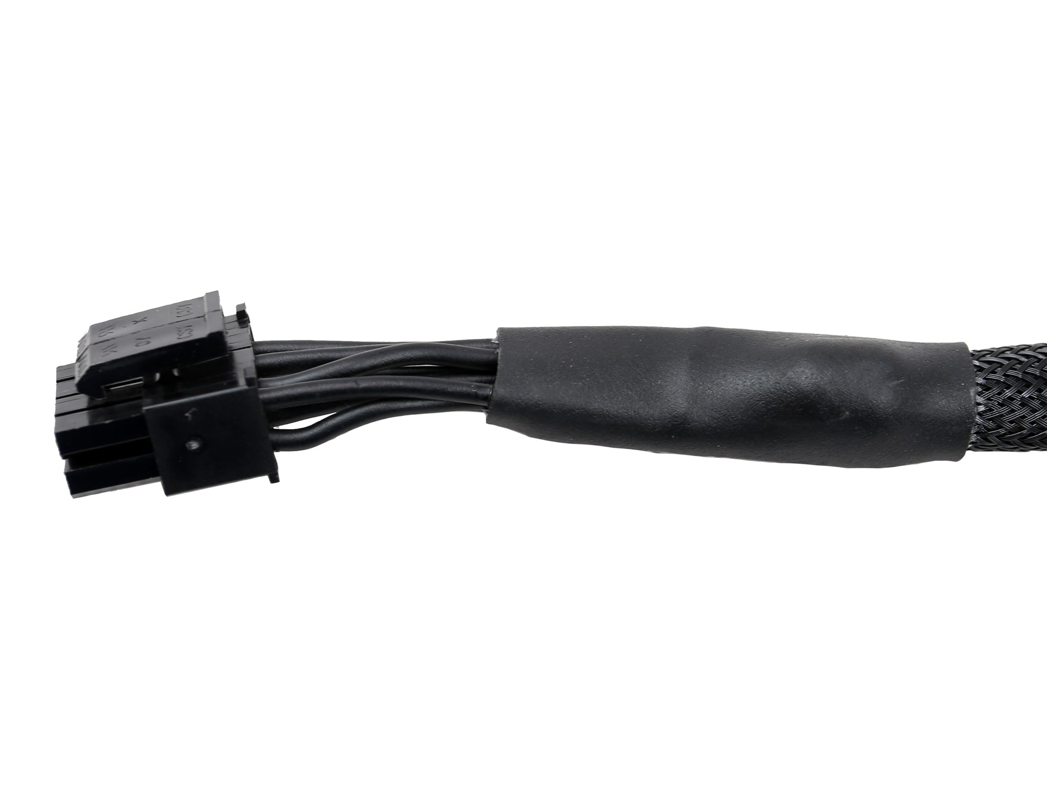
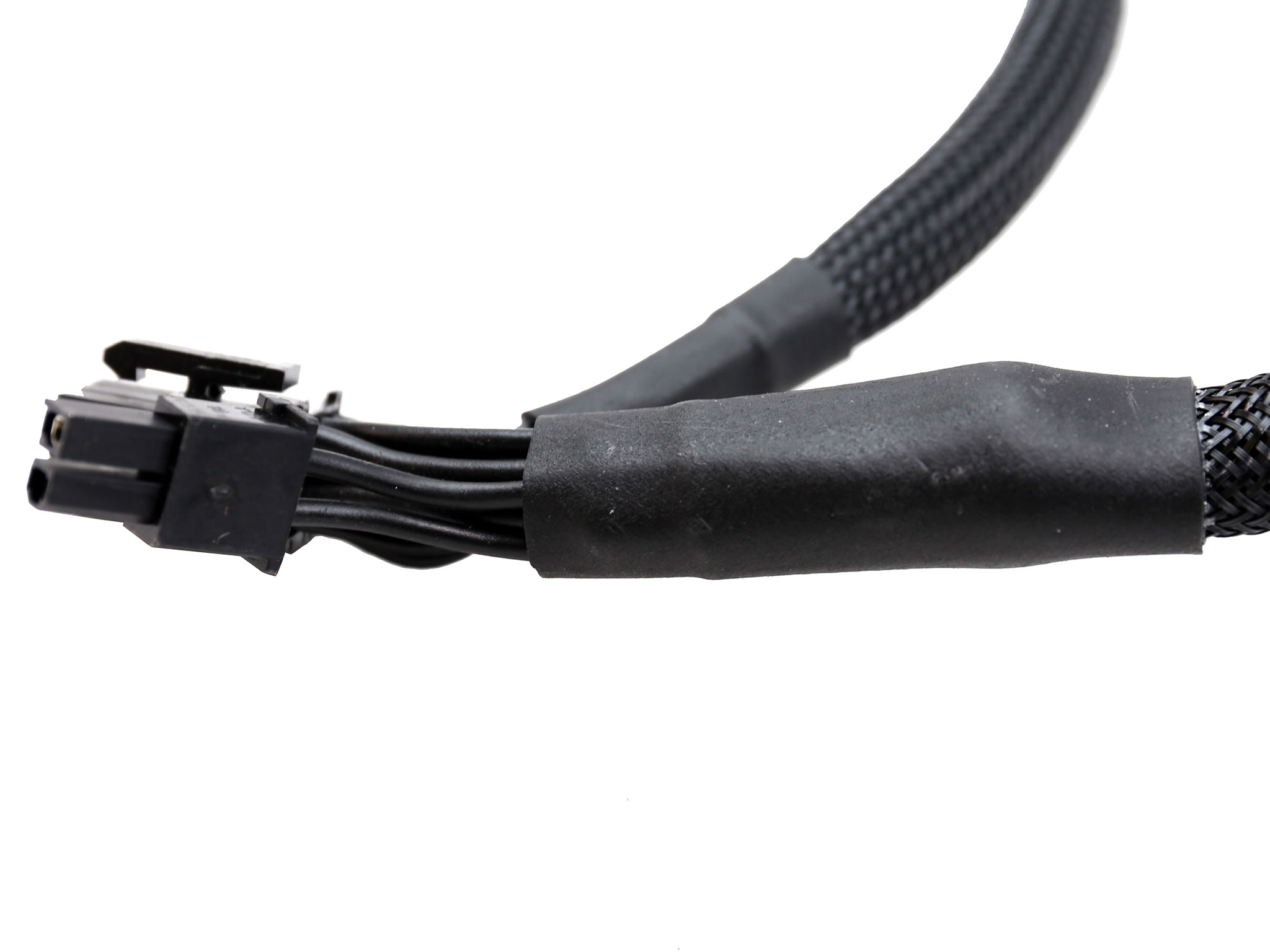
| 4+4 pin EPS12V (650mm) | 2 | 2 | 18AWG | Yes |
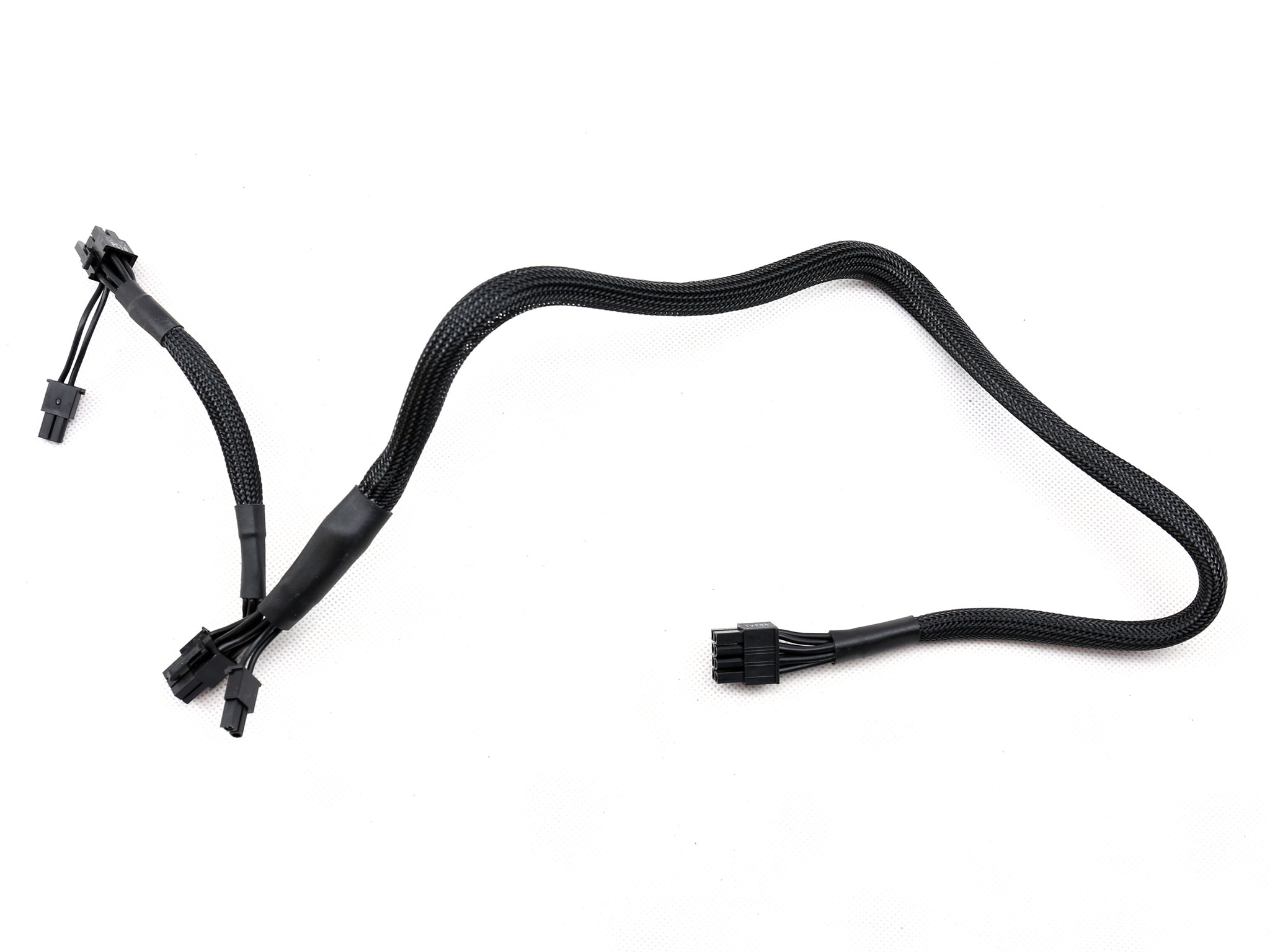
| 6+2 pin PCIe (600mm+150mm) | 3 | 6 | 18AWG | Yes |
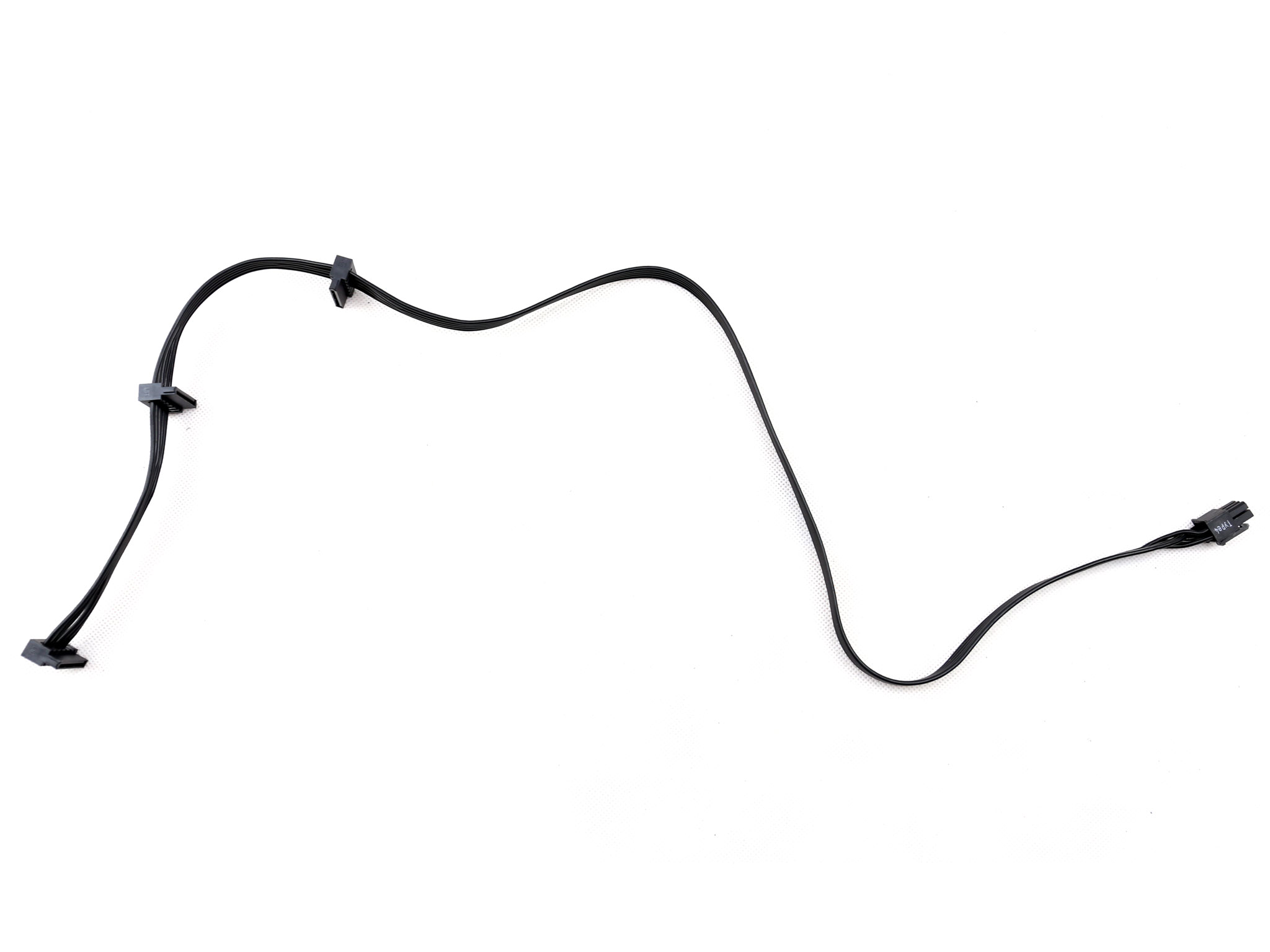
| SATA (500mm+110mm+110mm+110mm) | 1 | 4 | 18AWG | No |
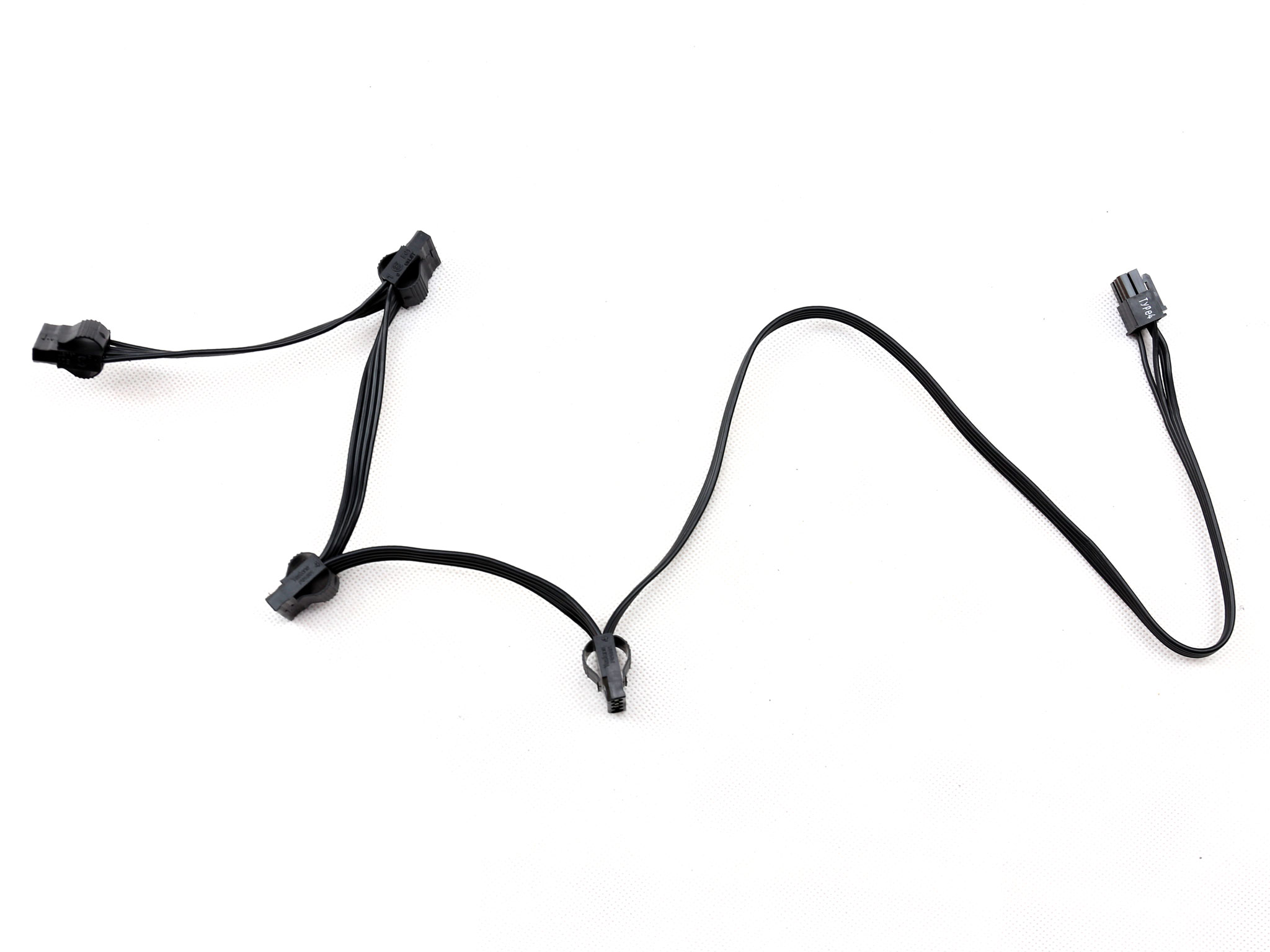
| SATA (520mm+110mm+110mm) | 2 | 6 | 18AWG | No |
| 4-pin Molex (450mm+100mm+100mm+100mm) | 2 | 8 | 18AWG | No |
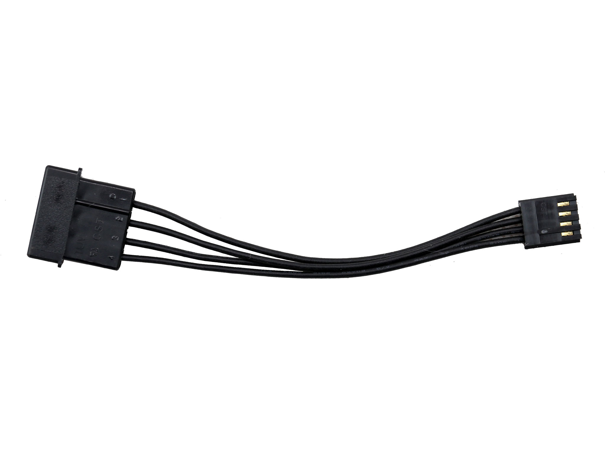
| FDD Adapter (+100mm) | 1 | 1 | 20AWG | No |
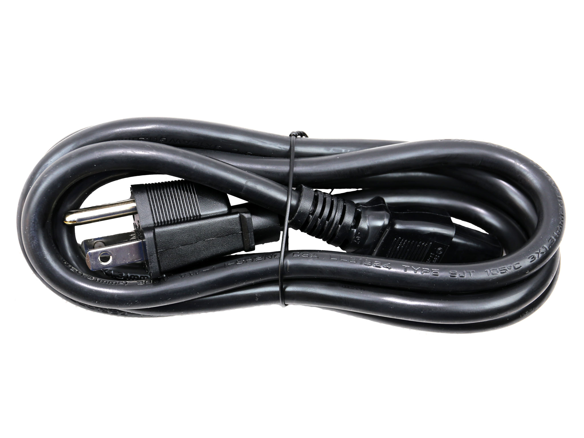
| AC Power Cord (1430mm) – C13 coupler | 1 | 1 | 16AWG | – |
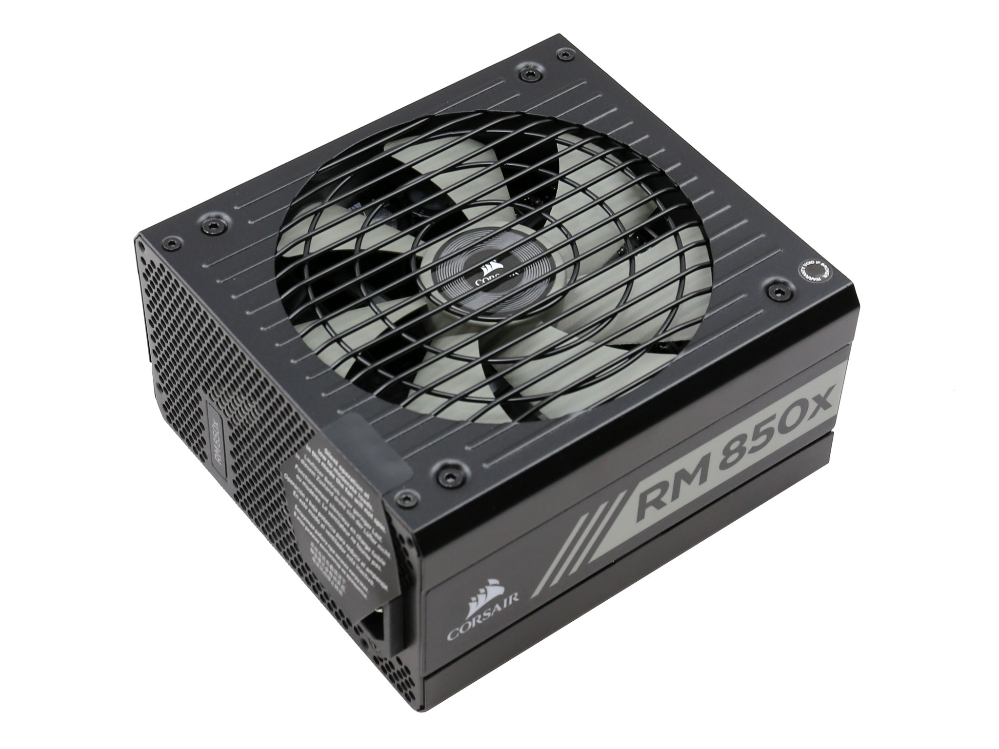
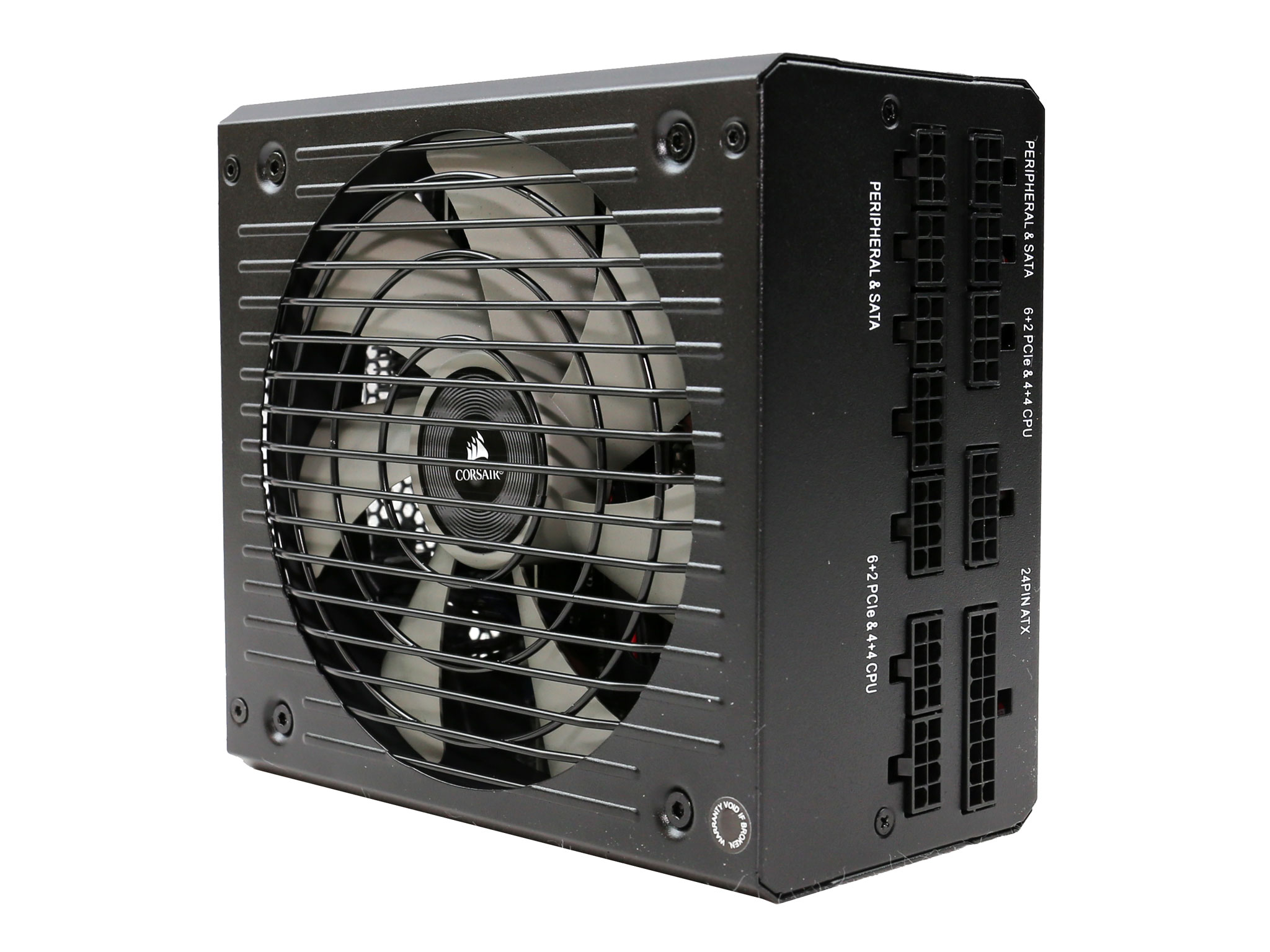
There are two EPS connectors, something that we find essential in a 850W power supply. The number of PCIe connectors is satisfactory as well and the same goes for the SATA and 4-pin Molex. Corsair also provides a Berg (FDD) adapter for the users that still need it.
All cables are long enough, but the distance between the peripheral connectors is small at only 10cm. Finally, the ATX, EPS and PCIe cables feature inline caps for even better ripple suppression.
Packaging
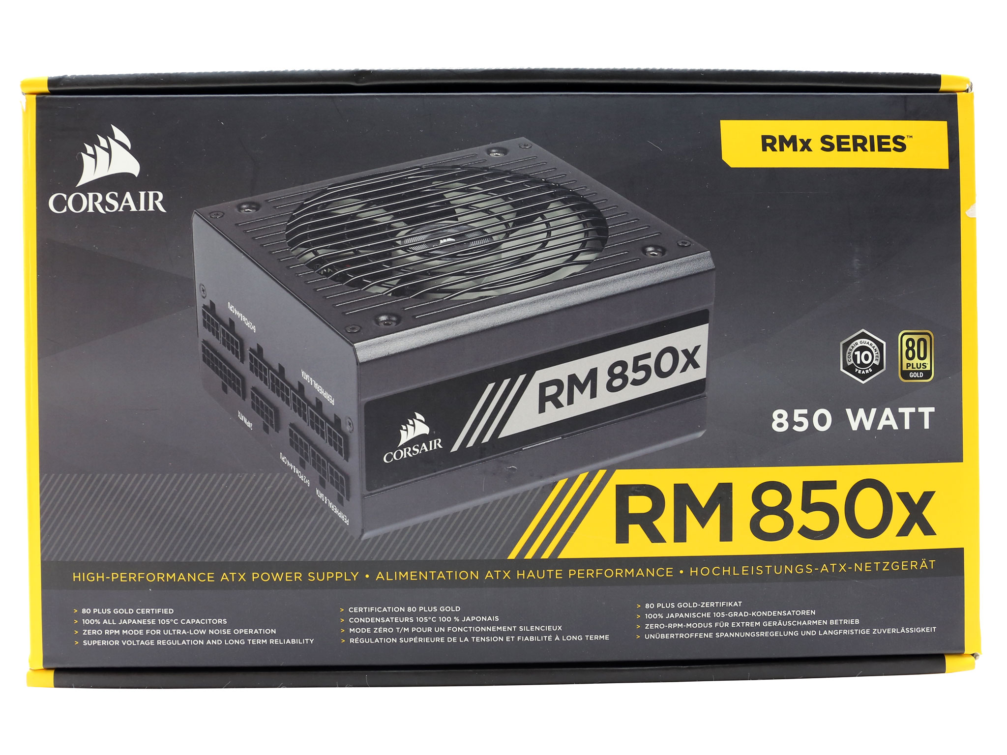
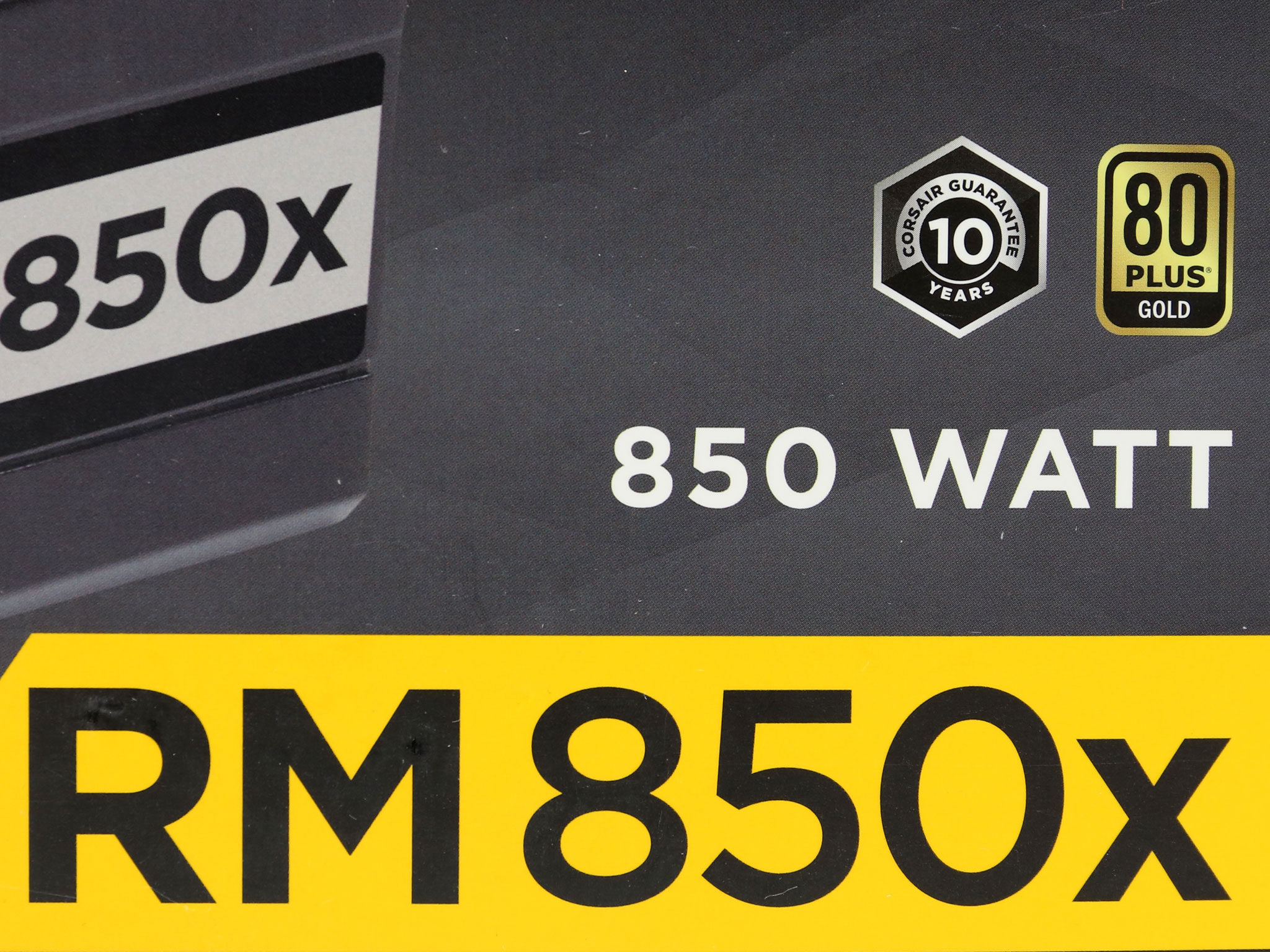
At the face of the box is an angled photo of the power supply, with the side sticker and the modular panel in view. The model number is given in large fonts while above it two badges depict the ten-year warranty and the 80 PLUS Gold certification.
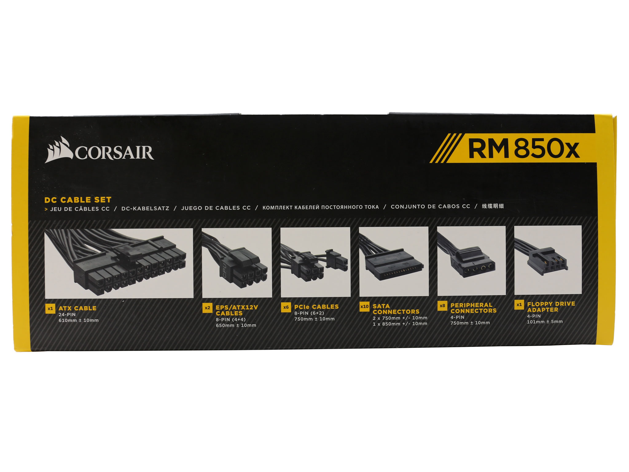
On the top side of the box you will find a list of the available cables and connectors, while a small sticker at the bottom side will help you spot the new RMx model. Just pay attention to the “2018” year right next to the model number.
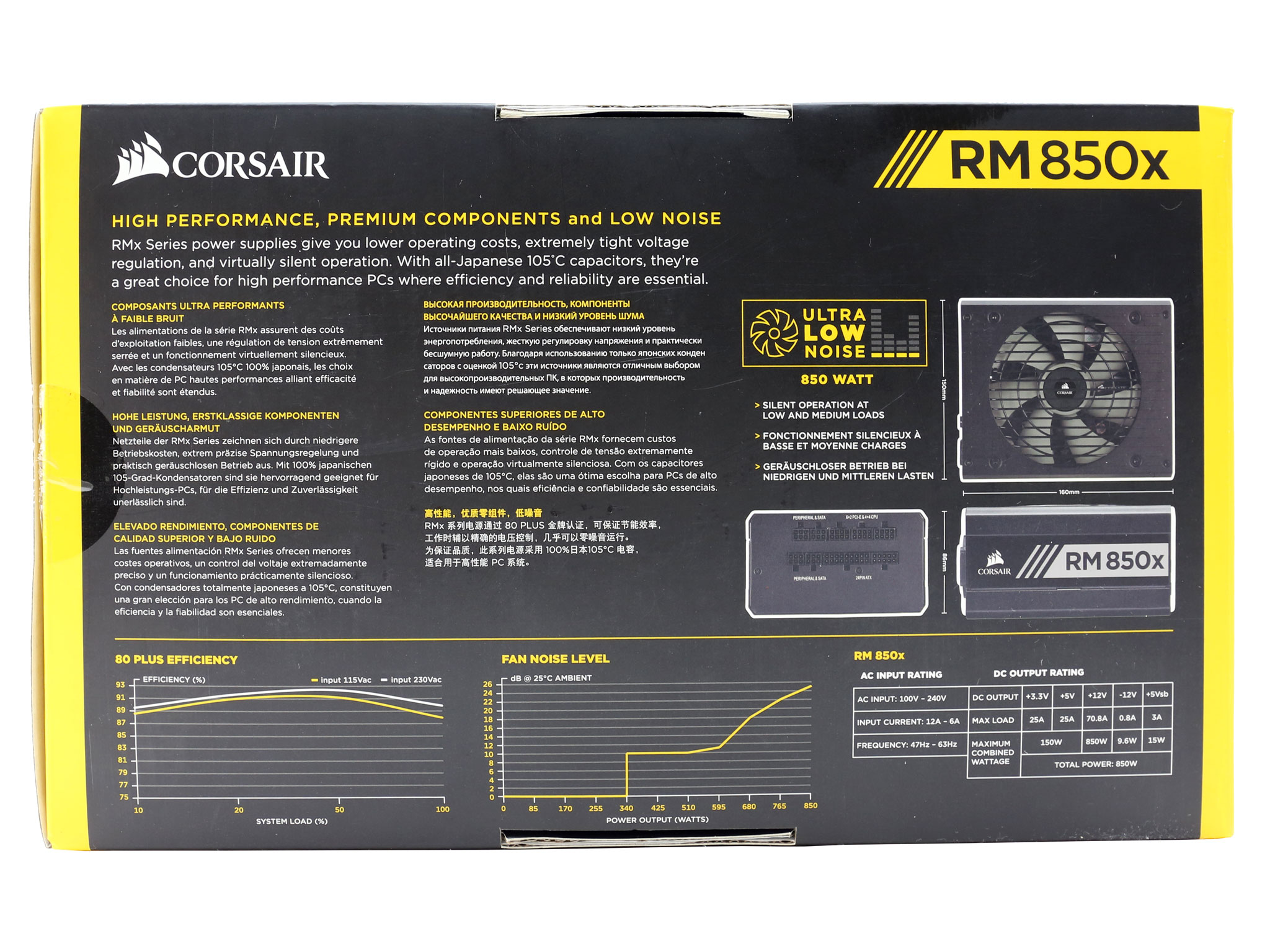
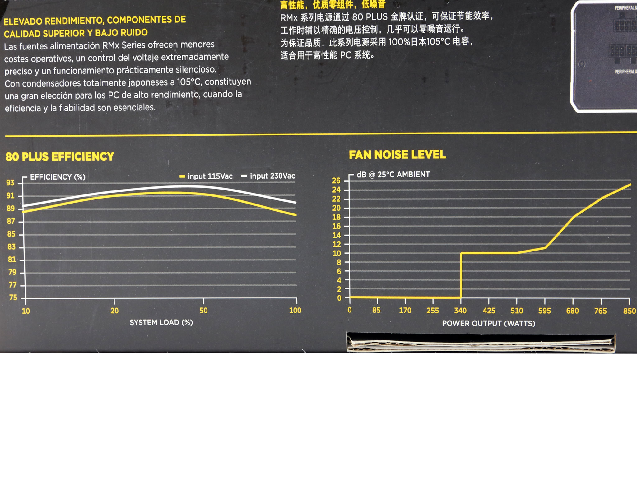
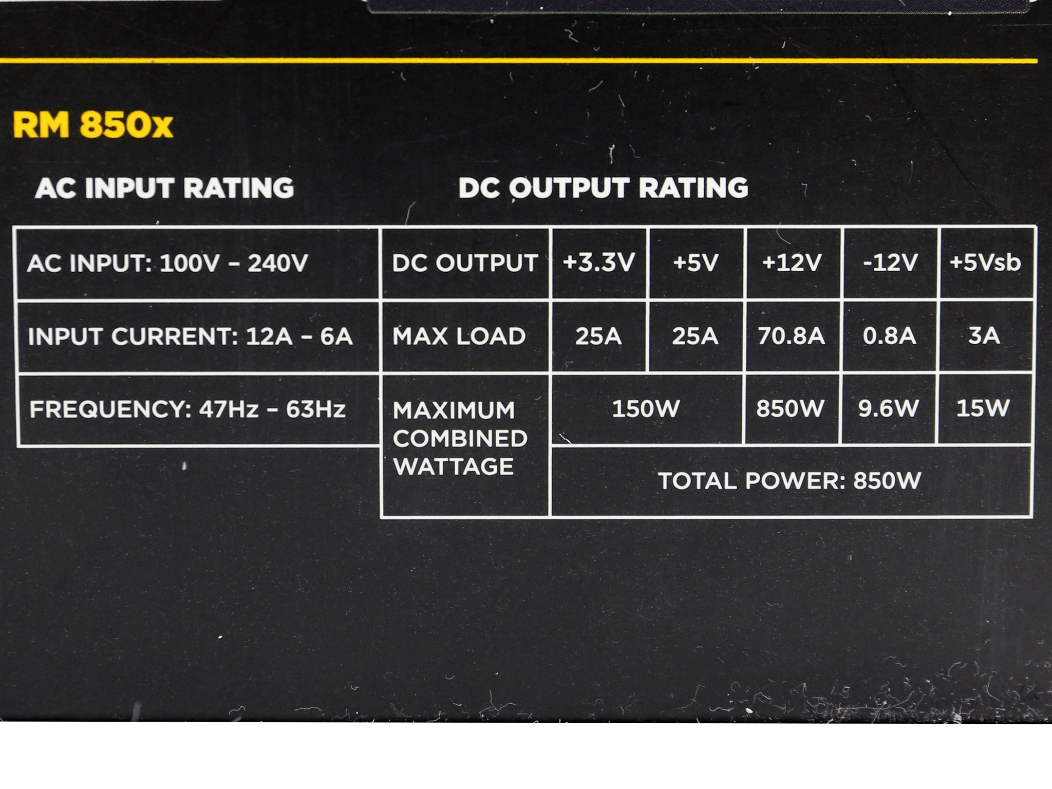
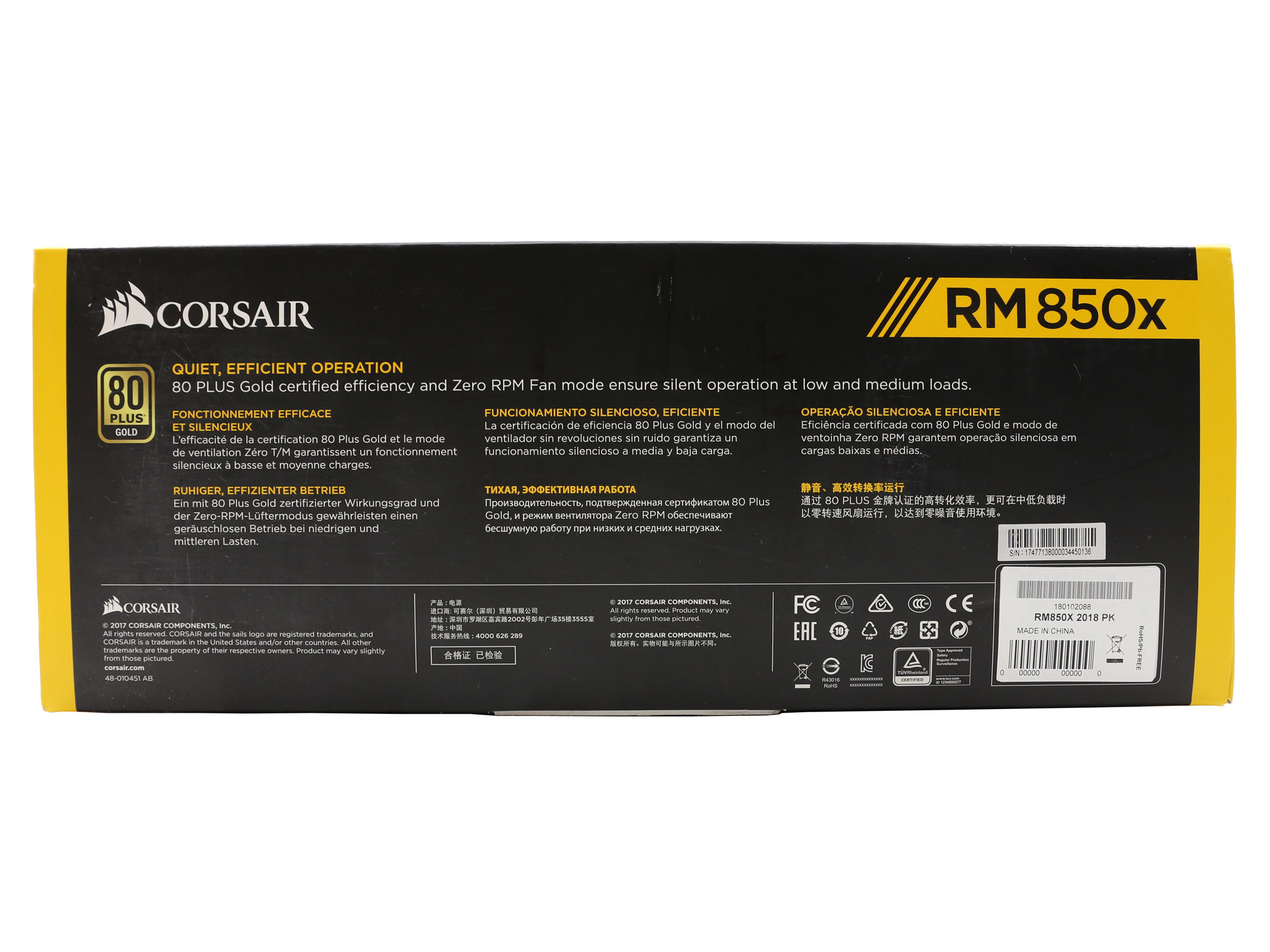
Around the back Corsair provides the unit's dimensions, its most important features and two charts showing the efficiency and fan's noise curves.
Contents
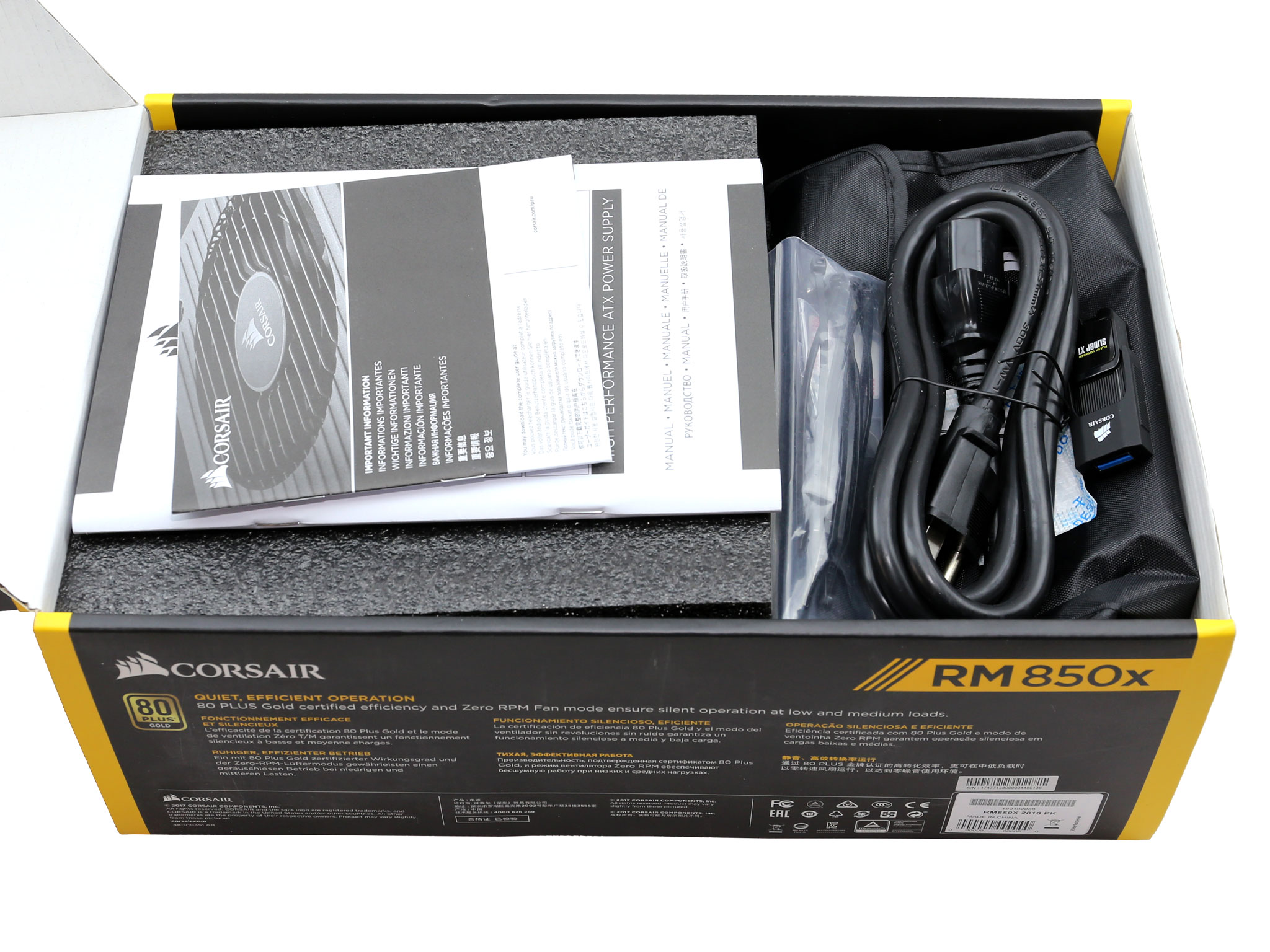
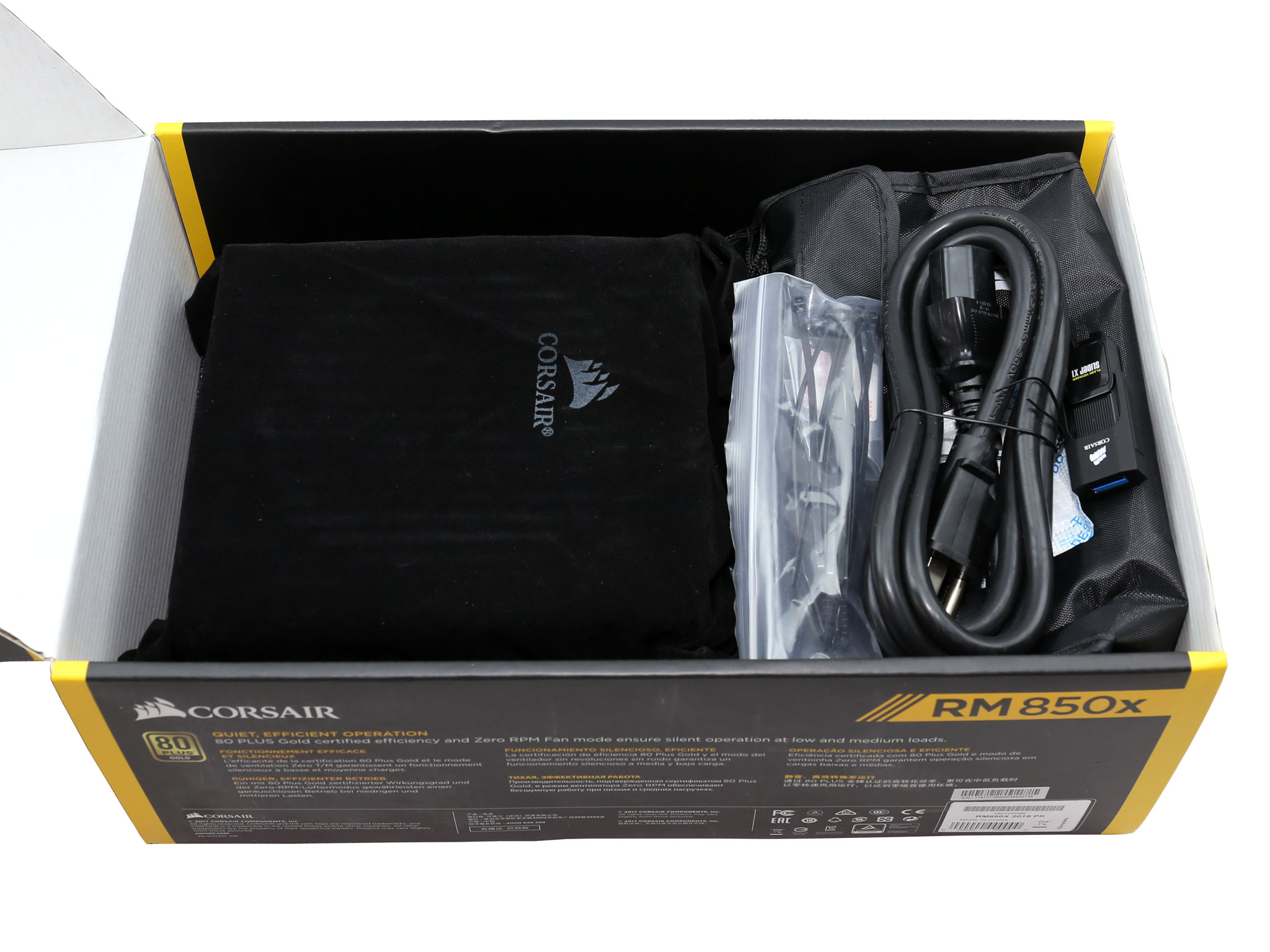

The unit is protected well into the box and it is also stored into a cloth bag, featuring Corsair's logo. It is nice to see products with adequate in-box protection since this minimize the DOA (Dead on Arrival) situations due to extreme shipping conditions, for example when the delivery person decides to play “go fetch” with the package etc.
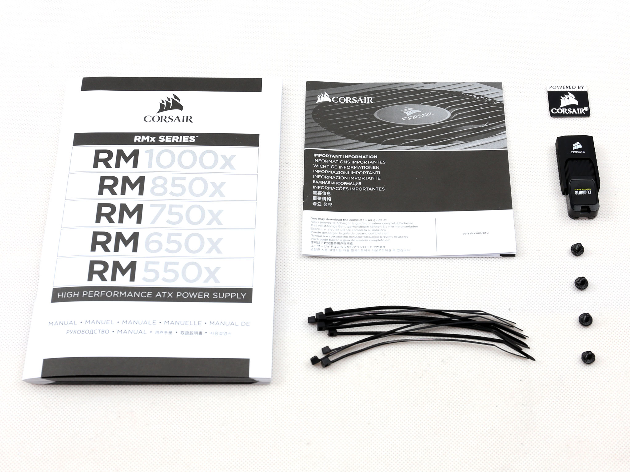
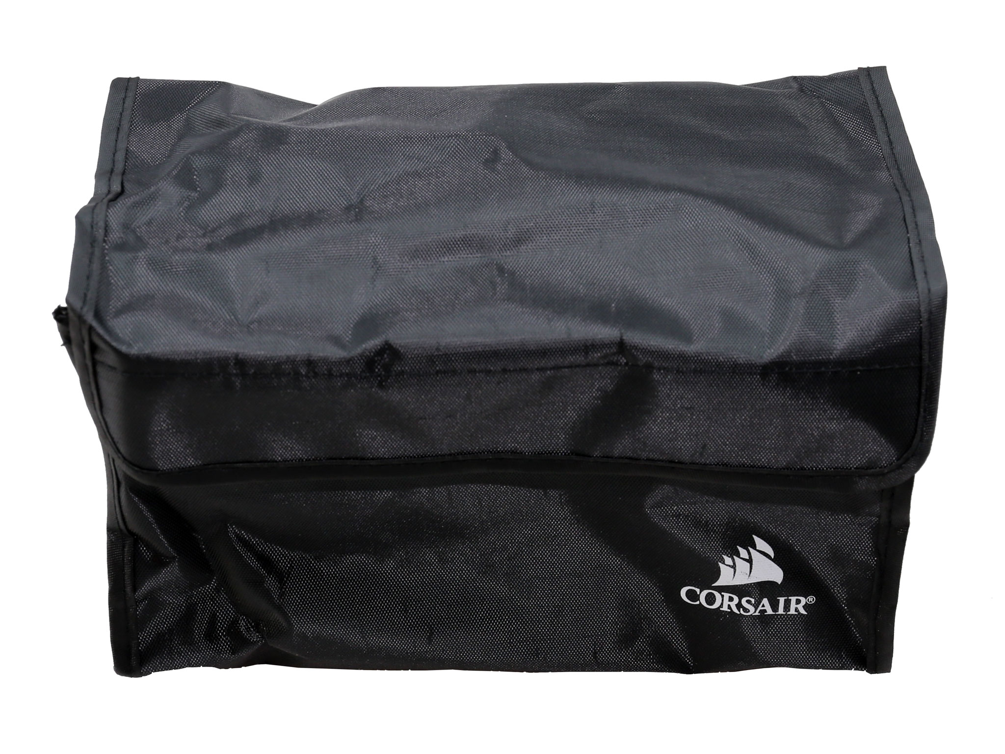
The bundle includes the user's manual, which is common across all RMx models, a warranty leaflet, a number of zip-ties, some fixing bolts, a case badge, a pouch for storing the cables and if you are a reviewer you will also get a Corsair flash drive containing a Chroma report for the specific sample.
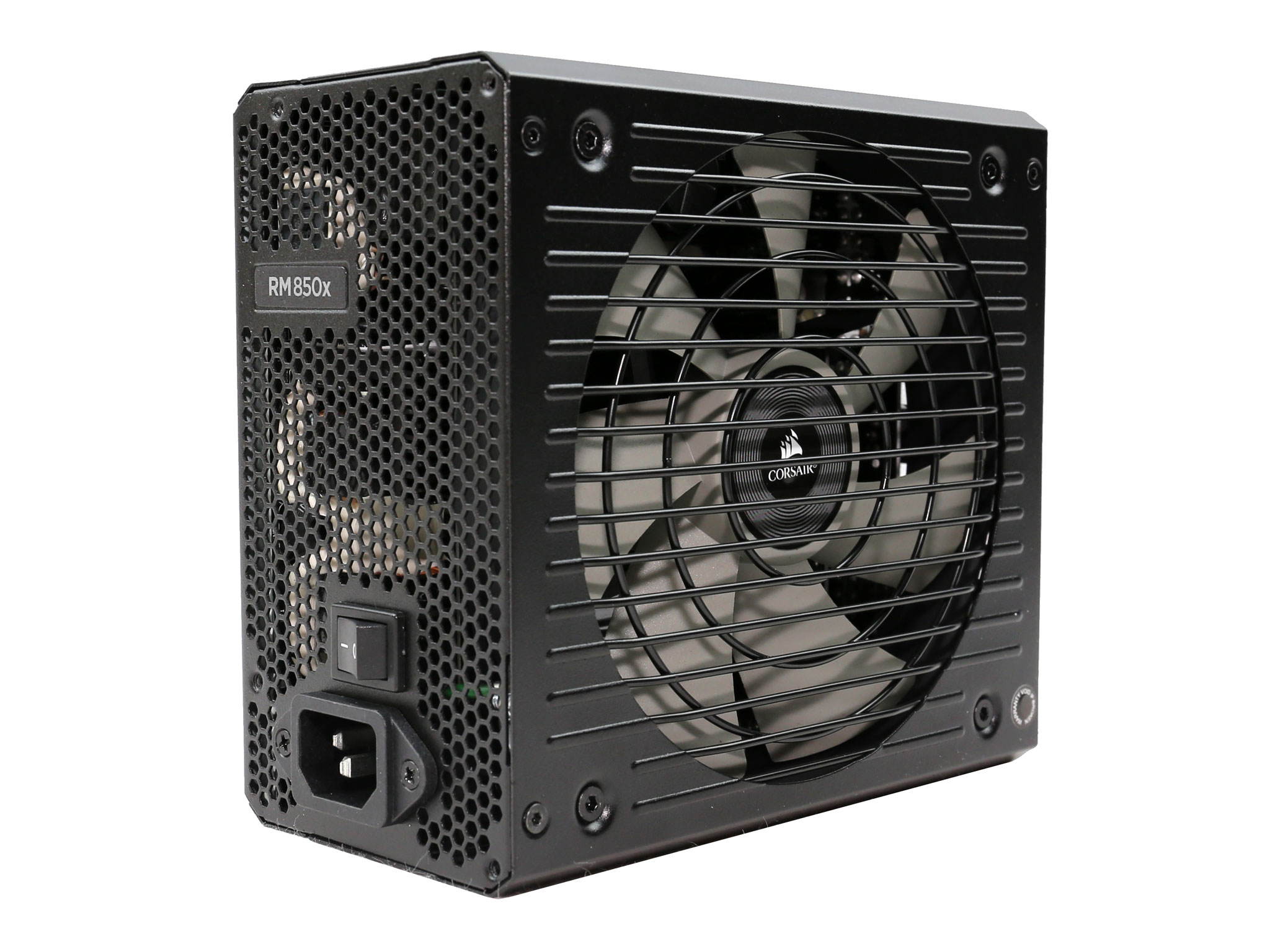
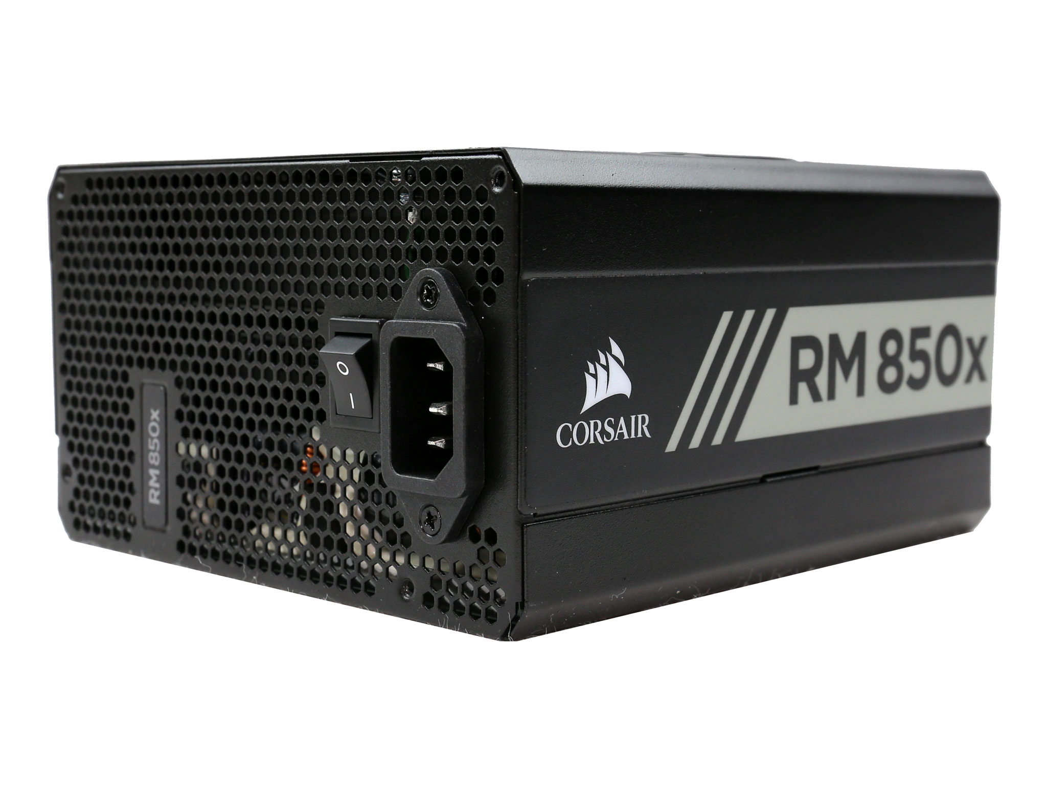
Exterior
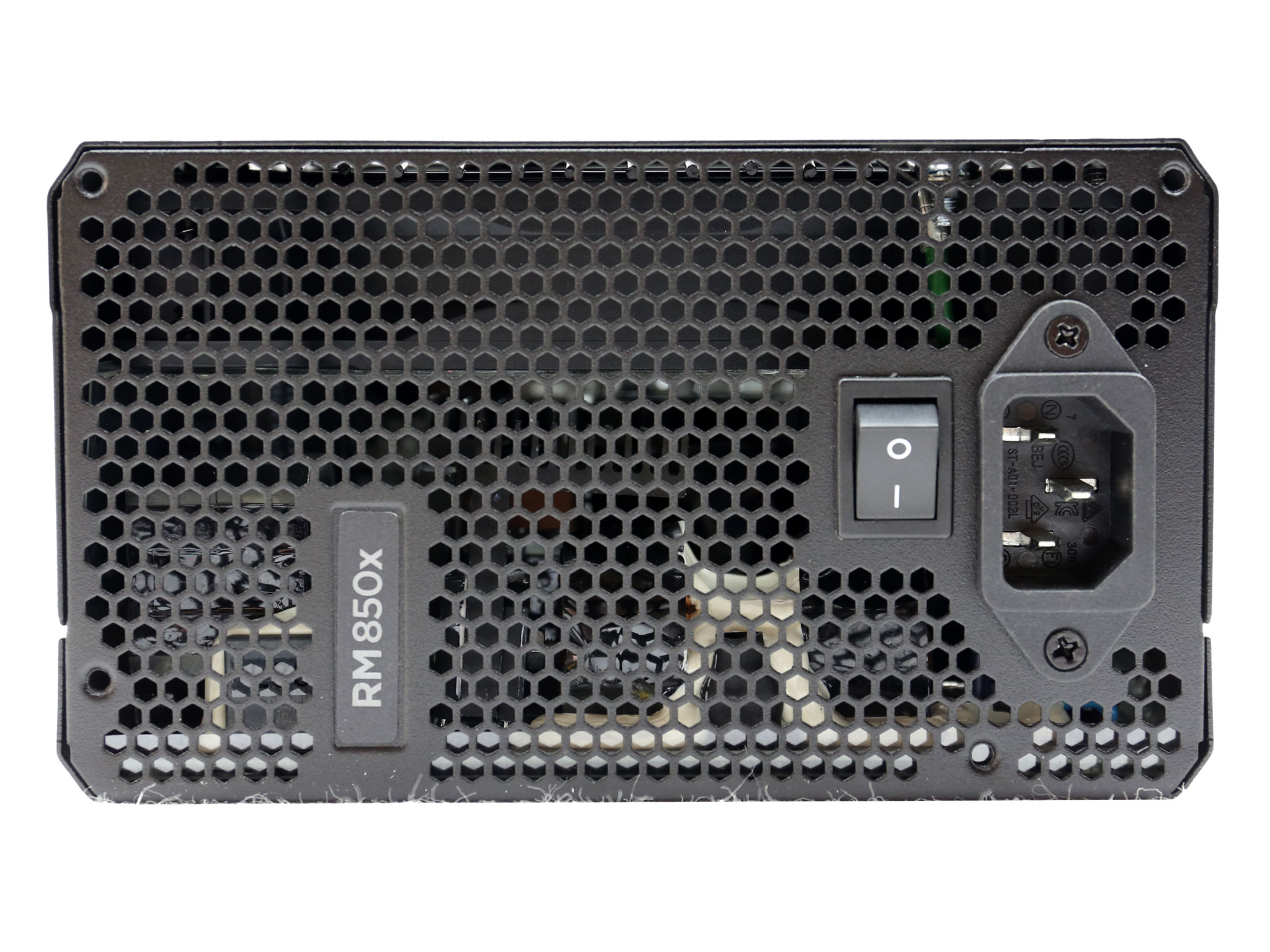
A sticker covers the AC receptacle and the power switch, informing that this unit has a semi-passive fan mode so it is normal for the fan not to spin under light loads. This way you get to deal effectively with users that don't know about semi-passive PSUs.
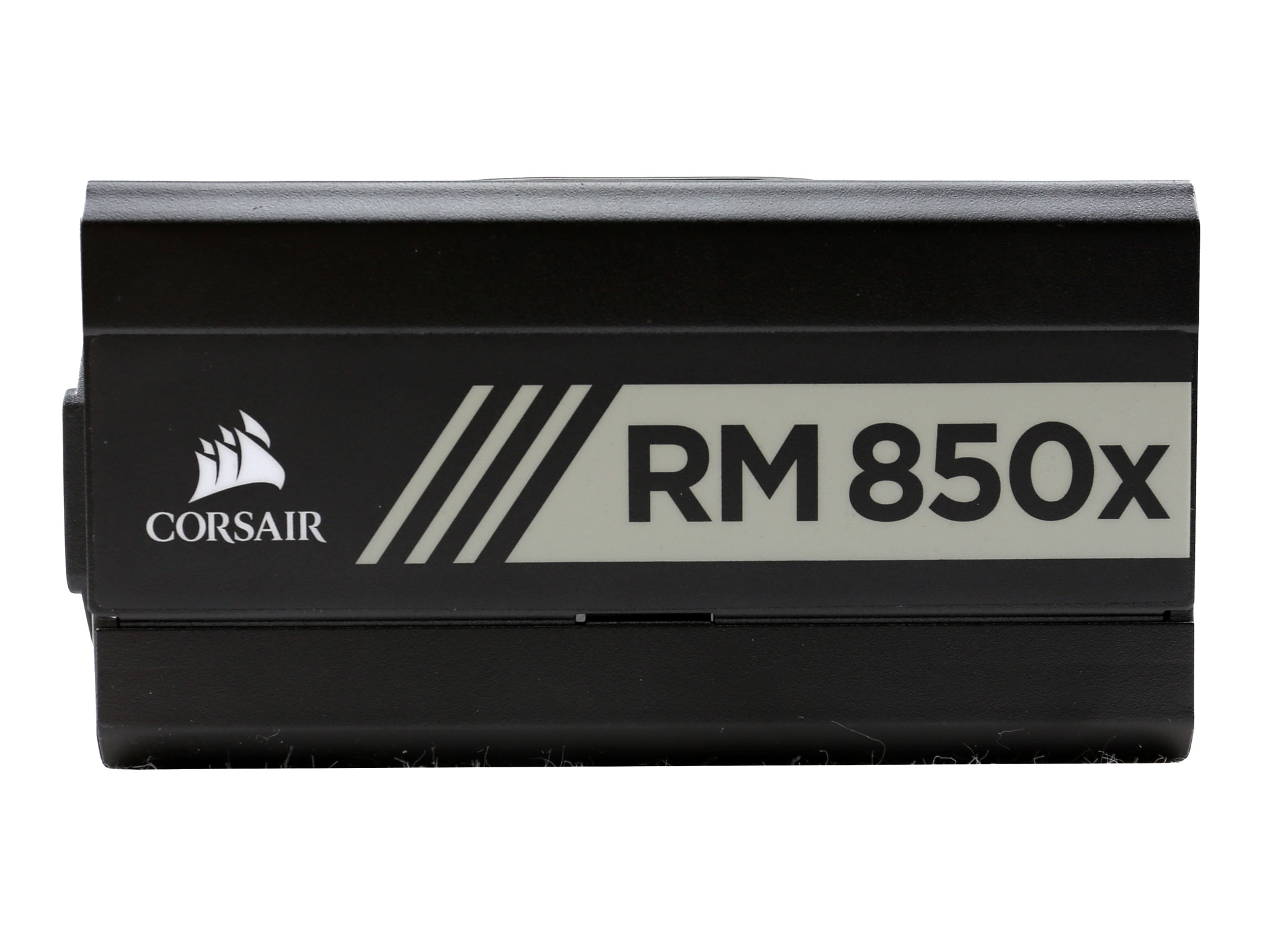
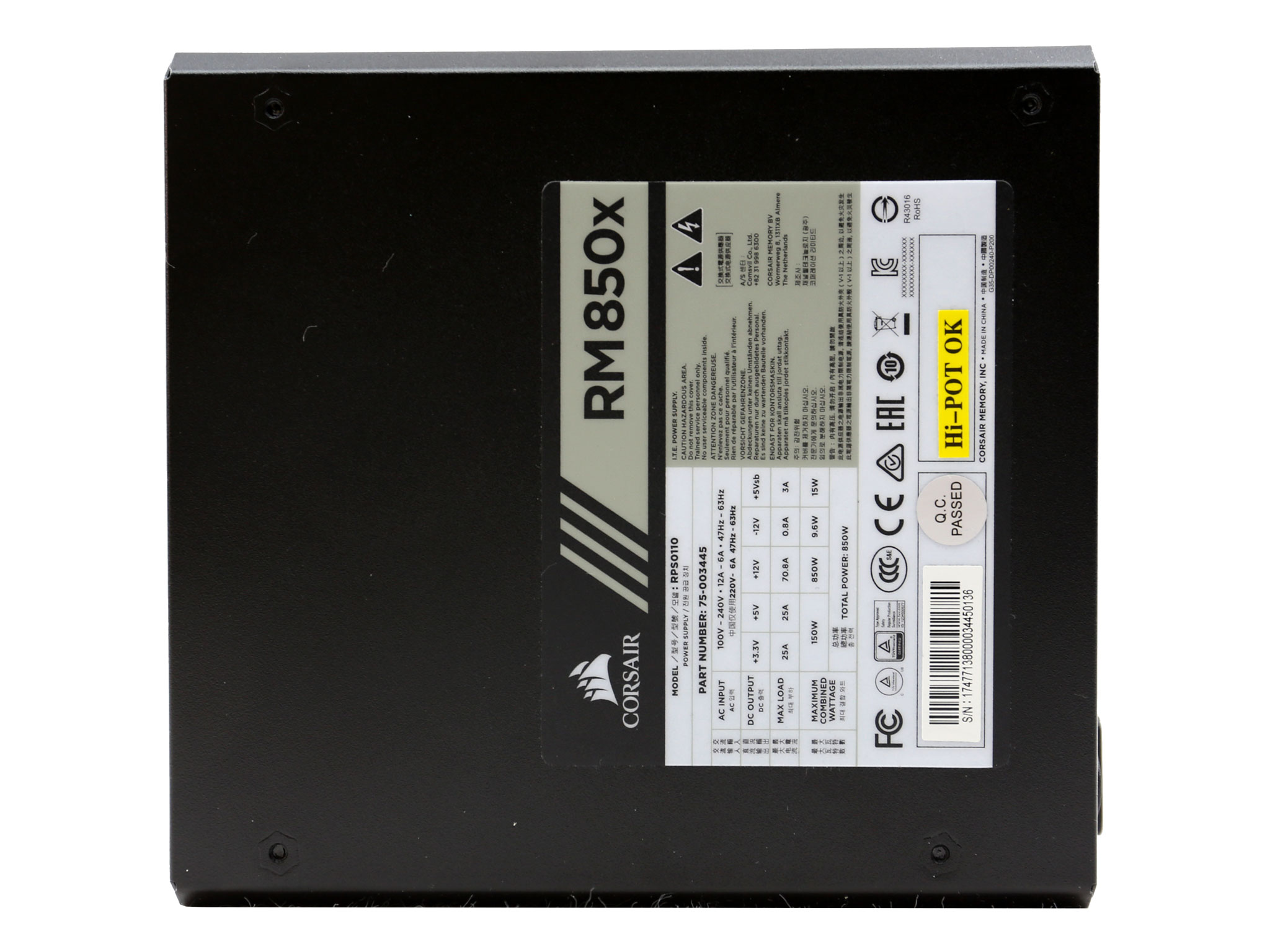
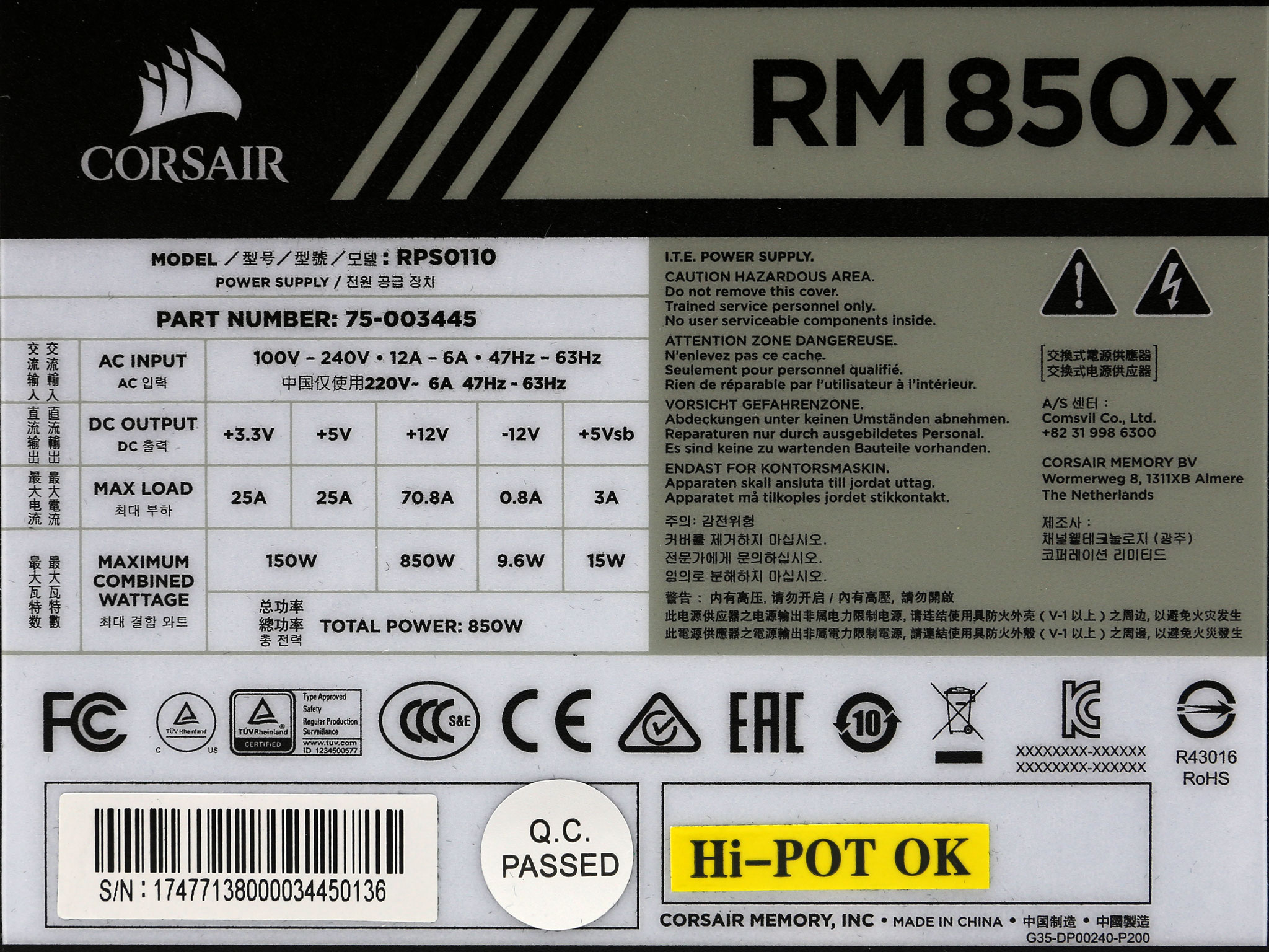
On the sides the large stickers show the model number. The power specifications label is at the bottom side, including the serial number and a High Potential (Hi-Pot) OK sticker.
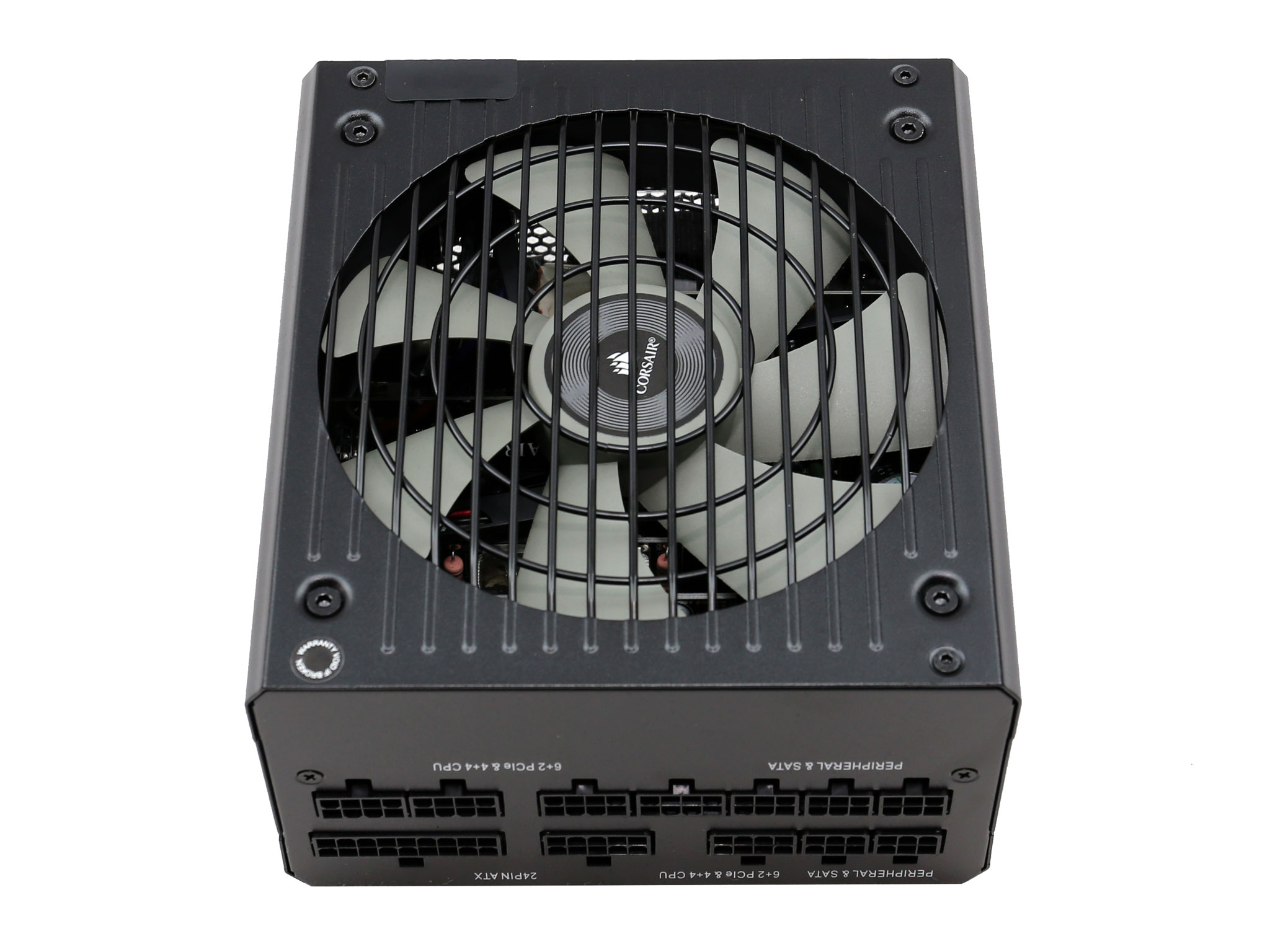
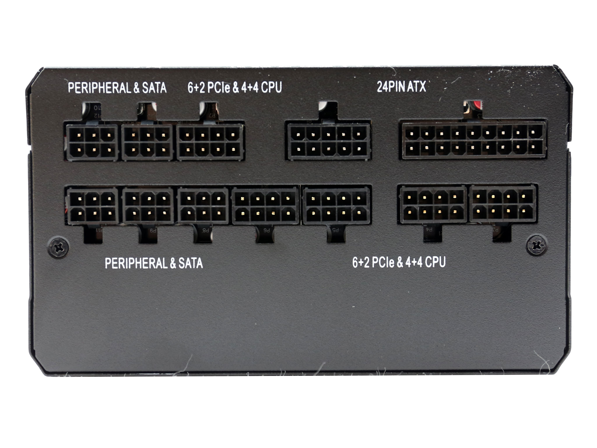
The modular panel includes twelve sockets in total, five for the peripheral cables, an equal number for the EPS and PCIe cables and a pair for the main ATX cable.
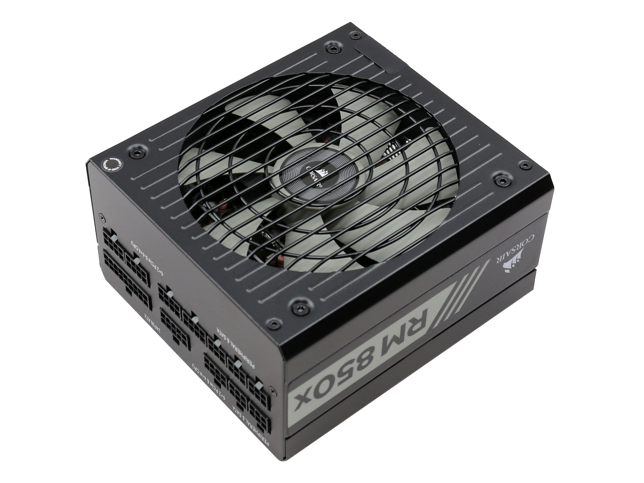
Corsair uses the same external design for quite some time now. We believe that the time has come for a change in this section, since it starts to look old and boring now.
|
General Data |
|
|
Manufacturer (OEM) |
CWT |
|
Primary Side |
|
|
Transient Filter |
4x Y caps, 2x X caps, 2x CM chokes, 1x MOV |
|
Inrush Protection |
NTC Thermistor & Relay |
|
Bridge Rectifier(s) |
2x GBU1506 (600V, 15A @ 100°C) |
|
APFC MOSFETS |
2x Infineon IPA60R125C6 (650V, 19A @ 100°C, 0.125 Ohm) |
|
APFC Boost Diode |
1x CREE C3D08060A (600V, 8A @ 152°C) |
|
Hold-up Cap(s) |
2x Nichicon (400V, 470uF each or 940uF combined, 2000h @ 105°C, GG) |
|
Main Switchers |
2x Infineon IPA60R190P6 (650V, 12.7A @ 100°C, 0.190 Ohm) |
|
APFC Controller |
Champion CM6500UNX |
|
Switching Controller |
Champion CM6901X |
|
Fan Controller |
Microchip PIC16F1503 |
|
Topology |
Primary side: Half-Bridge & LLC Resonant Controller |
|
Secondary Side |
|
|
+12V MOSFETS |
6x International Rectifier IRFH7004TRPBF (40V, 164A @ 100°C, 1.4 mOhm) |
|
5V & 3.3V |
DC-DC Converters: 6x QM3006D (30V, 57A @ 100°C, 5.5 mOhm) |
|
Filtering Capacitors |
Electrolytics: Nippon Chemi-Con (1-5,000 @ 105°C, KZE), |
|
Supervisor IC |
|
|
Fan Model |
NR135L (12V, 0.22A, Rifle Bearing) |
|
5VSB Circuit |
|
|
Rectifier |
ISD04N65A (650V, 4A, 2.5Ohm) SBR, QM3004D, LS64 10L45 SBR |
|
Step-Down Converter |
|
|
Standby PWM Controller |
On-Bright OB5269CP |
Compared to the previous generation RM850x the new has some changes. Those include a bypass relay for the NTC thermistor responsible for protection against large inrush currents. Moreover, in the primary side instead of Vishay's FETs we now find Infineon ones. Both the APFC and the LLC resonant controllers are provided by Champion. The older RMx units used Infineon controllers in those stages.

The list of changes goes on in the secondary change where the DC-DC converters utilizing six QM3006D FETs rather than a combination of four QM3004D and two QM3006D FETs. Another change here is in the fan control circuit which utilizes a micro-controller. The latter allows for a better (fine) tuning of the fan profile.
The older RM850x was based on a good platform however the new one is even better thanks to the changes mentioned above. Despite the smaller dimensions of the PCB the performance remained at the same levels and the noise output is further improved.
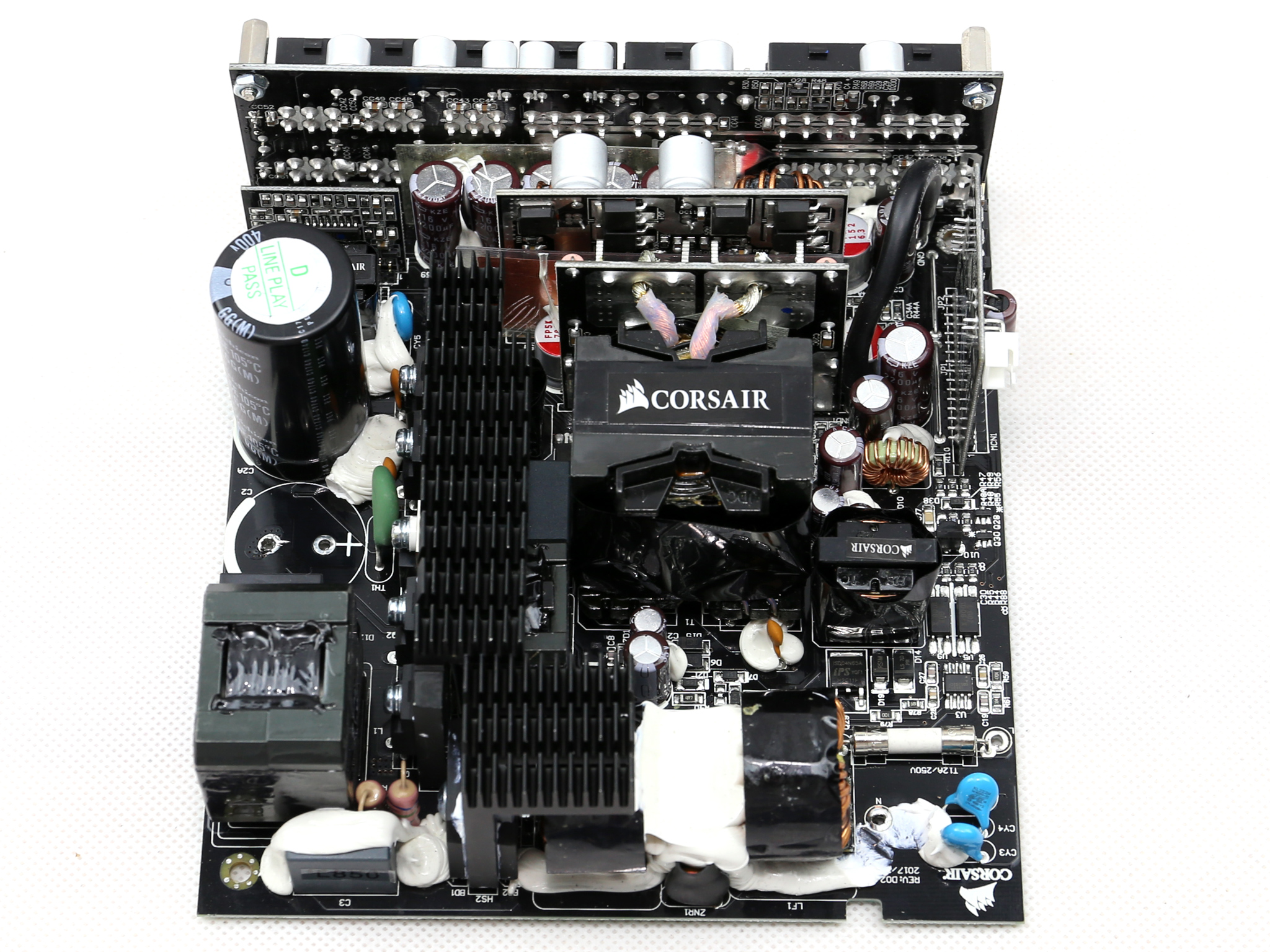
The first part of the EMI filter is on the AC receptacle including two Y and one X caps. The second part of the same filter, on the main PCB, including the same number and type of caps with the first part along with two CM chokes and an MOV.
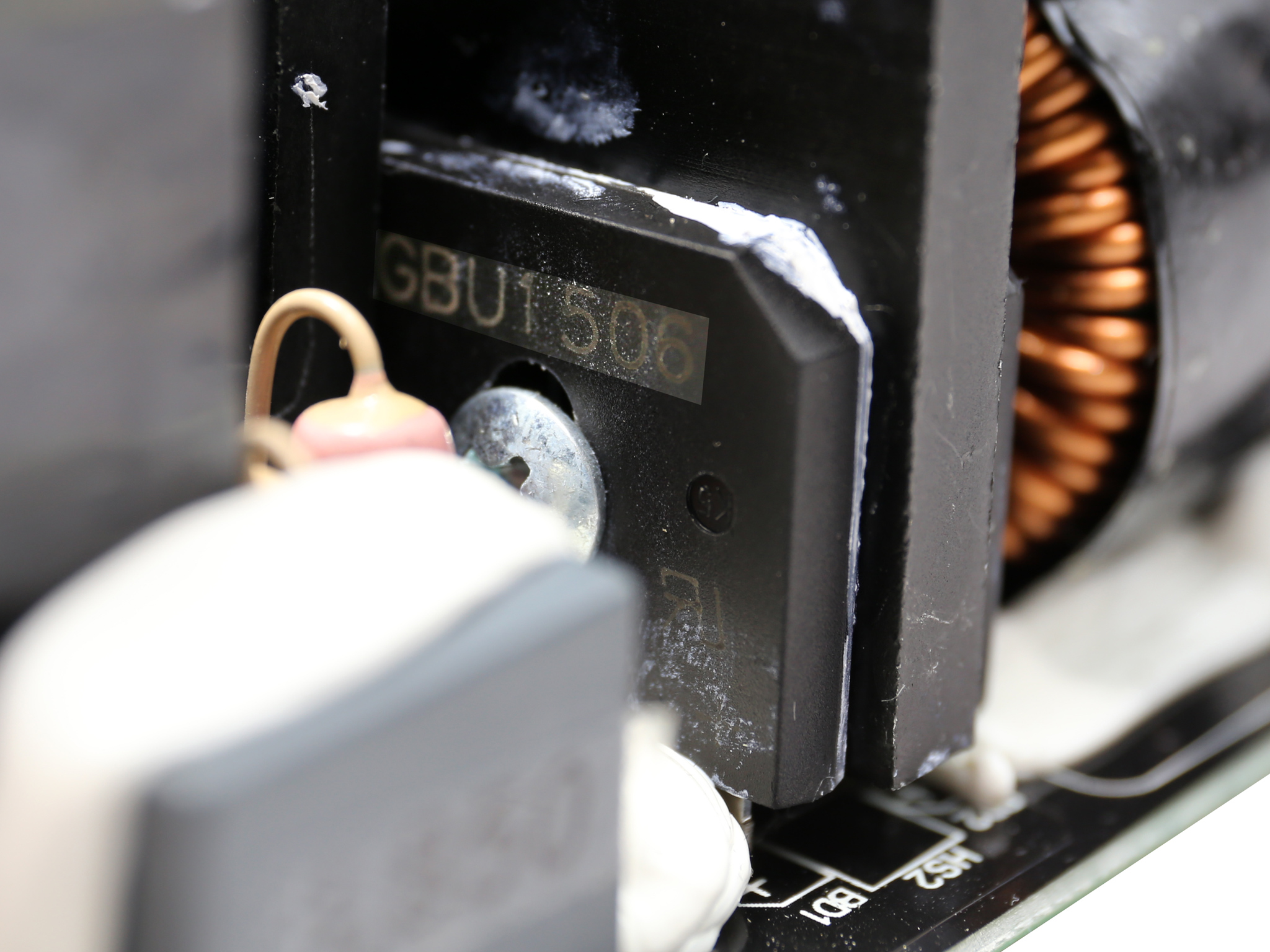
The couple of bridge rectifiers (2x GBU1506), is able to handle up to 30A so it will easily cope with the needs of a 850W unit, even with less than 100VAC input.
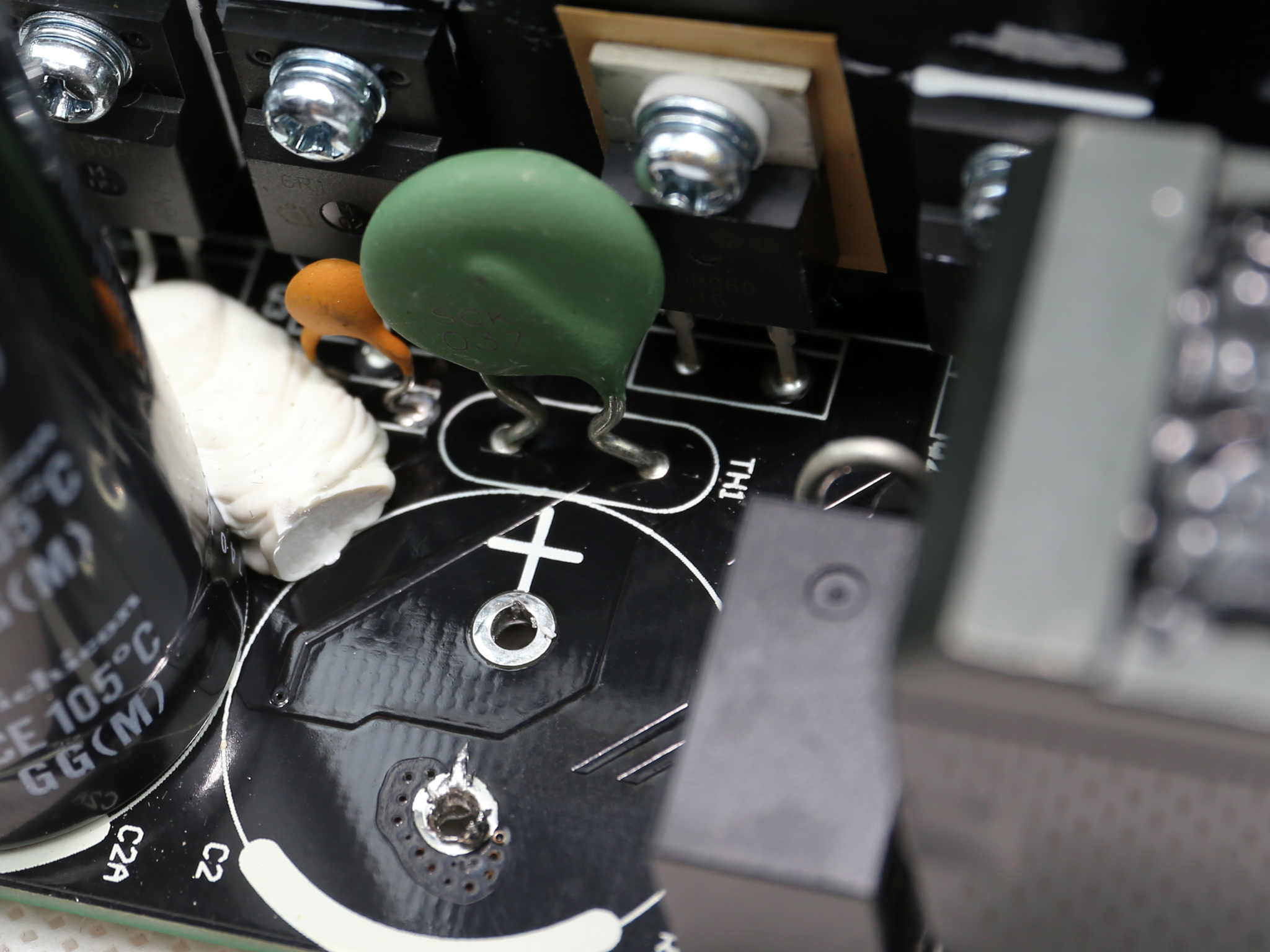
The NTC thermistor, which lowers the inrush currents that occur during the PSU's start-up phase, is now supported by a bypass relay. The relay's cost is notable, however besides a small efficiency boost it also allows the fast cool down of the thermistor, so it increases the level of protection that the later provides to the unit.
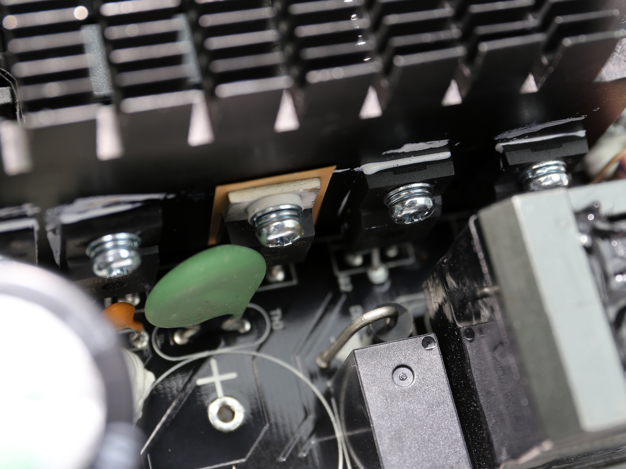
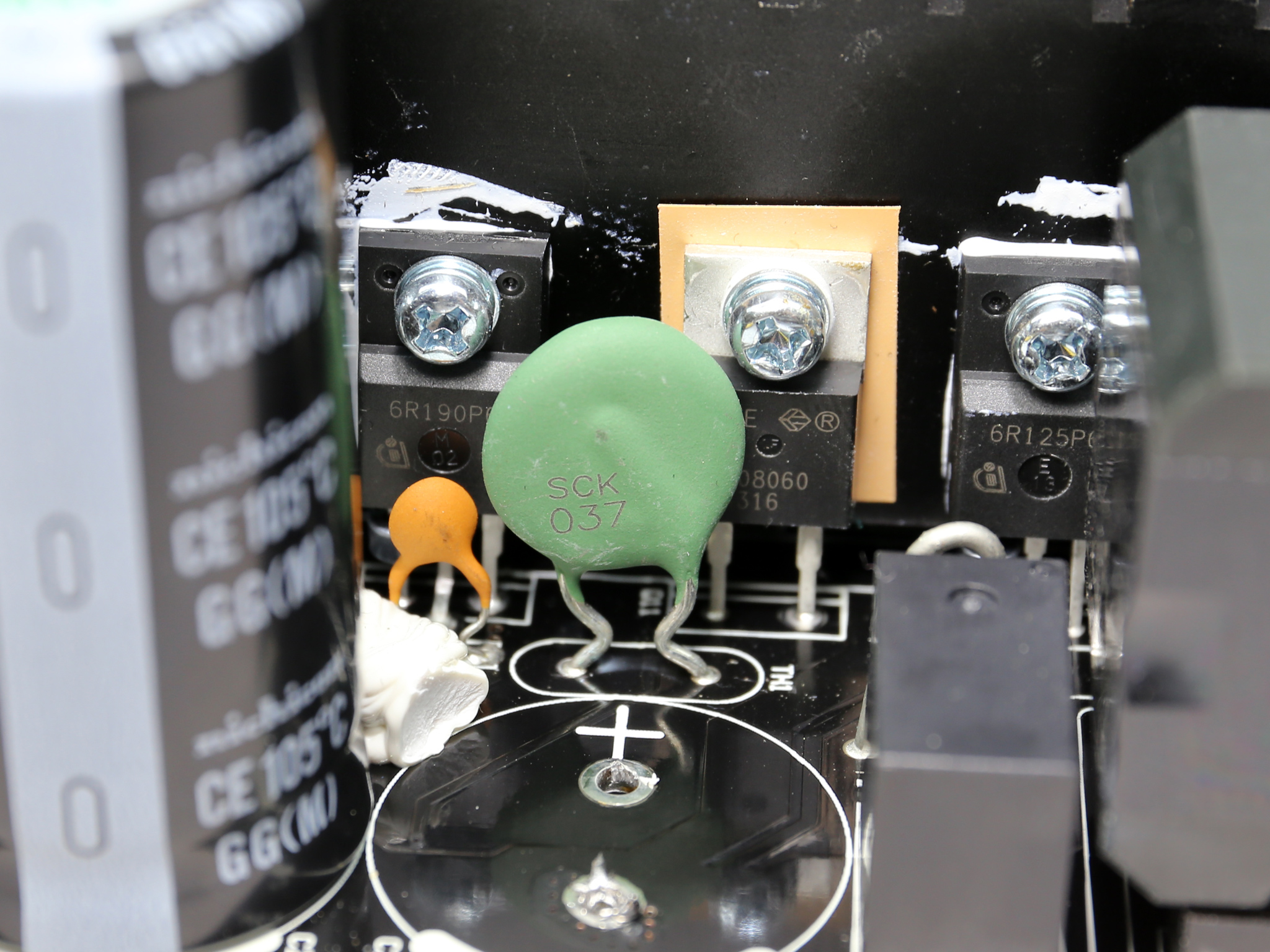
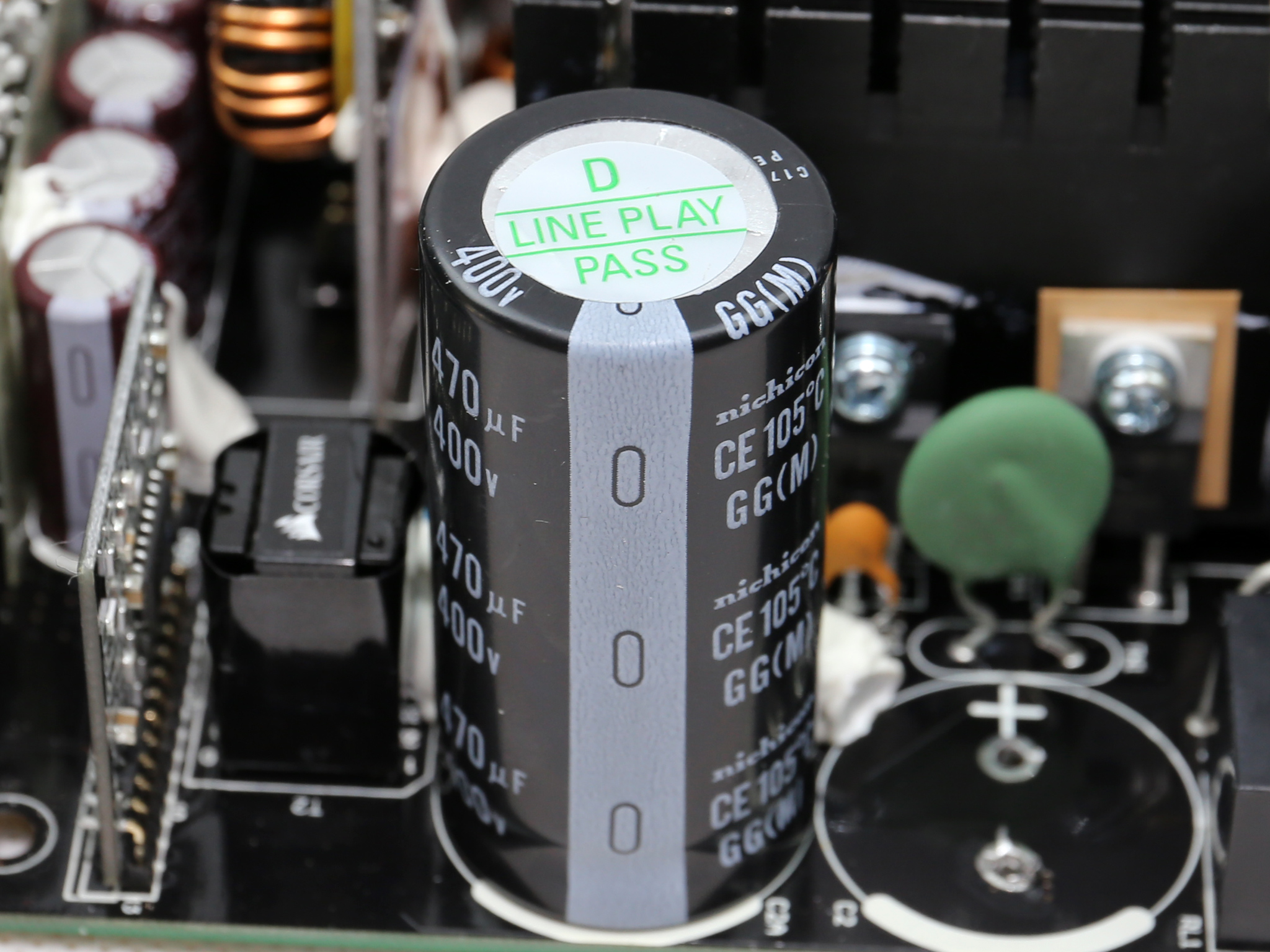
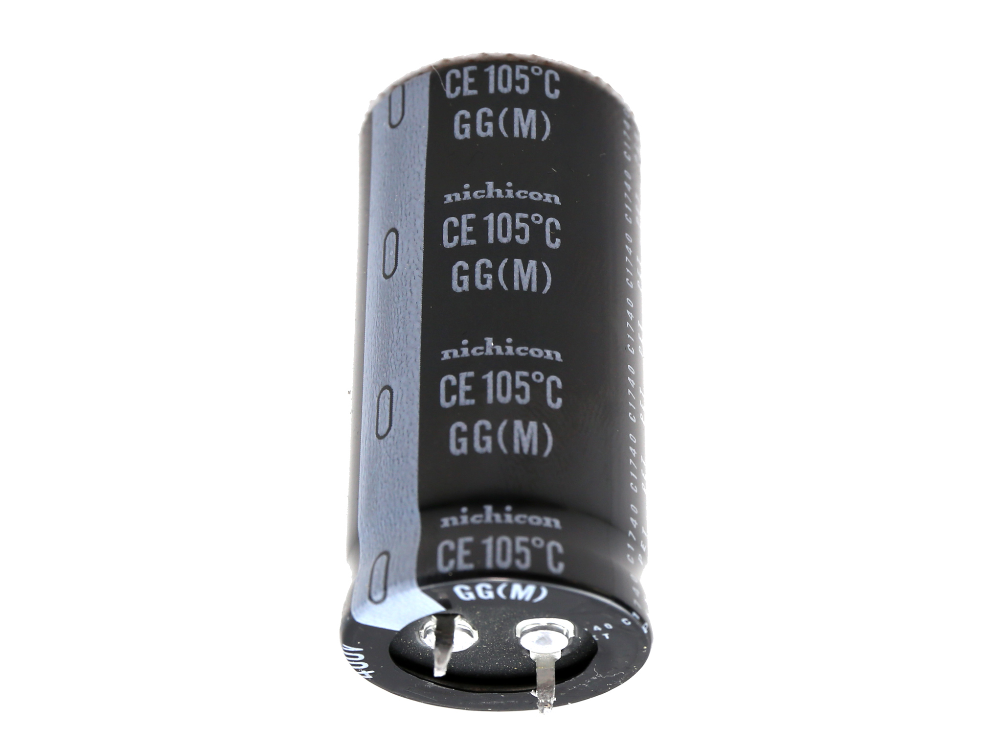
The APFC converter uses two Infineon IPA60R125C6 FETs and a CREE C3D08060A boost diode. On the solder side of the main PCB we also find a SPN5003 FET which minimizes the energy consumption while the PSU is in standby mode, by isolating the APFC converter's circuit. The bulk caps are by Nichicon (2000h @ 105°C, GG) and their combined capacity reaches 940uF, which is more than enough to offer a longer than 17ms hold-up time.
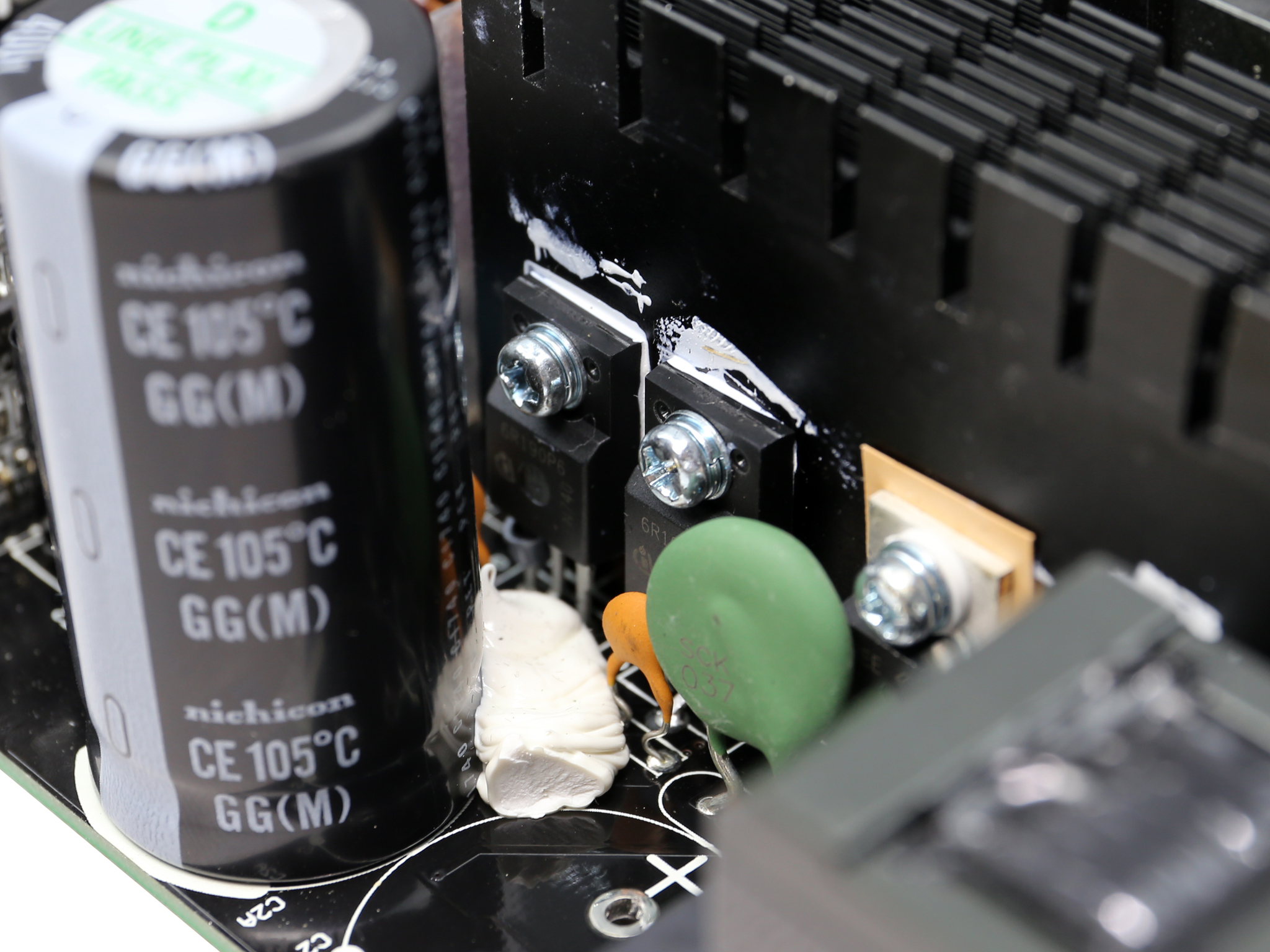
The primary switching FETs are two Infineon IPA60R190P6, arranged into a half-bridge topology. An LLC resonant converter is also used to minimize the switching energy losses.
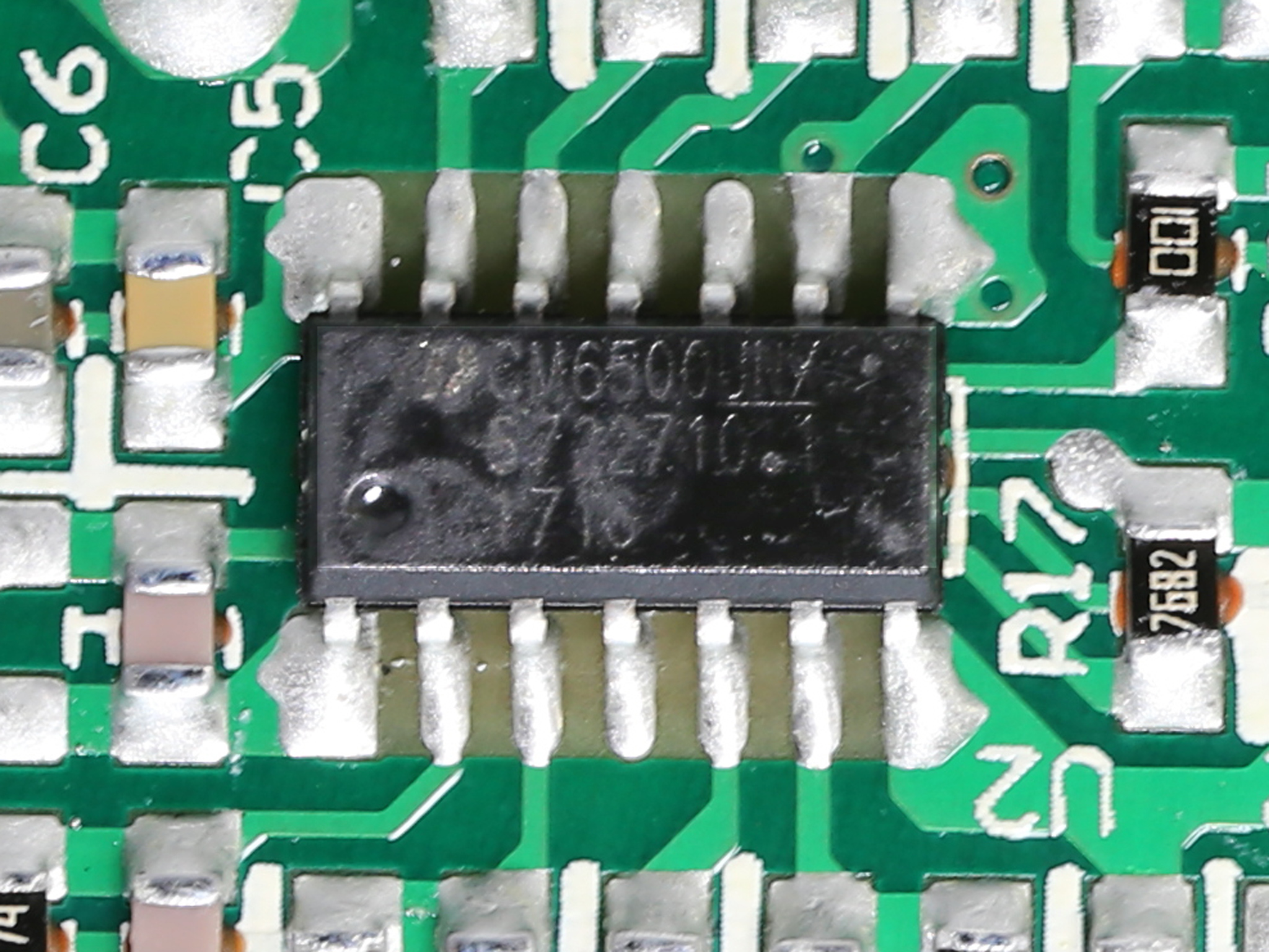
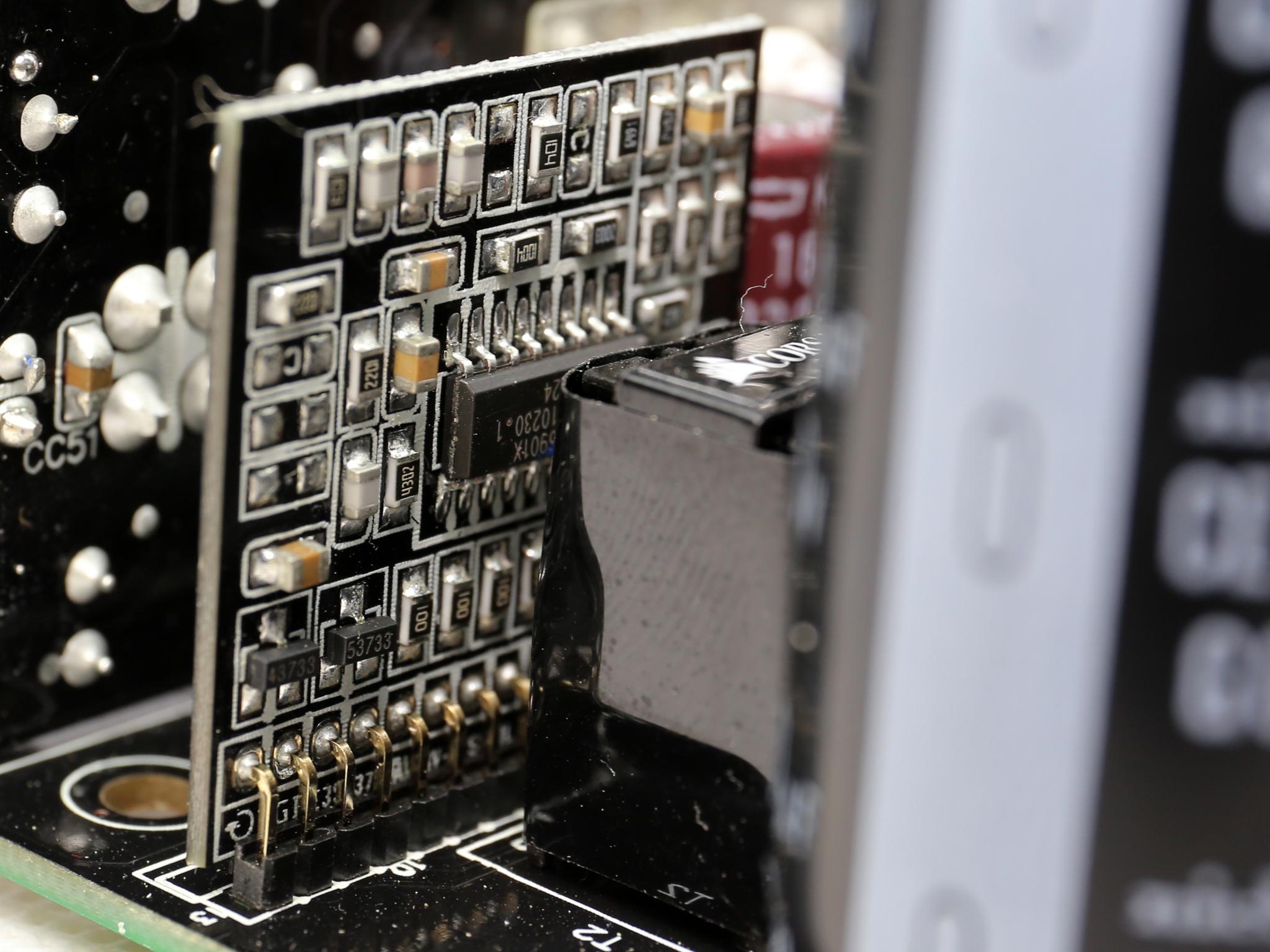
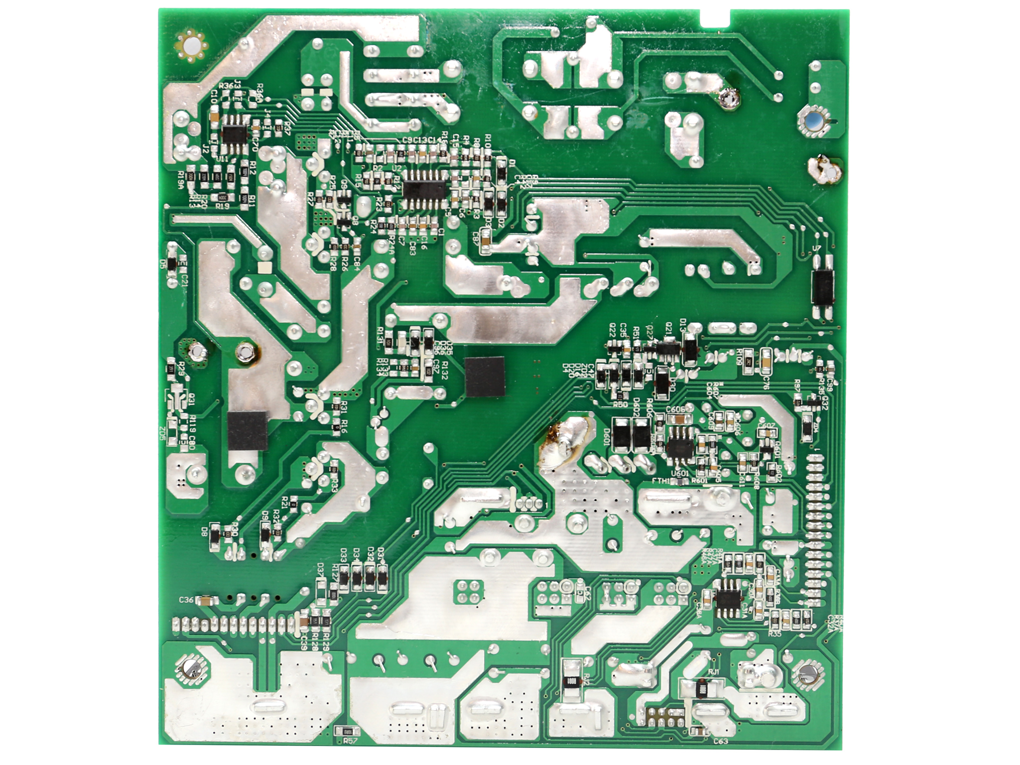
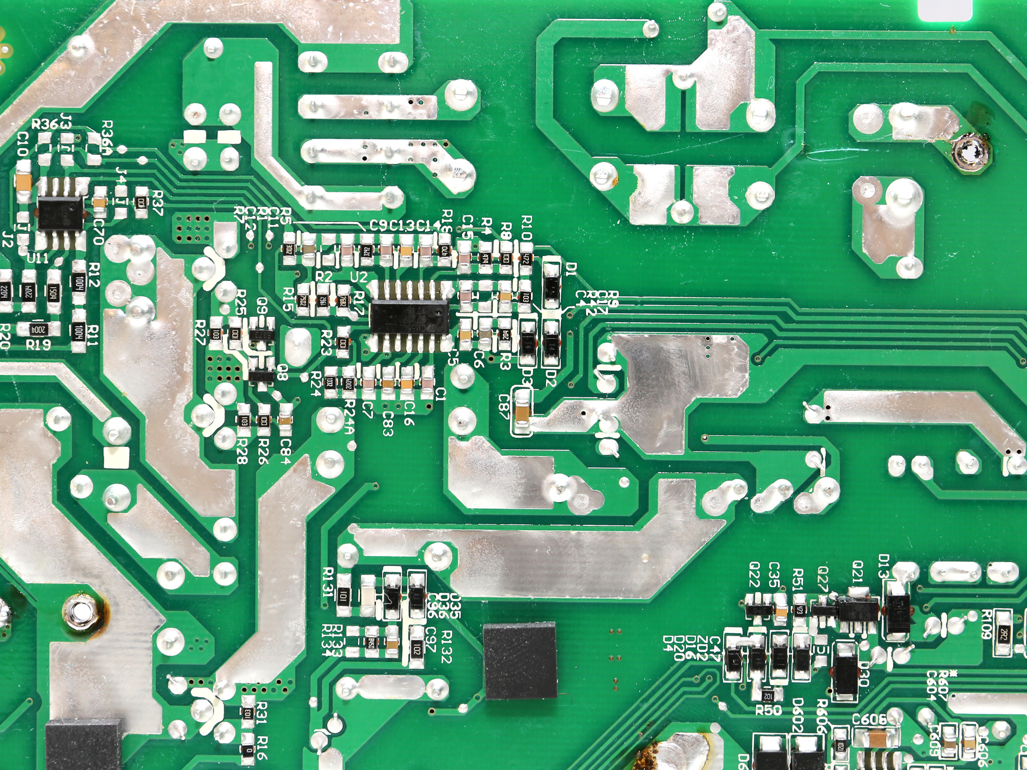
Both the APFC and LLC resonant controllers are provided by Champion and are installed at the PCB's back side. The first is a CM6500UNX and the second the famous CM6901.
![]()
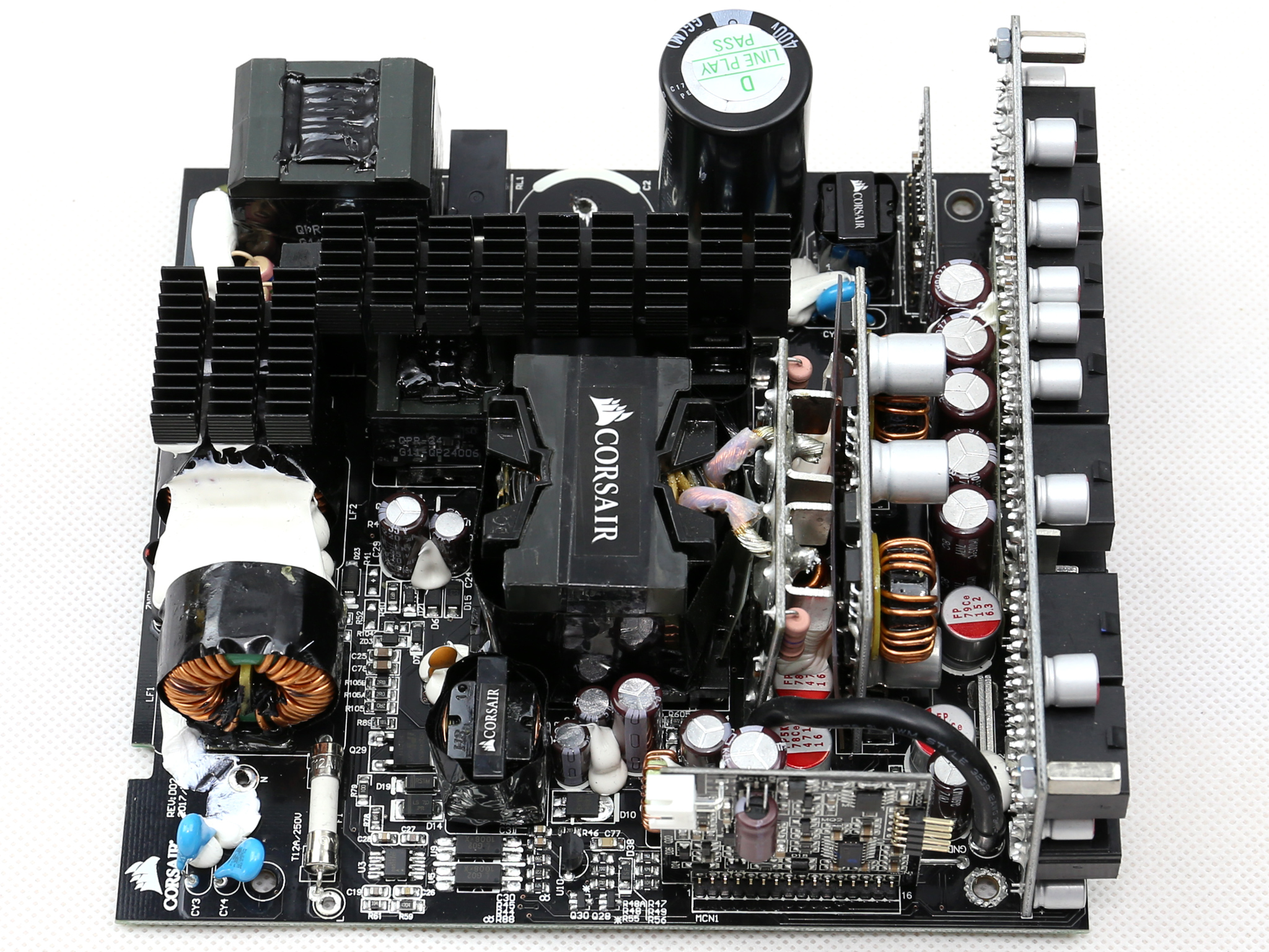
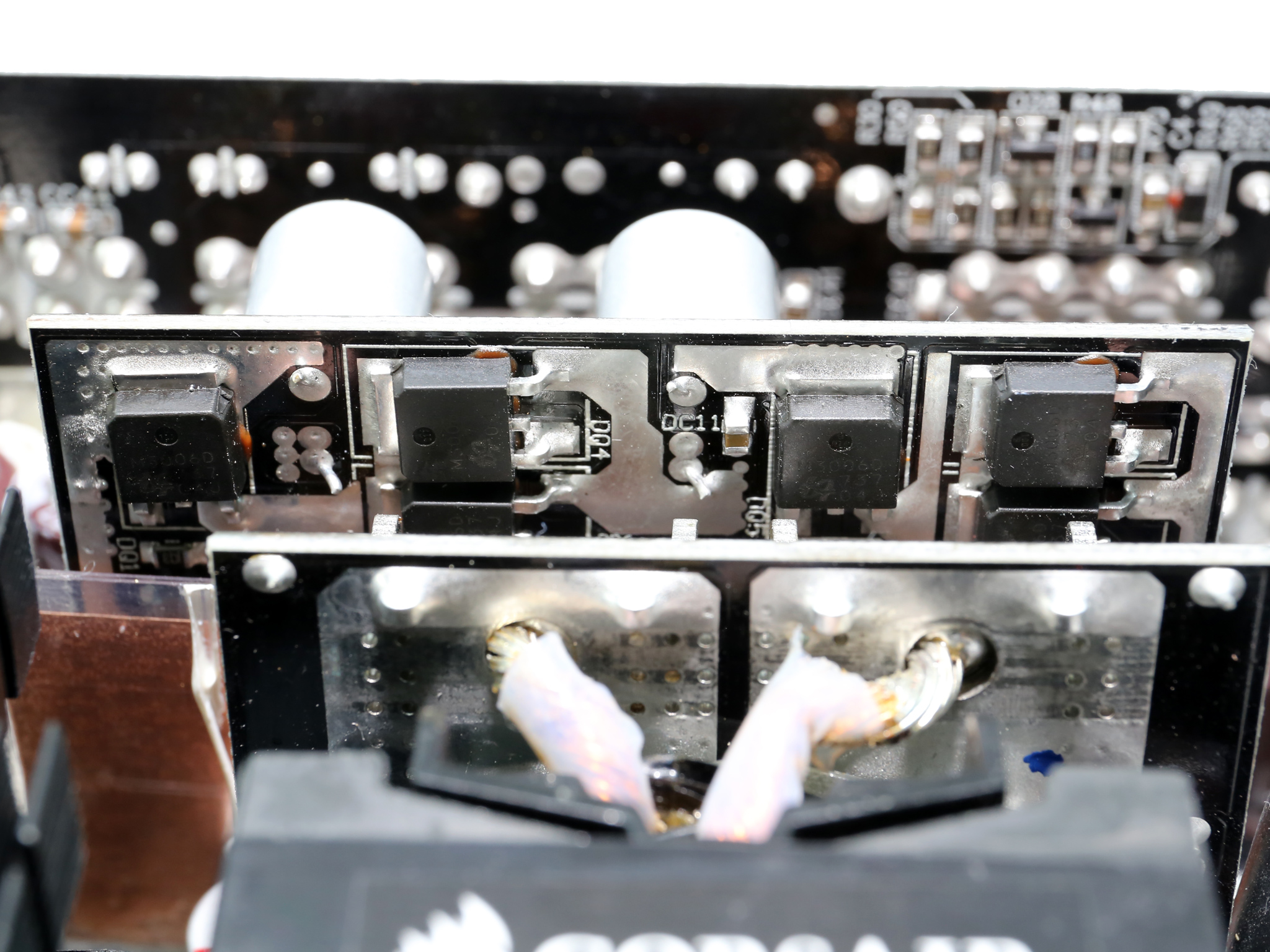
The main transformer is installed close to the board hosting the +12V FETs, in order to restrict energy losses. In some platforms the main transformer is directly soldered onto the +12V board for the same purpose.
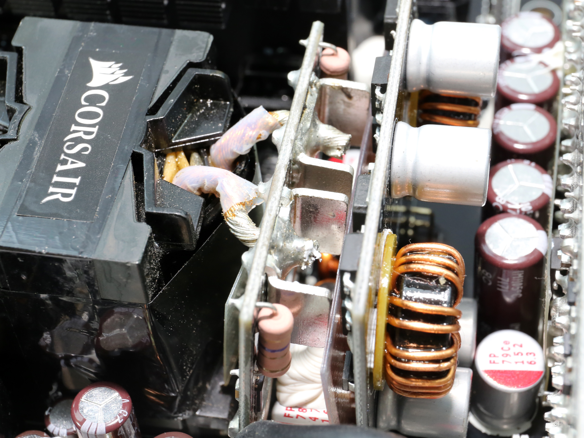
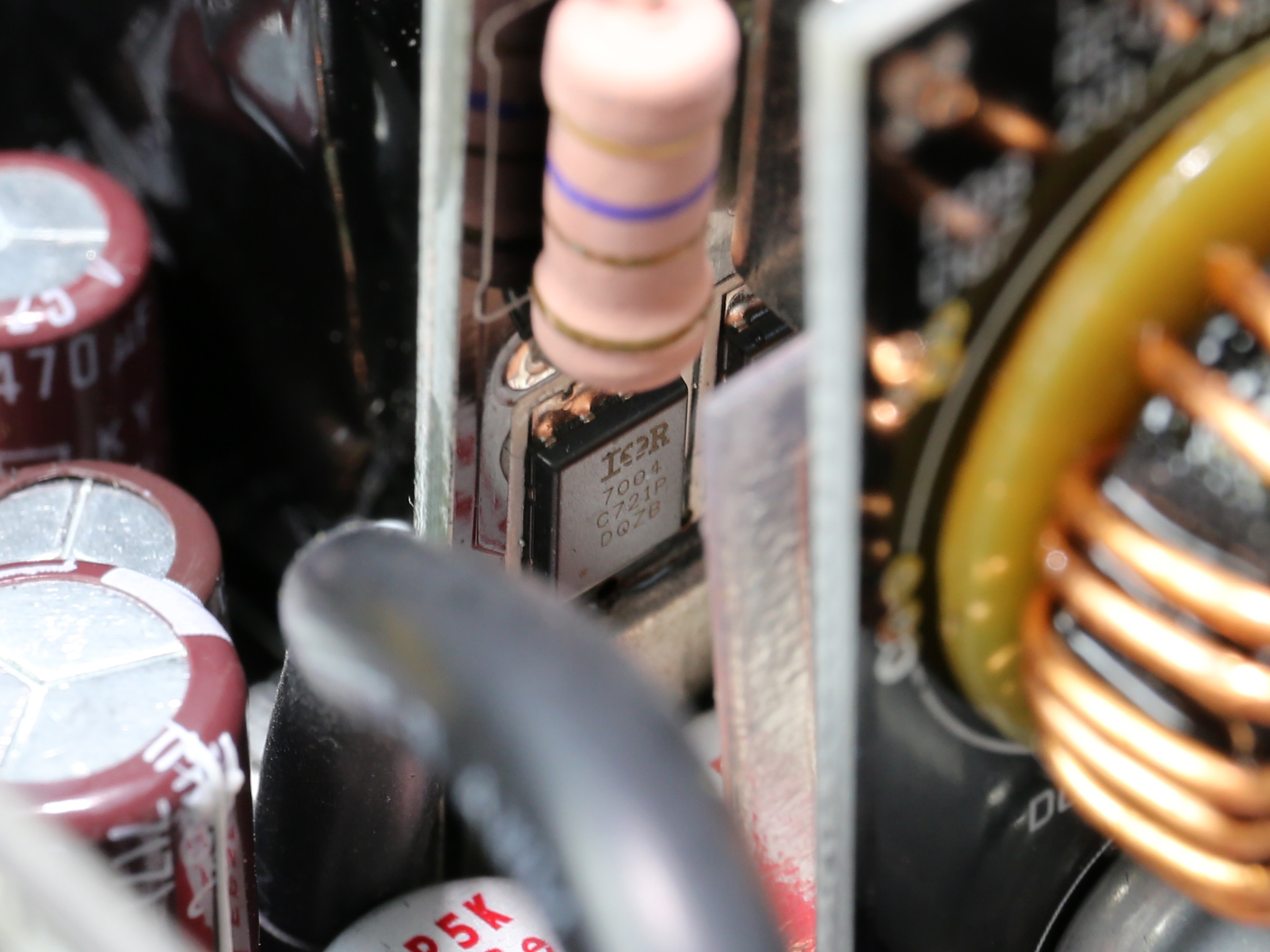
Six International Rectifier IRFH7004TRPBF FETs regulate the +12V rail. They are cooled by a number of small bus bars.
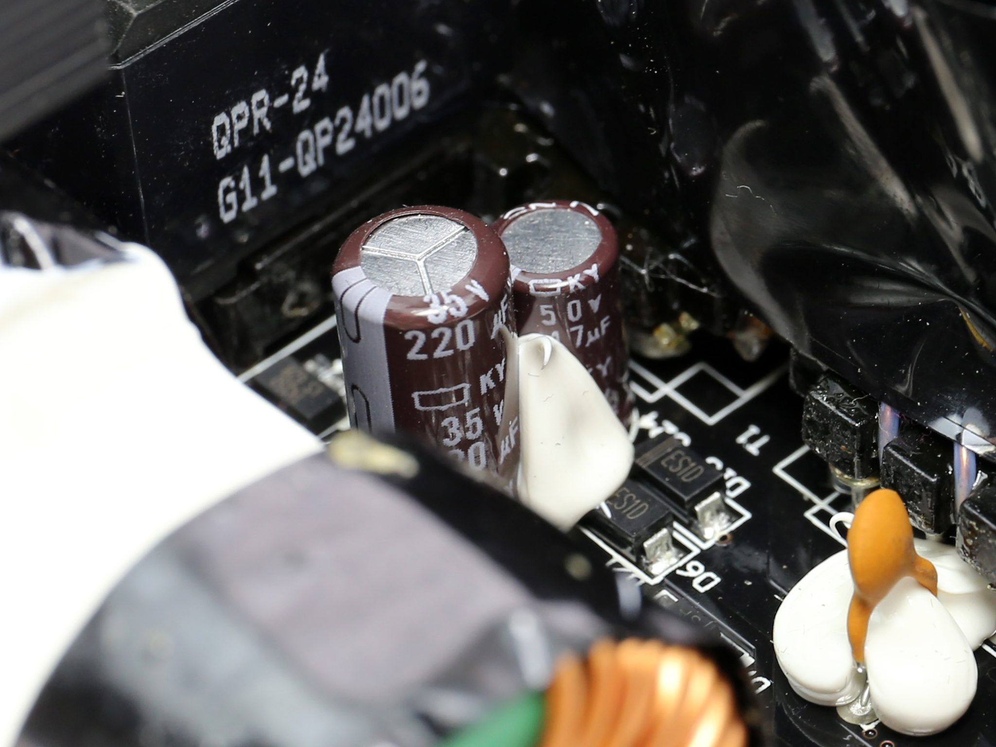
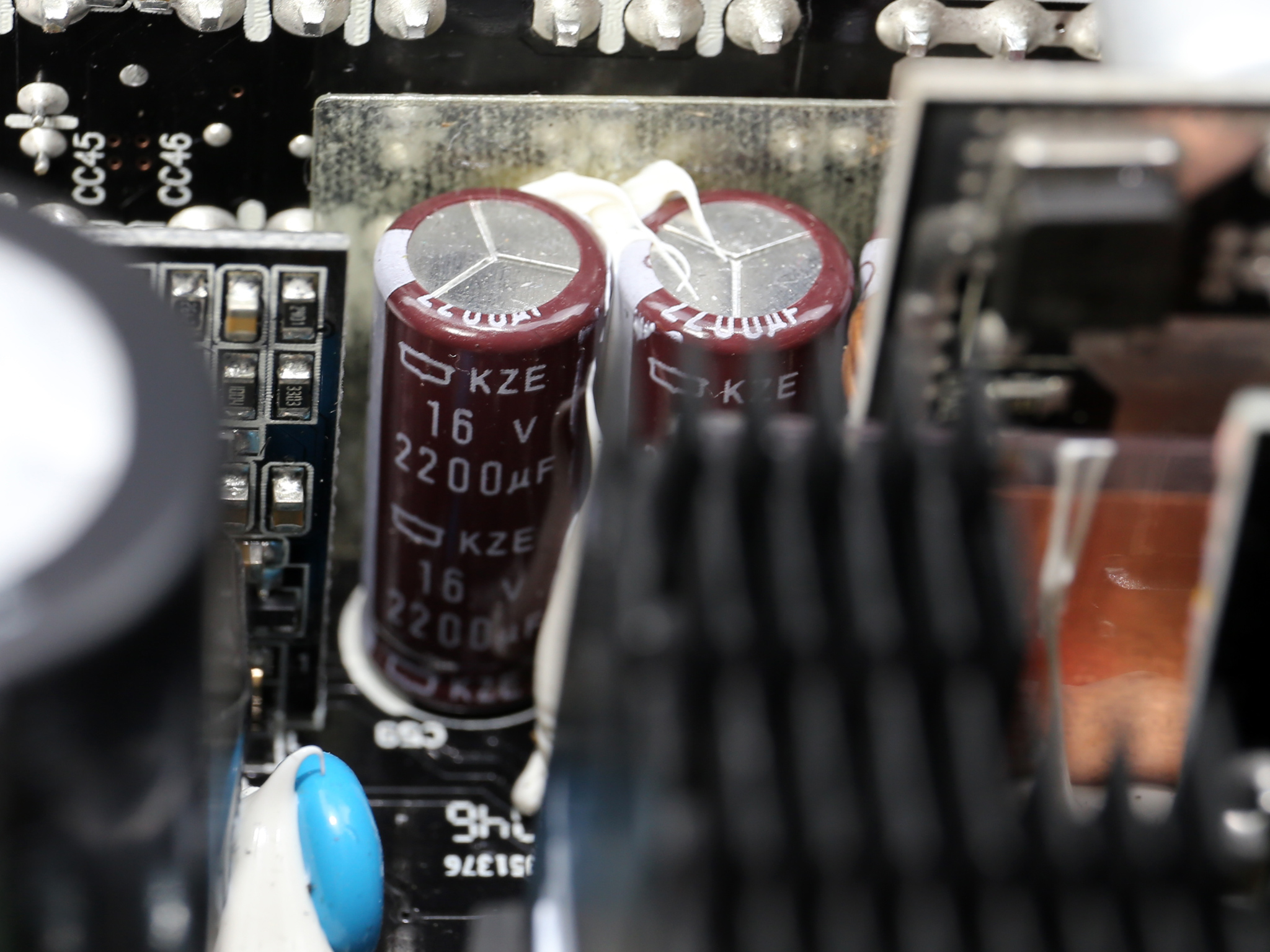
The electrolytic filtering caps are provided by Chemi-Con and belong to its mainstream KZE and the higher-end KY lines. A number of polymer FPCAPs caps is also used, for the +12V and the minor rails.

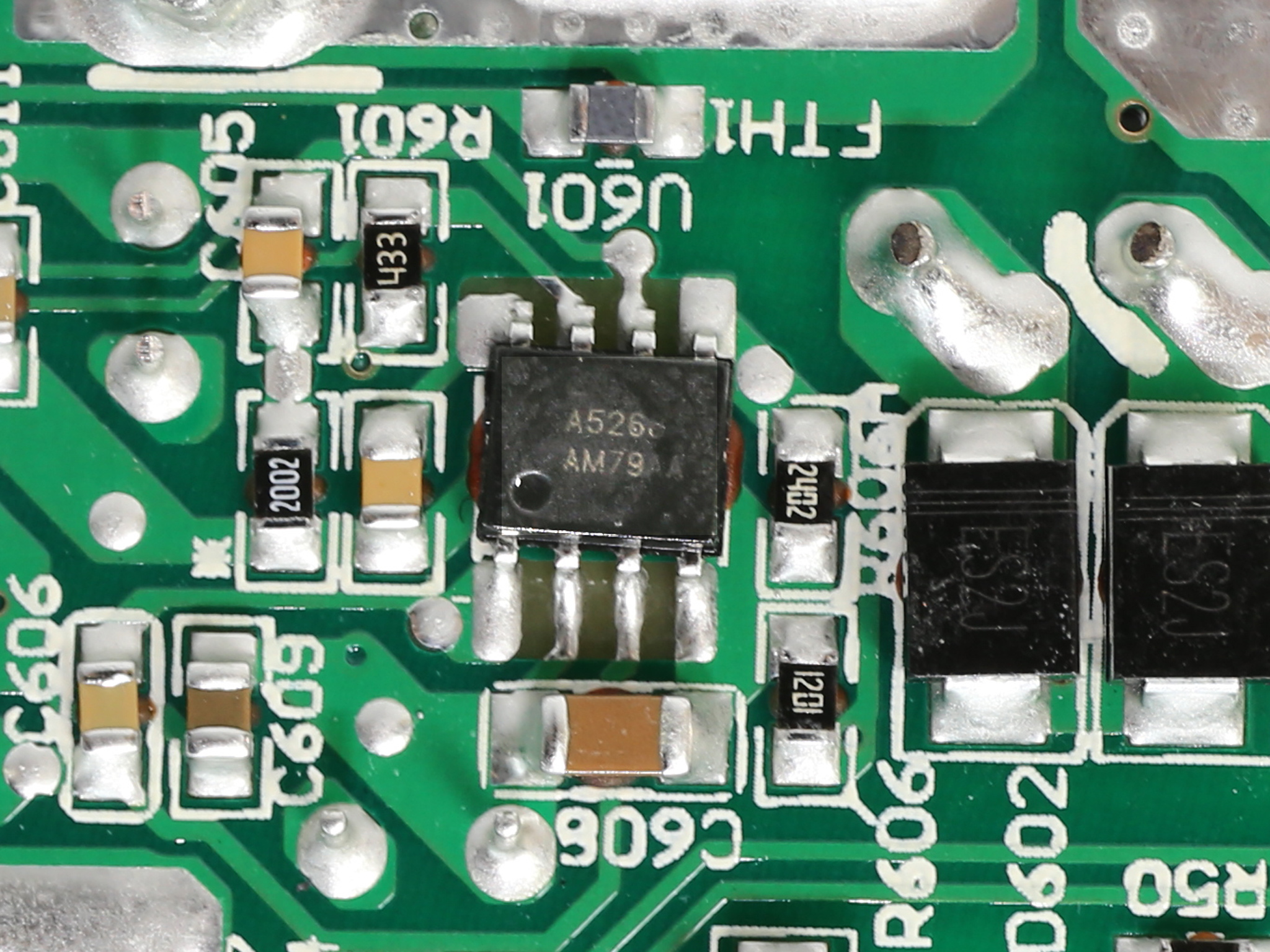
The voltage regulation modules that generate the minor rails consist of six QM3006D FETs. The common PWM controller is a ANPEC APW7159.
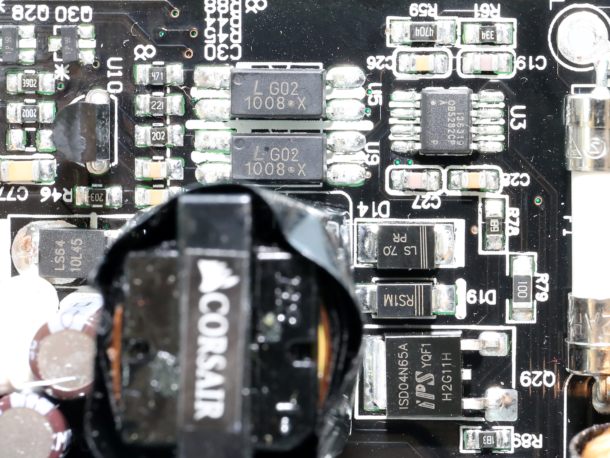
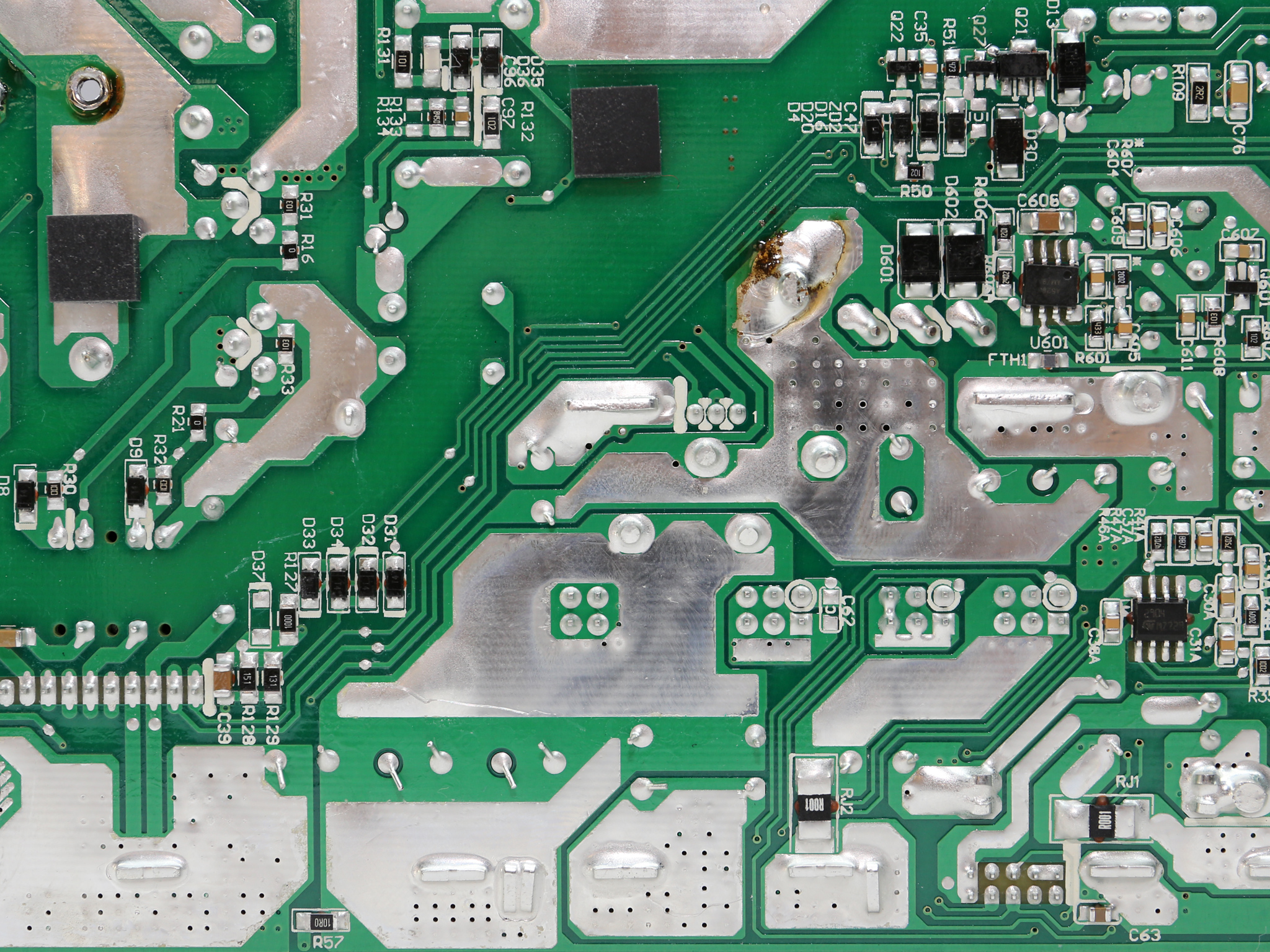
The 5VSB circuit uses an increased number of components: a ISD04N65A SBR, a QM3004D FET, a 10L45 SBR and a AME5268 step-down converter. The standby PWM controller is a On-Bright OB5269CP.
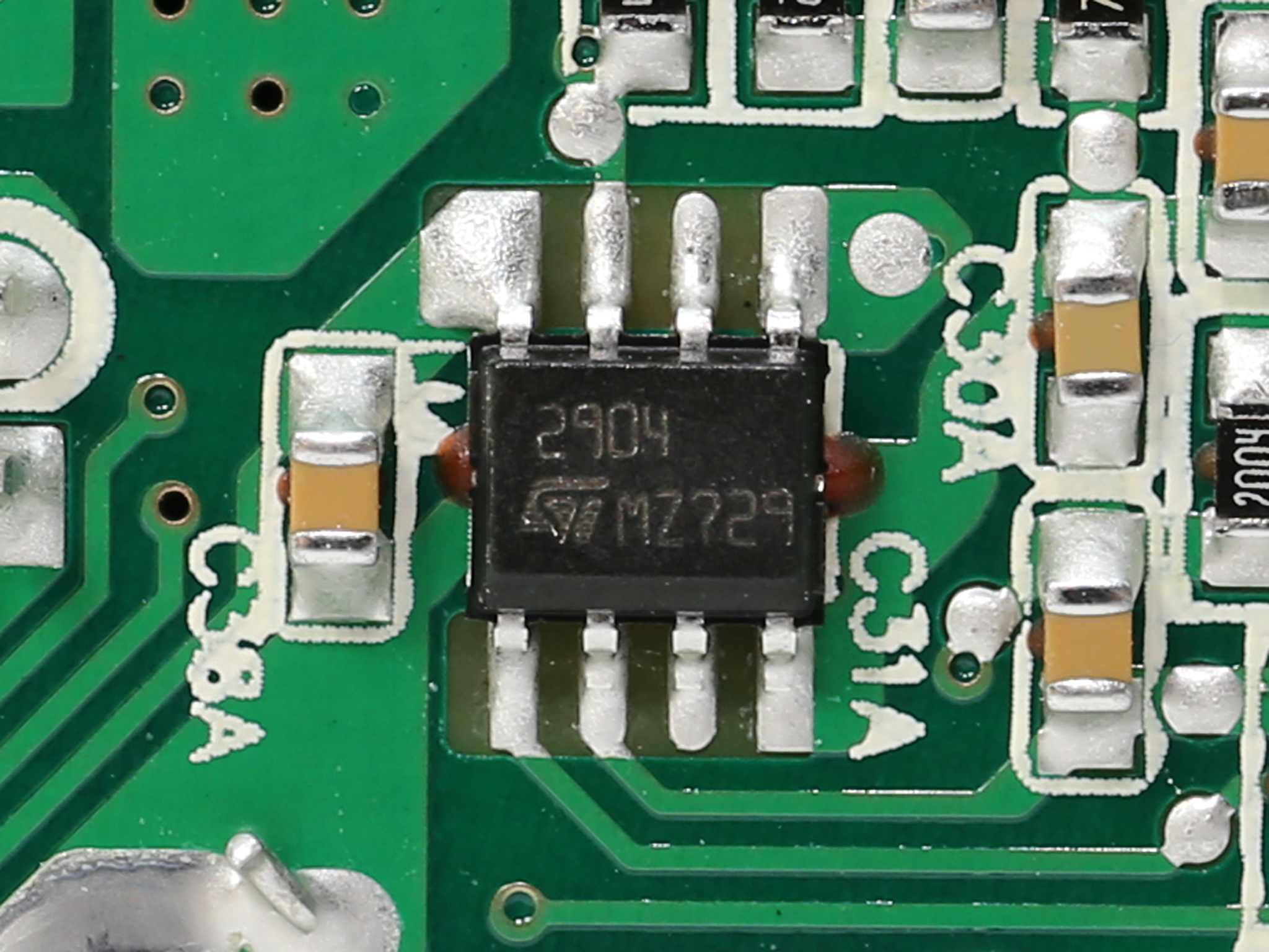
The supervisor IC is a Weltrend WT7502 which is supported by a LM393G dual differential comparator.
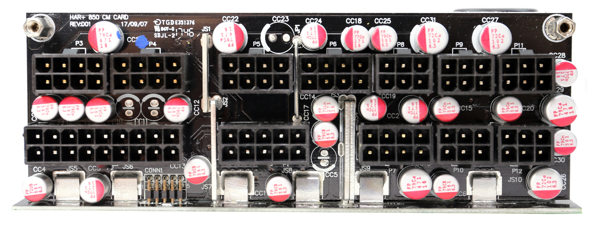
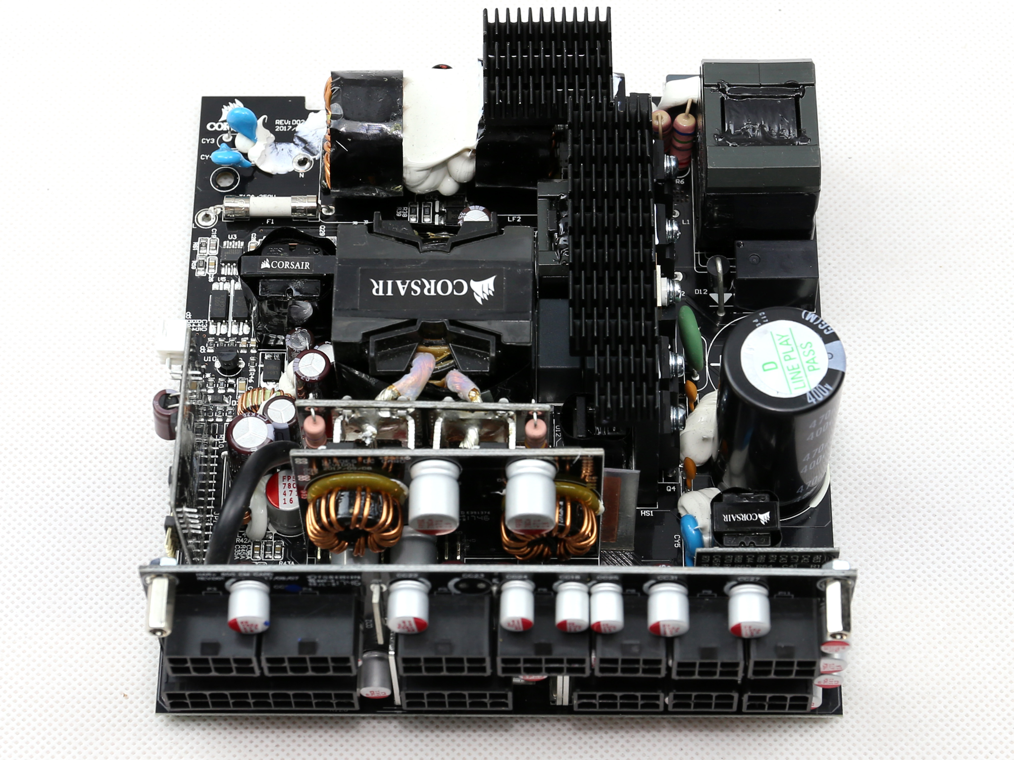
At the front side of the modular board a large number of polymer FPCAPs provides an extra ripple suppression layer.
The soldering quality is good, with proper solder joints. On top of that we didn't spot any super long component leads. The only problem here is the lead-free solder, which unfortunately is mandatory for any product sold in the EU (and not only).
This type of solder is of the worst kind to work with, demanding much higher temperatures which can damage sensitive components, and besides that it can go bad after some time. It can also easier break/crack than the solder containing lead. Because of the increased RMA rates due to the lead-free soldering, its initial purpose for a cleaner environment goes south.
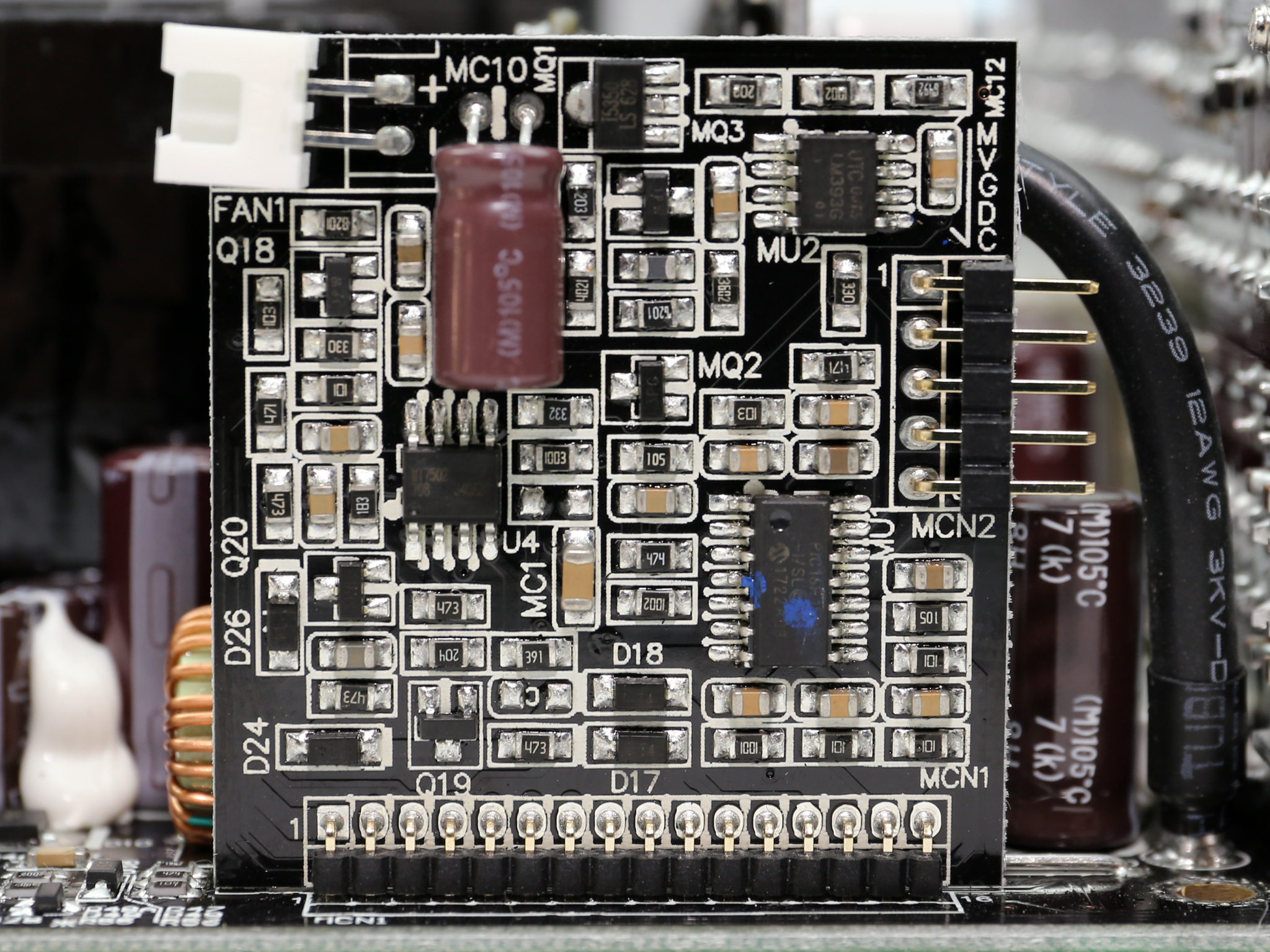
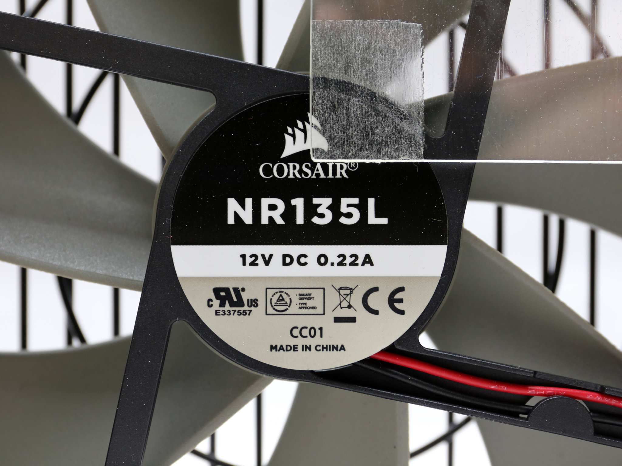
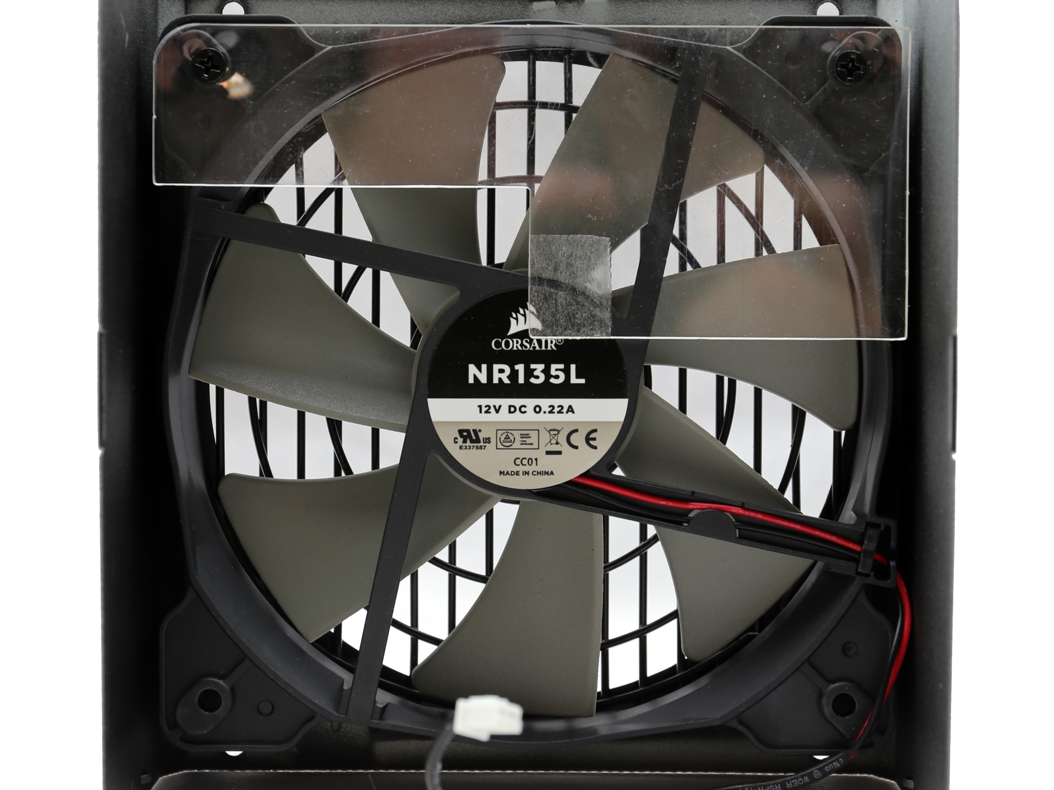
The fan controller is a Microchip PIC16F1503 and the rifle-bearing NR135L fan is also used in the new RMx units. There was no reason to change the fan after all, since it does a great job and it is reliable enough to outlive the ten-year warranty period.
To learn more about our PSU tests and methodology, please check out How We Test Power Supply Units.
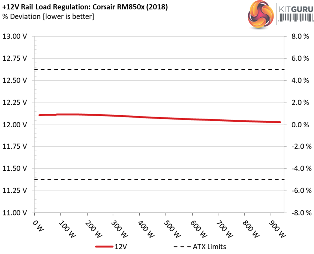
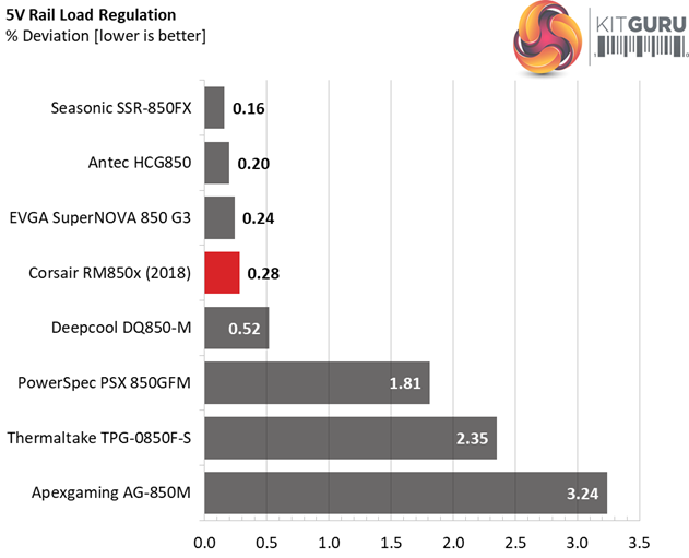
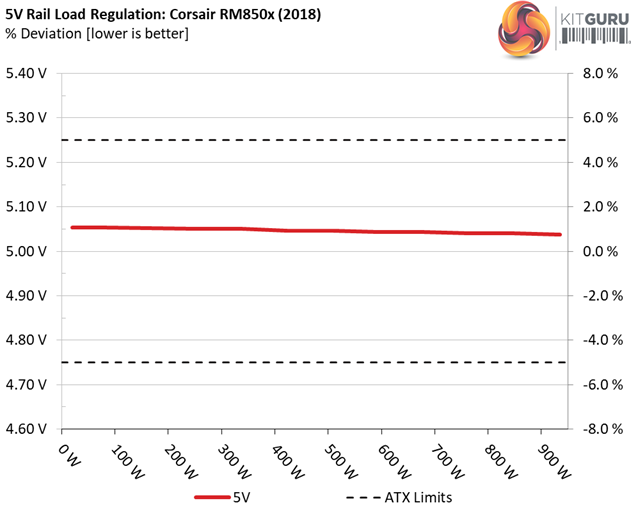
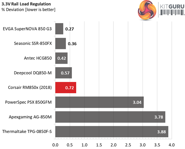
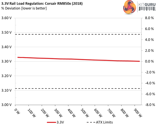
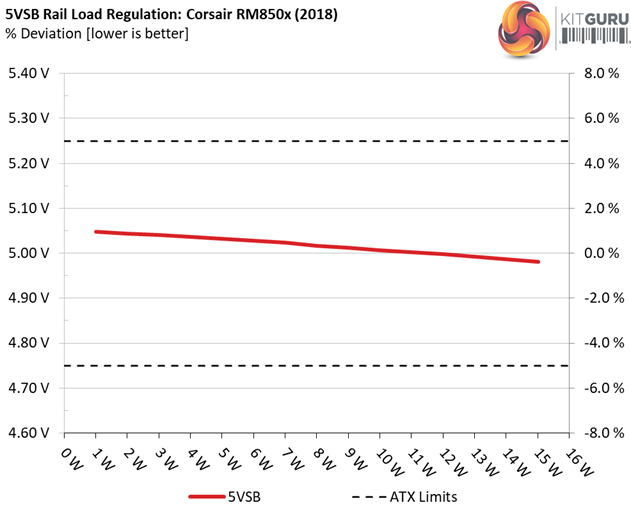
Primary Rails And 5VSB Load Regulation
Load Regulation testing is detailed here.
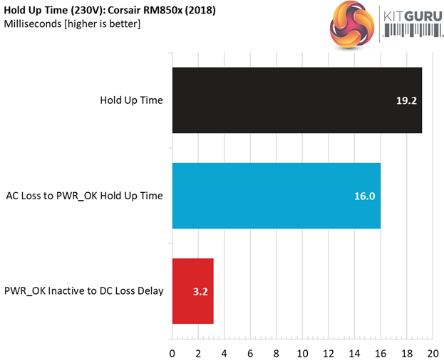
Hold-Up Time
Our hold-up time tests are described in detail here.
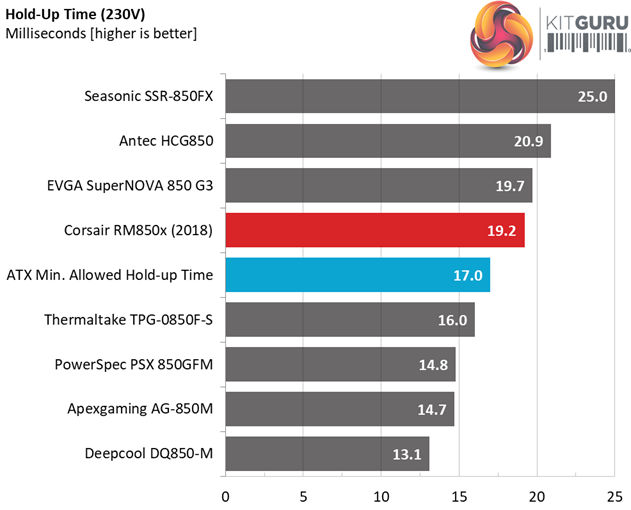
The oscilloscope screenshots that we took during the hold-up time measurements:
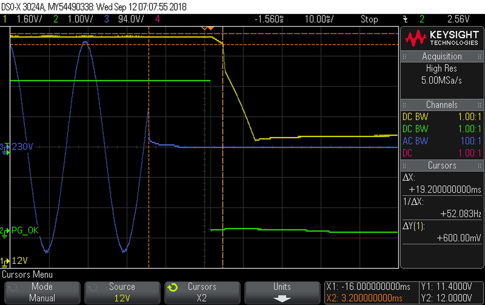
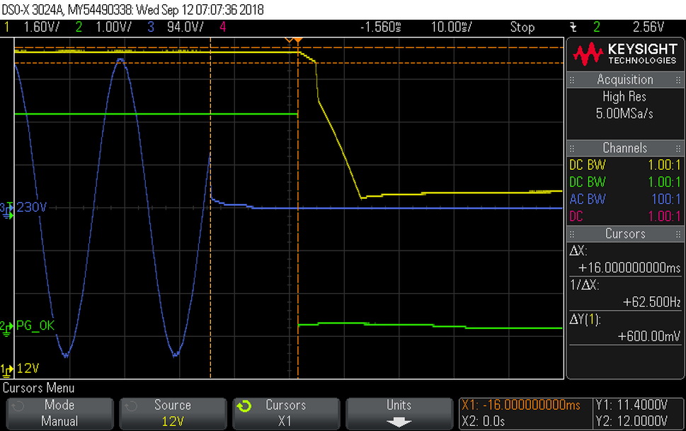
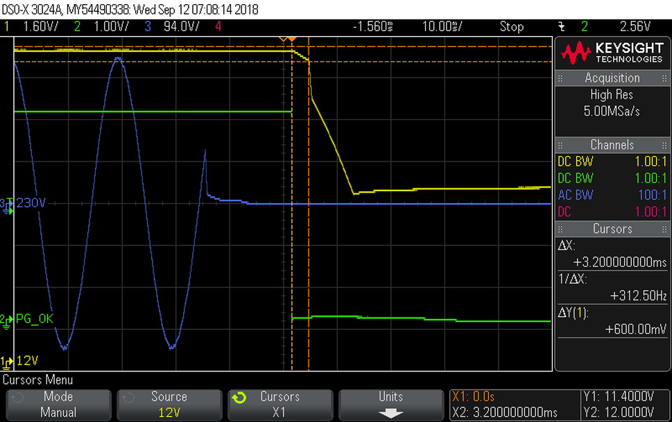
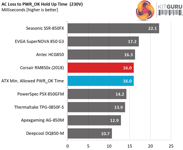
The hold-up time is longer than 17ms and the power-ok signal is accurate and right on spot, at 16ms.
Inrush Current
For details on our inrush current testing, please click here.
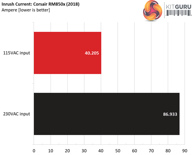
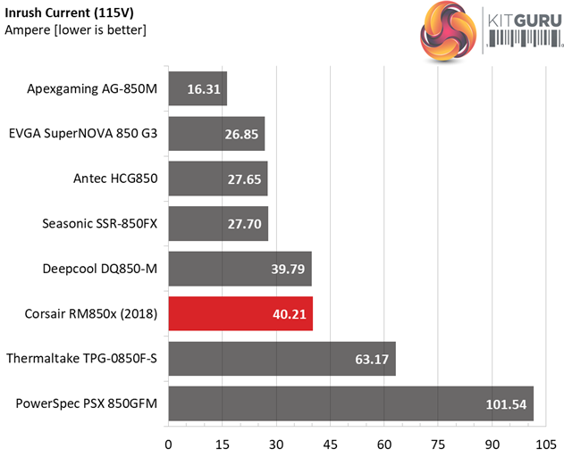
The inrush current is quite high with both voltage inputs, especially with 230V.
Load Regulation And Efficiency Measurements
The first set of tests reveals the stability of the voltage rails and the RM850x’s efficiency. The applied load equals (approximately) 10 to 110 percent of the power supplies maximum load in increments of 10 percentage points.
We conducted two additional tests.
During the first, we stressed the two minor rails (5V and 3.3V) with a high load, while the load at +12V was only 0.1A. This test reveals whether a power supply is compatible with Intel’s C6/C7 sleep states or not. In the second test, we determined the maximum load the +12V rail could handle with minimal load on the minor rails.
| Test # | 12V | 5V | 3.3V | 5VSB | DC/AC (Watts) | Efficiency | Fan Speed (RPM) | PSU Noise (dB[A]) | Temps (In/Out) | PF/AC Volts |
| 1 | 5.225A | 1.980A | 1.985A | 0.994A | 84.913 | 86.974% | 0 | <6.0 | 47.19°C | 0.970 |
| 12.115V | 5.054V | 3.326V | 5.032V | 97.630 | 40.12°C | 115.05V | ||||
| 2 | 11.434A | 2.970A | 2.977A | 1.194A | 169.435 | 90.199% | 0 | <6.0 | 48.54°C | 0.985 |
| 12.116V | 5.052V | 3.323V | 5.028V | 187.846 | 40.99°C | 115.05V | ||||
| 3 | 18.046A | 3.466A | 3.464A | 1.394A | 254.532 | 91.416% | 0 | <6.0 | 49.23°C | 0.991 |
| 12.109V | 5.051V | 3.321V | 5.023V | 278.433 | 41.17°C | 115.05V | ||||
| 4 | 24.673A | 3.962A | 3.978A | 1.595A | 339.754 | 91.411% | 0 | <6.0 | 50.97°C | 0.988 |
| 12.100V | 5.050V | 3.318V | 5.017V | 371.676 | 41.78°C | 115.05V | ||||
| 5 | 30.991A | 4.955A | 4.977A | 1.796A | 425.070 | 90.984% | 610 | 10.2 | 41.98°C | 0.989 |
| 12.086V | 5.047V | 3.316V | 5.012V | 467.194 | 51.88°C | 115.05V | ||||
| 6 | 37.258A | 5.948A | 5.977A | 1.998A | 509.599 | 90.471% | 610 | 10.2 | 42.61°C | 0.990 |
| 12.072V | 5.046V | 3.313V | 5.007V | 563.272 | 53.01°C | 115.05V | ||||
| 7 | 43.589A | 6.942A | 6.978A | 2.200A | 594.887 | 89.808% | 610 | 10.2 | 43.30°C | 0.991 |
| 12.062V | 5.044V | 3.310V | 5.002V | 662.398 | 54.30°C | 115.05V | ||||
| 8 | 49.928A | 7.935A | 7.982A | 2.402A | 680.257 | 88.988% | 888 | 22.2 | 43.90°C | 0.993 |
| 12.054V | 5.043V | 3.308V | 4.998V | 764.437 | 55.60°C | 115.04V | ||||
| 9 | 56.673A | 8.434A | 8.472A | 2.402A | 765.203 | 88.194% | 1130 | 30.3 | 44.46°C | 0.994 |
| 12.046V | 5.041V | 3.305V | 4.998V | 867.641 | 56.50°C | 115.04V | ||||
| 10 | 63.158A | 8.931A | 8.994A | 3.013A | 850.023 | 87.226% | 1415 | 36.7 | 46.20°C | 0.995 |
| 12.038V | 5.040V | 3.303V | 4.981V | 974.511 | 58.61°C | 115.04V | ||||
| 11 | 70.244A | 8.935A | 8.998A | 3.014A | 934.759 | 86.187% | 1440 | 37.1 | 46.71°C | 0.996 |
| 12.030V | 5.038V | 3.301V | 4.979V | 1084.566 | 59.59°C | 115.03V | ||||
| CL1 | 0.146A | 18.004A | 17.999A | 0.000A | 152.460 | 81.936% | 714 | 16.5 | 41.96°C | 0.985 |
| 12.097V | 5.053V | 3.318V | 5.102V | 186.071 | 51.73°C | 115.06V | ||||
| CL2 | 70.846A | 1.000A | 1.000A | 1.000A | 866.348 | 87.734% | 1300 | 34.5 | 46.78°C | 0.995 |
| 12.040V | 5.041V | 3.306V | 5.015V | 987.473 | 58.74°C | 115.04V |
The load regulation is tight on all rails and the fan profile is super relaxed even under extremely stressful conditions. Moreover, the semi-passive operation lasts for quite long and doesn't seem to be affected by high operating temperatures. Although there are no heatsinks in the secondary side, CWT's platform doesn't seem to have any problem at all under increased temperatures.
The 80 PLUS Gold requirements with 20%, 50% and full load are easily met even with the tough conditions that we apply. This is something that we don't see everyday.
Efficiency
Our efficiency testing procedure is detailed here.
Using results from the previous page, we plotted a chart showing the RM850x’s efficiency at low loads, and loads from 10 to 110 percent of its maximum-rated capacity.
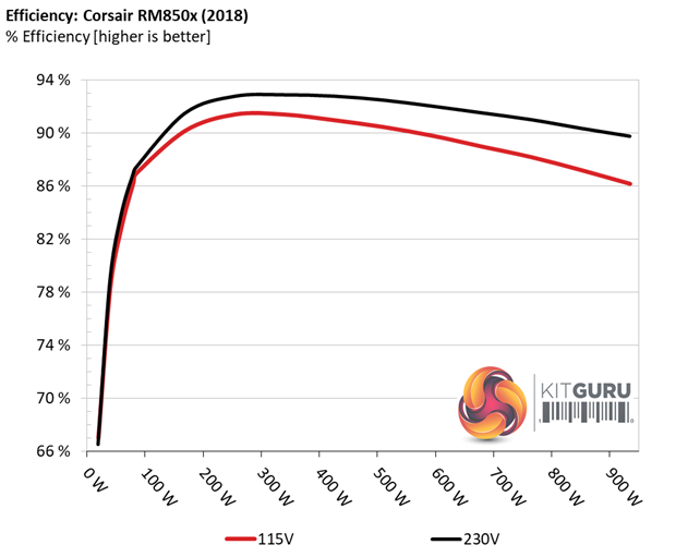
With normal loads the RM850x takes over the second place while with light loads it falls a little behind.
Efficiency At Low Loads
In the following tests, we measure the RM850x's efficiency at loads significantly lower than 10 percent of its maximum capacity (the lowest load the 80 PLUS standard measures). The loads we dial are 20, 40, 60, and 80W. This is important for representing when a PC is idle, with power-saving features turned on.
| Test # | 12V | 5V | 3.3V | 5VSB | DC/AC (Watts) | Efficiency | Fan Speed (RPM) | PSU Noise (dB[A]) | PF/AC Volts |
| 1 | 1.194A | 0.495A | 0.482A | 0.198A | 19.562 | 67.048% | 0 | <6.0 | 0.874 |
| 12.108V | 5.053V | 3.328V | 5.048V | 29.176 | 115.05V | ||||
| 2 | 2.451A | 0.989A | 0.991A | 0.397A | 39.984 | 78.325% | 0 | <6.0 | 0.936 |
| 12.112V | 5.053V | 3.327V | 5.044V | 51.049 | 115.05V | ||||
| 3 | 3.638A | 1.484A | 1.474A | 5.041A | 59.472 | 82.943% | 0 | <6.0 | 0.961 |
| 12.114V | 5.053V | 3.327V | 5.041V | 71.702 | 115.05V | ||||
| 4 | 4.897A | 1.979A | 1.986A | 0.794A | 79.922 | 86.304% | 0 | <6.0 | 0.966 |
| 12.113V | 5.053V | 3.326V | 5.037V | 92.605 | 115.05V |
It would be ideal if the registered efficiency with 20W load was closer or over 70%, while with 40W we would like to see above 80%. In all four light-load tests the PSU's fan is not engaged. It needs much higher loads (and temperatures), for the fan to start spinning.
5VSB Efficiency
The ATX specification (revision 1.4), along with CEC, ErP Lot 3 2014 and ErP Lot 6 2010/2013, states that the 5VSB standby supply efficiency should be as high as possible, recommending 75 percent or higher with 550mA, 1A, and 1.5A of load.
The supply should also achieve higher than 75% efficiency at 5VSB under full load, or with 3A if its max current output on this rail is higher than 3A.
We take six measurements: one each at 100, 250, 550, 1000, and 1500mA, and one with the full load the 5VSB rail can handle.
| Test # | 5VSB | DC/AC (Watts) |
Efficiency | PF/AC Volts |
| 1 | 0.100A | 0.505 | 75.940% | 0.062 |
| 5.047V | 0.665 | 115.05V | ||
| 2 | 0.250A | 1.261 | 78.080% | 0.141 |
| 5.043V | 1.615 | 115.05V | ||
| 3 | 0.550A | 2.769 | 78.822% | 0.251 |
| 5.033V | 3.513 | 115.06V | ||
| 4 | 1.000A | 5.021 | 78.124% | 0.340 |
| 5.020V | 6.427 | 115.06V | ||
| 5 | 1.500A | 7.510 | 77.775% | 0.391 |
| 5.006V | 9.656 | 115.06V | ||
| 6 | 3.000A | 14.897 | 76.258% | 0.453 |
| 4.965V | 19.535 | 115.06V |
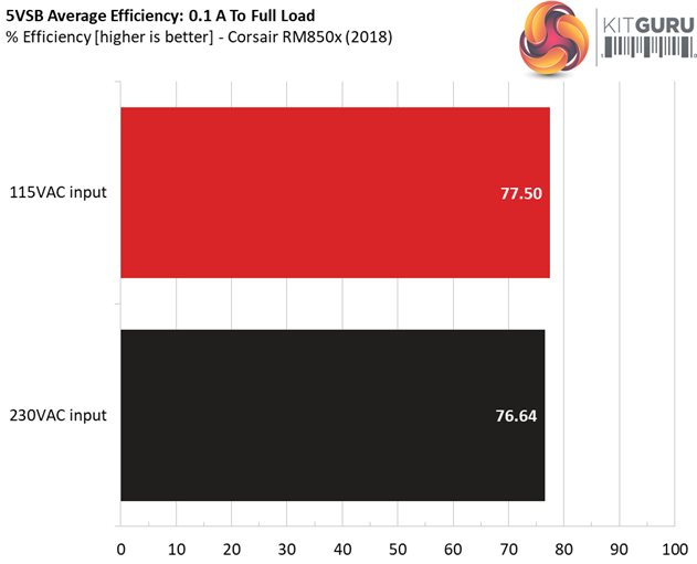
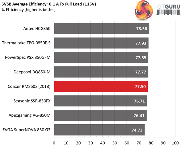
The 5VSB rail's efficiency is close to the competition but still on the low side. It would be great to see at least one reading close to 80%.
Power Consumption In Idle And Standby
In the table below, you’ll find the power consumption and voltage values of all rails (except -12V) when the PSU is idle (powered on, but without any load on its rails), and the power consumption when the unit is in standby mode (without any load, at 5VSB).
| Mode | 12V | 5V | 3.3V | 5VSB | Watts | PF/AC Volts |
| Idle | 12.101V | 5.048V | 3.326V | 5.047V | 7.912 | 0.518 |
| 115.1V | ||||||
| Standby | 0.032 | 0.003 | ||||
| 115.1V | ||||||
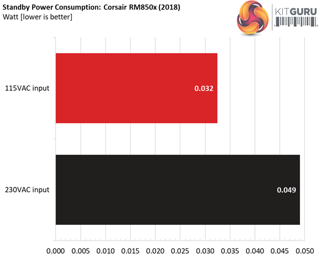
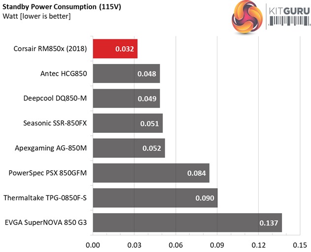
The vampire power levels are very low, with both 115V and 230V input.
Fan RPM, Delta Temperature, And Output Noise
Our mixed noise testing is described in detail here.
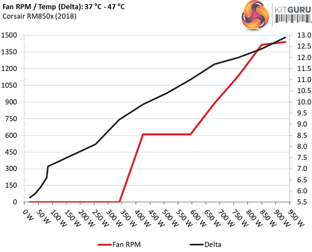
The first chart below illustrates the cooling fan's speed (in RPM), and the delta between input and output temperature. The results were obtained at 37°C (98.6°F) to 47°C (116.6°F) ambient temperature.
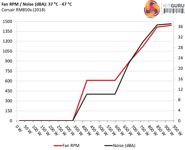
The next chart shows the cooling fan's speed (again, in RPM) and output noise. We measure acoustics from one meter away, inside a hemi-anechoic chamber. Background noise inside the chamber is below 6 dB(A) during testing (it's actually much lower, but our sound meter’s microphone hits its floor), and the results are obtained with the PSU operating at 37°C (98.6°F) to 47°C (116.6°F) ambient temperature.
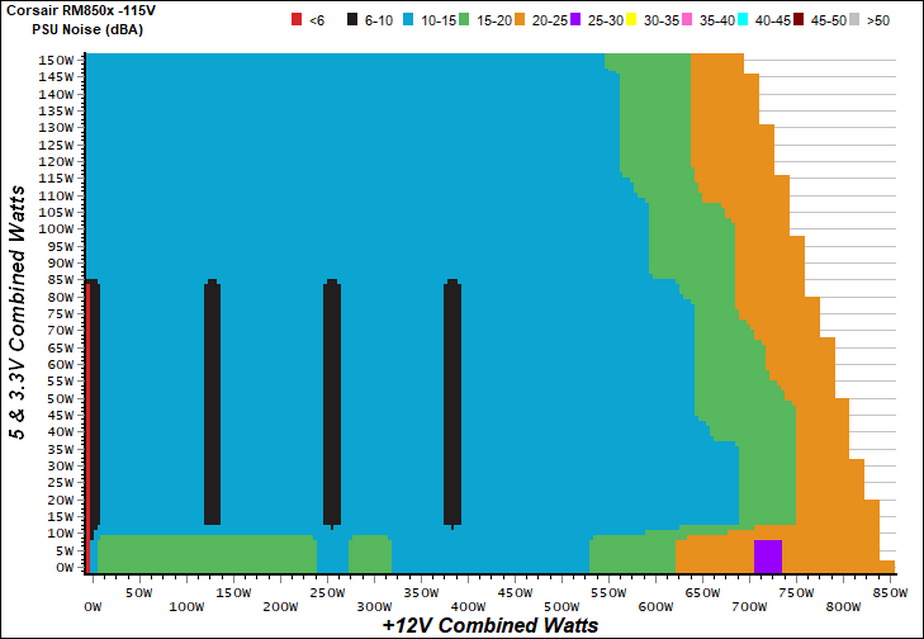
The following graph illustrates the fan's output noise over the PSU's operating range. The same conditions of the above graph apply to our measurements, though the ambient temperature is between 30°C (86°F) to 32°C (89.6°F).
Once you start pushing the minor rails the semi-passive operation ends prematurely. Nevertheless, the fan spins at very low speeds keeping the overall noise output low. Under normal operating temperatures the PSU's noise won't exceed 30 dB(A), even with prolonged full load operation.
Protection Features
Our protection features evaluation methodology is described in detail here.
|
Protection |
|
|
OCP |
12V: 90A (127.12%), 11.994V |
|
OPP |
1095.7W (128.9%) |
|
OTP |
✓ (180°C @ 12V board) |
|
SCP |
12V: ✓ |
|
PWR_OK |
Proper Operation |
|
NLO |
✓ |
|
SIP |
Surge: MOV |
The OCP and OPP triggering points are reasonable set, while the 5VSB rail is set rather high at 180% of its nominal output. Nonetheless, we don't measure increased ripple and the voltage is within the ATX spec.
As expected the over temperature protection's triggering point is set high, providing enough room for a prolonged passive operation. After all the +12V parts, which are stressed the most, are highly tolerant to increased temperatures. Finally, the power ok signal is accurate and there is short circuit protection on all rails.
DC Power Sequencing
According to Intel’s most recent Power Supply Design Guide (revision 1.4) the +12V and 5V voltages must be equal or greater than the 3.3V rail’s output at all times, during the power-up and normal operation. For our first measurement, we turn the unit off and switch it back on without any load in any of the rails.
In the second test, we set the PSU to standby mode, dial full load and start it afterwards. In the last test, while the power supply is completely switched off (we cut off the power or switch the supply off through its power switch), we dial full load before restoring power.
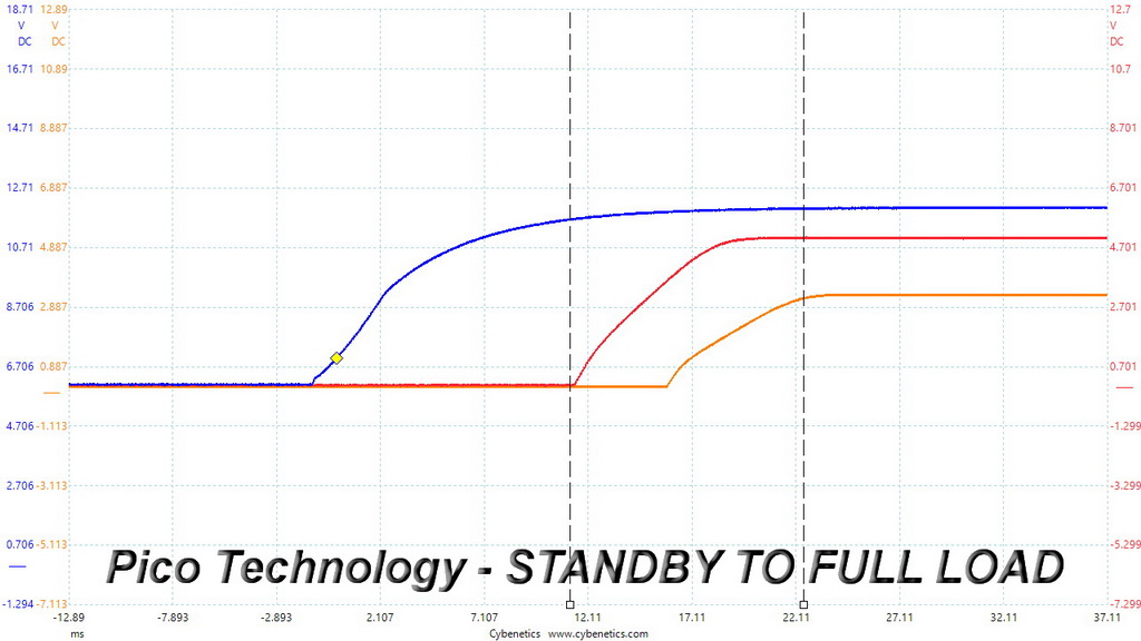
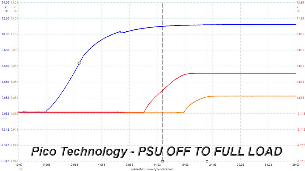
The results are perfect since in all cases the 3.3V rail's voltage is lower compared to the rest two rails and the peaks are within the 20ms range that the ATX spec requires.
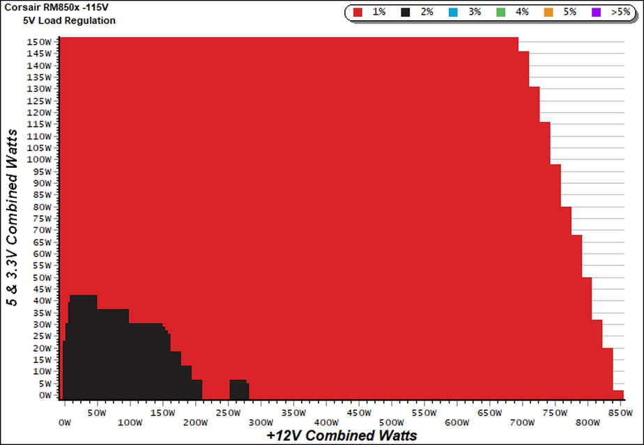
Our cross-load tests are described in detail here.
To generate the following charts, we set our loaders to auto mode through our custom-made software before trying more than 1500 possible load combinations with the +12V, 5V, and 3.3V rails. The load regulation deviations in each of the charts below are calculated by taking the nominal values of the rails (12V, 5V, and 3.3V) as point zero. The ambient temperature is between at 30°C (86°F) to 32°C (89.6°F).
Load Regulation Charts


Efficiency Chart
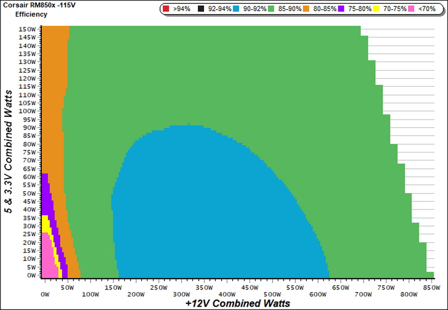
There is no region with efficiency exceeding 92%, however the 90-92% region is quite large. If the combined load on the minor rails was 100-120W, the unit's overall efficiency would be notably higher.There is no need anymore for so strong minor rails, after all.
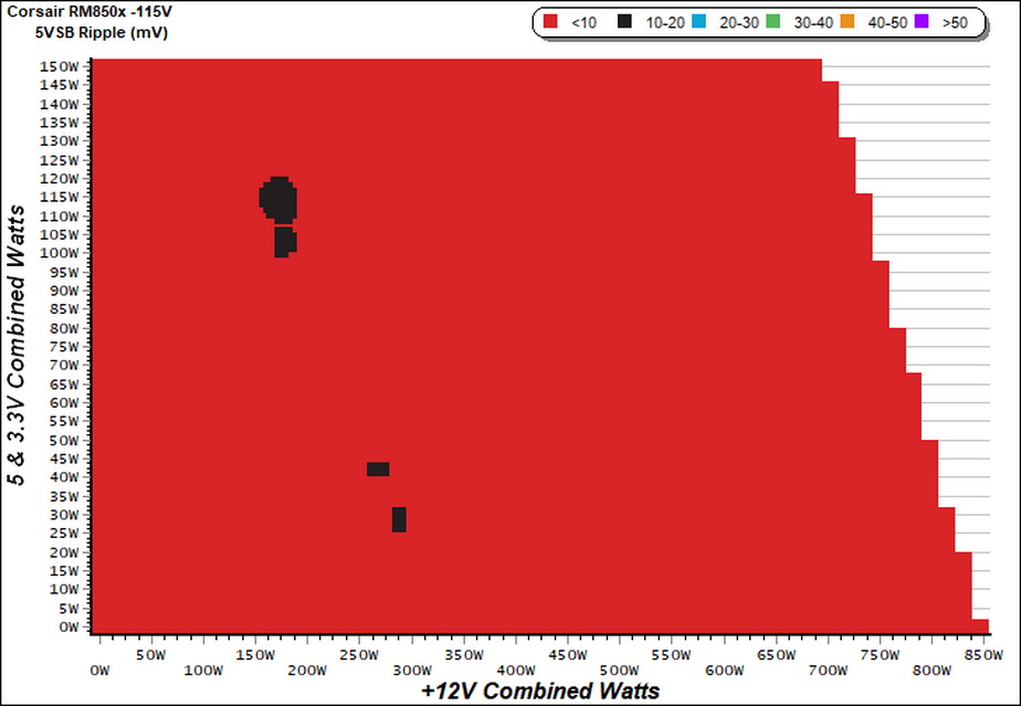
Ripple Charts


Infrared Images
We apply half-load for 10 minutes with the PSU’s top cover and cooling fan removed before taking photos with our modified FLIR E4 camera that delivers 320×240 IR resolution (76,800 pixels).
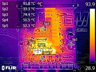
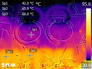
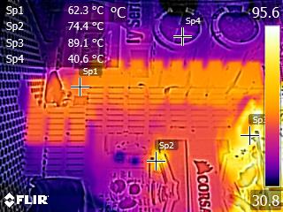
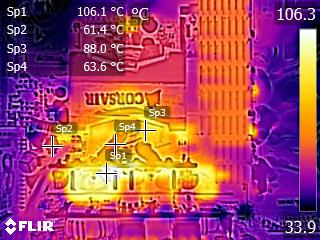
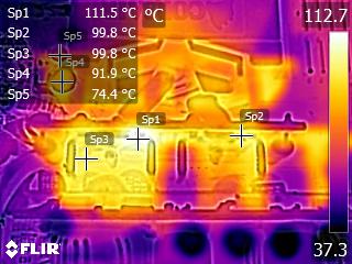
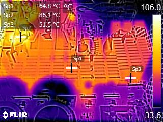
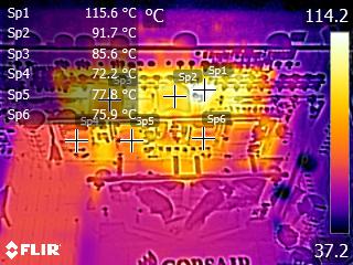
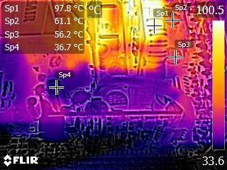
The bus bars on the +12V board get quite hot, exceeding 110°C. This is natural since we push the PSU with 425W load for ten minutes without any active cooling, so those metallic bars have to take the heat off the +12V FETs. As it seems they do a good job since those FETs stay below 80°C. The bulk caps along with the filtering caps on the secondary side don't get too hot, so most likely the prolonged passive operation in this PSU won't create any problems on the long run.
Advanced Transient Response Tests
For details on our transient response testing, please click here.
These tests are crucial because they simulate the transient loads a PSU is likely to handle (such as booting a RAID array or an instant 100 percent load of CPU/GPUs). We call these “Advanced Transient Response Tests” and they are designed to be very tough to master, especially for a PSU with a capacity of less than 500W.
In all of the tests, we use an oscilloscope to measure the voltage drops caused by the transient load. The voltages should remain within the ATX specification's regulation limits.
We should note that the ATX spec requires for capacitive loading during the transient rests, but in our methodology we chose to apply the worst case scenario with no extra capacitance on the rails.
Advanced Transient Response at 20 Percent – 200ms
| Voltage | Before | After | Change | Pass/Fail |
|---|---|---|---|---|
| 12V | 12.102V | 11.954V | 1.22% | Pass |
| 5V | 5.051V | 4.954V | 1.92% | Pass |
| 3.3V | 3.322V | 3.231V | 2.74% | Pass |
| 5VSB | 5.026V | 4.987V | 0.78% | Pass |
Advanced Transient Response at 20 Percent – 20ms
| Voltage | Before | After | Change | Pass/Fail |
|---|---|---|---|---|
| 12V | 12.087V | 11.896V | 1.58% | Pass |
| 5V | 5.049V | 4.942V | 2.12% | Pass |
| 3.3V | 3.322V | 3.213V | 3.28% | Pass |
| 5VSB | 5.025V | 4.980V | 0.90% | Pass |
Advanced Transient Response at 20 Percent – 1ms
| Voltage | Before | After | Change | Pass/Fail |
|---|---|---|---|---|
| 12V | 12.083V | 11.917V | 1.37% | Pass |
| 5V | 5.047V | 4.937V | 2.18% | Pass |
| 3.3V | 3.321V | 3.223V | 2.95% | Pass |
| 5VSB | 5.023V | 4.996V | 0.54% | Pass |
Advanced Transient Response at 50 Percent – 200ms
| Voltage | Before | After | Change | Pass/Fail |
|---|---|---|---|---|
| 12V | 12.086V | 12.010V | 0.63% | Pass |
| 5V | 5.047V | 4.945V | 2.02% | Pass |
| 3.3V | 3.315V | 3.219V | 2.90% | Pass |
| 5VSB | 5.011V | 4.968V | 0.86% | Pass |
Advanced Transient Response at 50 Percent – 20ms
| Voltage | Before | After | Change | Pass/Fail |
|---|---|---|---|---|
| 12V | 12.056V | 11.947V | 0.90% | Pass |
| 5V | 5.042V | 4.930V | 2.22% | Pass |
| 3.3V | 3.314V | 3.203V | 3.35% | Pass |
| 5VSB | 5.007V | 4.959V | 0.96% | Pass |
Advanced Transient Response at 50 Percent – 1ms
| Voltage | Before | After | Change | Pass/Fail |
|---|---|---|---|---|
| 12V | 12.055V | 11.967V | 0.73% | Pass |
| 5V | 5.042V | 4.923V | 2.36% | Pass |
| 3.3V | 3.314V | 3.200V | 3.44% | Pass |
| 5VSB | 5.007V | 4.960V | 0.94% | Pass |
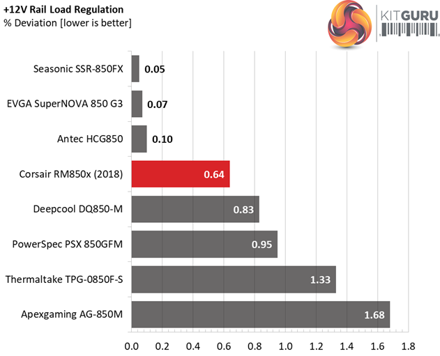
The transient response at +12V is a bit higher than the competing offerings. We would be fully satisfied with a lower than 0.6% deviation on this rail. On the other side, the minor rails perform superb here, including the 3.3V rail which usually is the weak link in these tests.
Here are the oscilloscope screenshots we took during Advanced Transient Response Testing:
Transient Response At 20 Percent Load – 200ms
Transient Response At 20 Percent Load – 20ms
Transient Response At 20 Percent Load – 1ms
Transient Response At 50 Percent Load – 200ms
Transient Response At 50 Percent Load – 20ms
Transient Response At 50 Percent Load – 1ms
Turn-On Transient Tests
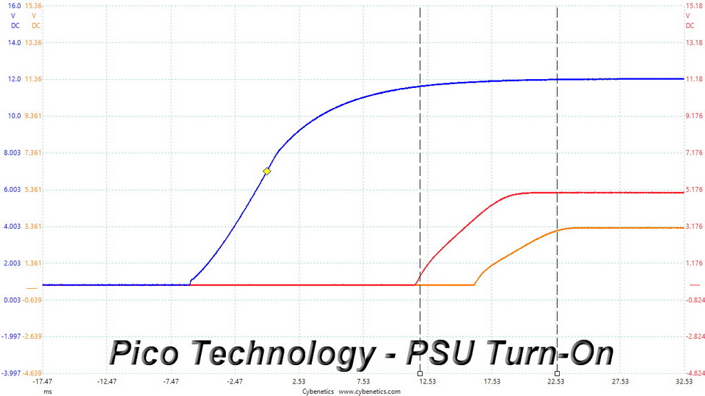
In the next set of tests, we measure the RM850x’s response in simpler transient load scenarios—during its power-on phase.
For our first measurement, we turn the RM850x off, dial in the maximum current the 5VSB rail can handle, and switch the PSU back on.
In the second test, we dial the maximum load the +12V rail can handle and start the PSU while it is in standby mode. In the last test, while the PSU is completely switched off (we cut off the power or switch the PSU off through its power switch), we dial the maximum load the +12V rail can handle before restoring power. The ATX specification states that recorded spikes on all rails should not exceed 10 percent of their nominal values (+10 percent for 12V is 13.2V, and 5.5V for 5V).
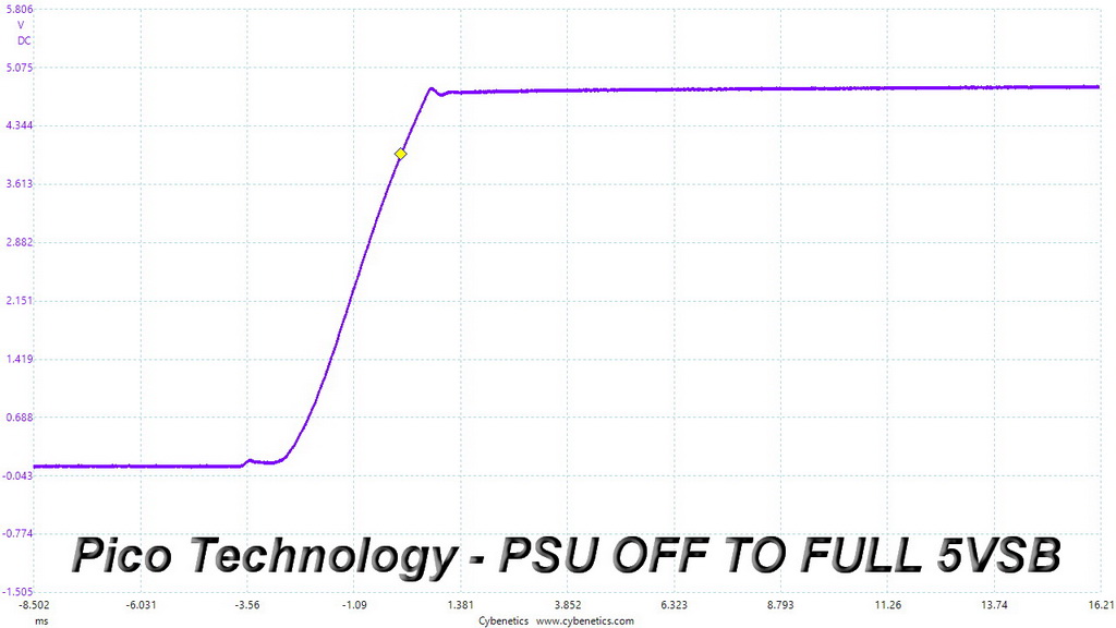
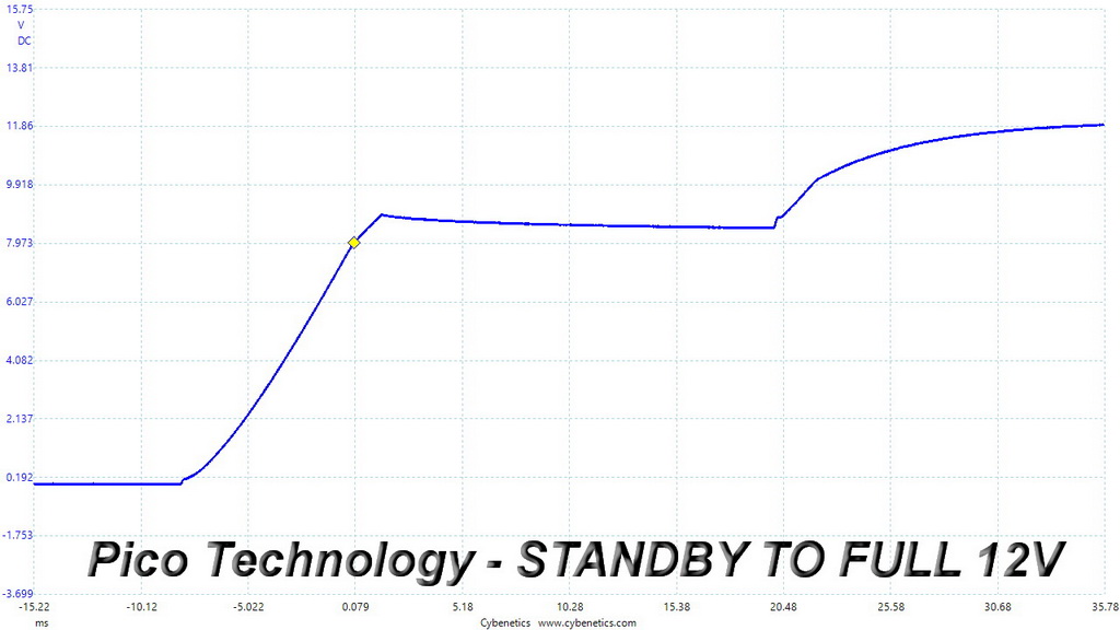
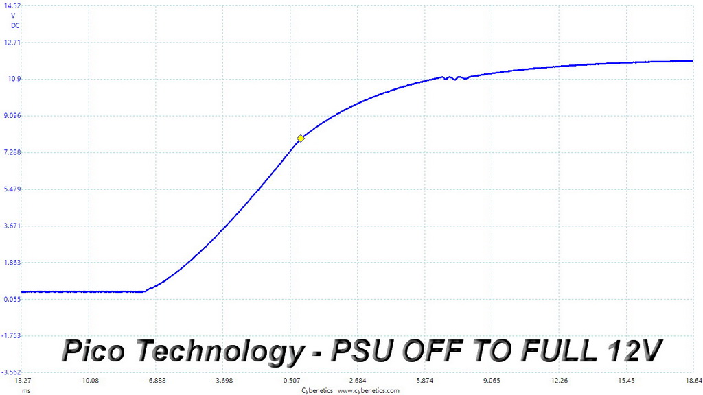
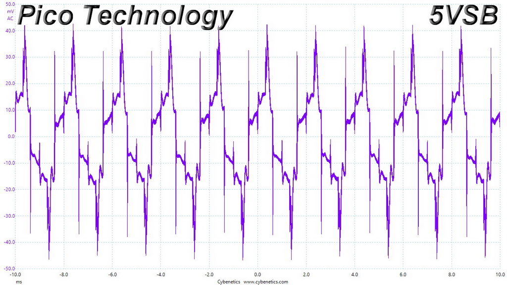
There is a tiny spike at 5VSB, while in the second test the rail takes quite some time to reach its nominal voltage. In any case there are no notable spikes or voltage overshoots.
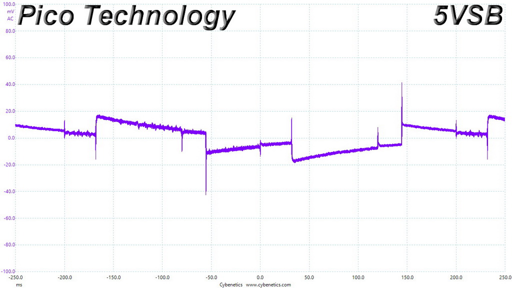
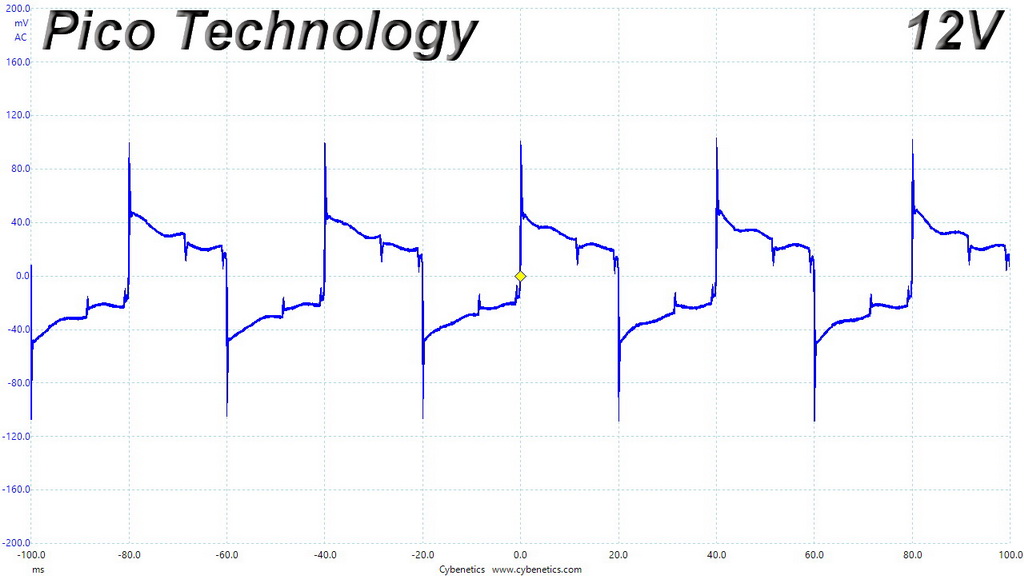
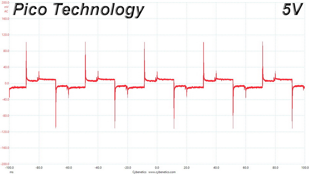
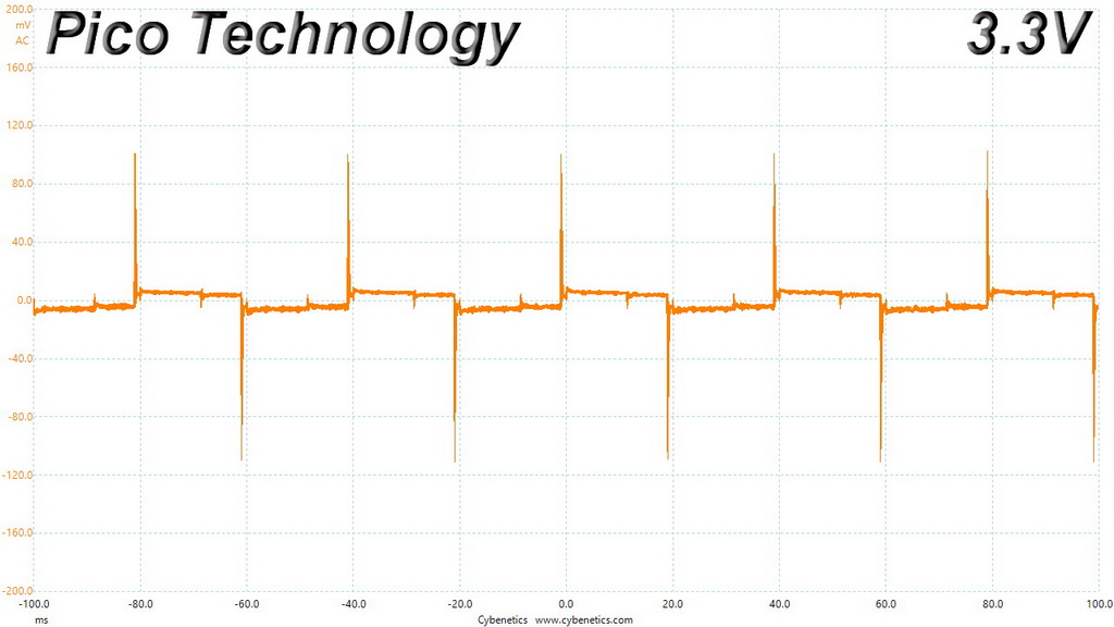
To learn how we measure ripple, please click here.
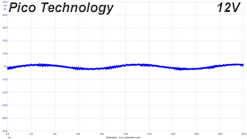
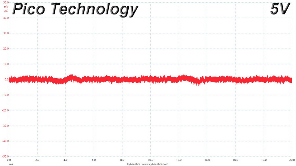
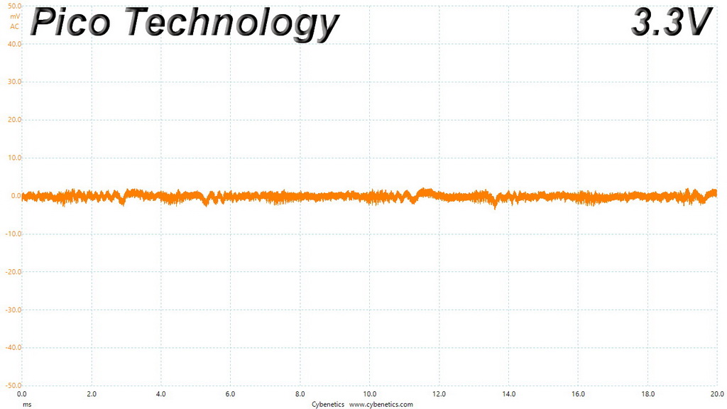
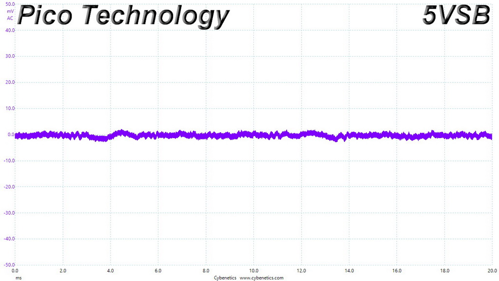
The following table includes the ripple levels we measured on the RM850x’s rails. The limits, according to the ATX specification, are 120mV (+12V) and 50mV (5V, 3.3V, and 5VSB).
| Test | 12V | 5V | 3.3V | 5VSB | Pass/Fail |
| 10% Load | 1.6 mV | 3.8 mV | 2.8 mV | 1.9 mV | Pass |
| 20% Load | 8.0 mV | 5.0 mV | 4.8 mV | 3.5 mV | Pass |
| 30% Load | 6.6 mV | 4.3 mV | 3.2 mV | 2.4 mV | Pass |
| 40% Load | 5.9 mV | 5.7 mV | 5.3 mV | 3.7 mV | Pass |
| 50% Load | 5.7 mV | 5.8 mV | 5.0 mV | 3.6 mV | Pass |
| 60% Load | 6.2 mV | 5.5 mV | 4.4 mV | 3.4 mV | Pass |
| 70% Load | 6.2 mV | 8.1 mV | 5.7 mV | 5.6 mV | Pass |
| 80% Load | 6.3 mV | 6.4 mV | 5.9 mV | 4.1 mV | Pass |
| 90% Load | 7.0 mV | 7.2 mV | 6.9 mV | 5.1 mV | Pass |
| 100% Load | 7.2 mV | 8.5 mV | 7.2 mV | 5.7 mV | Pass |
| 110% Load | 7.3 mV | 8.4 mV | 6.4 mV | 5.7 mV | Pass |
| Crossload 1 | 7.0 mV | 7.3 mV | 6.5 mV | 3.3 mV | Pass |
| Crossload 2 | 6.9 mV | 6.1 mV | 4.0 mV | 4.2 mV | Pass |
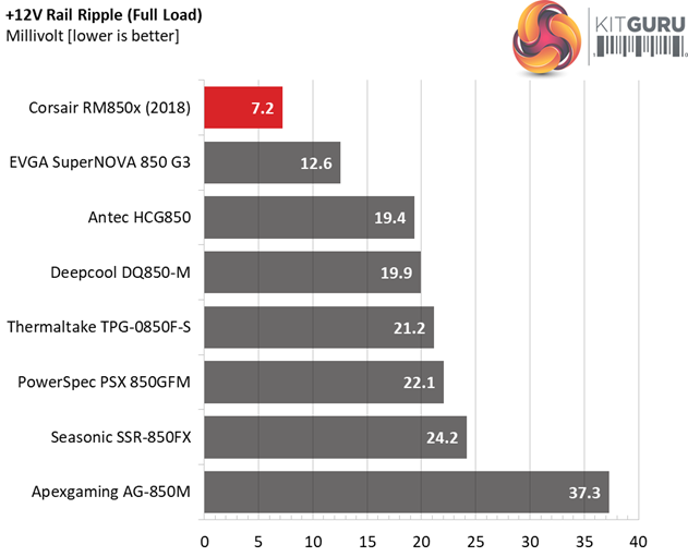
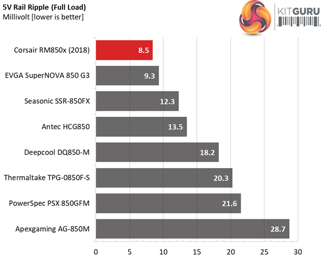
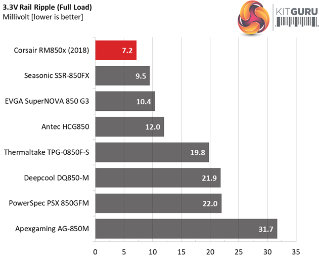
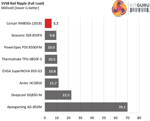
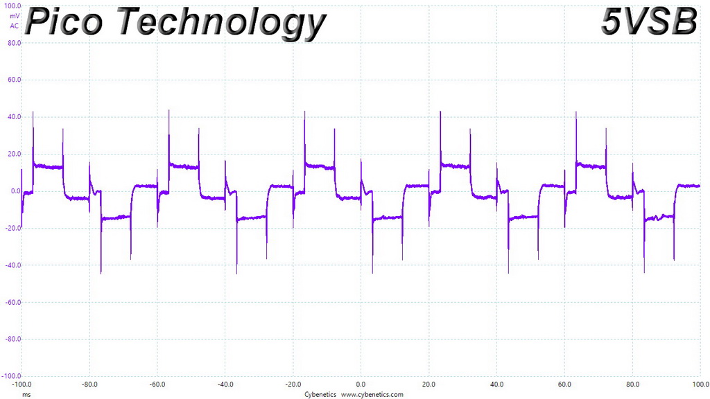
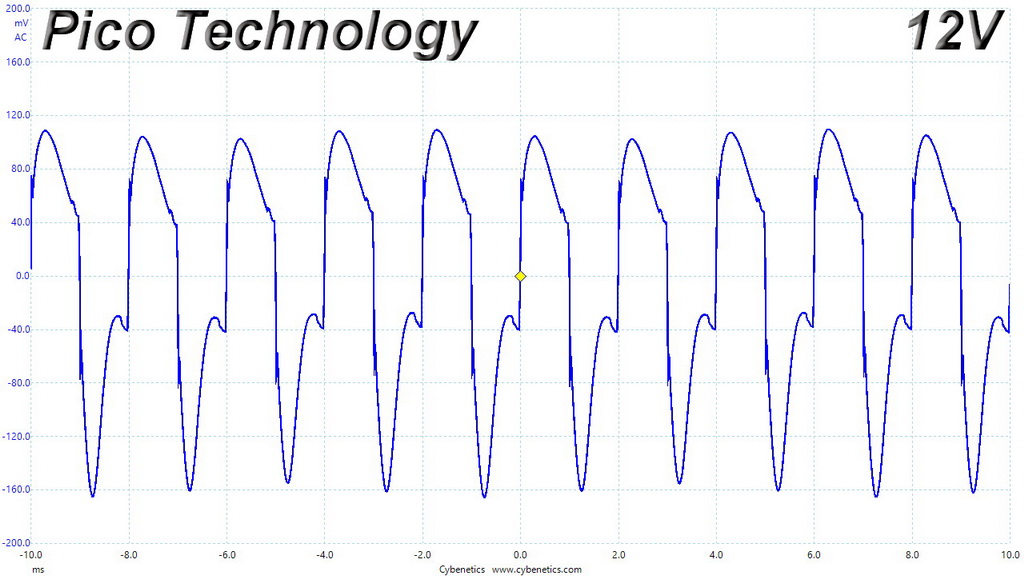
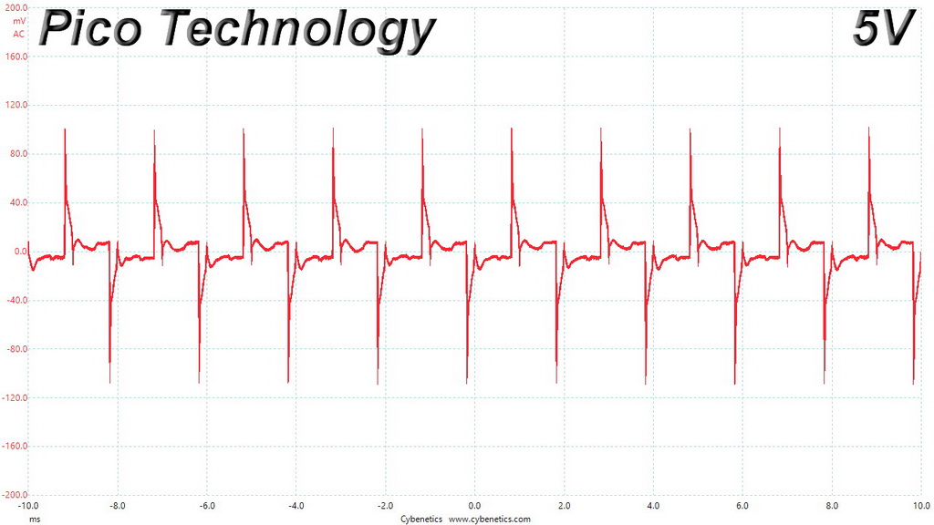
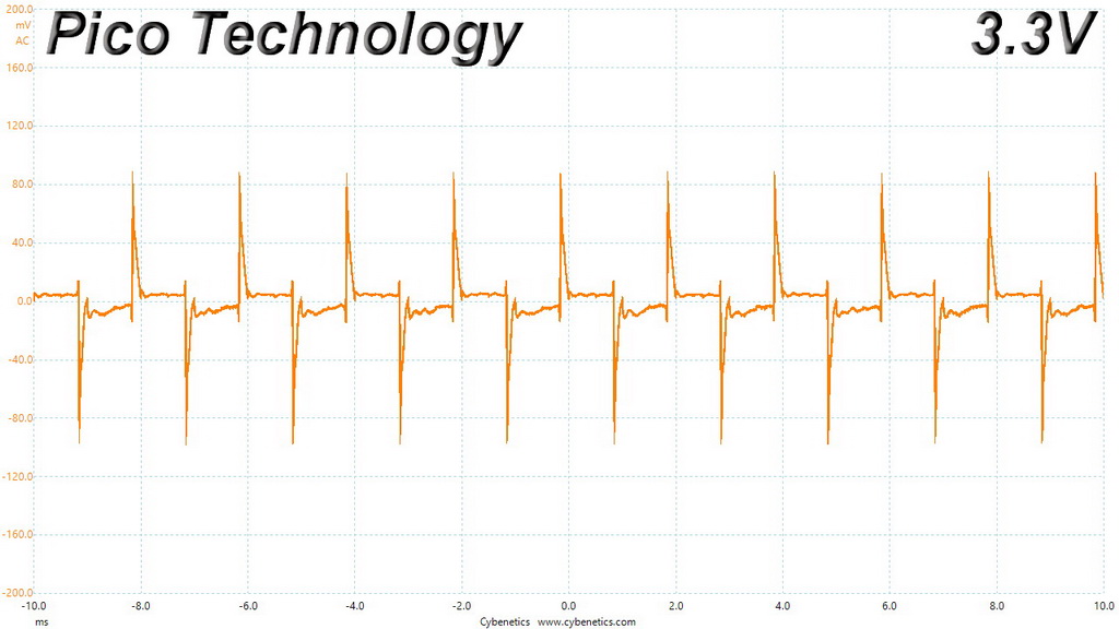
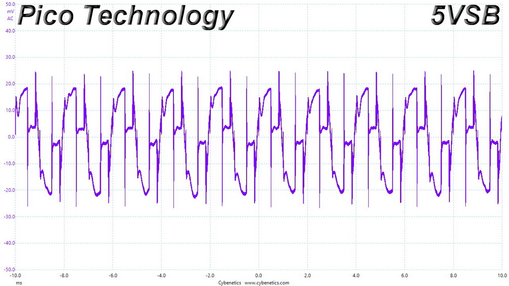
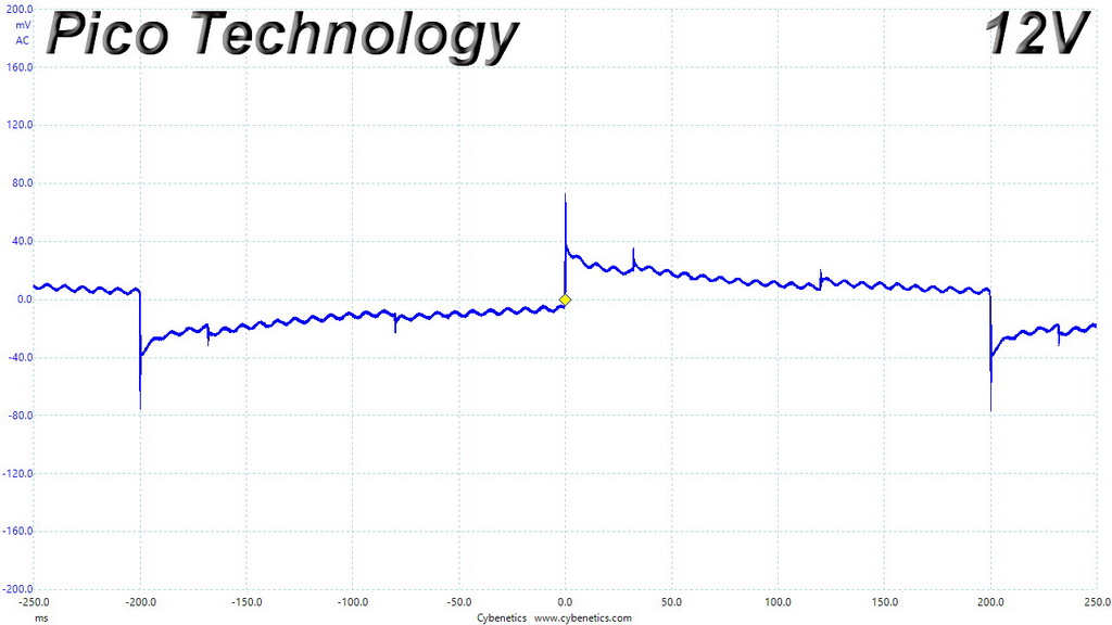
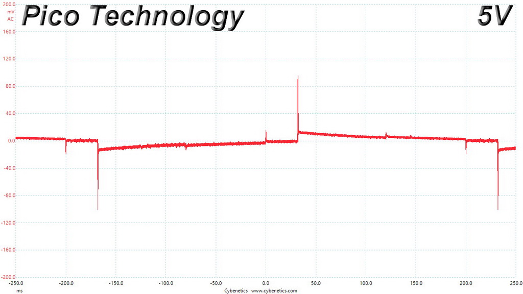
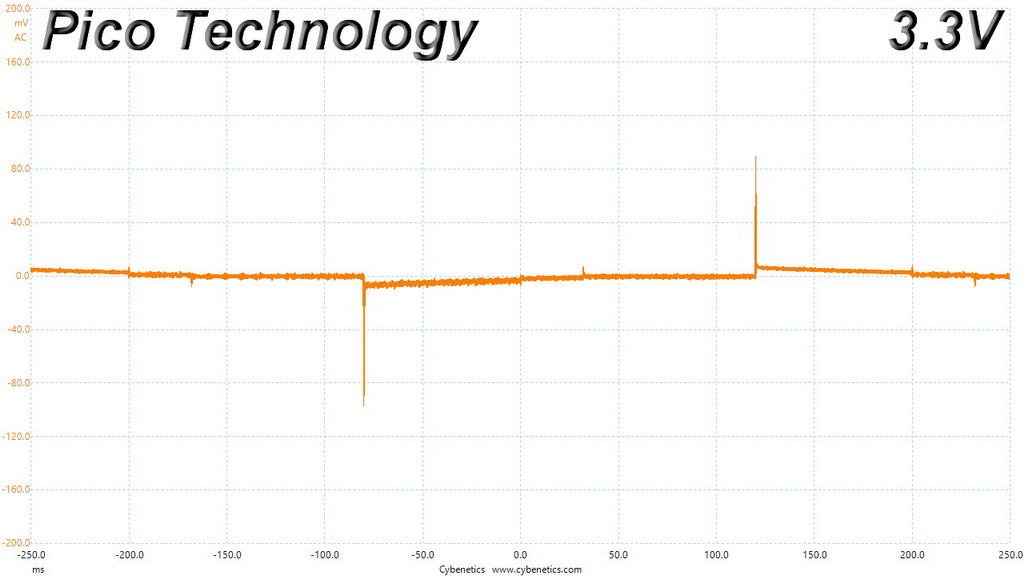
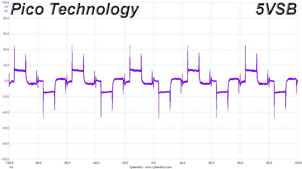
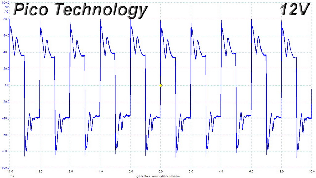
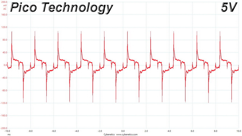
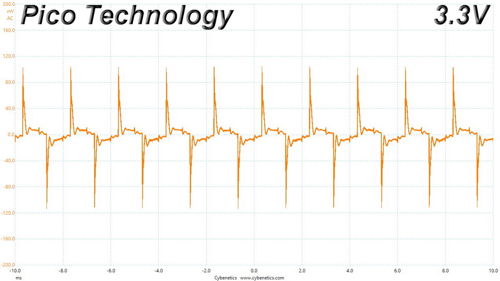
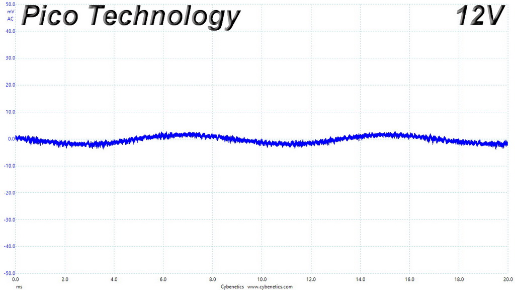
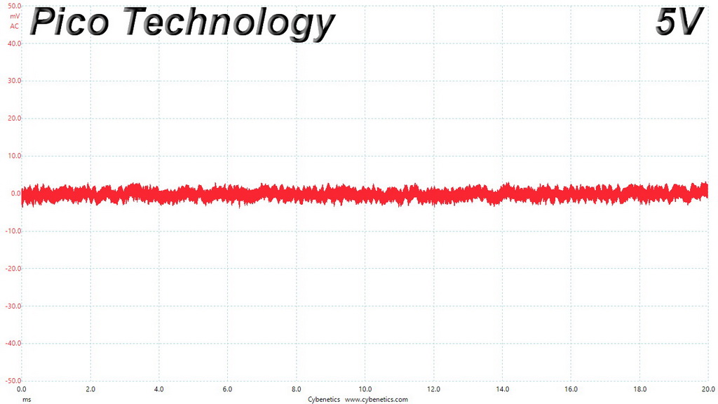
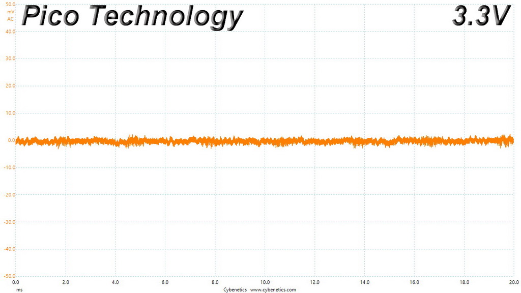
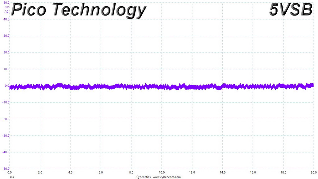
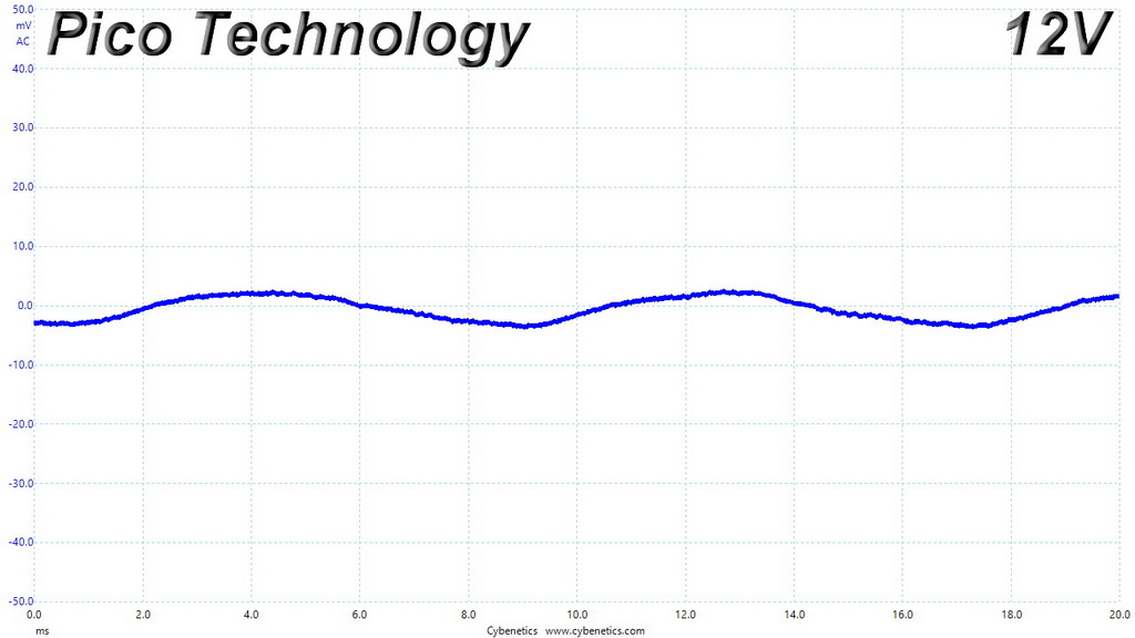
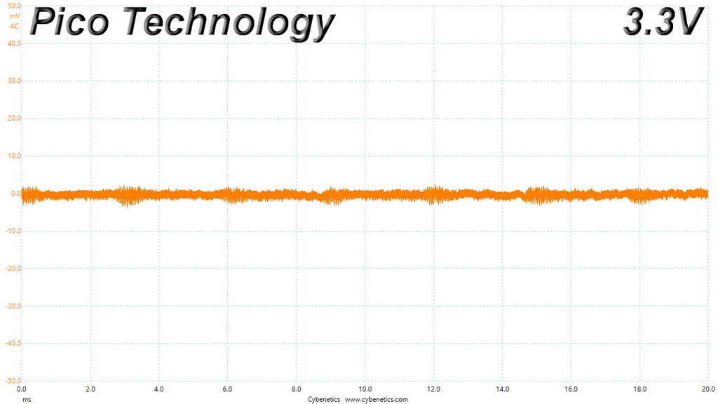
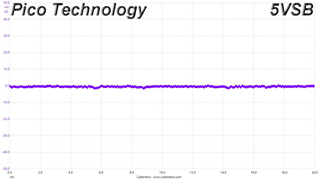
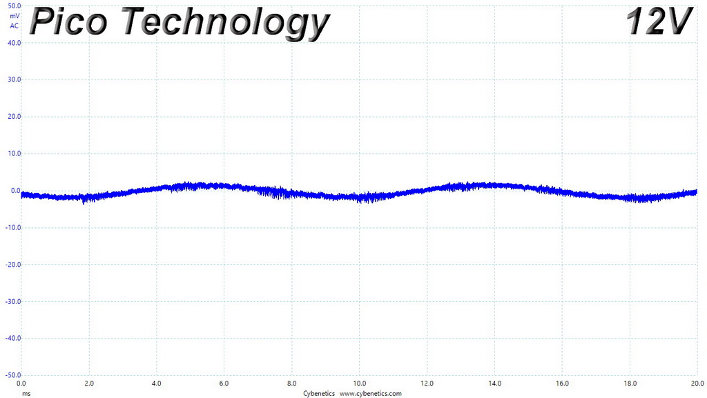
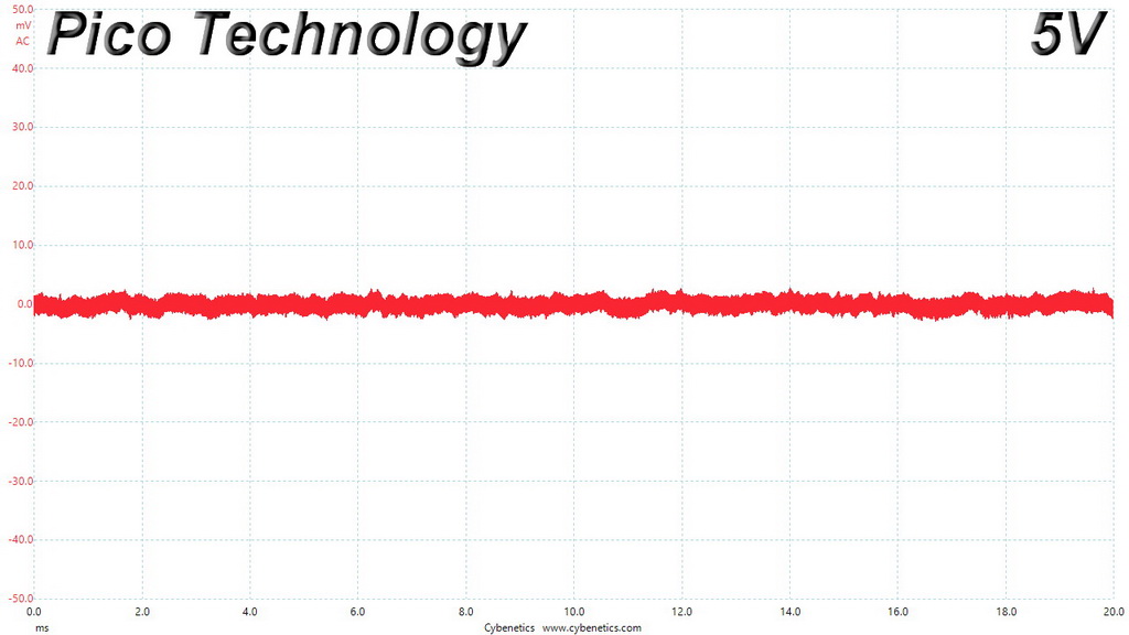
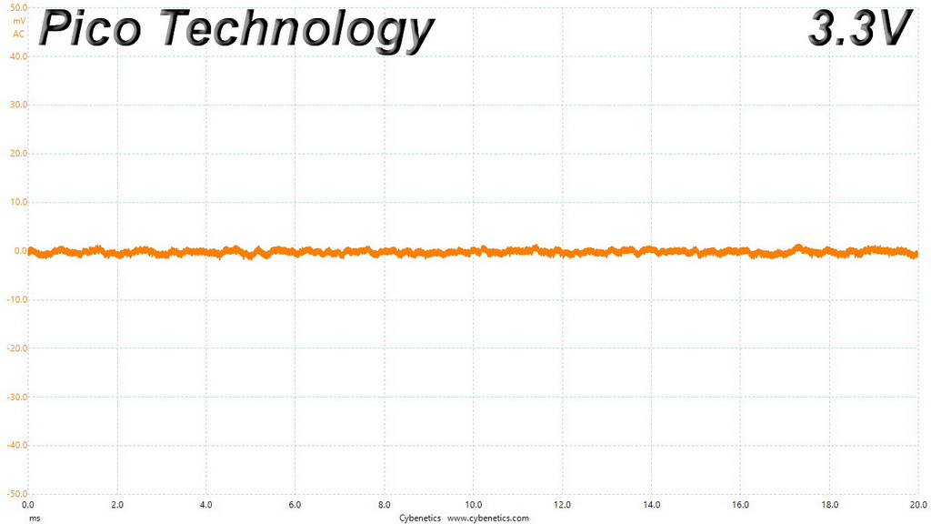
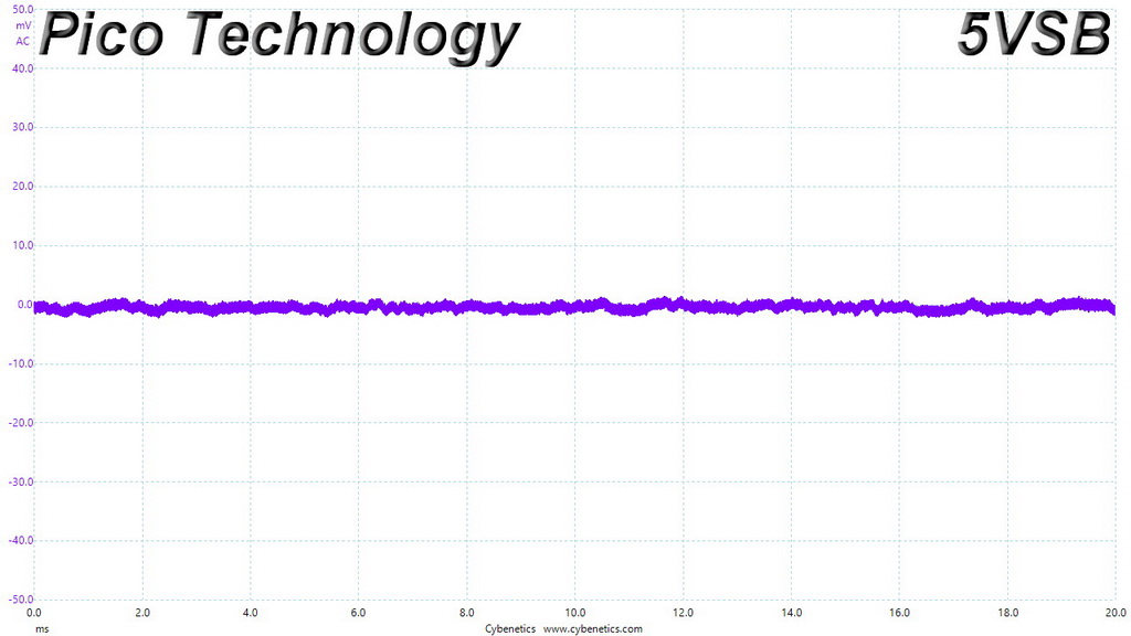
The ripple suppression is amazing! The combination of a good design and the in-cable caps makes wonders.
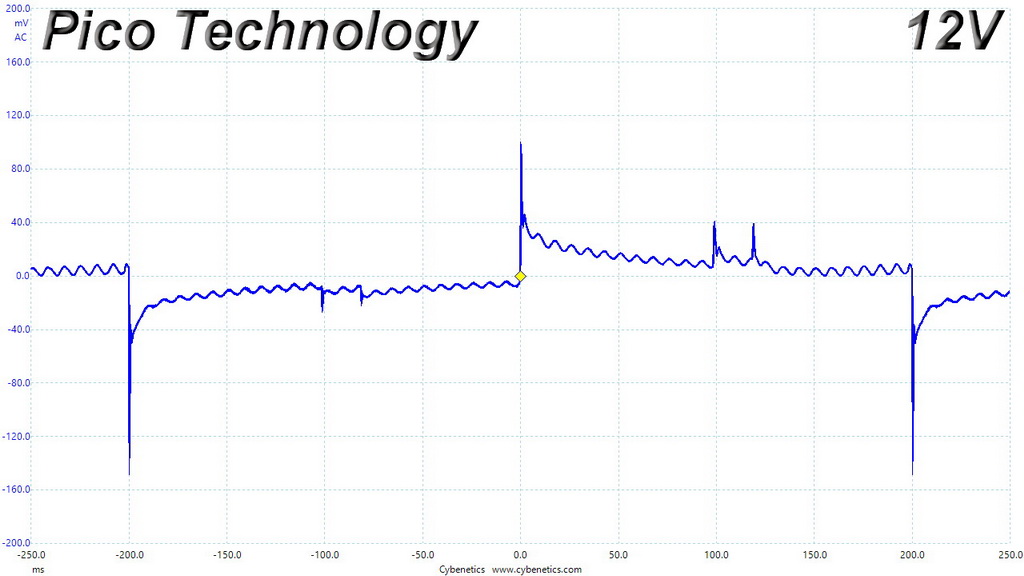
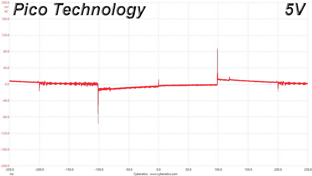
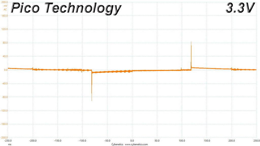
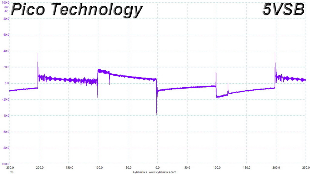
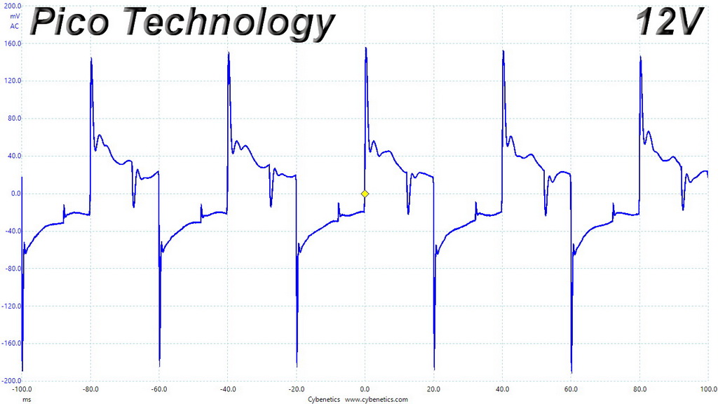
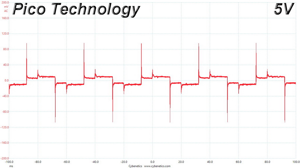
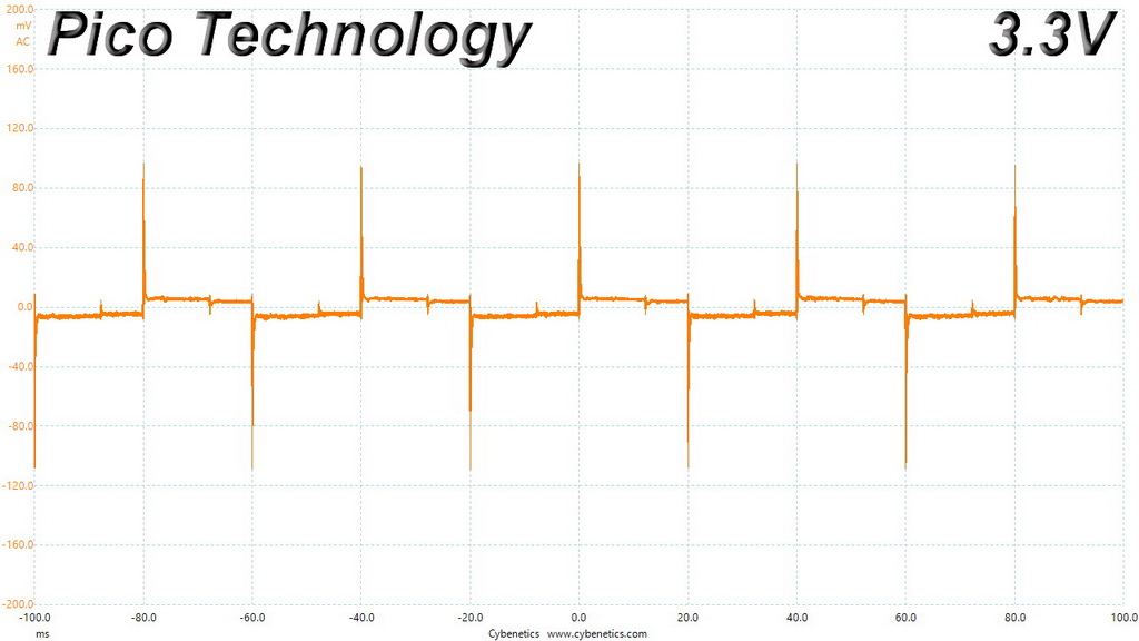
Ripple Oscilloscope Screenshots
The following oscilloscope screenshots illustrate the AC ripple and noise registered on the main rails (+12V, 5V, 3.3V and 5VSB). The bigger the fluctuations on the screen, the bigger the ripple/noise. We set 0.01 V/Div (each vertical division/box equals 0.01V) as the standard for all measurements.
Ripple At Full Load
Ripple At 110-Percent Load
Ripple At Cross-Load 1

Ripple At Cross-Load 2
To learn more about our EMI testing equipment, please check out How We Test Power Supply Units.
EMI Results – Average Detector
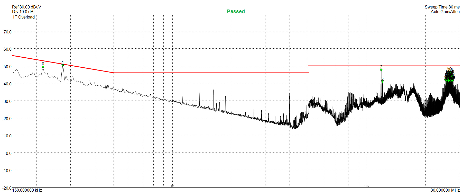
EMI Results – Peak Detector
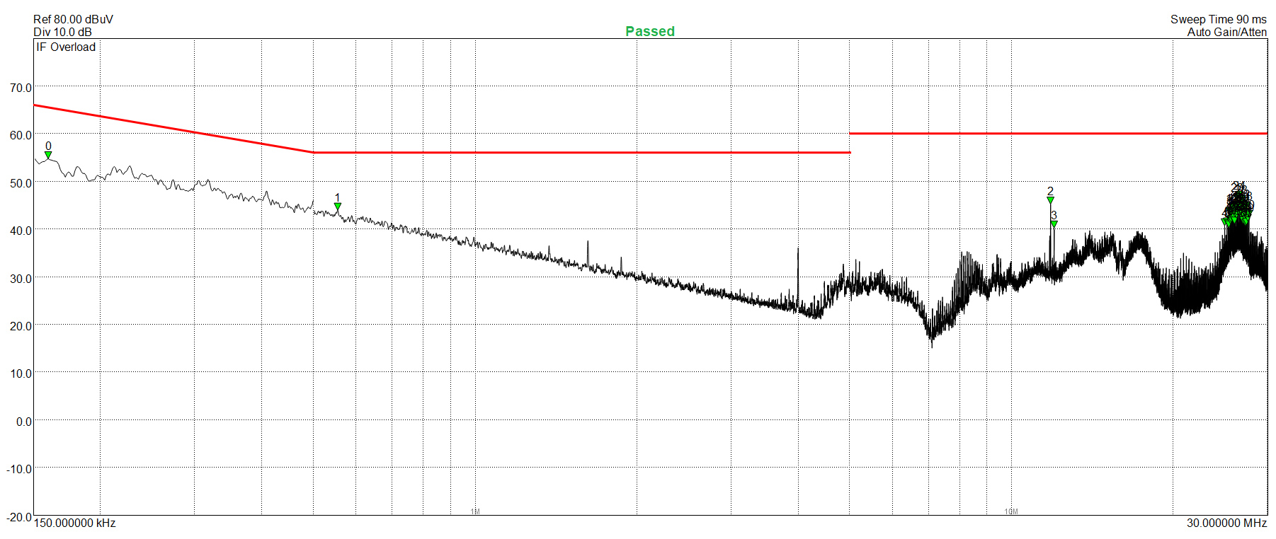
With both AVG and Peak detectors the EMI filter performs well, since it doesn't allow the conducted EMI emissions to exceed the limits.
Performance Rating
The following graph shows the RM850x’s total performance rating, comparing it to other units we have tested. To be more specific, the tested unit is shown as 100 percent, and every other unit's performance is shown relative to it.
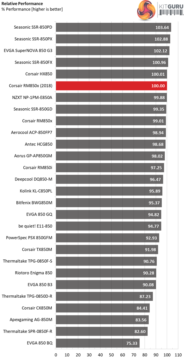
The overall performance of the new RM850x is a bit higher compared to the previous generation. In general the RM850x is highly competitive, easily meeting the competition eye to eye.
Performance Per Dollar
The following chart may be the most interesting to many of you because it depicts the product’s performance-per-dollar score. We looked up the current price of each PSU on popular online shops and used those prices and all relative performance numbers to calculate the index. Note that all of the numbers in the following graphs are normalized by the rated power of each unit.
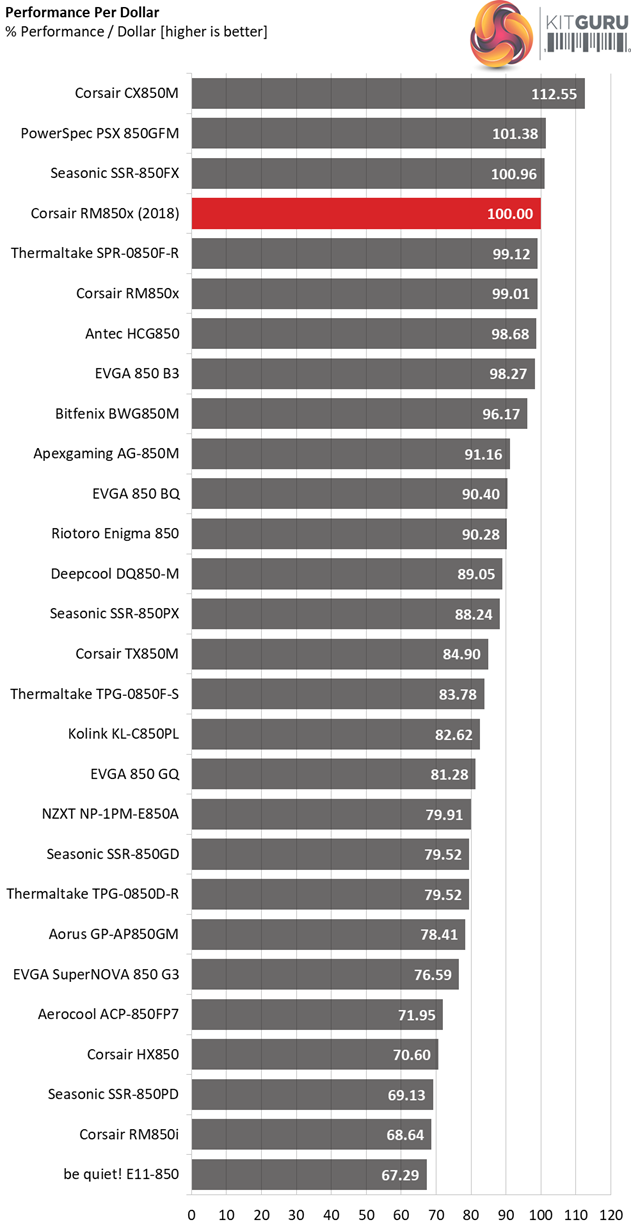
The pricing scheme is good in the US market, however in the UK the RM850x is much more expensive.
Noise Rating
The graph below depicts the cooling fan's average noise over the PSU's operating range, with an ambient temperature between 30°C and 32°C (86°F to 89.6°F).
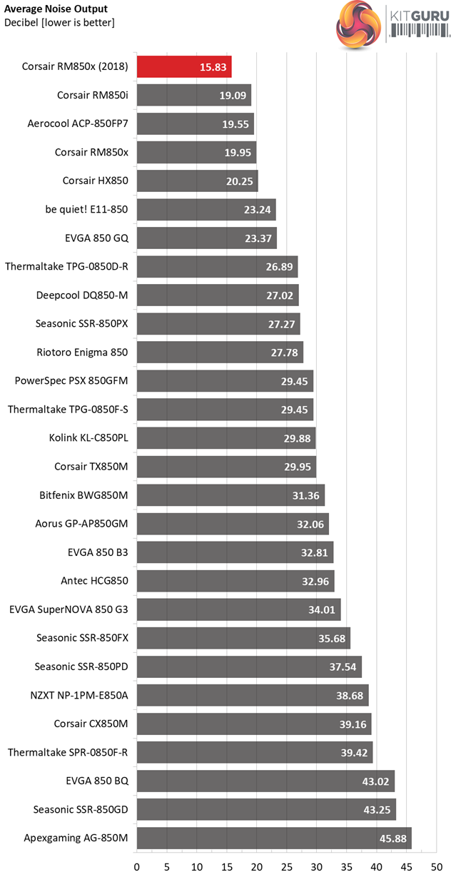
In the noise output section the new RM850x takes over the first place leaving competitors like the Seasonic Focus Plus Gold and the EVGA 850 G3 far behind.
Efficiency Rating
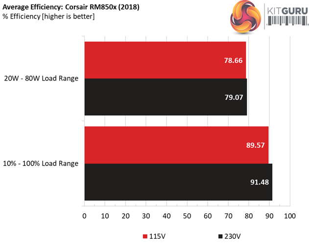
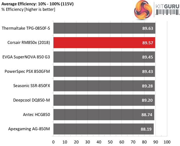
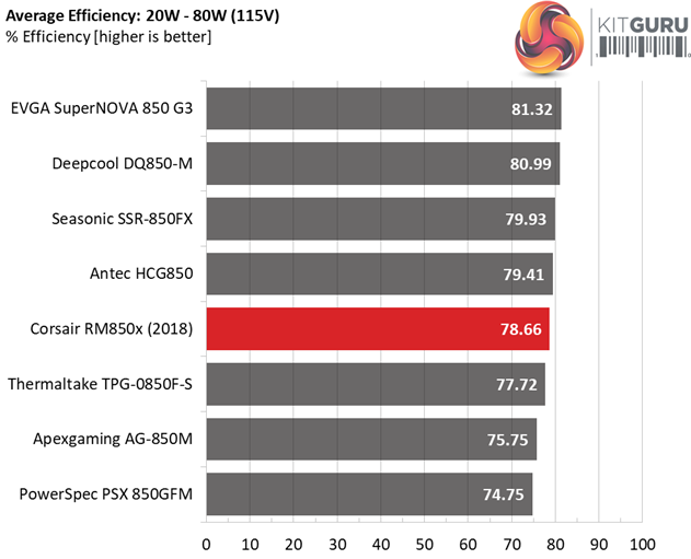
The following graph shows the PSU's average efficiency throughout its operating range, with an ambient temperature close to 30°C.
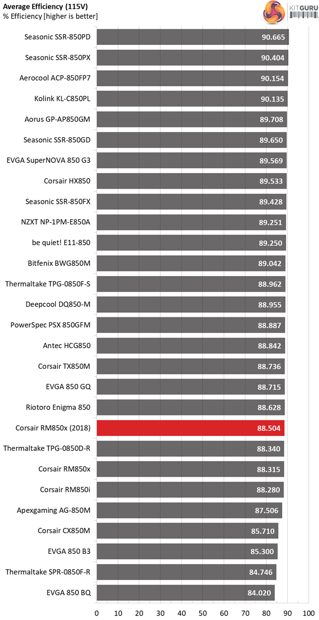
The new model is slightly more efficient than the old one. The SSR-850FX and the 850 G3, which are direct competitors of this product, perform better here however.
The Corsair RM850x retails for $119.99 in the US while in the UK market you will find it from £110 to £149.99 (including VAT), depending on the store.
Corsair along with CWT had a difficult task, to make something good even better without increasing the production cost. The RMx units are among the most popular models in today's PSU market so every change had to be carefully planned in order not to let down the potential buyers. The final result is fully satisfactory since the new RM850x achieves a higher overall performance score than its predecessor and on top of that it has smaller dimensions, it is quieter and it features a bypass relay for its NTC thermistor, meaning that the inrush current protection has been greatly enhanced.
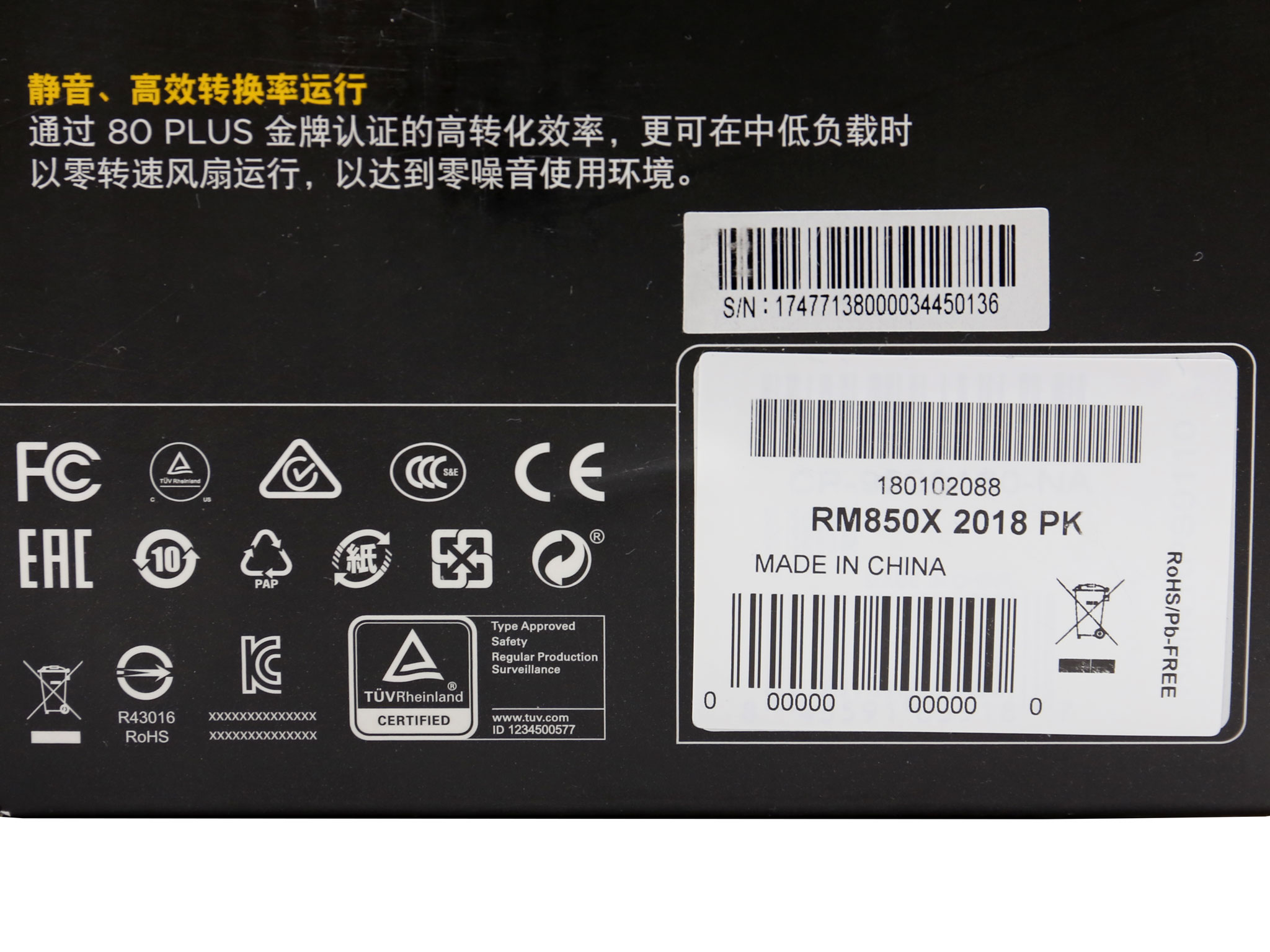
For those of you wondering how someone can identify the new RM850x from the old one, all you have to do is to take a look at the small white sticker at the package's rear side and see if it says “2018” right next to the model number.
Another way is to check the dimensions of the PSU, which are also depicted on the rear of the box. If 160mm is mentioned as length then it is the new unit, since the old one measured 180mm. Most likely though soon enough there will be no stock available of the older RM850x and it won't be a problem. Until then, however, take care to ensure you get the newest model.
There is no doubt that the RM850x is a one way road for users wanting to build a super silent system. The Seasonic SSR-850FX and EVGA 850 G3 might be a bit more efficient, however The RM850x is an extremely quiet power supply that has no competition in this regard.
![]()
You can get the Corsair RM850x from Overclockers UK for £149.99 inc VAT HERE.
Pros:
- Delivered full power at 47°C.
- High performance.
- Super silent operation.
- Good build quality.
- Fully modular.
- 2x EPS and 6x PCIe connectors.
- Compact dimensions.
- 10 year warranty.
Cons:
- High inrush current with 230V.
- In-cable caps which make the modular cables bulky.
- Short distance between peripheral connectors.
- No fan-test button.
KitGuru says: The new RM850x offers slightly higher performance compared to the previous generation model, while at the same time it is even quieter, has smaller dimensions and maintains the same price tag. If you want a high performance PSU for a whisper quiet system then this unit should be top of your shortlist.