

The DQ850-M promises high performance along with 80 PLUS Gold and ETA-A efficiency levels. It uses a 120mm FDB fan, which offers quiet overall operation while the provided warranty is 5 years (it has been extended to ten-years now). Since this power supply uses quality parts including Japanese caps, it will easily outlast the provided warranty, given that you power it through a stable mains grid.
Deepcool is a Chinese company mostly known for its impressive looking chassis. The same company also sell air cooled and liquid CPU coolers as well as power supplies. Although it has been quite a while since the last time that we got our hands on a Deepcool PSU, a look at the official site reveals a large number of corresponding products with the majority of them addressing mainstream systems.
Recently Deepcool released three new units which belong to its GameStorm line: the DQ850-M, DQ750-M and DQ650-M. The “M” letter stands for modular, since all three models are fully modular.
The manufacturer is Channel Well Technology and this particular platform ranges from 650W to 850W. Today we will take a detailed look at the flagship GameStorm unit, the DQ850-M.
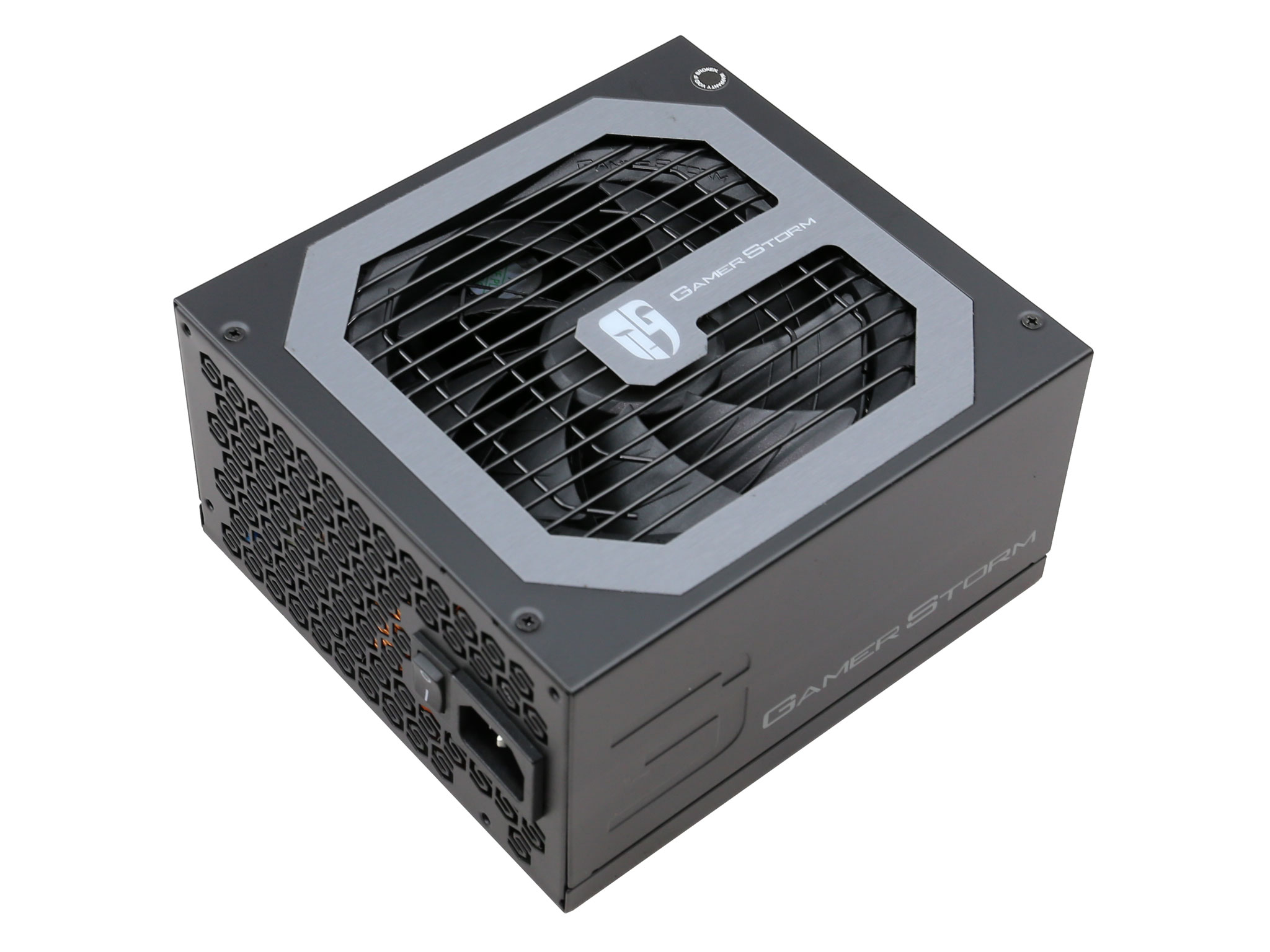
Given its capacity, the DQ850-M has compact enough dimensions with 162mm depth. There are however even smaller PSUs in the same capacity category – for example the Seasonic SSR-850FX which only measures 140mm in length.
Deepcool's offering has more appealing looks though, with the nicely designed fan grille stealing the show. We should note that the GameStorm unit with 750W capacity is the only one from the line featuring a white chassis.
Read our How We Test Power Supplies HERE
Specifications
| Manufacturer (OEM) | Channel Well Technology |
| Max. DC Output | 850W |
| Efficiency | 80 PLUS Gold, ETA-A (88-91%) |
| Noise | LAMBDA-A- (25-30 dB[A]) |
| Modular | ✓ (Fully) |
| Intel C6/C7 Power State Support | ✓ |
| Operating Temperature (Full Load) | 0 – 50°C |
| Over Voltage Protection | ✓ |
| Under Voltage Protection | ✓ |
| Over Power Protection | ✓ |
| Over Current (+12V) Protection | ✓ |
| Over Temperature Protection | ✓ |
| Short Circuit Protection | ✓ |
| Surge Protection | ✓ |
| Inrush Current Protection | ✓ |
| Fan Failure Protection | ✗ |
| No Load Operation | ✓ |
| Cooling | 120mm Fluid Dynamic Bearing Fan (DF1202512CH-003) |
| Semi-Passive Operation | ✗ |
| Dimensions (W x H x D) | 152 x 88 x 162mm |
| Weight | 1.60kg (3.53lb) |
| Form Factor | ATX12V v2.4, EPS 2.92 |
| Warranty | 5 Years (has been extended to ten-years) |
This unit is based on a CWT platform and more specific the GPU850V-G. In the Cybenetics scale it scores ETA-A and LAMBDA-A- efficiency and noise certifications and it is also 80 PLUS Gold certified.
The max operating temperature for full load delivery is 50°C and all necessary protection features are supported. Strangely enough, although the chassis is large enough to accommodate a 140mm fan, Deepcool decided to use a smaller, 120mm diameter fan. We are strong supporters of using the larger supported fan since it can offer the same airflow but with lower noise output levels.
Lastly, the provided warranty is long enough at five years. Compared to other brands such as Corsair, EVGA and Seasonic which offer ten to twelve years, Deepcool's offering might look short. [25/9/18 Update: Deepcool informed us that the provided warranty has been extended to ten-years]
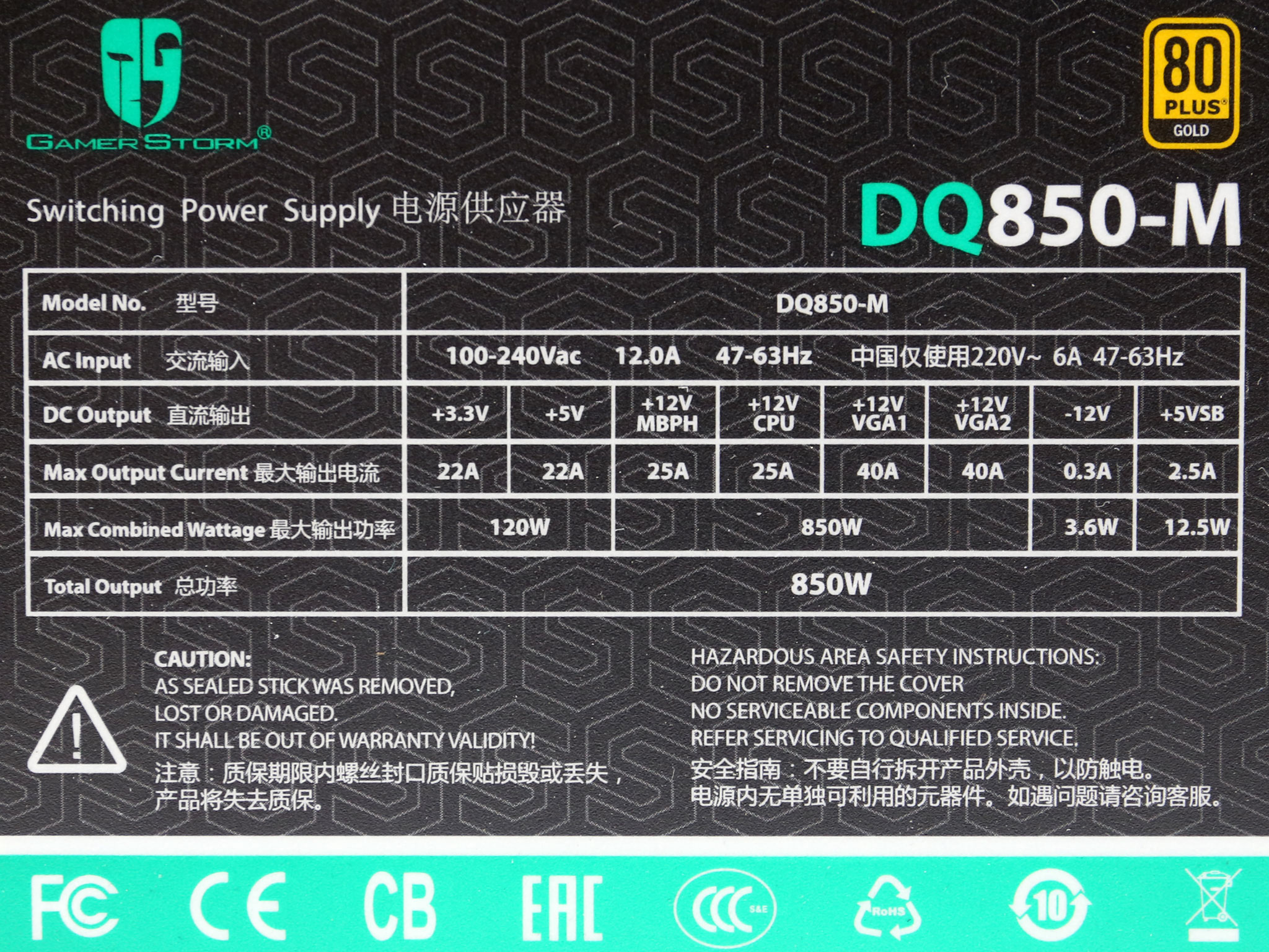
Power Specifications
| Rail | 3.3V | 5V | 12V MBPH | 12V CPU | 12V VGA1 | 12V VGA2 | 5VSB | -12V | |
| Max. Power | Amps | 22 | 22 | 25 | 25 | 40 | 40 | 2.5 | 0.3 |
| Watts | 120 | 850 | 12.5 | 3.6 | |||||
| Total Max. Power (W) | 850 | ||||||||
There are four +12V rails which combined can deliver the unit's full power. The minor rails are quite strong with 120W max combined power, while the 5VSB rail officially can deliver up to 2.5A current output.
Cables & Connectors
| Modular Cables | ||||
| Description | Cable Count | Connector Count (Total) | Gauge | In Cable Capacitors |
|---|---|---|---|---|
| ATX connector 20+4 pin (550mm) | 1 | 1 | 18AWG | No |
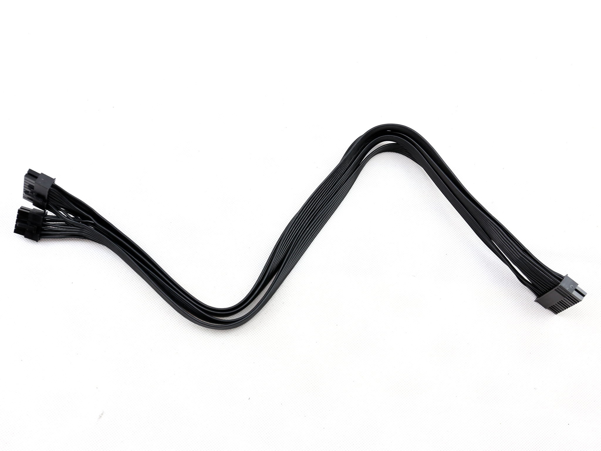
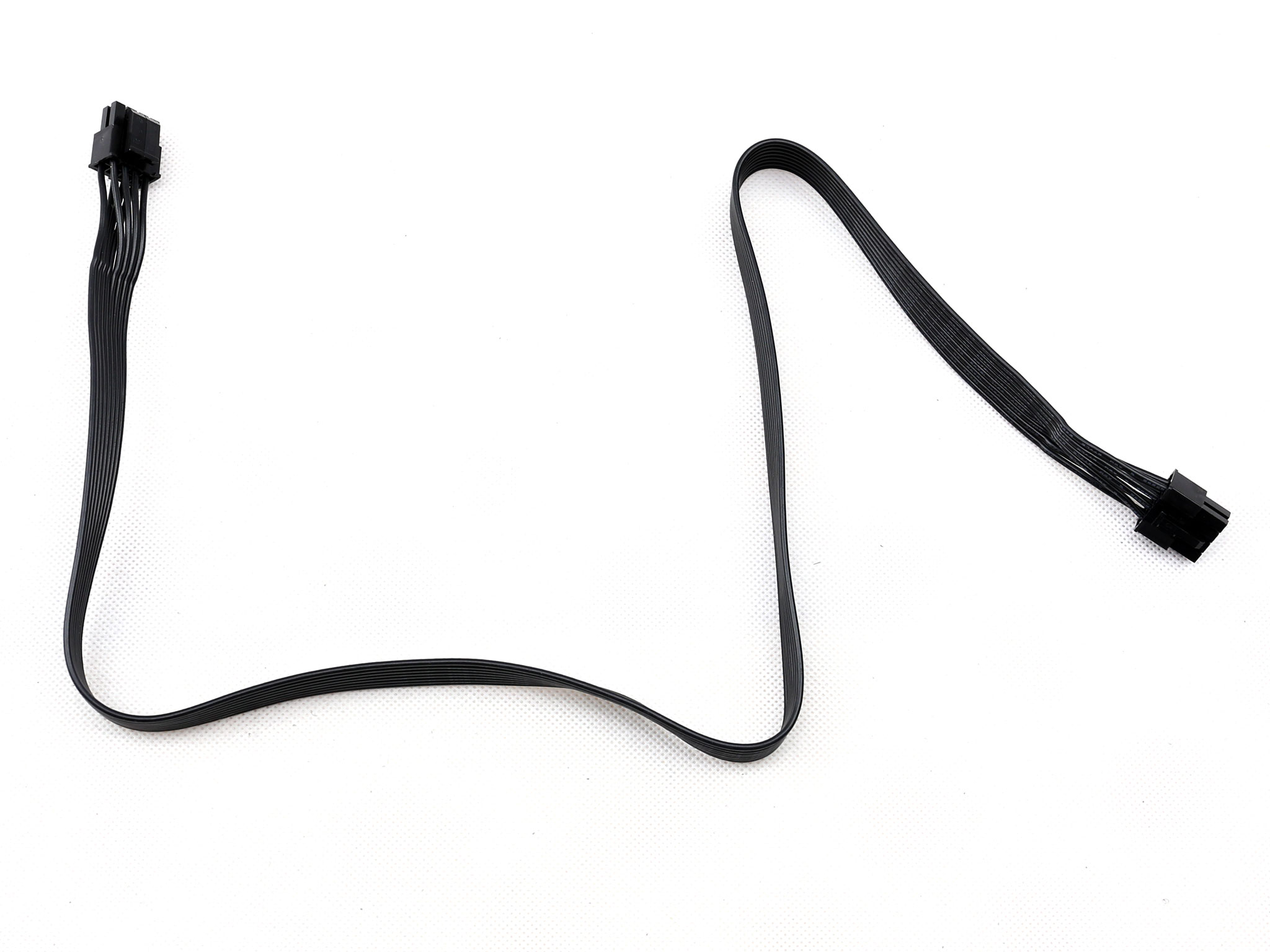
| 4+4 pin EPS12V (700mm) | 2 | 2 | 18AWG | No |
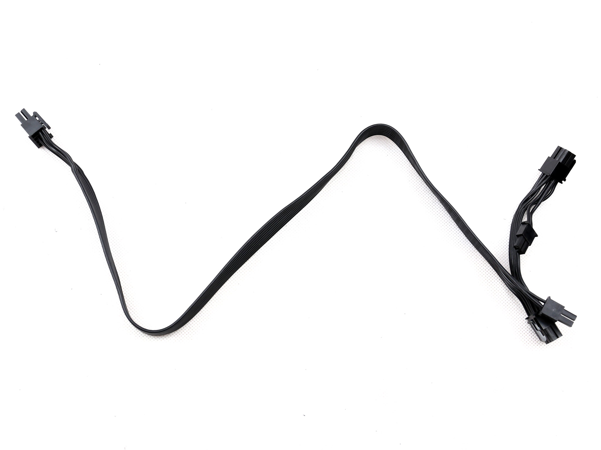
| 6+2 pin PCIe (500mm+100mm) | 2 | 4 | 18AWG | No |
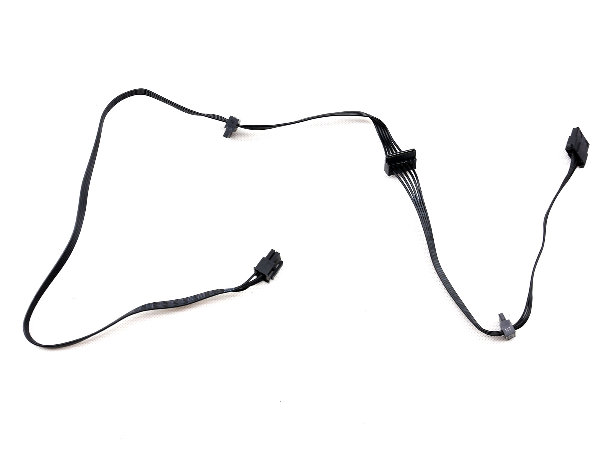
| SATA (550mm+150mm+150mm) / 4-pin Molex (+150mm) | 1 | 3 / 1 | 20AWG | No |
| SATA (450mm+150mm+150mm) / 4-pin Molex (+150mm) | 1 | 3 / 1 | 20AWG | No |
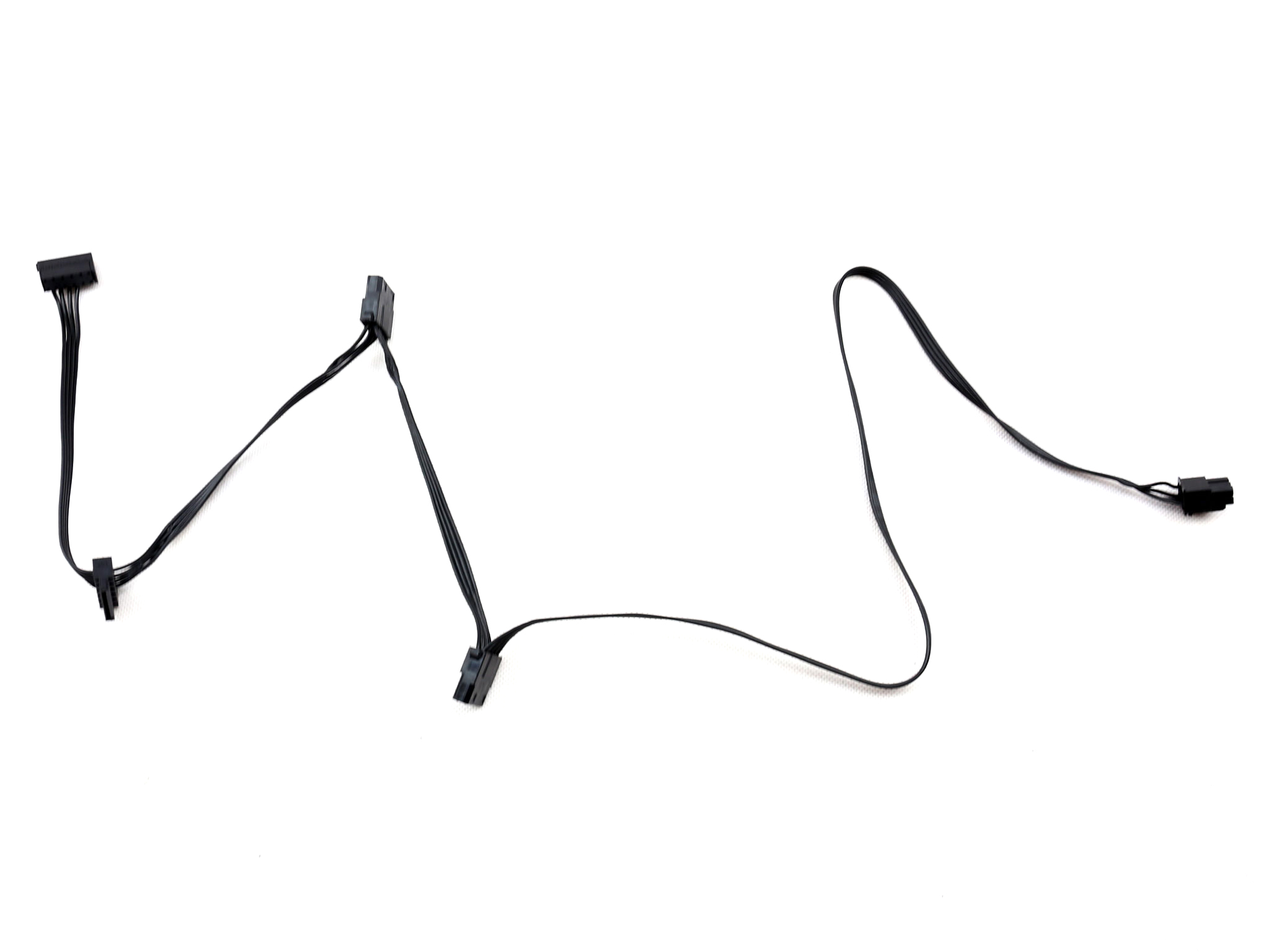
| 4-pin Molex (550mm+150mm) / SATA (+150mm+150mm) | 1 | 2 / 2 | 20AWG | No |
| 4-pin Molex (450mm+150mm) / SATA (+150mm+150mm) | 1 | 2 / 2 | 20AWG | No |
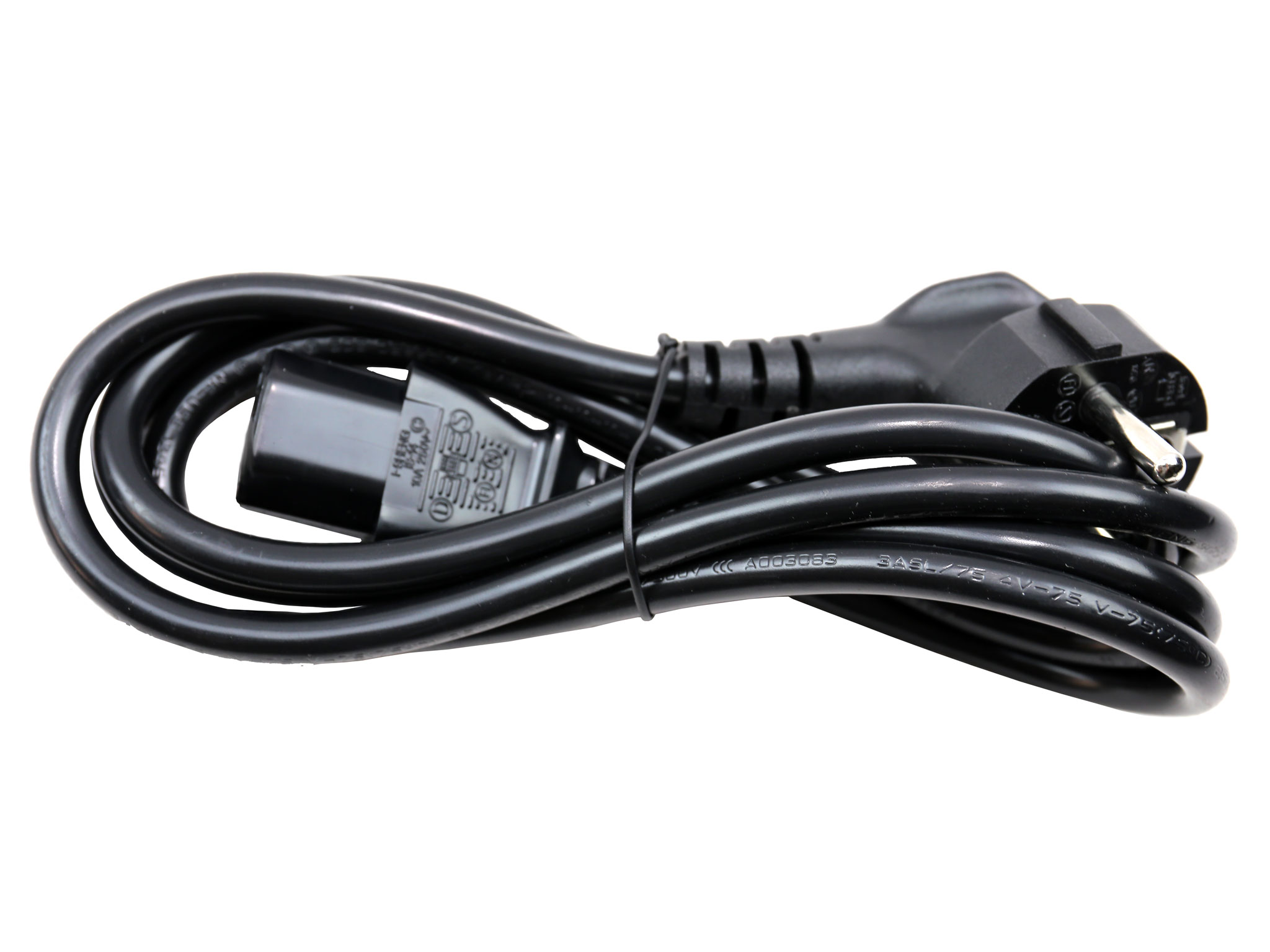
| AC Power Cord (1400mm) – C13 coupler | 1 | 1 | 18AWG | – |
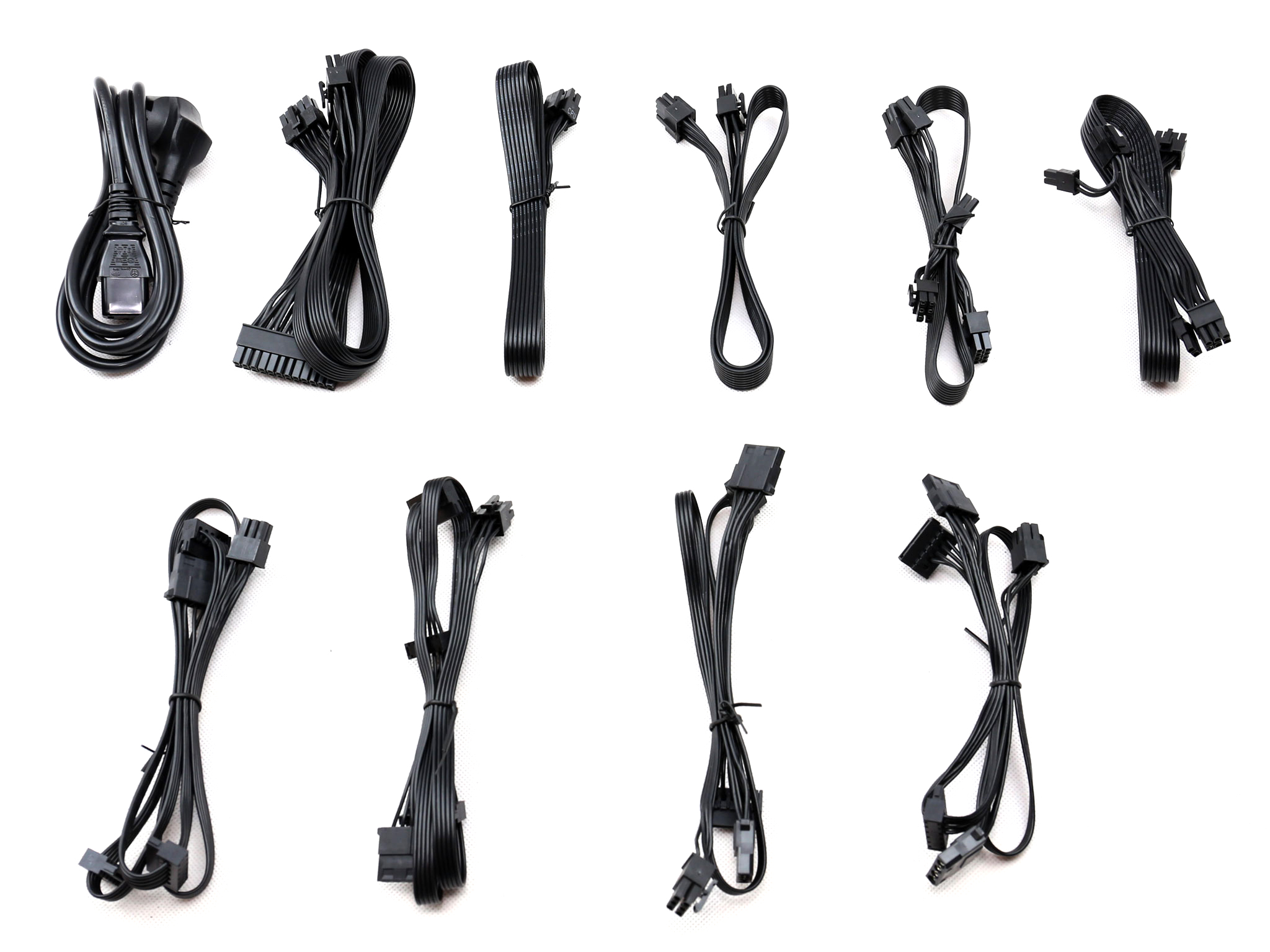
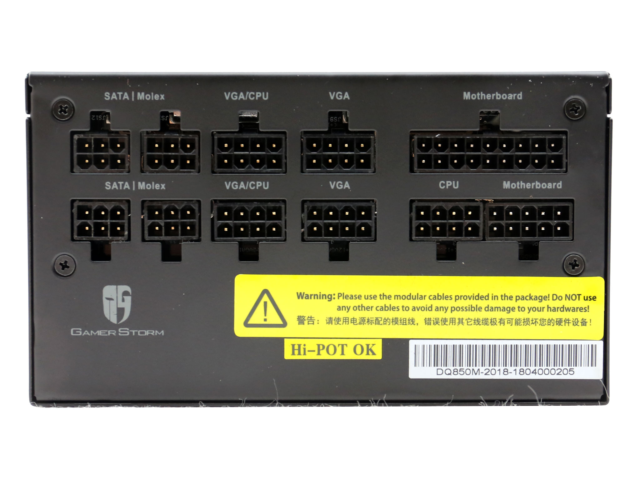
As expected there are two EPS connectors however the number of PCIe looks low at four. Usually the higher-end 850W units come with six PCIe connectors. The number of peripheral connectors is increased and it is good to see them distributed via four cables.
The EPS cables are long, and the distance among the peripheral connectors is adequate at 15cm. Ideally we feel the ATX cable should reach 60cm in length.
Finally, the peripheral cables use 20AWG gauges instead of the 18AWG that the ATX spec mentions. If those cables didn't include the 4-pin Molex connectors, which can handle more Amps than the SATA connectors, then we wouldn't mind so much about the thinner gauge.
Power Distribution
| Power Distribution | |
| 12V1 | ATX |
| 12V2 | CPU |
| 12V3 | VGA1 |
| 12V4 | VGA2 |
The single CPU socket, located close to the couple of motherboard sockets, is powered through the second 12V rail. Since there are two EPS cables, you will have to use one of the VGA/CPU sockets if you need a second EPS connector, meaning that you will end up mixing the PCIe and EPS cables. Ideally those connectors should be powered through separate +12V virtual rails.
Packaging
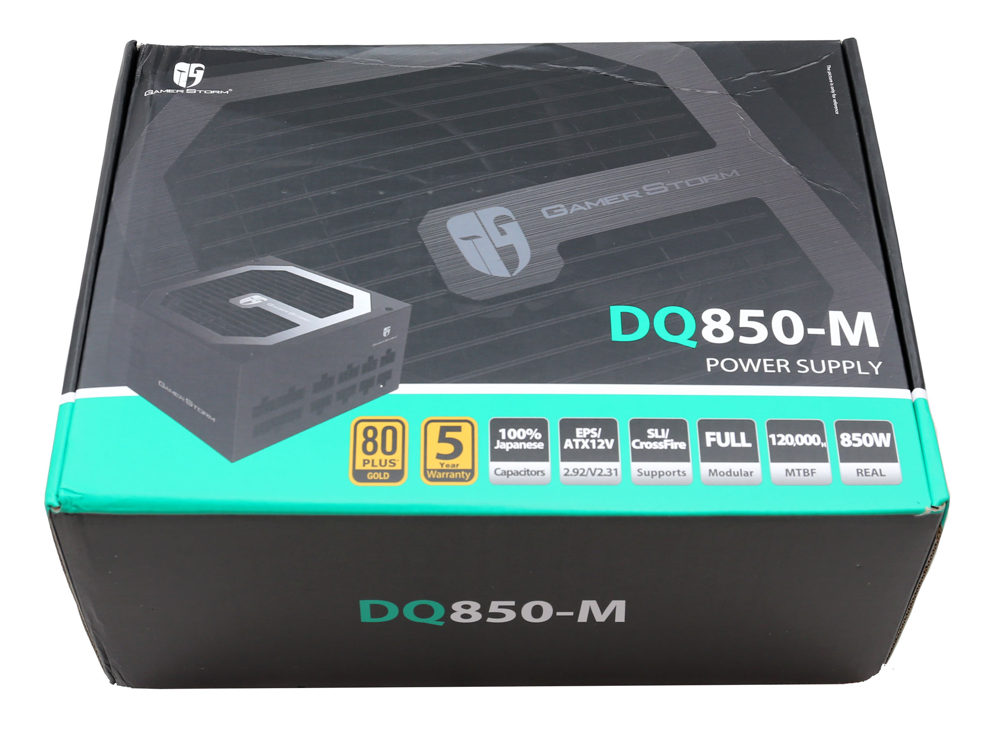
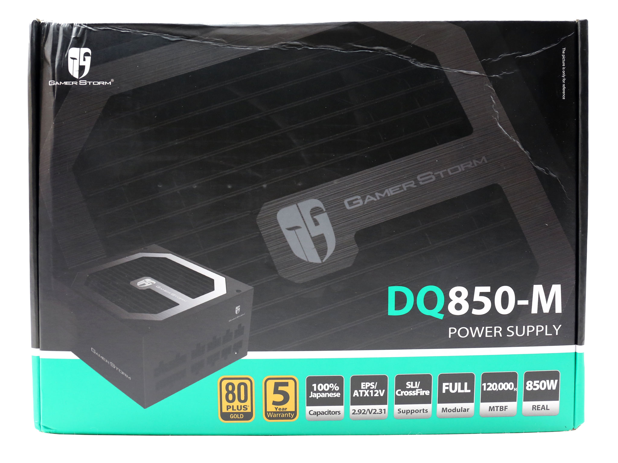
At the face of the box the majority of the real estate is taken by a photo of the fan grille. There is also a smaller, angled photo of the PSU with the modular panel on display. Right below the model number description is a large number of badges describing the 80 PLUS Gold efficiency, the five-year warranty (which has been extended to ten-years) and other interesting features.
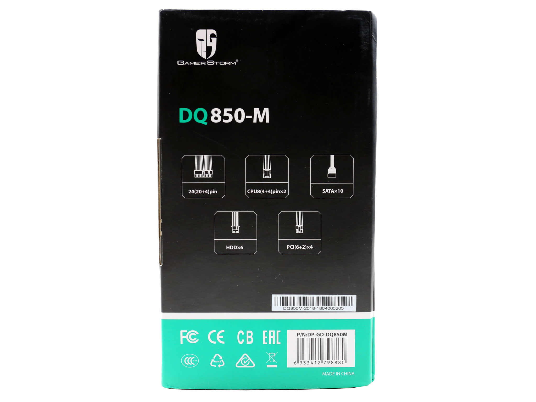
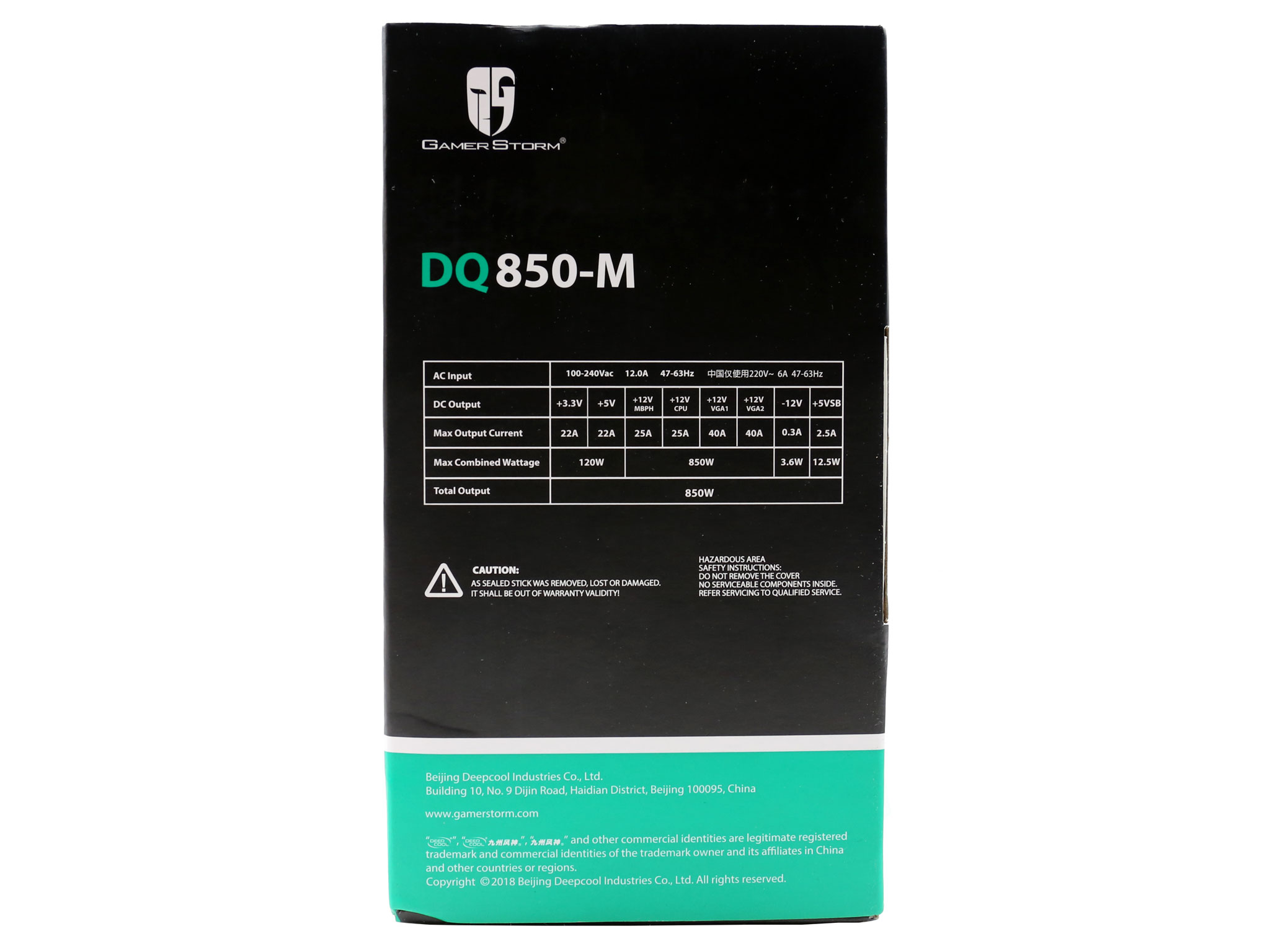
Onto one of the box's sides is a list of provided connectors, while on the opposite side is the power specifications table.

The rear of the box lacks detailed information about the platform or photos of the unit's internals. There is a features list here along with two graphs showing the unit's efficiency and the fan's speed curve.
Contents
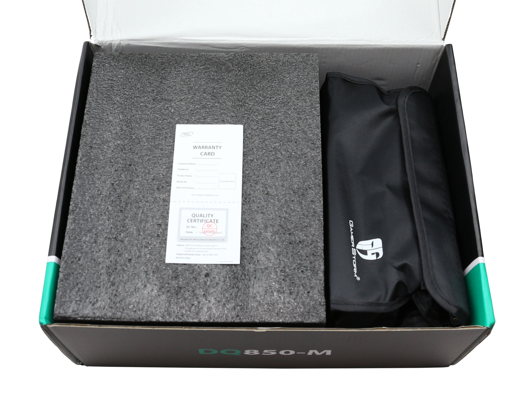
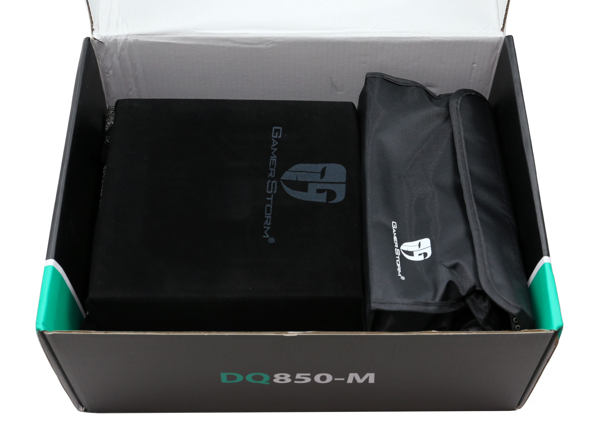
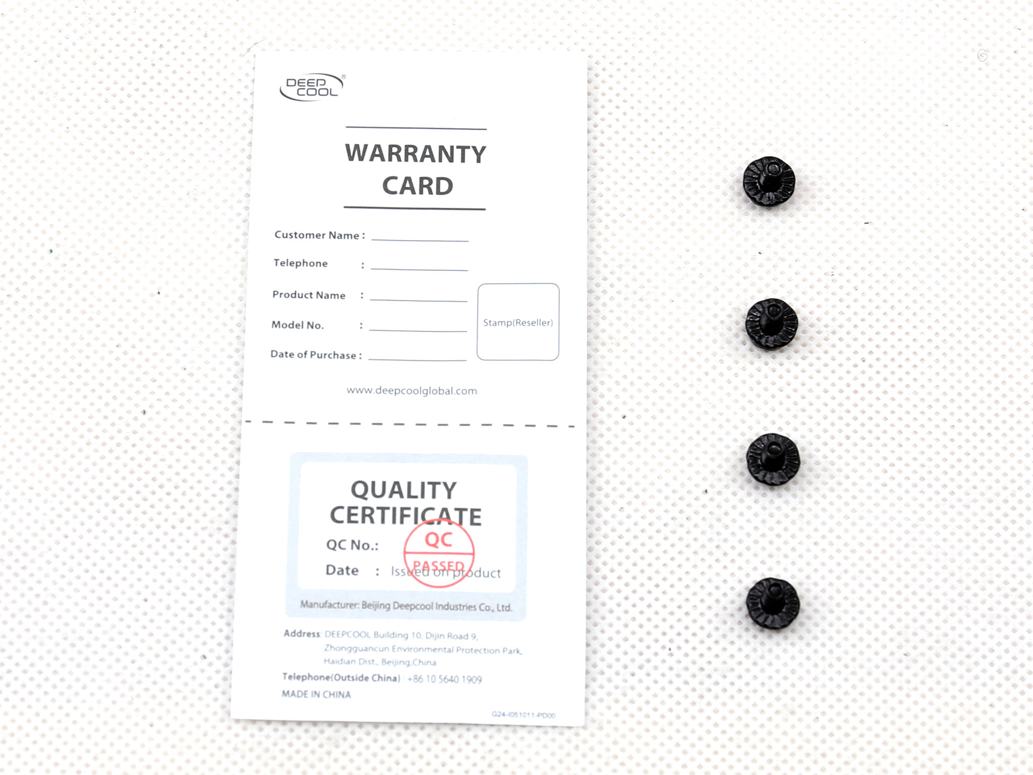
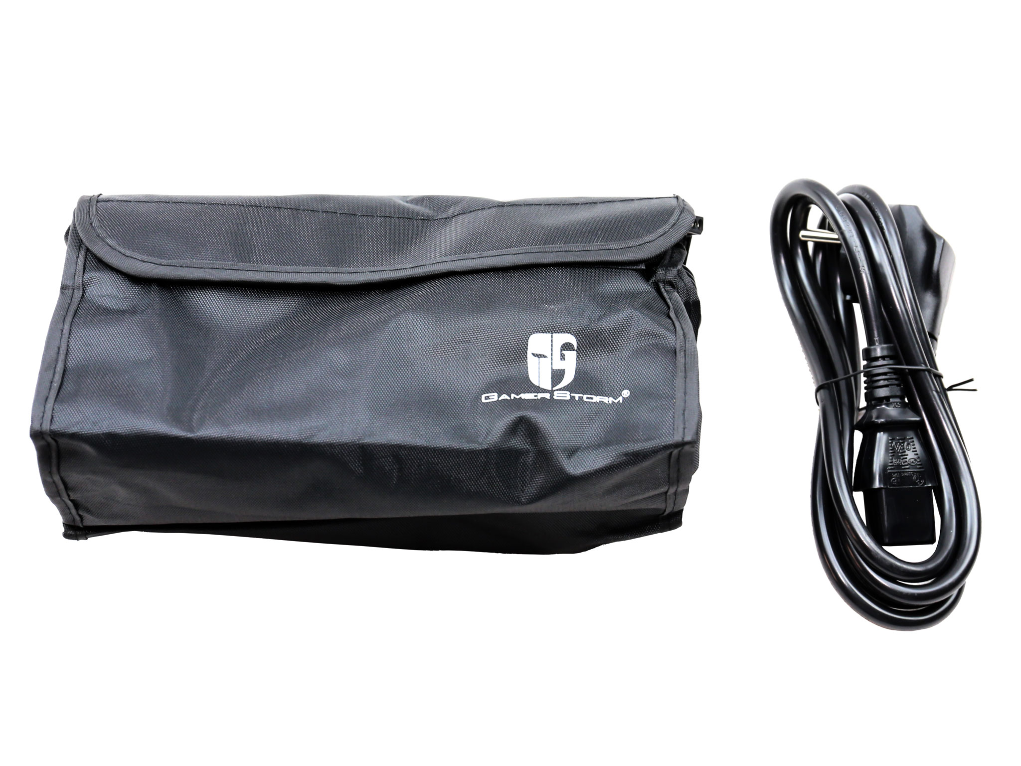
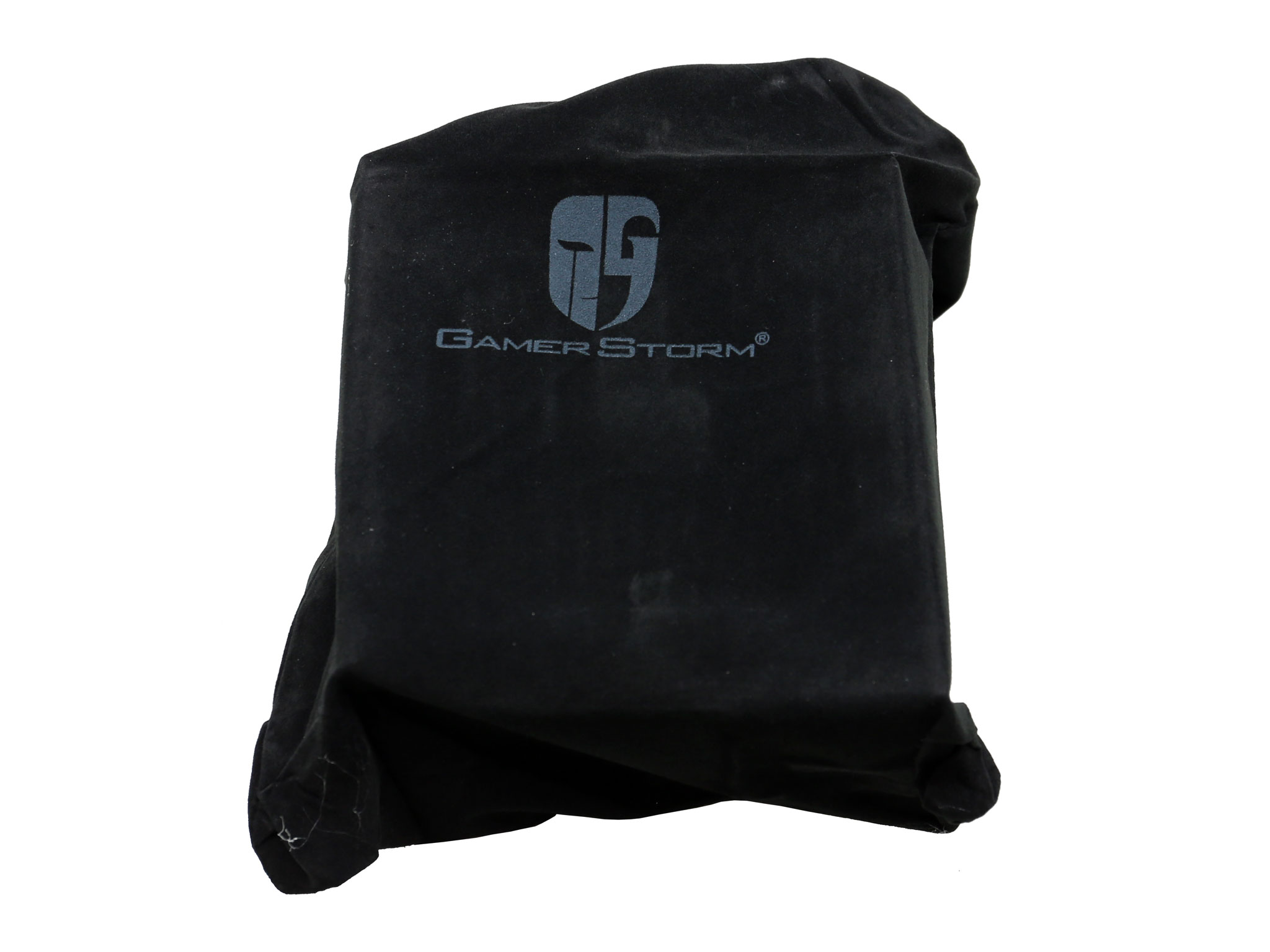
Two foam sheets surround the PSU into the box, providing adequate protection. The unit is also stored in a cloth bag. The bundle looks poor since it doesn't include any zip ties or velcro straps, or even a user's manual.
Exterior
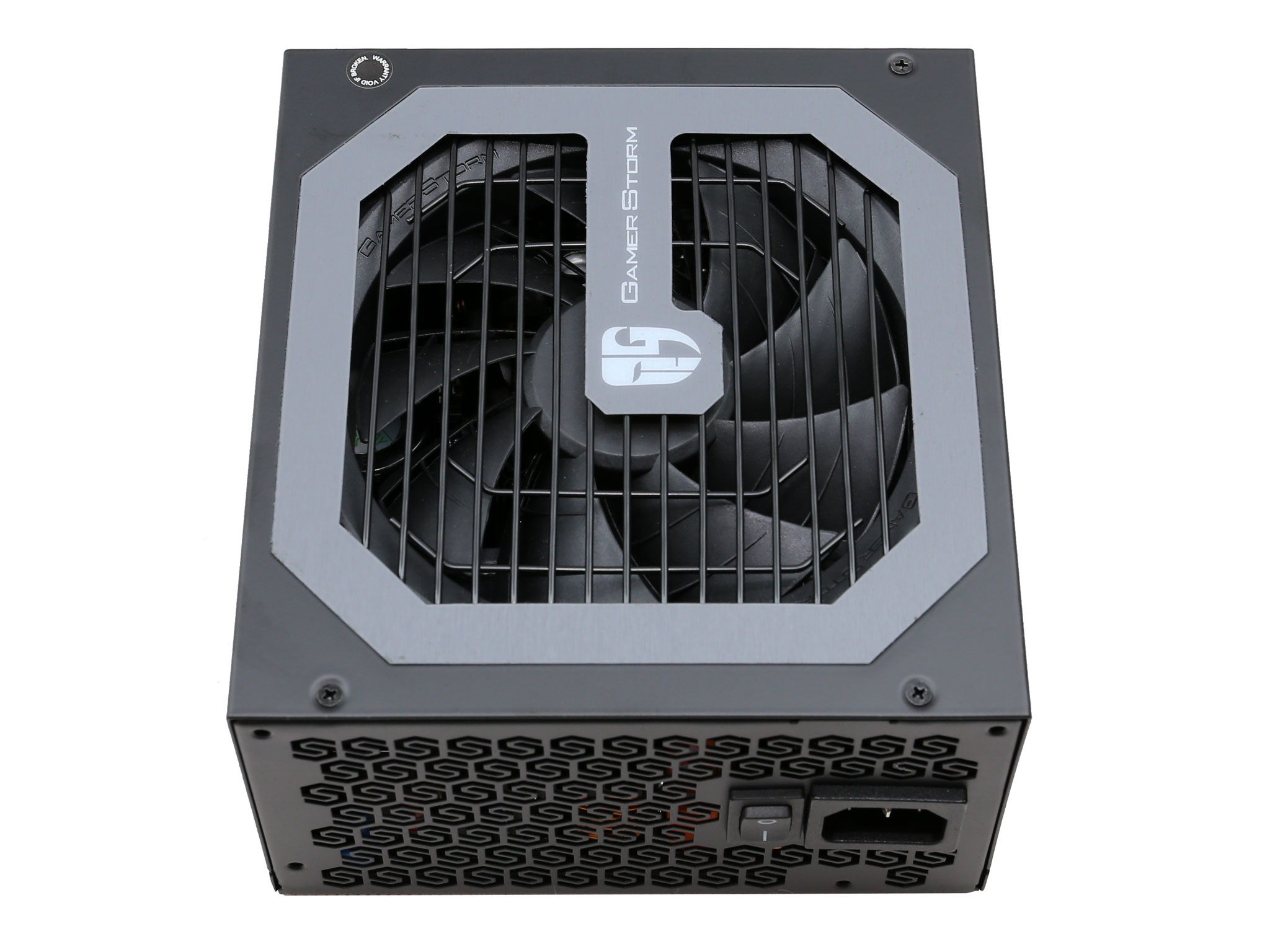
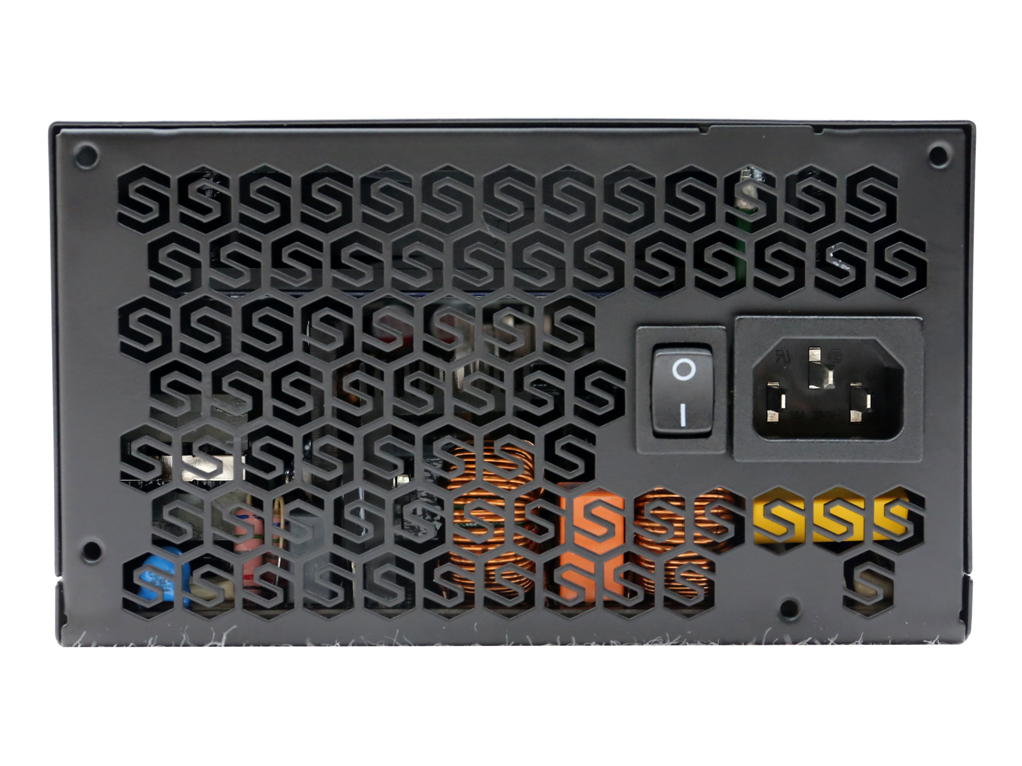
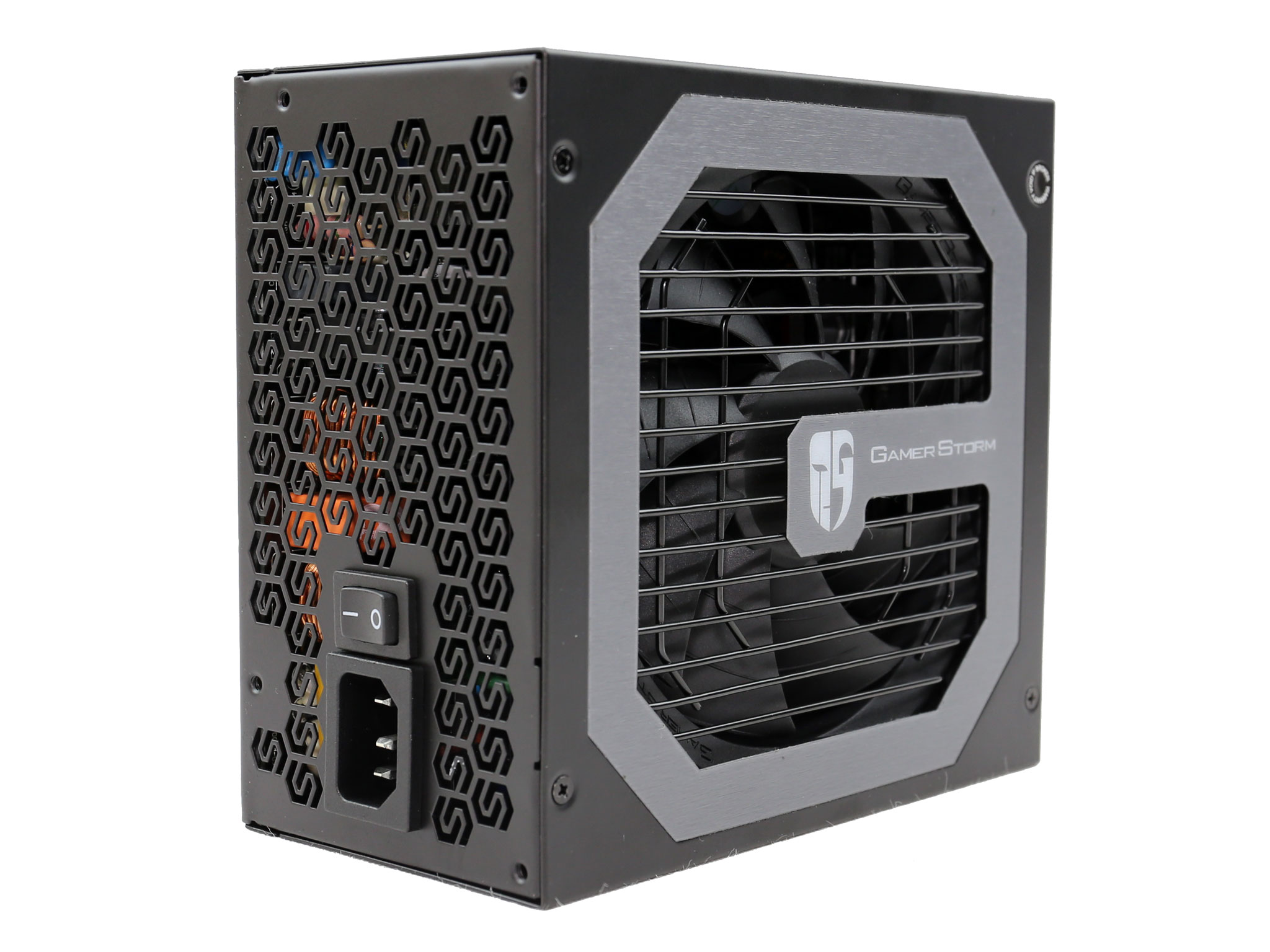
The front side (exhaust) doesn't use the typical honeycomb design perforations so it has a unique appearance. The same applies to the fan grille which looks nice. This PSU doesn't include a semi-passive mode, there is only a power switch and the AC receptacle of course, at the front.
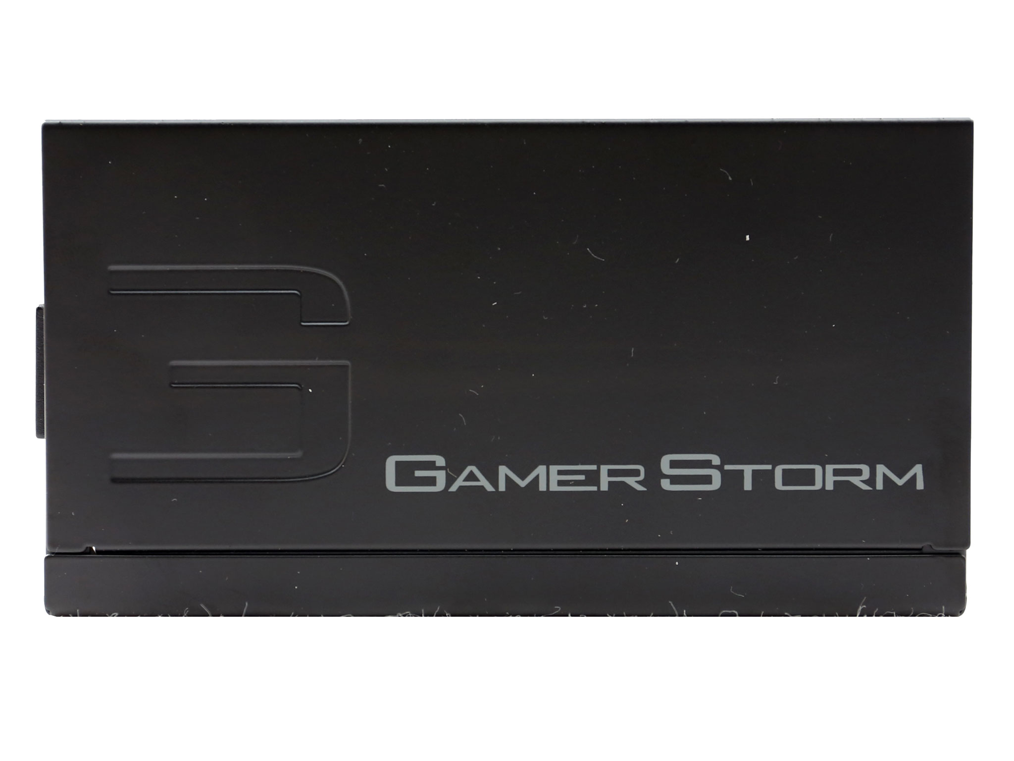
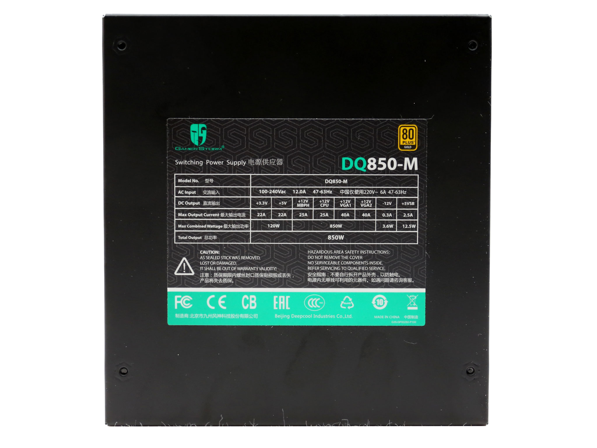
On the sides the stickers keep a very low profile. A much larger sticker is installed along the bottom, showing the power specifications table along with the model number, the 80 PLUS Gold badge and several other certification badges.
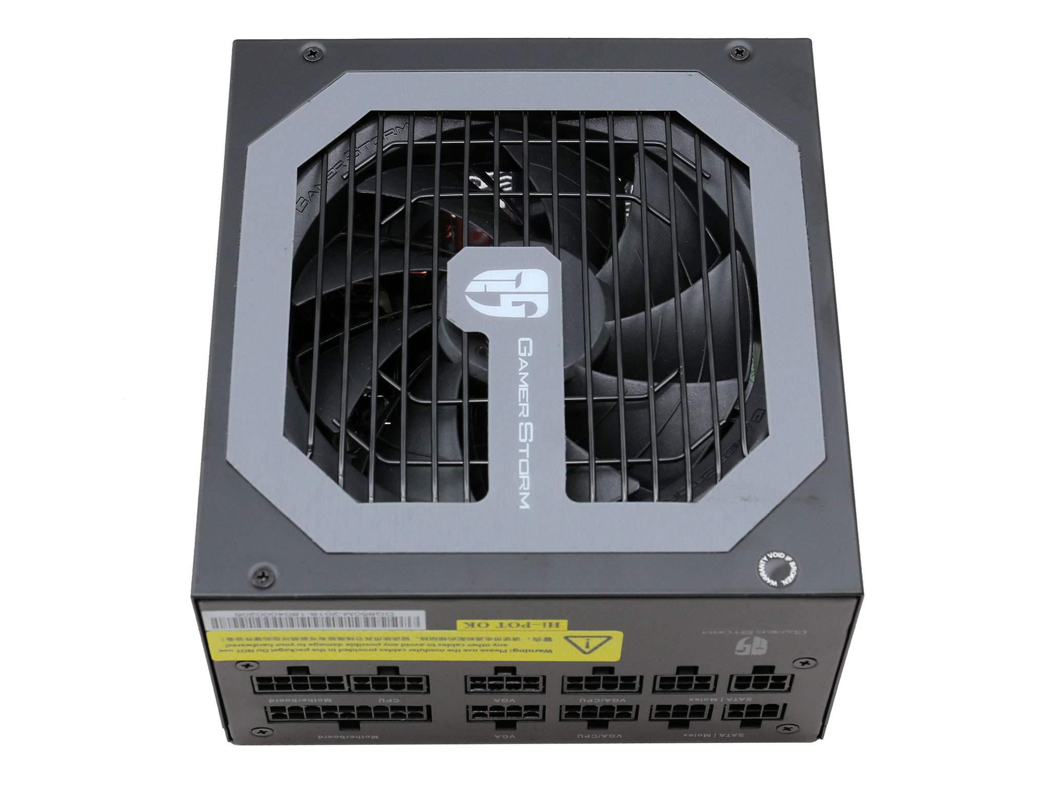
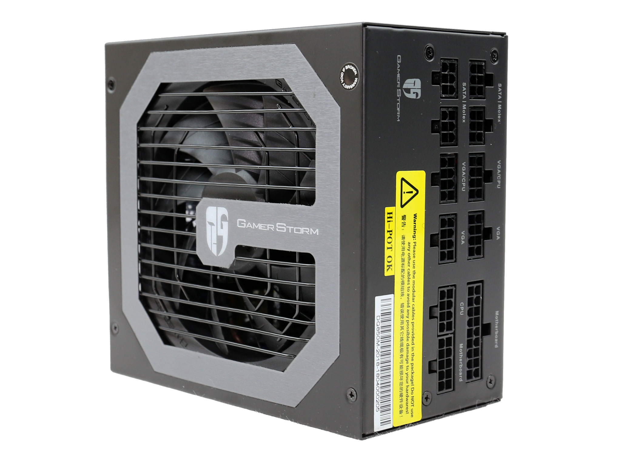
The modular panel includes eleven sockets. On this side we also find three stickers with one of them issuing a warning about not using other modular cables, only the ones provided with this product.
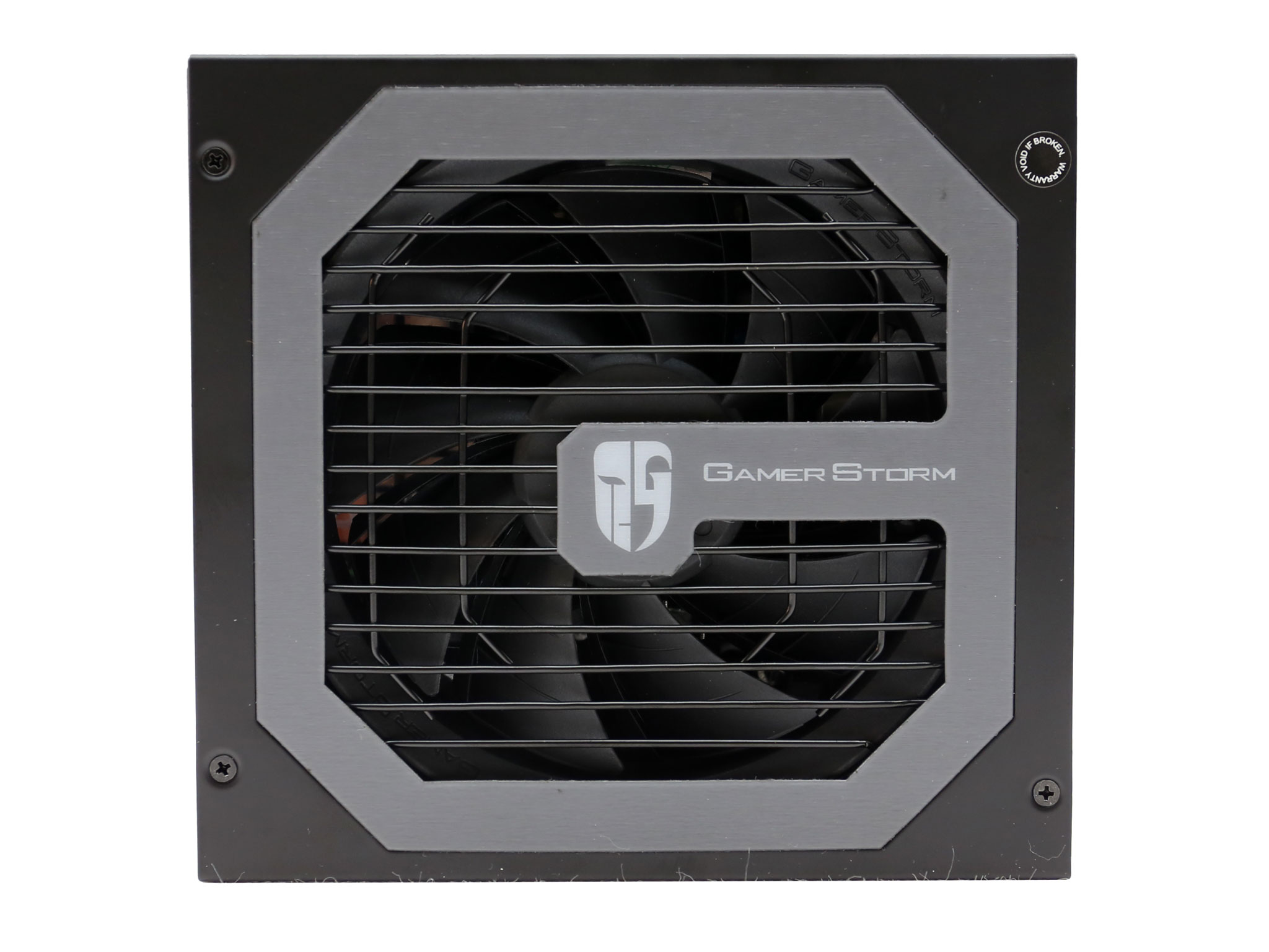
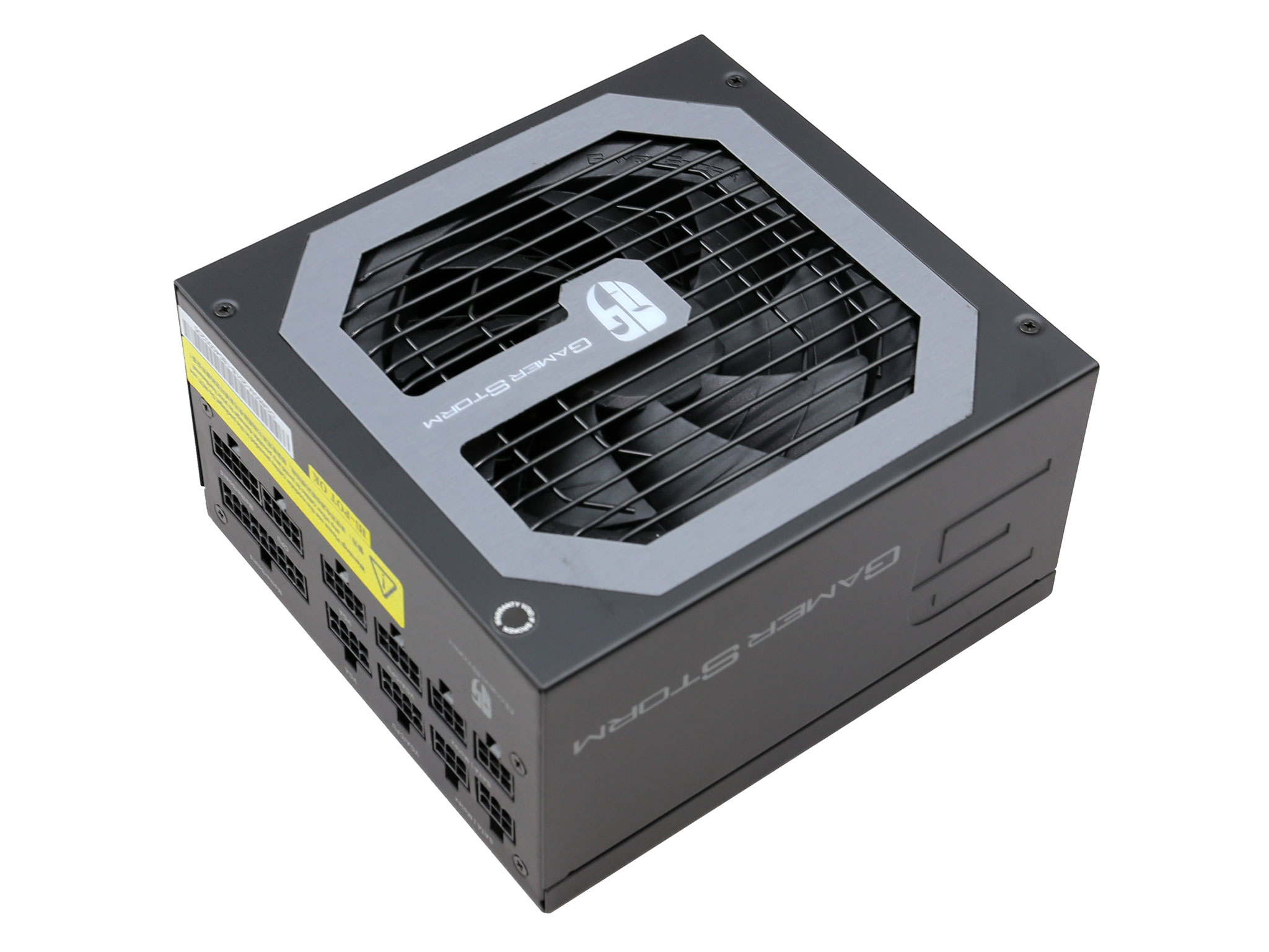
The large fan grille nicely covers the small diameter fan and it also allows for increased airflow.
| General Data | |
| Manufacturer (OEM) | CWT |
| Platform Model | GPU850V-G |
| PCB | Double Layer |
| Primary Side | |
| Transient Filter | 4x Y caps, 2x X caps, 2x CM chokes, 1x MOV, 1x CAP004DG |
| Inrush Protection | NTC Thermistor & Relay |
| Bridge Rectifier(s) |
1x GBU15L06 (600V, 15A @ 115°C)
|
| APFC MOSFETS |
2x Champion GP28S50G (500 V, 28A @ 150°C, 0.125 Ohm)
|
| APFC Boost Diode |
1x Infineon IDH08G65C5 (650V, 8A @ 145°C)
|
| Hold-up Cap(s) |
1x Nichicon (400V, 680uF, 2000h @ 105°C, GG)
|
| Main Switchers |
2x On Semiconductor FCPF125N65S3
(650V, 15A @ 100°C, 0.125Ohm) |
| APFC | Champion CM6502S & CM03X Green PFC controller |
| Switching Controller | Champion CM6901 |
| Topology |
Primary side: Half-Bridge & LLC Resonant Controller
Secondary side: Synchronous Rectification & DC-DC converters |
| Secondary Side | |
| +12V MOSFETS | 6x International Rectifier IRFH7004TR2PBF (40V, 164A @ 100°C, 1.4mOhm) |
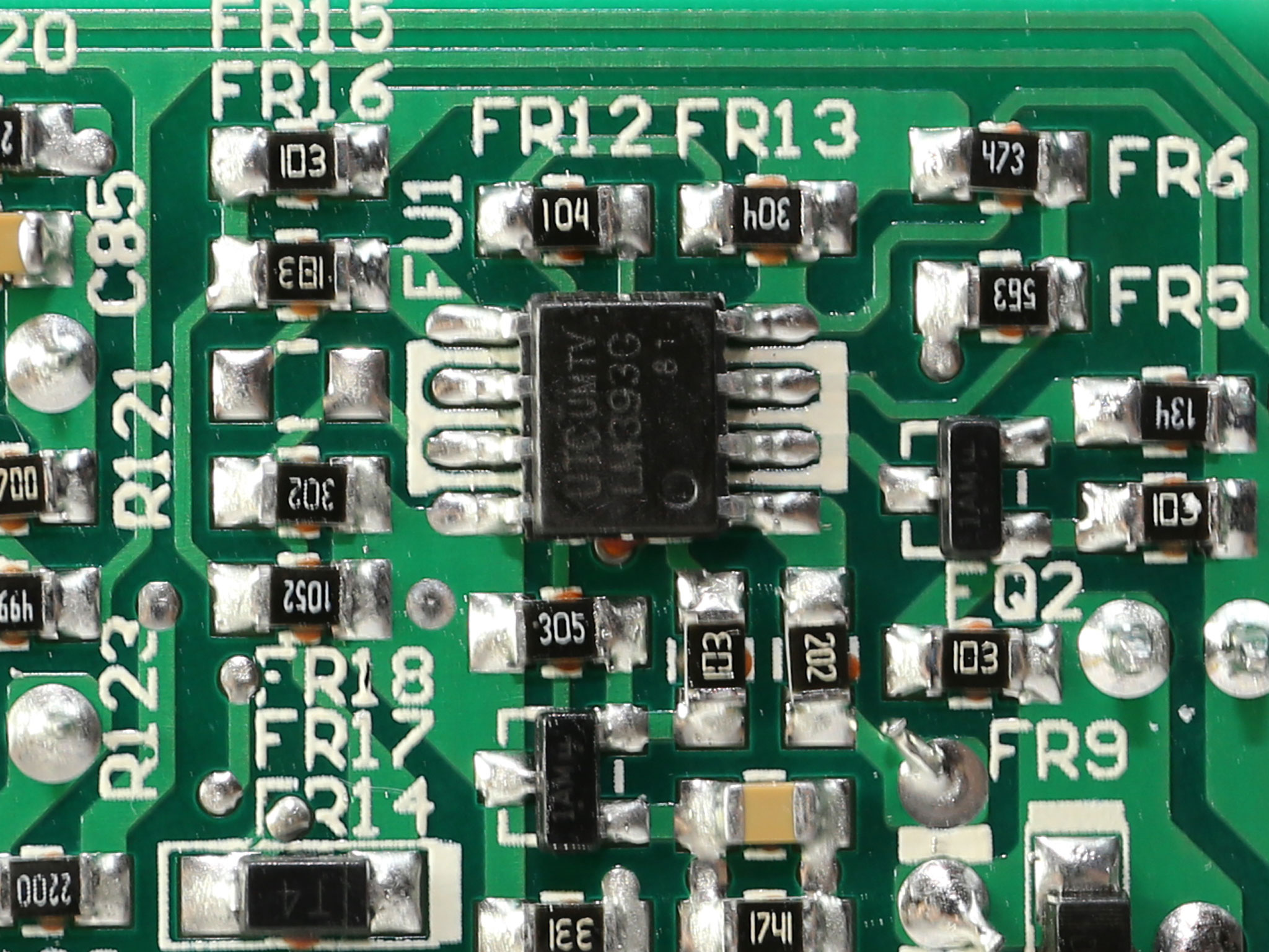
| 5V & 3.3V | DC-DC Converters: 2x UBIQ QM3006D FETs (30V, 57A @ 100°C, 5.5mΩ) 2x UBIQ QM3016D FETs (30V, 68A @ 100°C, 4mΩ) PWM Controller: ANPEC APW7159C |
| Filtering Capacitors | Electrolytics: Chemi-Con (4-10,000 @ 105°C, KY), Chemi-Con (1-5,000 @ 105°C, KZE), 2x Rubycon (6-10,000 @ 105°C, ZLH) Polymers: FPCAP |
| Supervisor IC | Sytronix ST9S429-PG14 (OCP [2x 12V channels, OVP, UVP, PG) & Weltrend WD7518D (OCP [2x 12V channels], SCP) & LM393G |
| Fan Model | Deepcool DF1202512CH-003 (120mm, 12V, 0.15A, Fluid Dynamic Bearing) |
| 5VSB Circuit | |
| Standby PWM Controller | TinySwitch-LT TNY177PN (18W Peak) |
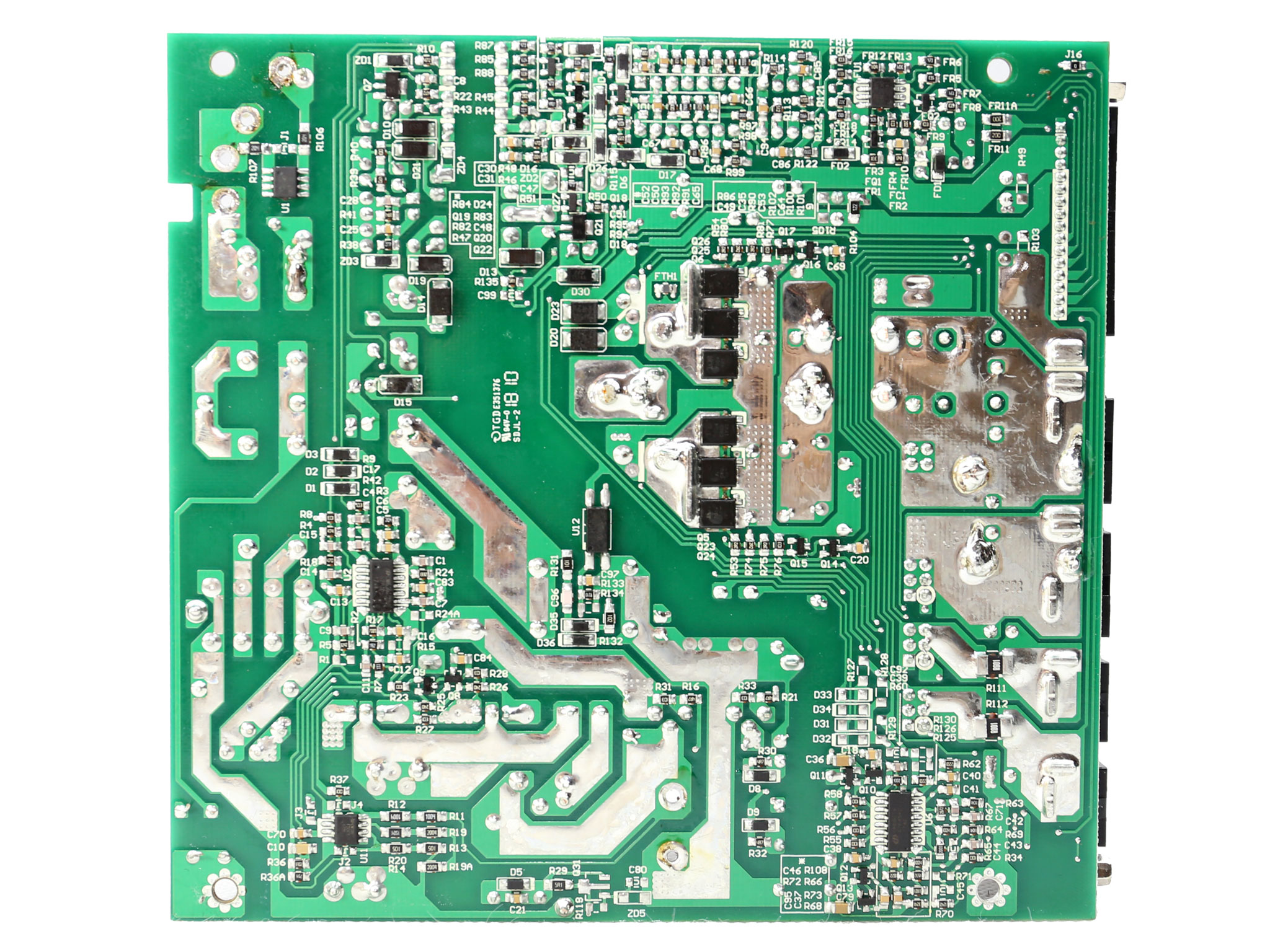
The platform is provided by CWT and it is actually based on the GPU850V-G, with several modifications in order to make it more reliable and slightly improve the performance. For example all capacitors are of higher quality since they are sourced by Japanese manufacturers, both the electrolytic and polymer ones.
In the primary side a half-bridge topology is used along with a LLC resonant converter for higher efficiency. In the secondary side six FETs regulate the +12V rail and a pair of DC-DC converters handle the generation of the minor rails.
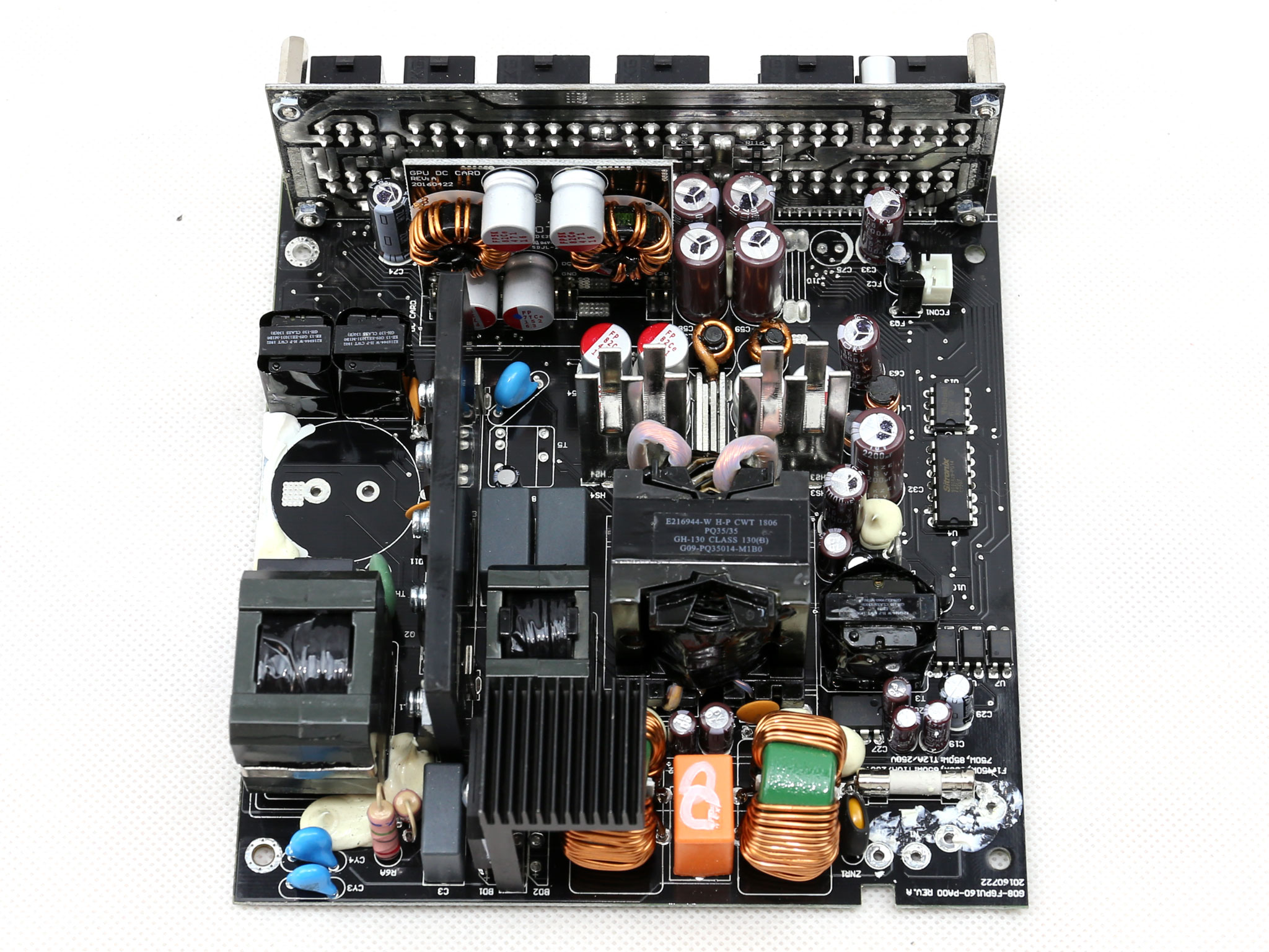
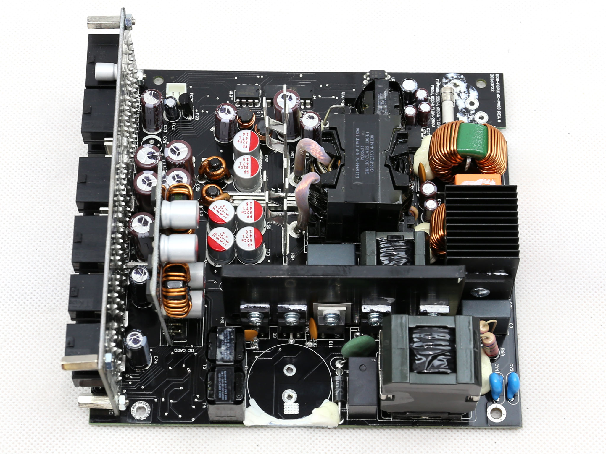
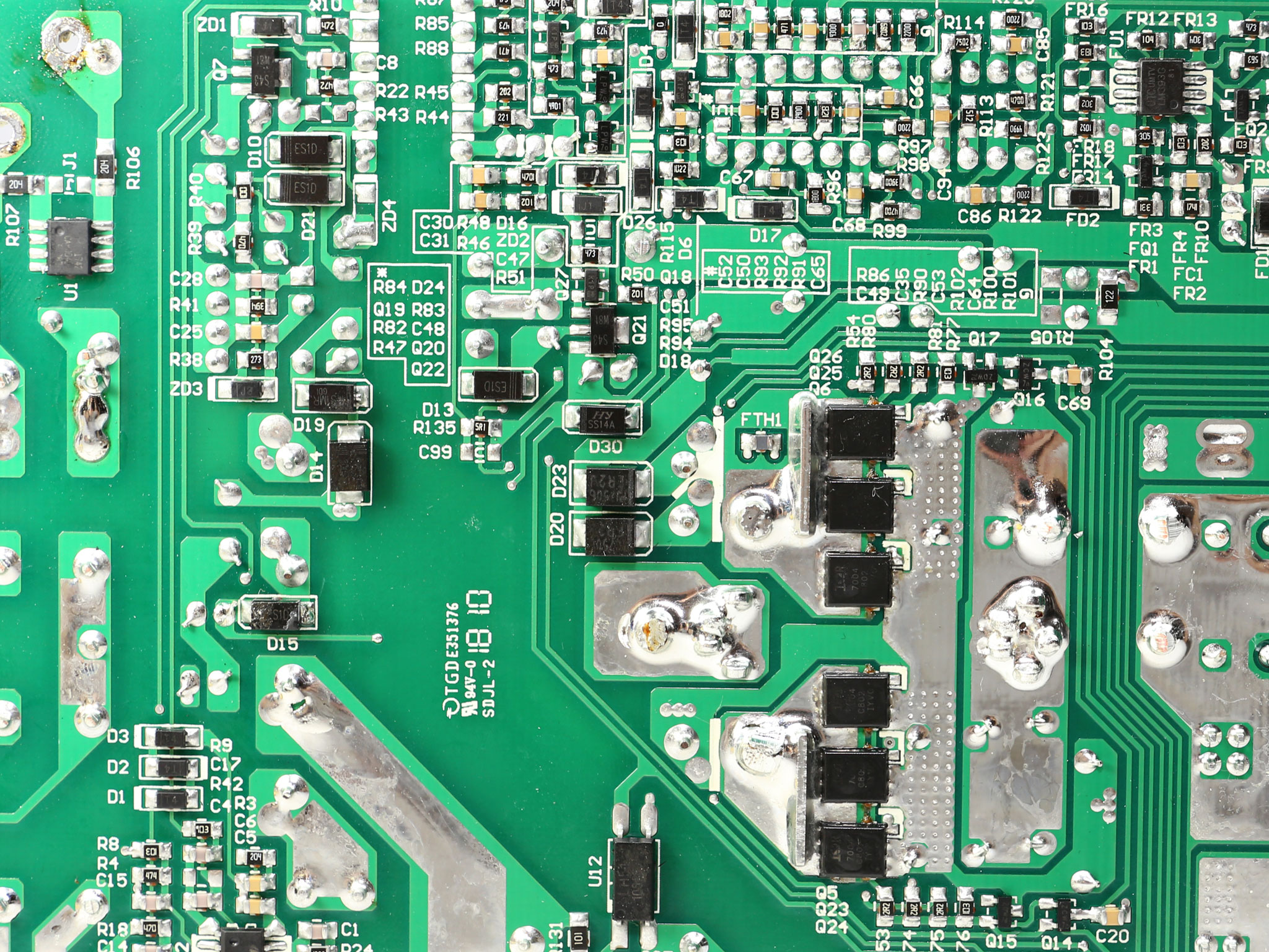
The build quality is good, something expected since this is a high-end CWT platform. It is also expected from a high efficiency CWT platform to barely use any heatsinks and indeed this is the case here.
In the secondary side we only find two small heatsinks with no components attached on them, while in the primary side the APFC converter's heatsink is small.
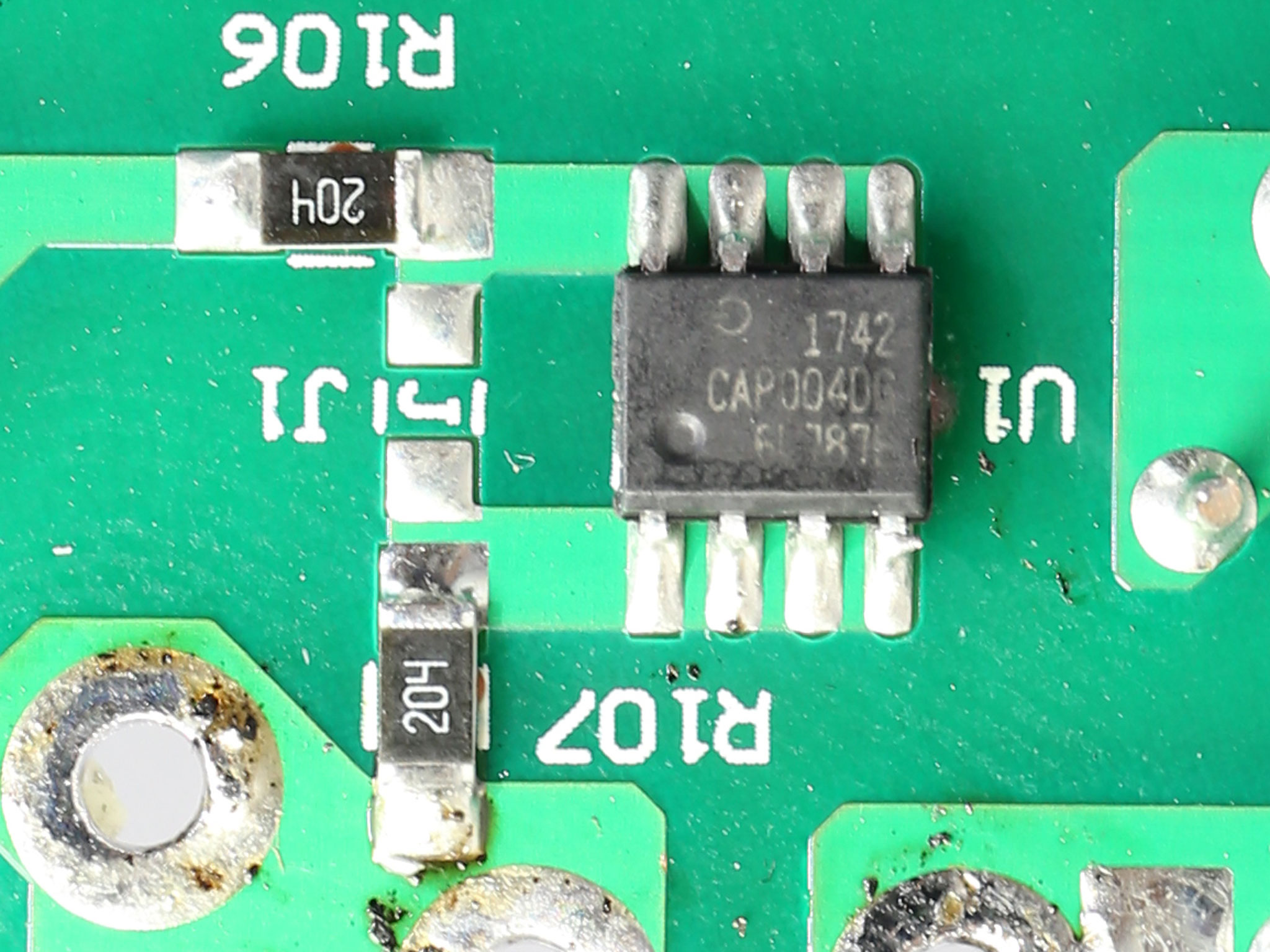
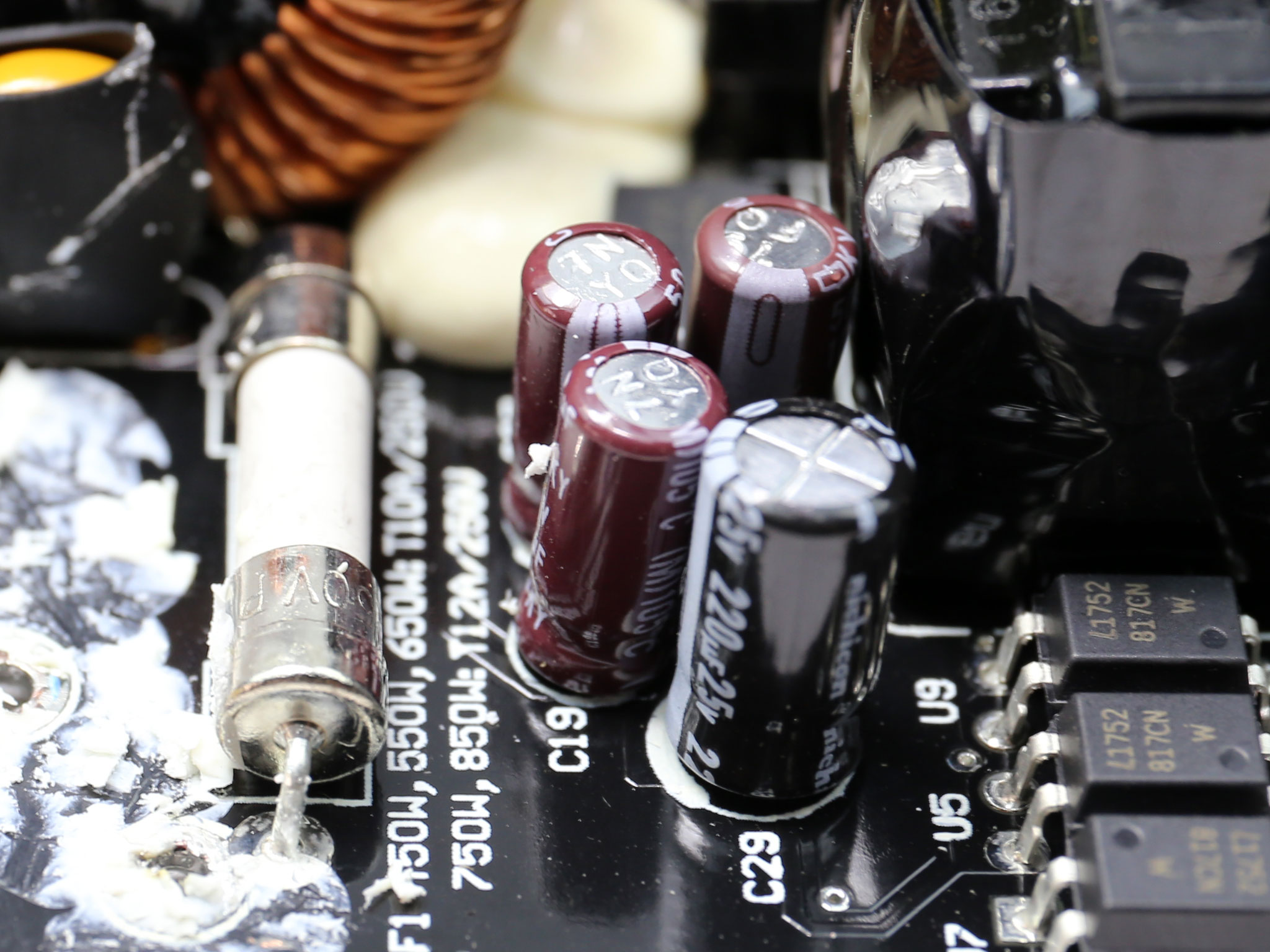
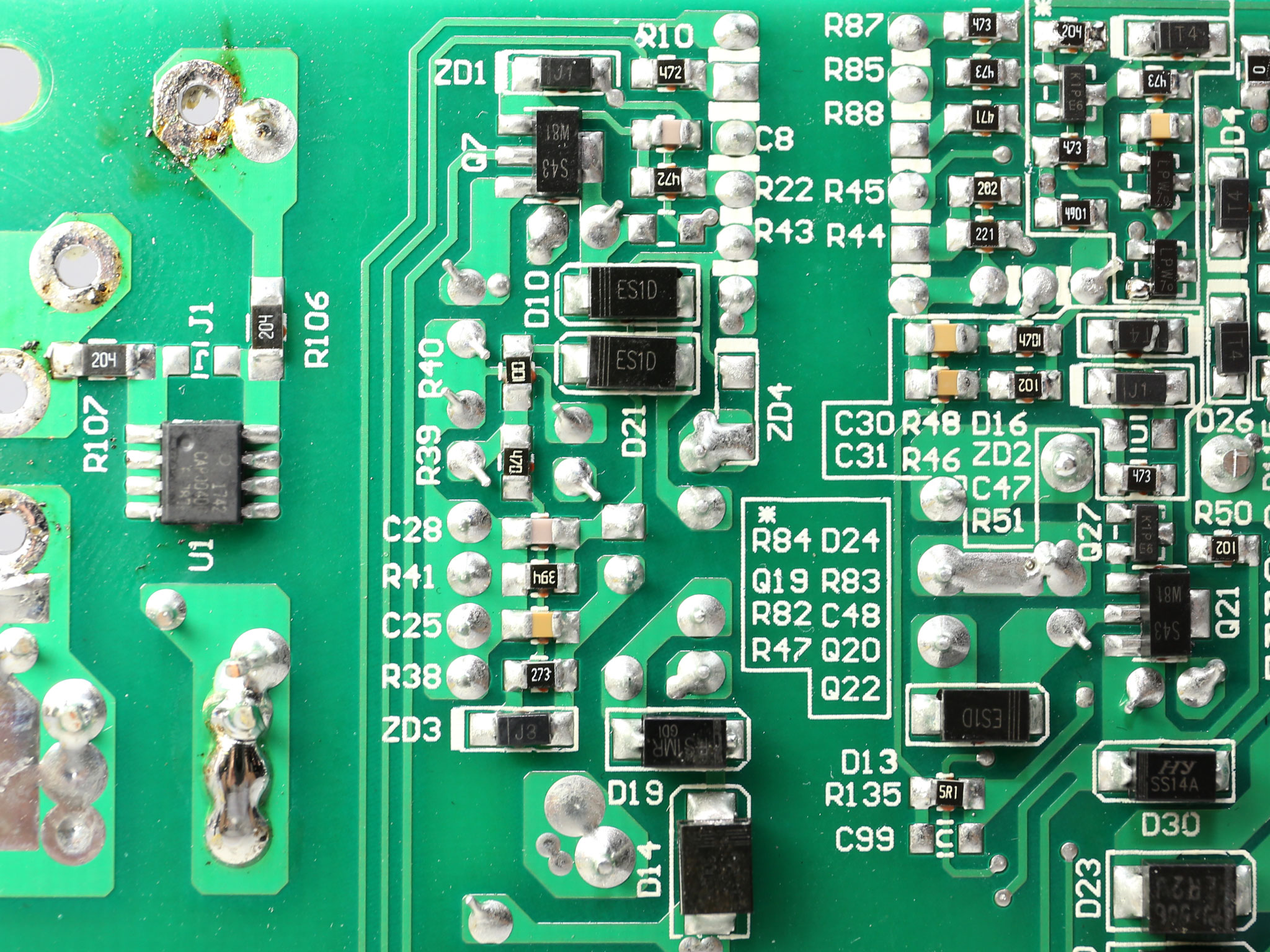
The first part of the EMI filter consists of two Y and one X caps. The second part includes more parts: two Y caps installed after the bridge rectifier, a single X cap, an MOV and a CAP004DG discharge IC. All in all the EMI filter is complete and does a splendid job.
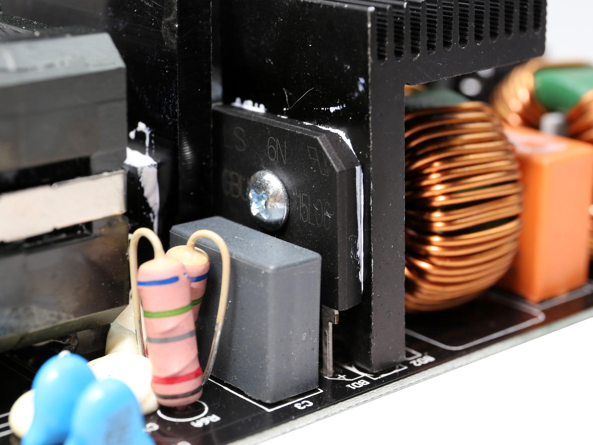
The single bridge rectifier, a GBU15L06, is installed onto a dedicated heatsink.
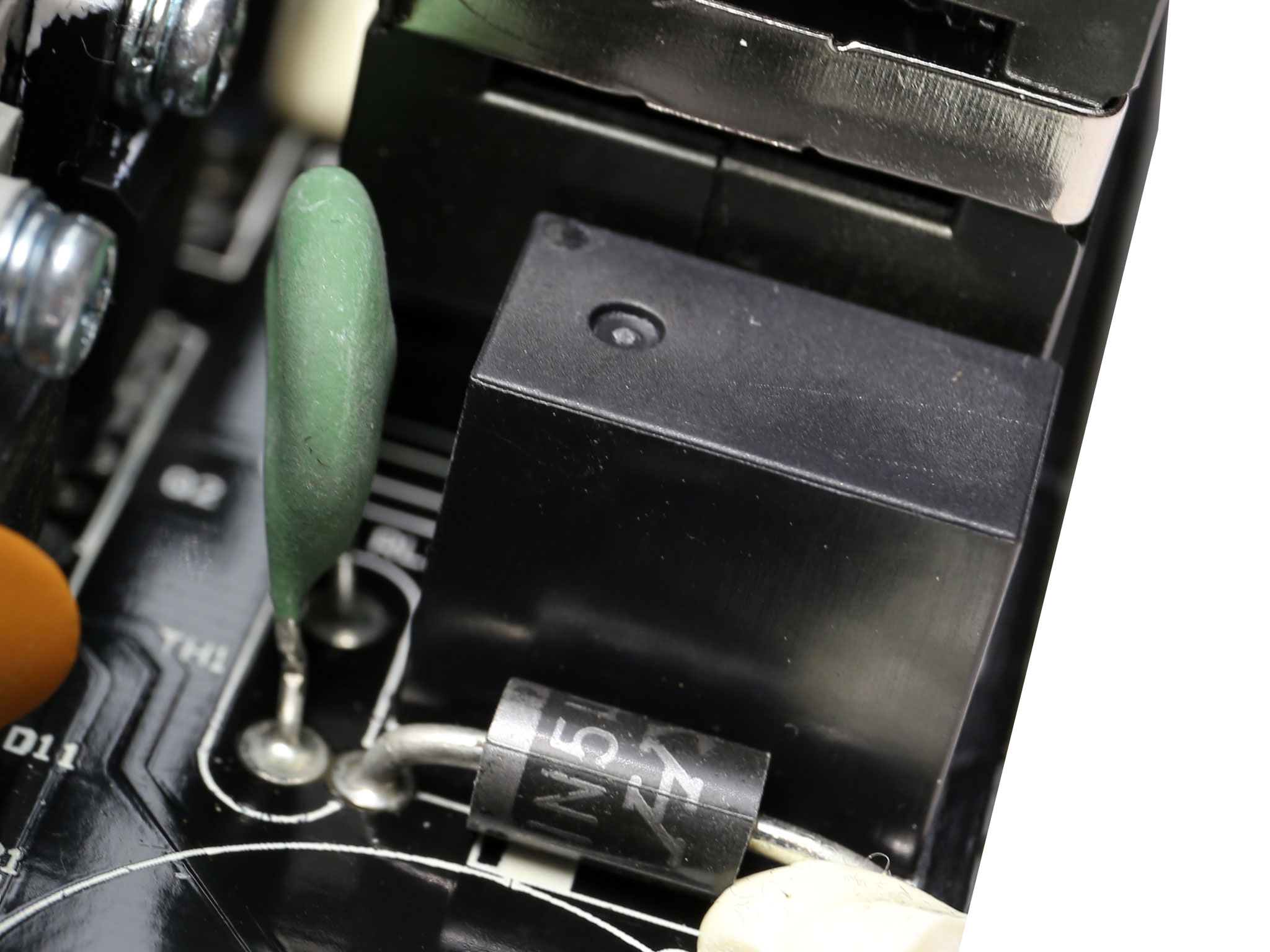
The NTC thermistor, responsible for protection against large inrush currents, is supported by a bypass relay.
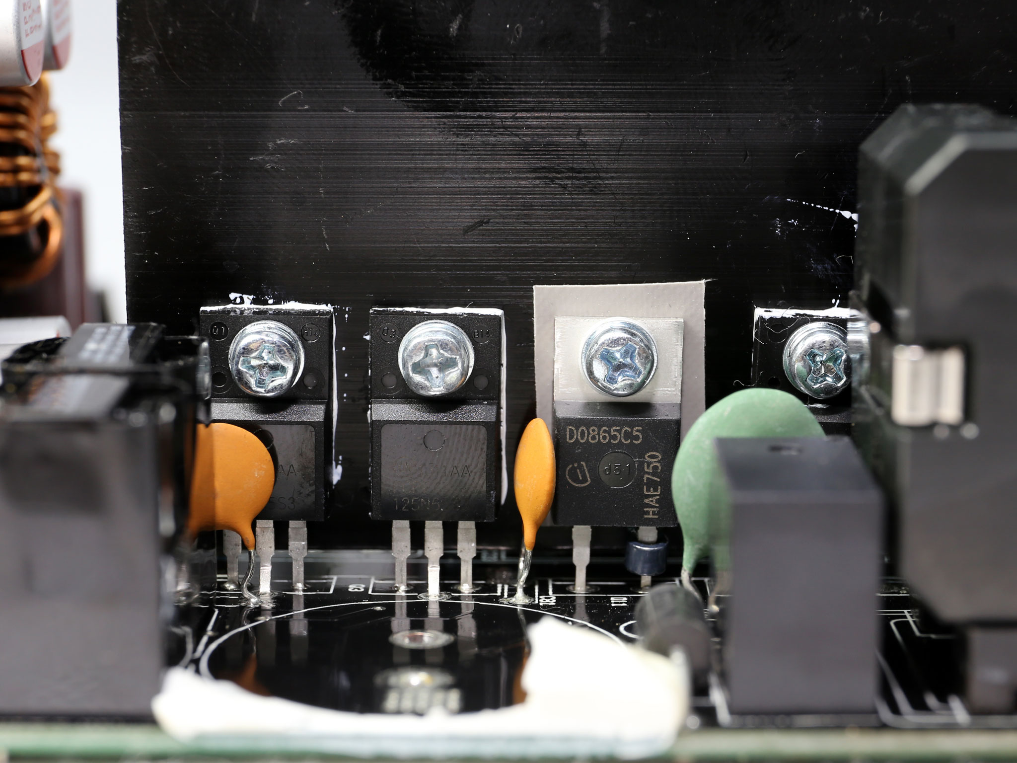
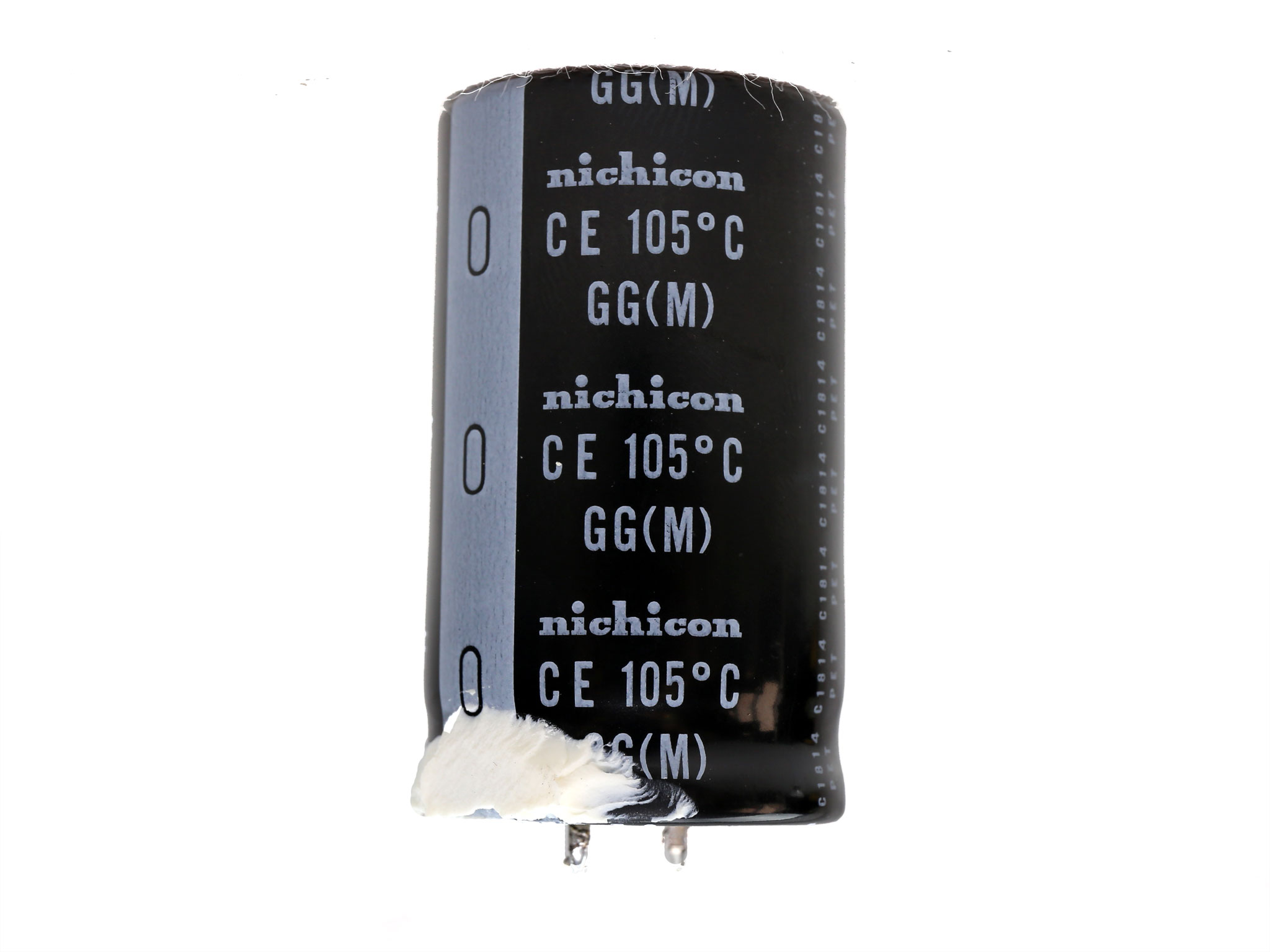
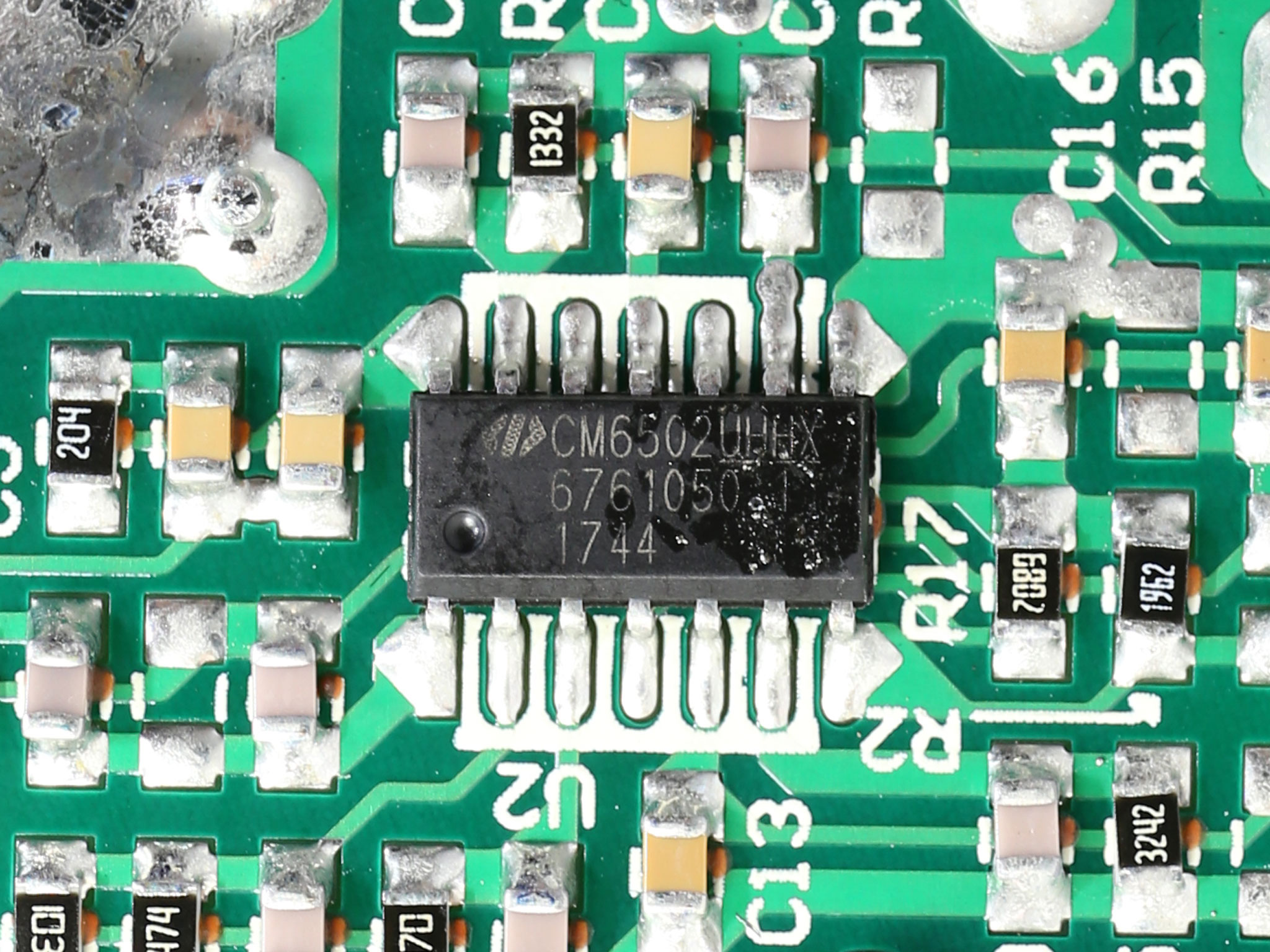
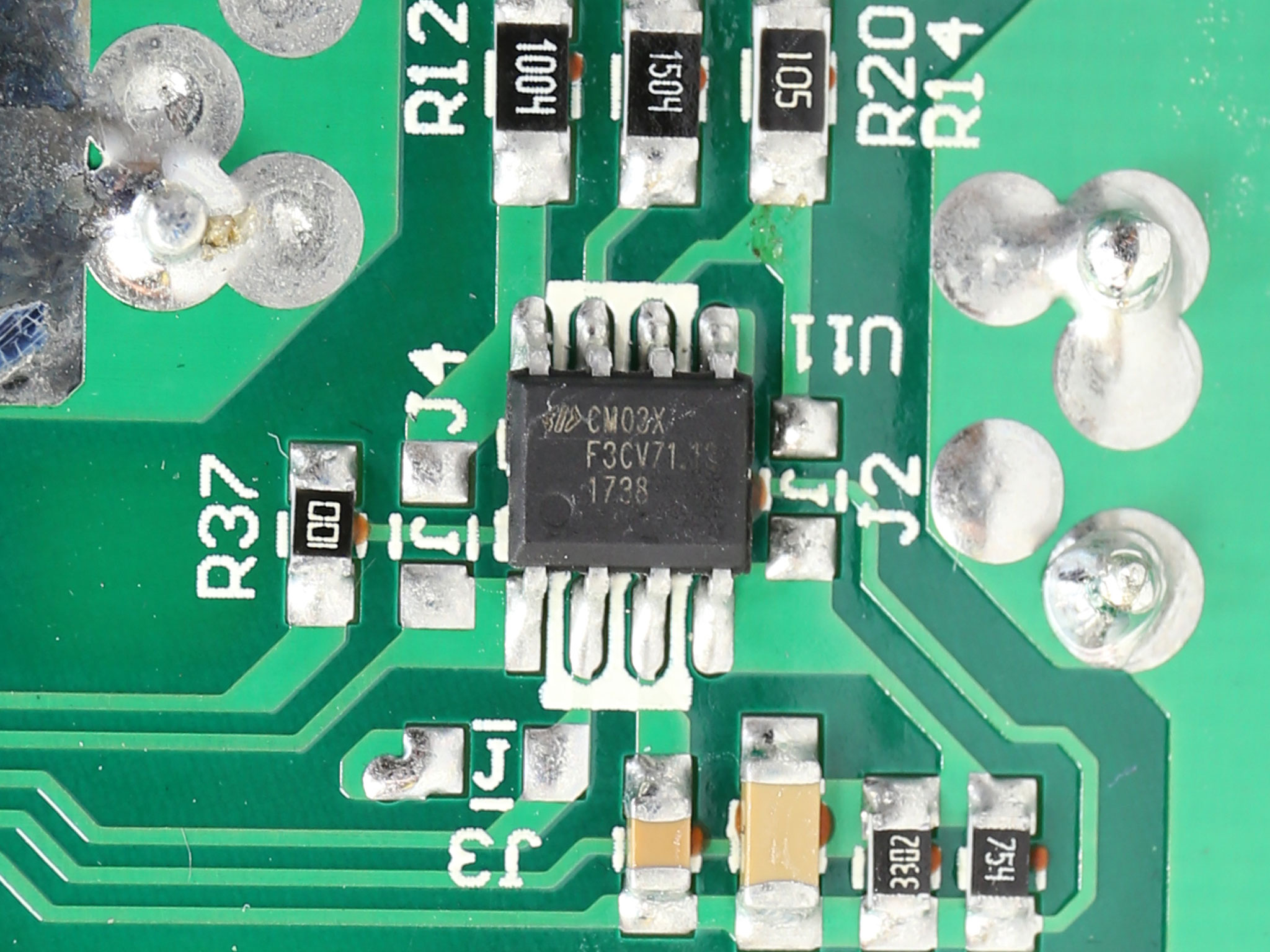
The APFC converter uses two Champion GP28S50G FETs and a single Infineon IDH08G65C5 boost diode. The bulk cap is provided by Nichicon and its capacity, 680uF, is low for a 850W unit. This means that the hold-up time is lower than 17ms. The APFC controller is a Champion CM6502S which is also supported by a CM03X Green PFC controller.
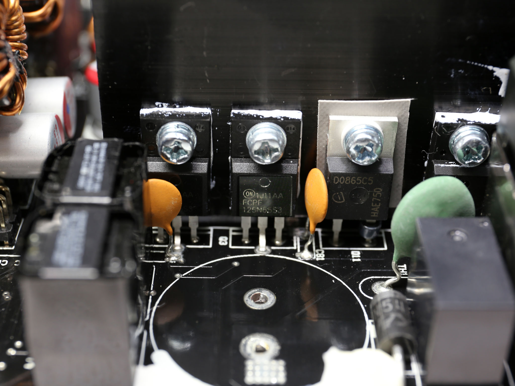
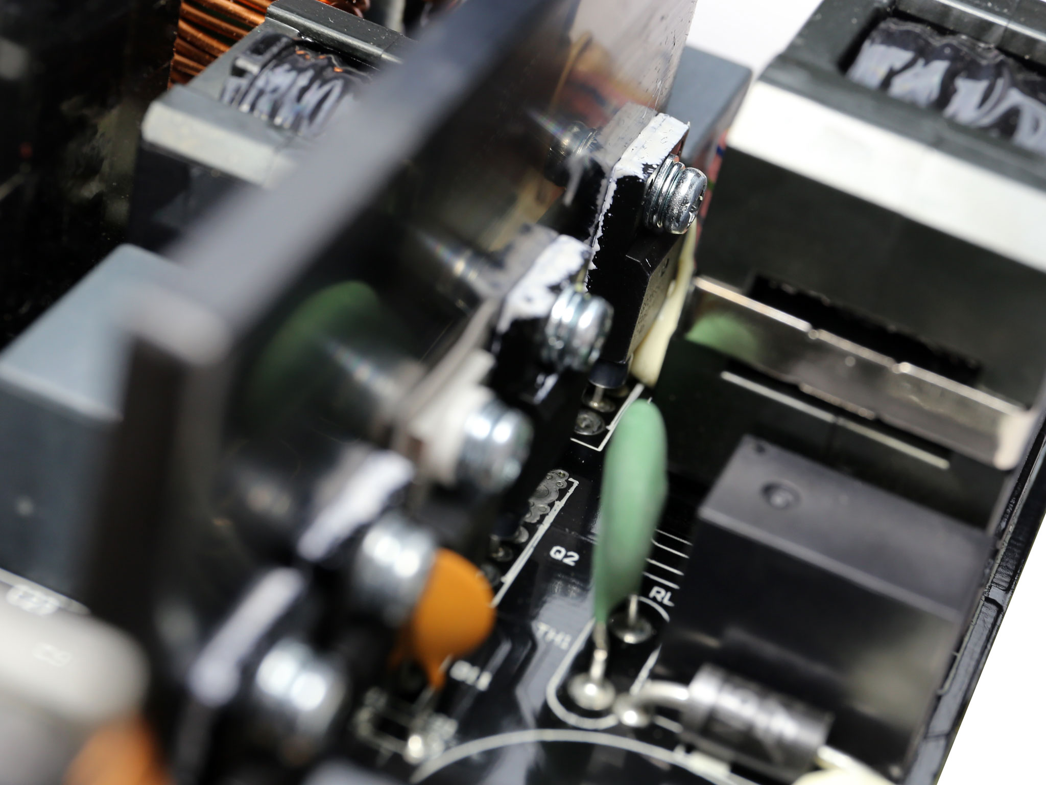
The primary switching FETS, two On Semiconductor FCPF125N65S3, are installed into a half-bridge topology. An LLC resonant is also utilized to offer lossless switching.
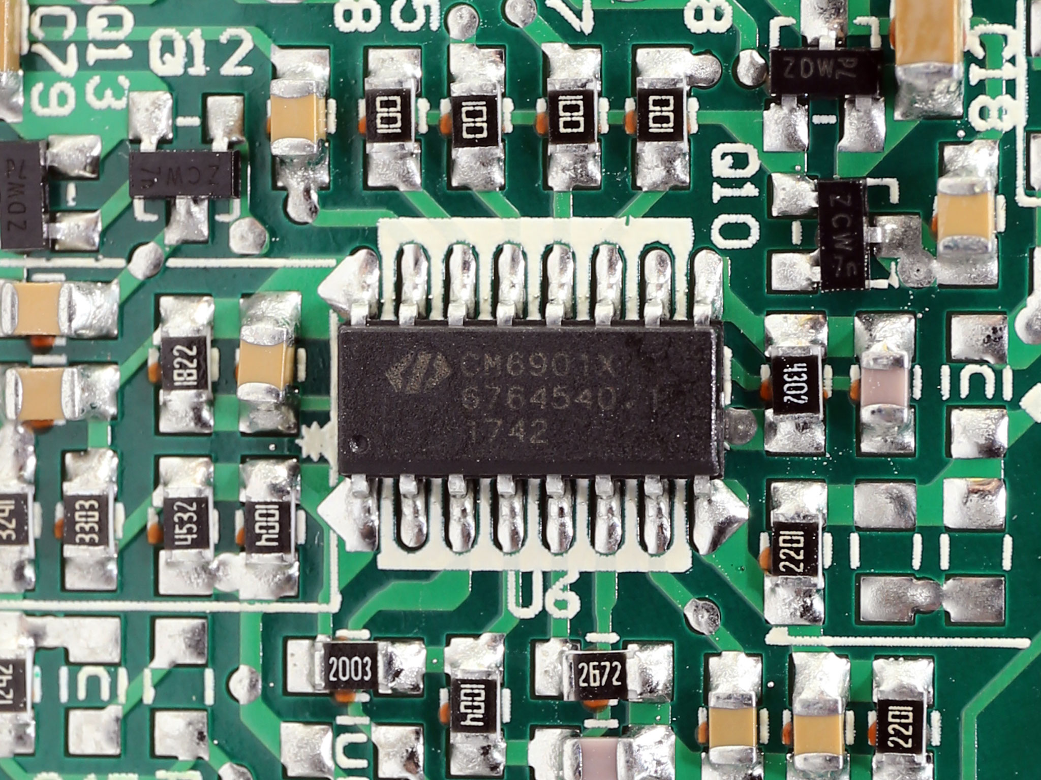
The IC responsible for controlling all above, along with the switching of the +12V FETs, is a Champion CM6901. The latter is installed on the solder side of the main PCB.
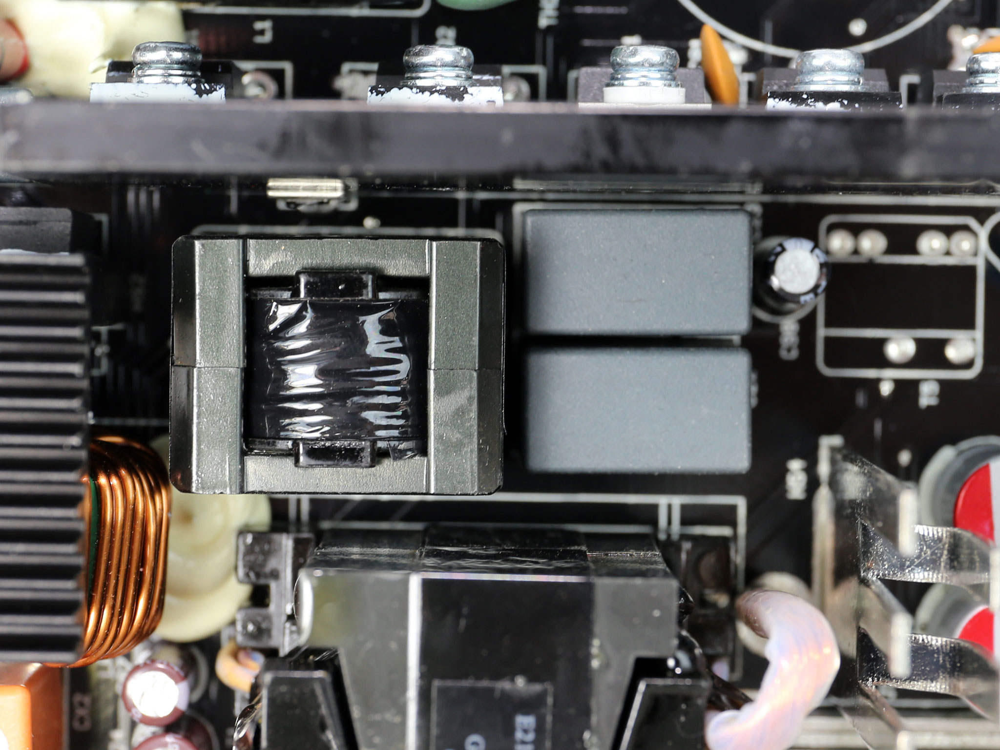
![]()
The unit's main transformer.
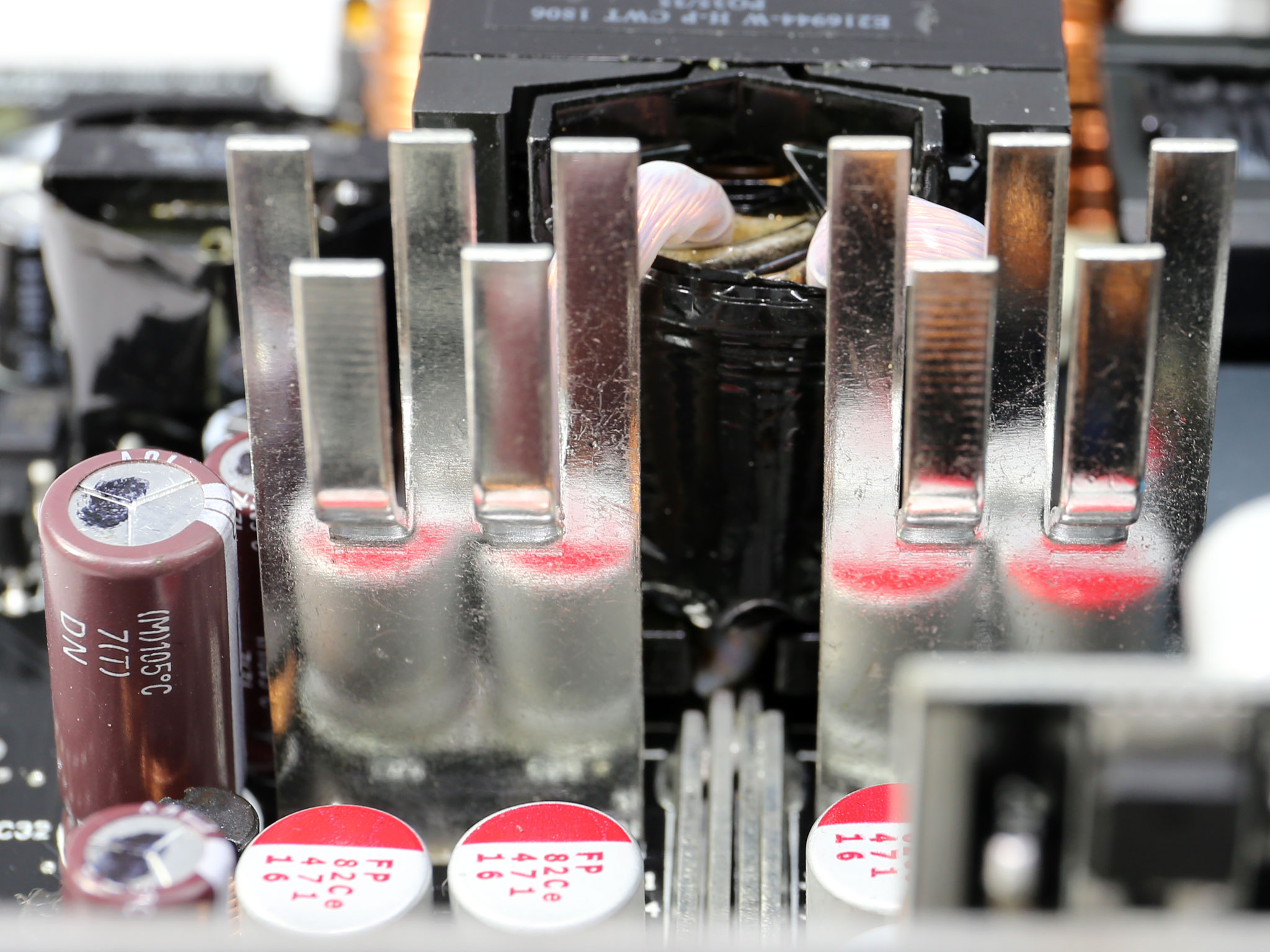
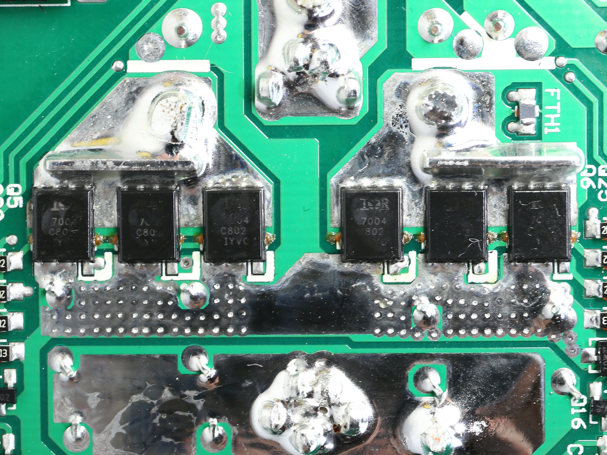
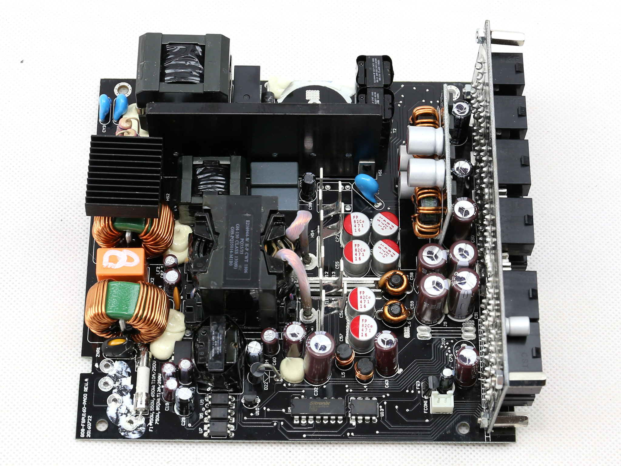
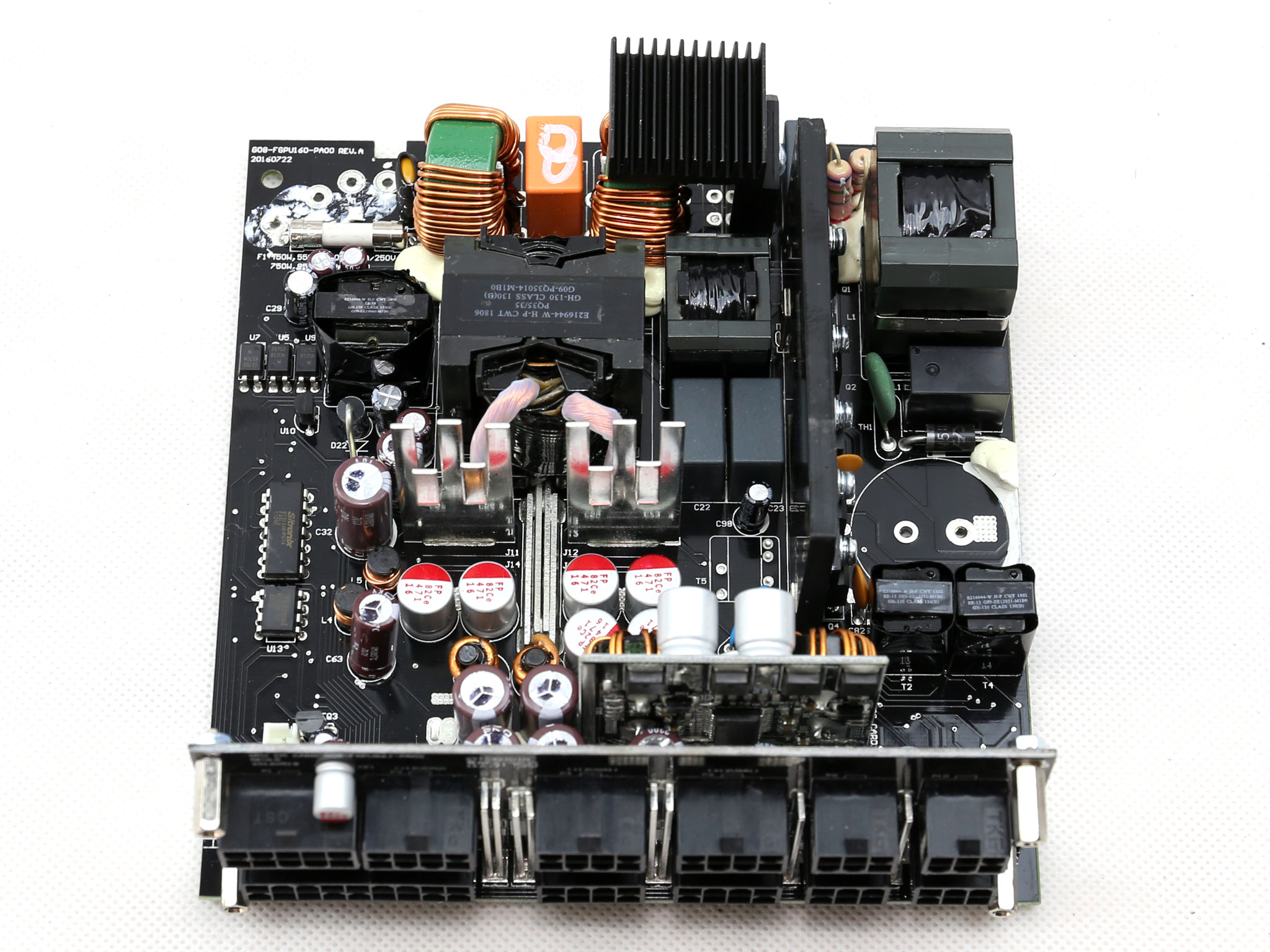
There are two small heatsinks in the secondary side, which don't host any parts. Their main job is to cool down the FETs located at the solder side of the PCB, six International Rectifier IRFH7004TR2PBF which handle the +12V rail.
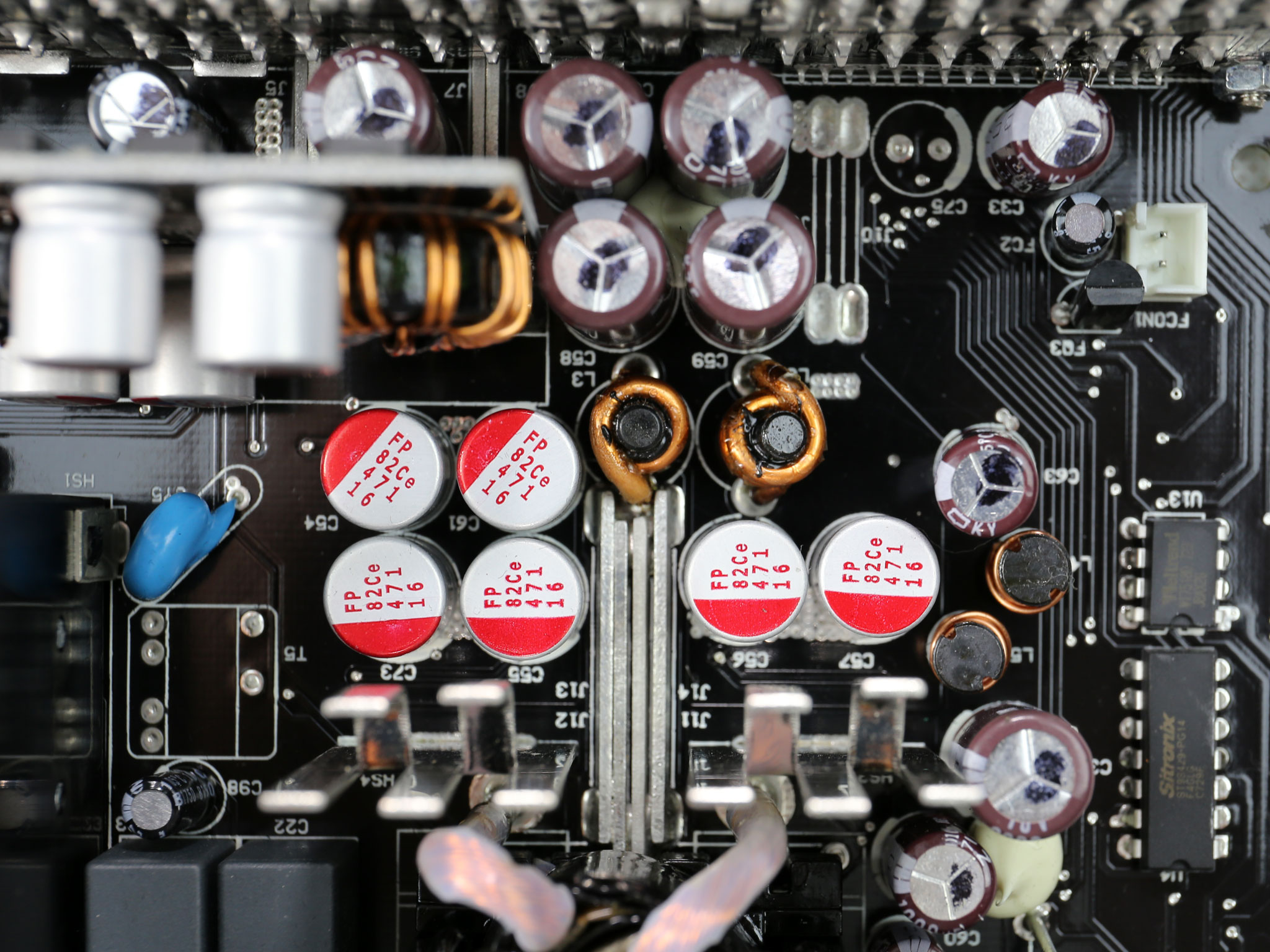
All filtering caps, both electrolytic and polymer ones, are provided by Japanese manufacturers (Chemi-Con KZE and KY, Rubycon ZLH and FPCAP).
A couple of VRMs generate the minor rails. They use two UBIQ QM3006D and two QM3016D FETs, while the common PWM controller is a ANPEC APW7159C.
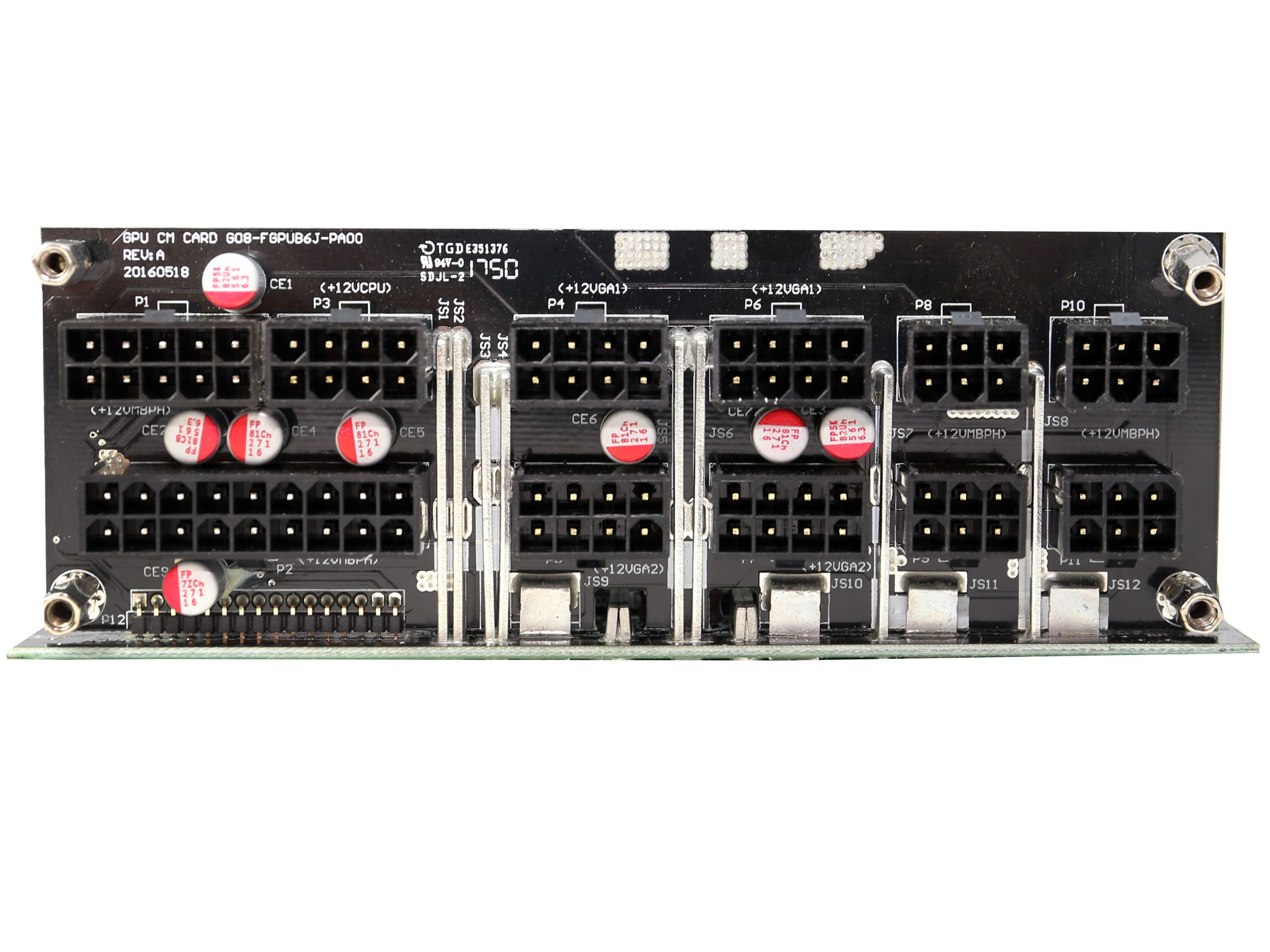
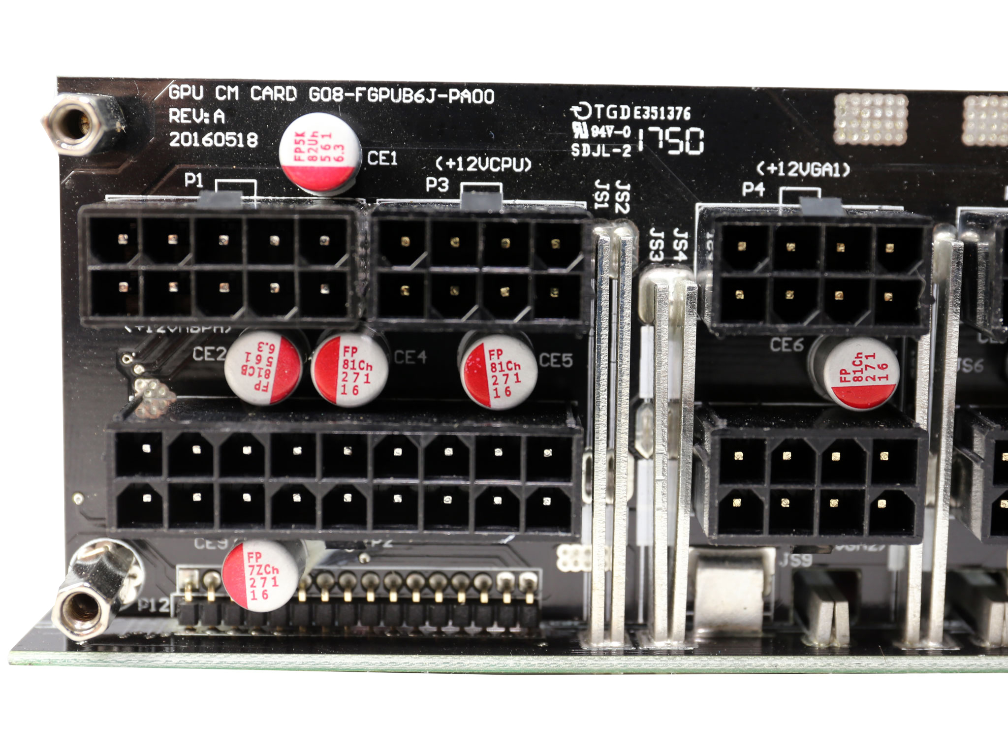
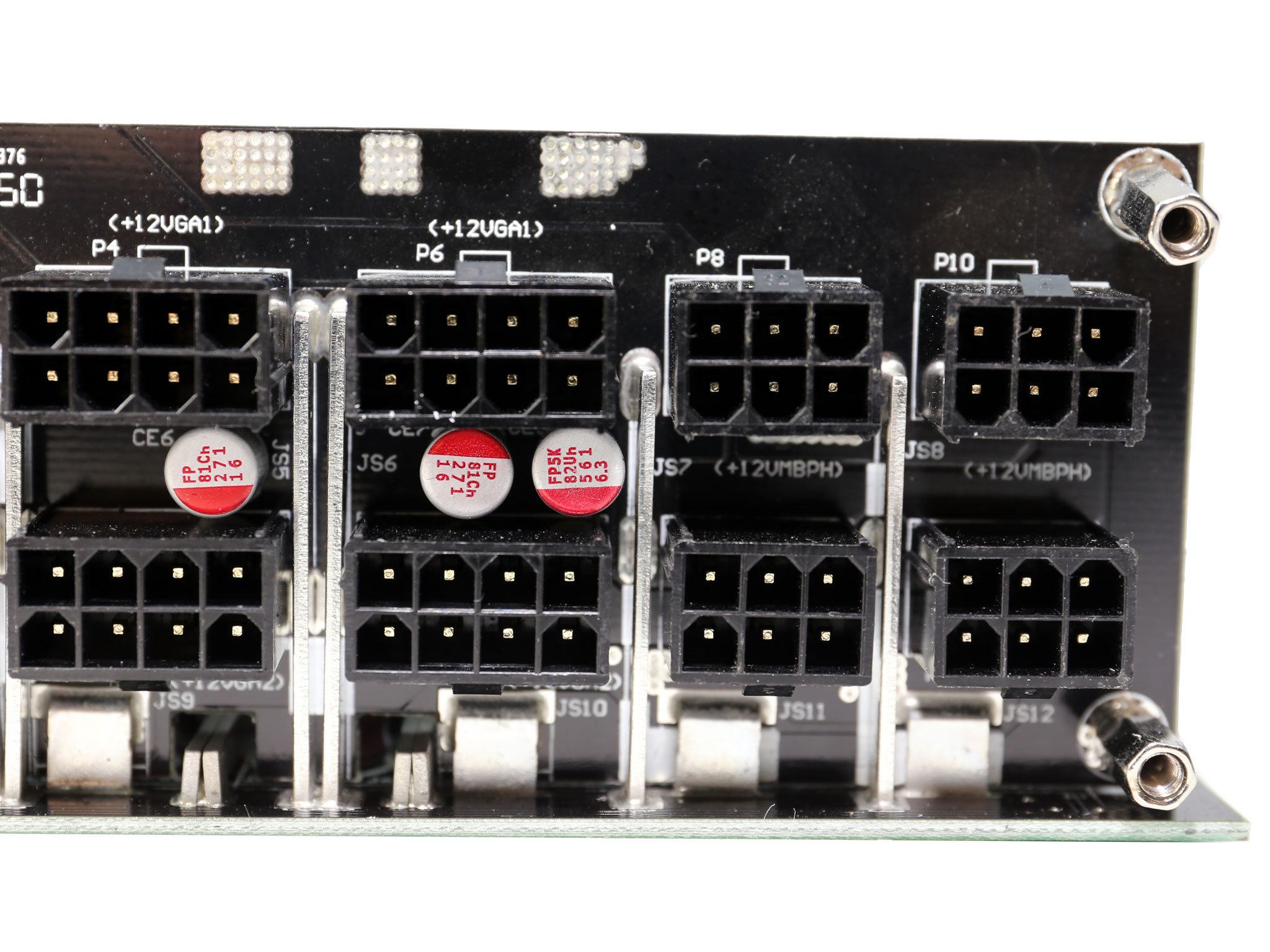
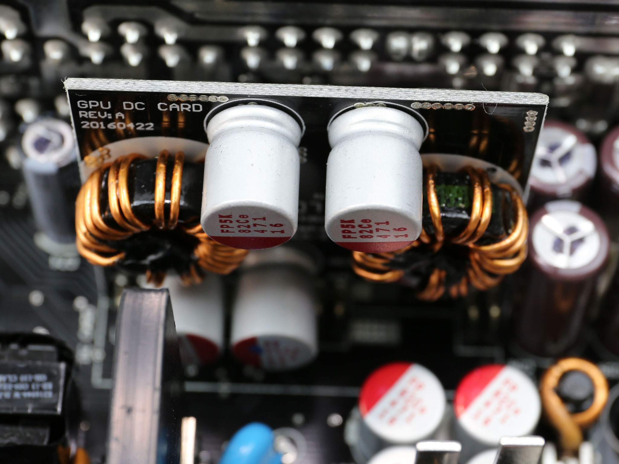
At the front side of the modular PCB lots of polymer caps further suppress ripple. The modular panel is connected to the main board through several bus bars, in order to restrict energy losses.
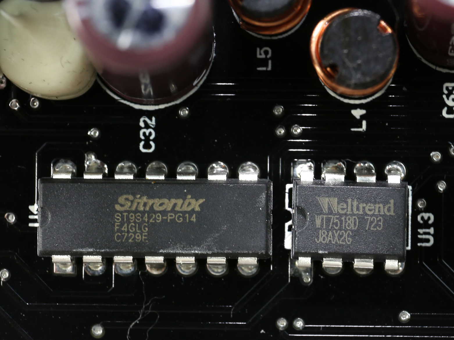
A coupe of protection ICs are used, to offer OCP for up to four +12V rails: a Sytronix ST9S429-PG14 and a Weltrend WD7518D. An LM393G, dual differential comparator is used, to support the protection ICs.
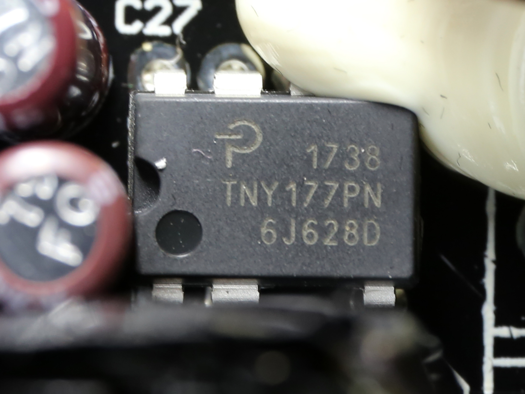
The standby PWM controller, responsible for the 5VSB rail, is a TinySwitch-LT TNY177PN.
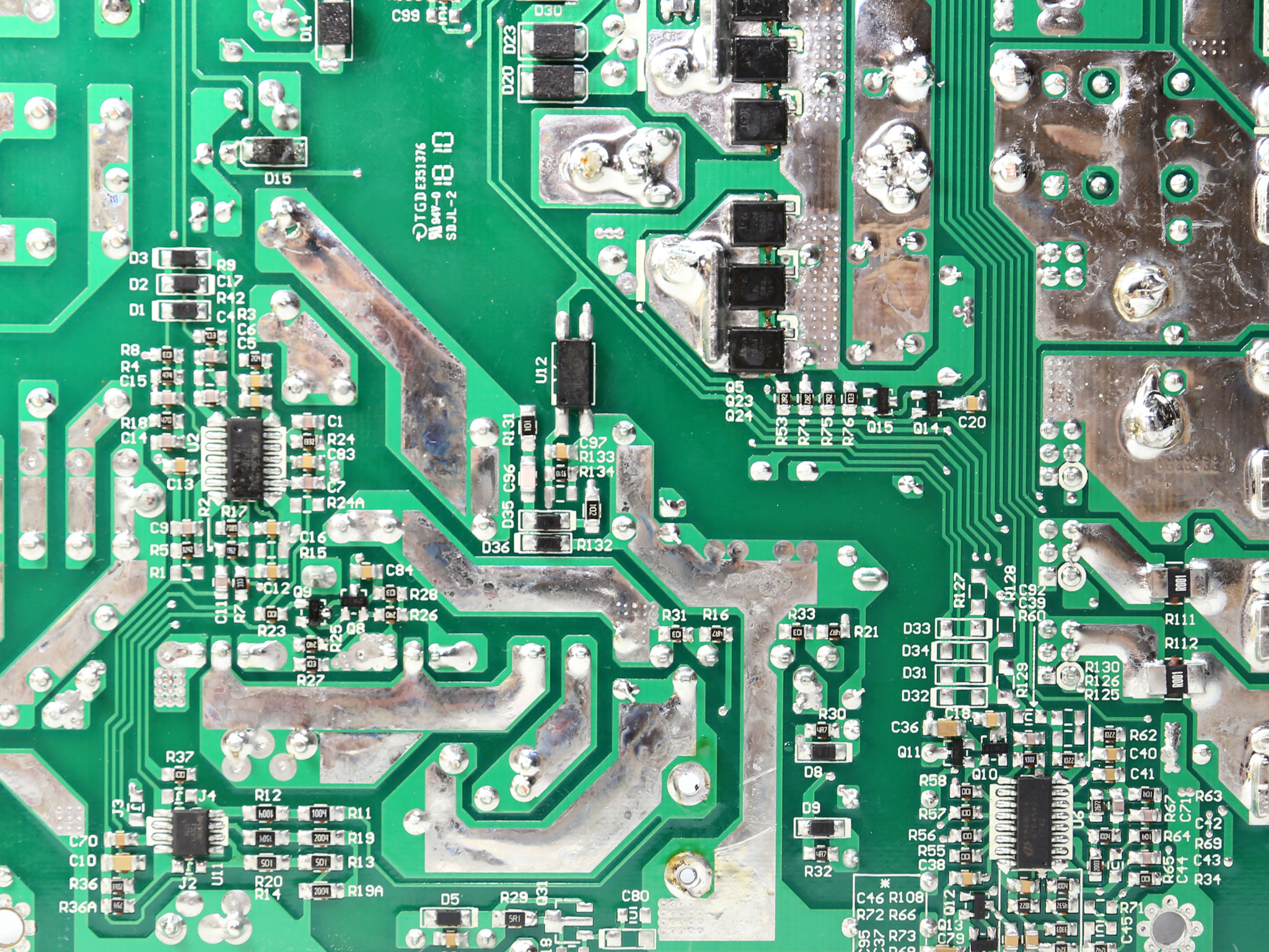
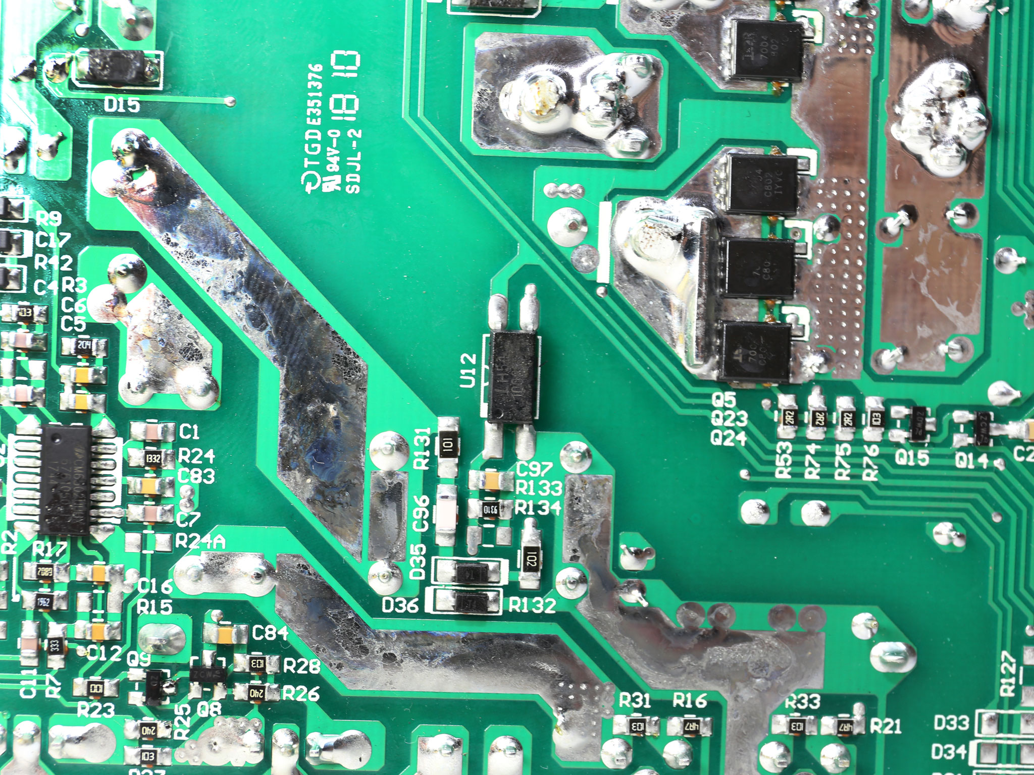
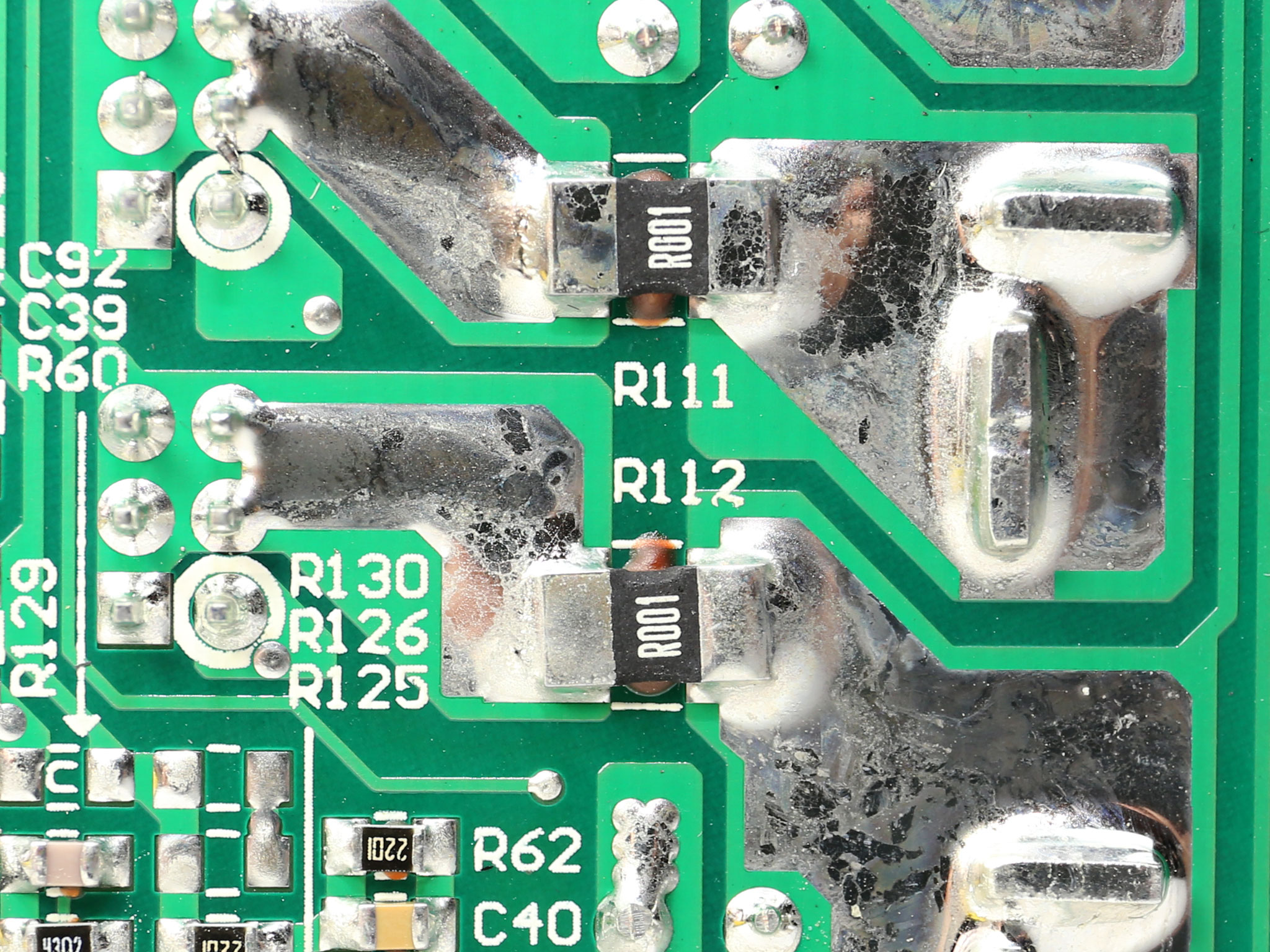
The soldering quality is good. CWT usually doesn't let us down when it comes to this and this unit is no exception.
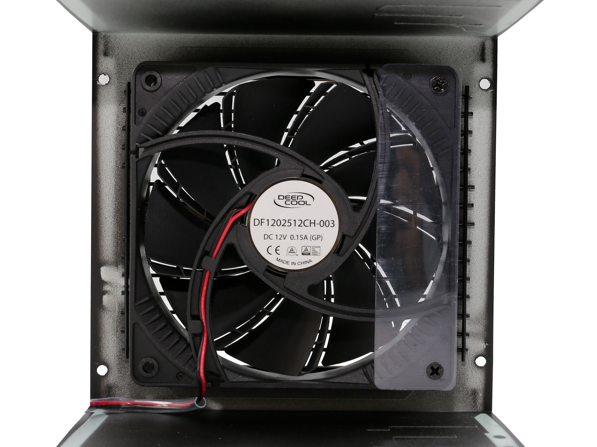
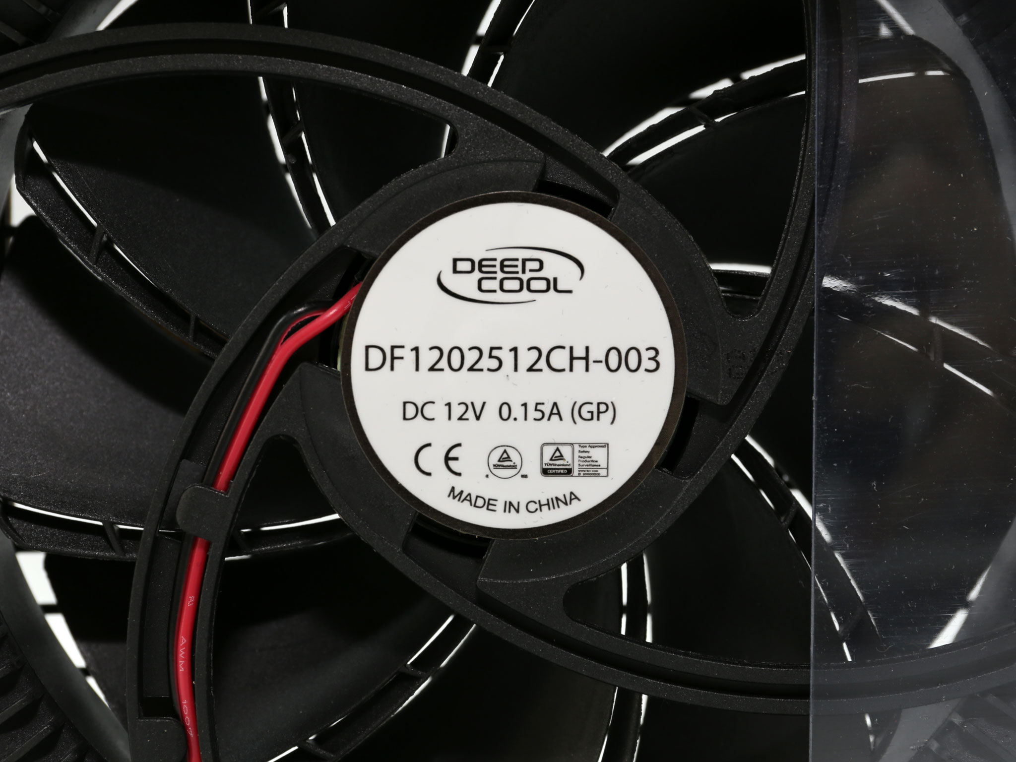
The cooling fan's model number is DF1202512CH-003. It measures 120mm across and it uses a single fluid dynamic bearing, so it will last for quite long.
To learn more about our PSU tests and methodology, please check out How We Test Power Supply Units.
Primary Rails And 5VSB Load Regulation
Load Regulation testing is detailed here.
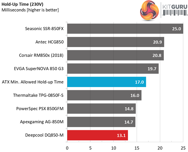
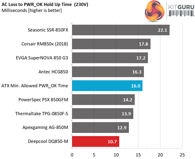
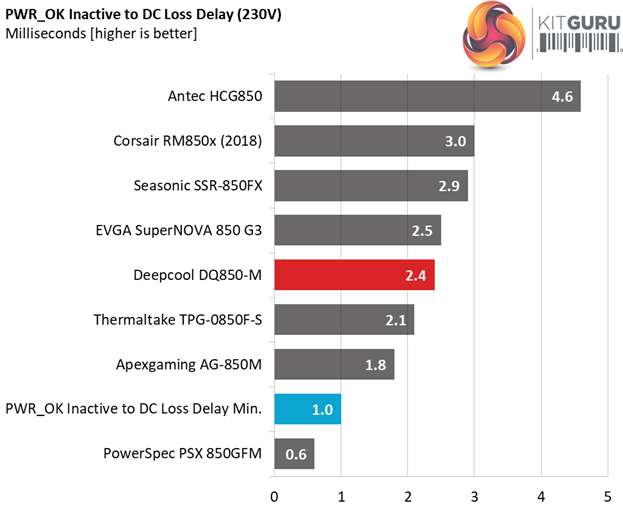
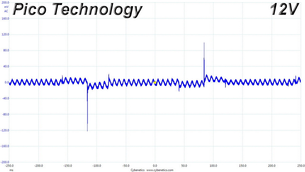
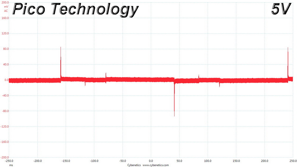
Hold-Up Time
Our hold-up time tests are described in detail here.
The oscilloscope screenshots that we took during the hold-up time measurements:
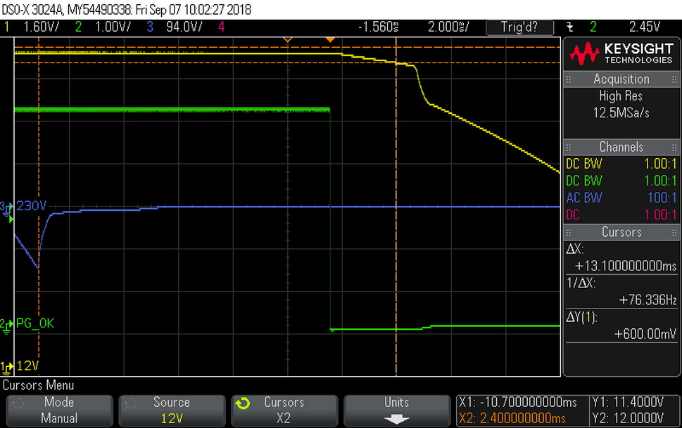
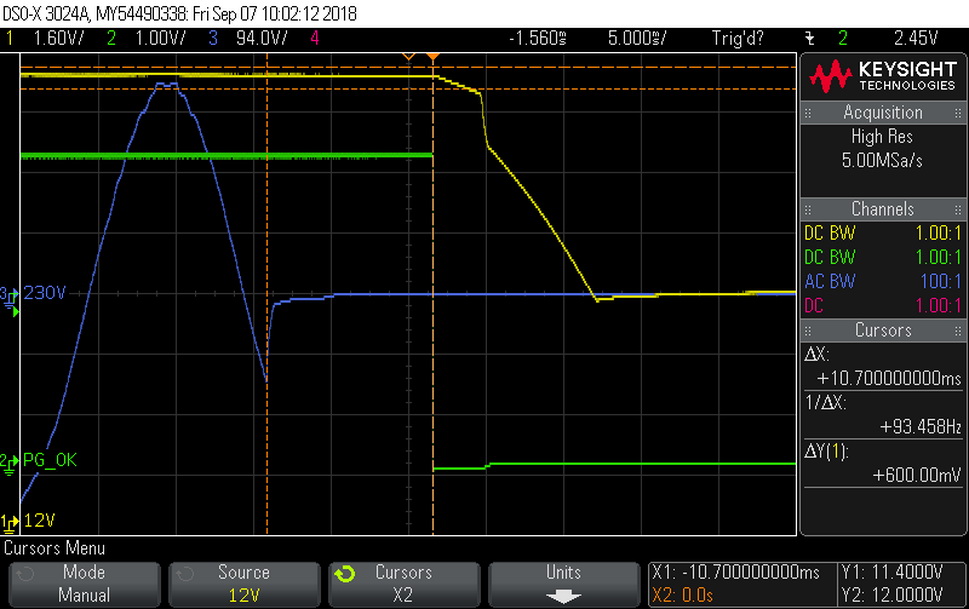

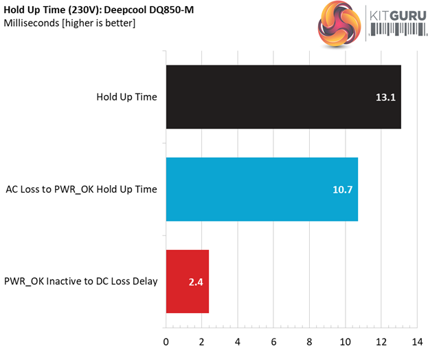
The bulk cap's capacity is not high enough to offer a longer than 17ms hold-up time and this is a great shame. At least the power ok signal is accurate, however it is much lower than 16ms that the ATX spec requires.
Inrush Current
For details on our inrush current testing, please click here.
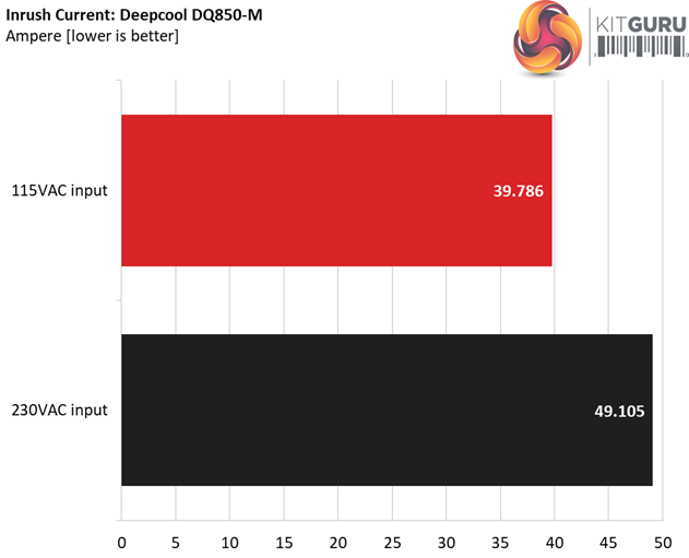
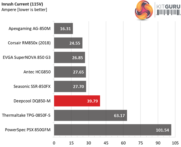
The registered inrush current with both 115V and 230V input is at normal levels for this wattage.
Load Regulation And Efficiency Measurements
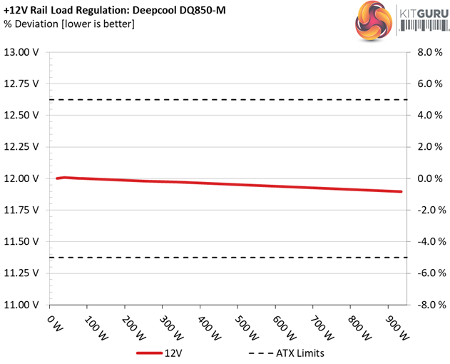
The first set of tests reveals the stability of the voltage rails and the DQ850-M’s efficiency. The applied load equals (approximately) 10 to 110 percent of the power supplies maximum load in increments of 10 percentage points.
We conducted two additional tests.
During the first, we stressed the two minor rails (5V and 3.3V) with a high load, while the load at +12V was only 0.1A. This test reveals whether a power supply is compatible with Intel’s C6/C7 sleep states or not. In the second test, we determined the maximum load the +12V rail could handle with minimal load on the minor rails.
| Test # | 12V | 5V | 3.3V | 5VSB | DC/AC (Watts) | Efficiency | Fan Speed (RPM) | PSU Noise (dB[A]) | Temps (In/Out) | PF/AC Volts |
| 1 | 5.270A | 1.983A | 1.962A | 0.986A | 84.836 | 87.613% | 752 | 18.7 | 40.02°C | 0.966 |
| 12.001V | 5.044V | 3.359V | 5.070V | 96.830 | 43.67°C | 115.12V | ||||
| 2 | 11.546A | 2.976A | 2.946A | 1.185A | 169.339 | 90.793% | 757 | 18.7 | 40.27°C | 0.981 |
| 11.991V | 5.041V | 3.357V | 5.062V | 186.511 | 44.22°C | 115.11V | ||||
| 3 | 18.235A | 3.475A | 3.426A | 1.385A | 254.477 | 91.472% | 760 | 18.8 | 41.21°C | 0.983 |
| 11.981V | 5.038V | 3.355V | 5.056V | 278.201 | 45.47°C | 115.11V | ||||
| 4 | 24.930A | 3.973A | 3.936A | 1.585A | 339.675 | 91.416% | 755 | 18.7 | 41.75°C | 0.981 |
| 11.972V | 5.036V | 3.354V | 5.050V | 371.569 | 46.21°C | 115.11V | ||||
| 5 | 31.310A | 4.968A | 4.923A | 1.785A | 425.005 | 90.910% | 757 | 18.7 | 42.21°C | 0.980 |
| 11.961V | 5.033V | 3.352V | 5.042V | 467.500 | 47.29°C | 115.11V | ||||
| 6 | 37.630A | 5.963A | 5.911A | 1.986A | 509.517 | 89.698% | 757 | 18.7 | 42.77°C | 0.981 |
| 11.951V | 5.031V | 3.350V | 5.035V | 568.039 | 48.24°C | 115.11V | ||||
| 7 | 44.034A | 6.962A | 6.899A | 2.188A | 594.867 | 88.809% | 1200 | 28.2 | 43.83°C | 0.983 |
| 11.940V | 5.028V | 3.348V | 5.027V | 669.828 | 49.66°C | 115.23V | ||||
| 8 | 50.449A | 7.961A | 7.889A | 2.391A | 680.216 | 87.916% | 1655 | 37.1 | 44.34°C | 0.984 |
| 11.929V | 5.026V | 3.346V | 5.019V | 773.708 | 50.45°C | 115.14V | ||||
| 9 | 57.278A | 8.463A | 8.375A | 2.392A | 765.155 | 87.129% | 1743 | 40.9 | 45.20°C | 0.986 |
| 11.918V | 5.023V | 3.344V | 5.017V | 878.183 | 51.82°C | 115.29V | ||||
| 10 | 64.052A | 8.965A | 8.885A | 2.495A | 849.876 | 86.254% | 1743 | 40.9 | 45.38°C | 0.987 |
| 11.907V | 5.021V | 3.342V | 5.011V | 985.319 | 52.78°C | 115.15V | ||||
| 11 | 71.227A | 8.970A | 8.891A | 2.496A | 934.678 | 85.234% | 1743 | 40.9 | 46.58°C | 0.988 |
| 11.898V | 5.018V | 3.341V | 5.009V | 1096.597 | 54.30°C | 115.14V | ||||
| CL1 | 0.148A | 14.001A | 14.001A | 0.000A | 119.102 | 83.836% | 777 | 19.1 | 42.71°C | 0.977 |
| 11.986V | 5.034V | 3.346V | 5.080V | 142.065 | 47.83°C | 115.13V | ||||
| CL2 | 70.836A | 1.002A | 1.000A | 1.000A | 857.727 | 86.944% | 1750 | 40.9 | 45.30°C | 0.987 |
| 11.919V | 5.022V | 3.351V | 5.049V | 986.525 | 52.41°C | 115.21V |
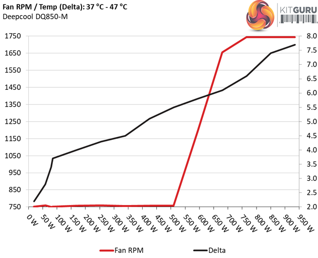
There is no passive operation at light loads, however the fan profile is quite relaxed. It needs 80% of the unit's max rated load and over 44°C to push the fan high speeds and even in the worst case scenario the PSU's noise is at 41 dB(A).
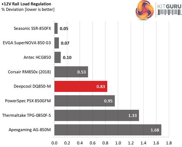
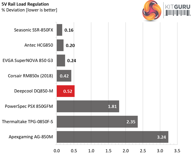
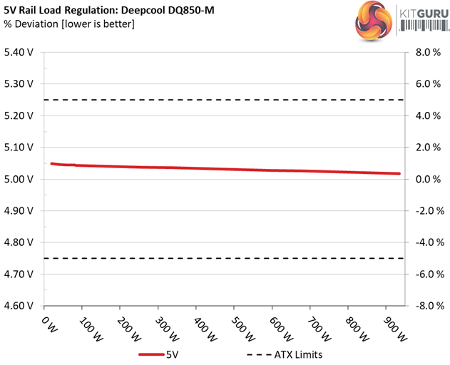
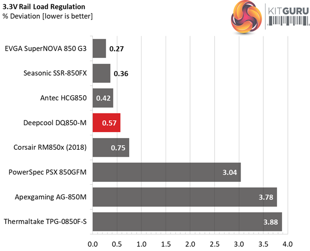
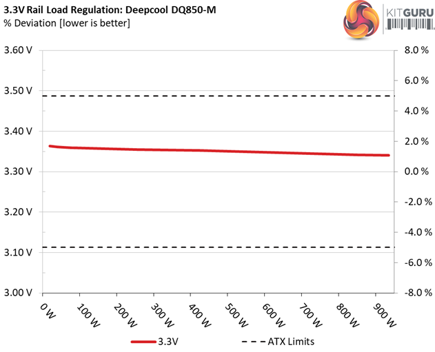
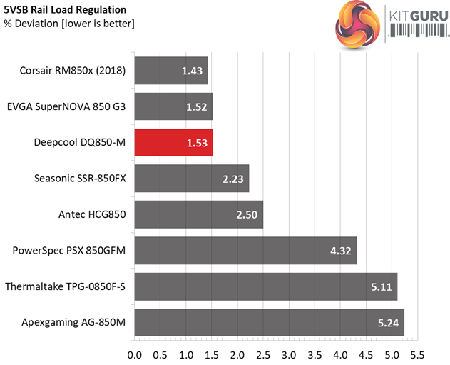
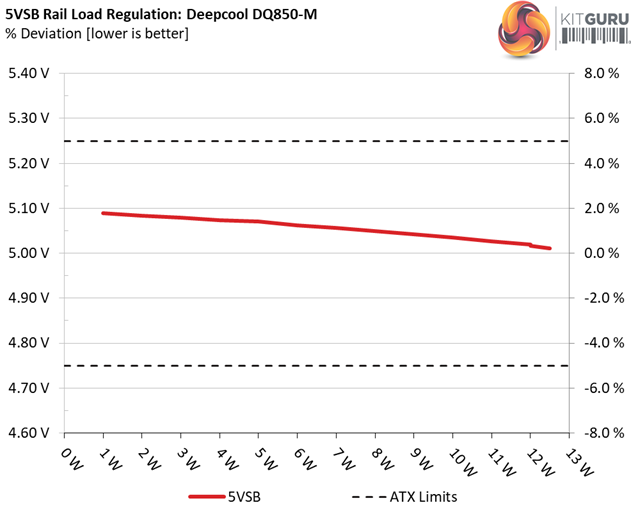
The load regulation at +12V is tight enough, however it cannot compete against the performance of Seasonic's Focus platform. On the 5V and 3.3V rails the deviations are low as well and at 5VSB the load regulation is among the best in this category.
This platform easily meets the 80 PLUS Gold requirements with 20% and 50% load, even under high operating temperatures. It falls short with full load, however we apply almost 23°C more than what the 80 PLUS uses for its evaluations, and the higher the operating temperature the more the impact on a PSU's efficiency.
Efficiency
Our efficiency testing procedure is detailed here.
Using results from the previous page, we plotted a chart showing the DQ850-M’s efficiency at low loads, and loads from 10 to 110 percent of its maximum-rated capacity.

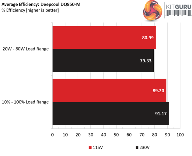
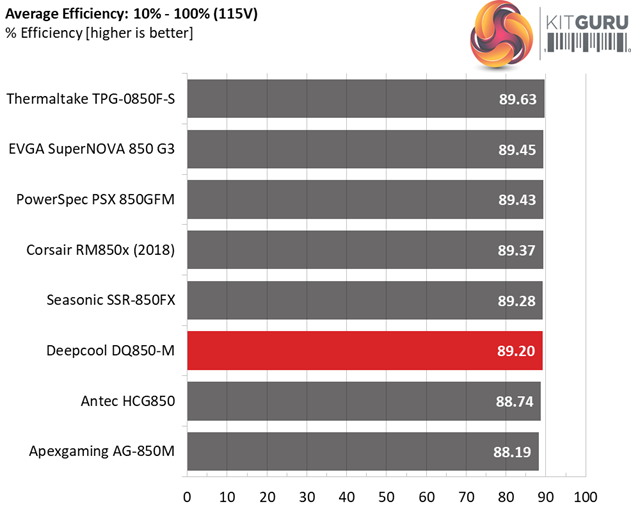
Under normal loads the DQ850-M is close to the competition and with light loads it performs better than the majority of its opponents, losing only to the Leadex II platform of the EVGA 850 G3 model.
Efficiency At Low Loads
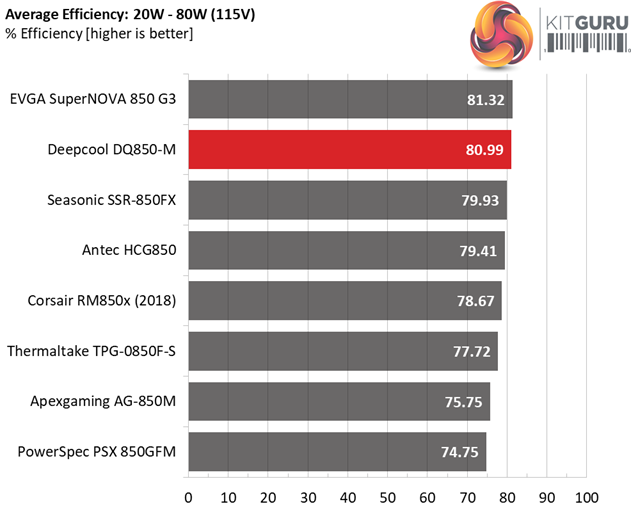
In the following tests, we measure the DQ850-M's efficiency at loads significantly lower than 10 percent of its maximum capacity (the lowest load the 80 PLUS standard measures). The loads we dial are 20, 40, 60, and 80W. This is important for representing when a PC is idle, with power-saving features turned on.
| Test # | 12V | 5V | 3.3V | 5VSB | DC/AC (Watts) | Efficiency | Fan Speed (RPM) | PSU Noise (dB[A]) | PF/AC Volts |
| 1 | 1.206A | 0.497A | 0.476A | 0.197A | 19.586 | 70.005% | 752 | 18.7 | 0.822 |
| 12.001V | 5.049V | 3.363V | 5.089V | 27.978 | 115.13V | ||||
| 2 | 2.468A | 0.991A | 0.980A | 0.394A | 39.933 | 81.419% | 755 | 18.7 | 0.918 |
| 12.007V | 5.047V | 3.361V | 5.084V | 49.046 | 115.12V | ||||
| 3 | 3.669A | 1.487A | 1.458A | 5.079A | 59.449 | 85.138% | 760 | 18.8 | 0.948 |
| 12.005V | 5.045V | 3.360V | 5.079V | 69.827 | 115.11V | ||||
| 4 | 4.937A | 1.982A | 1.963A | 0.788A | 79.845 | 87.400% | 750 | 18.7 | 0.965 |
| 12.002V | 5.045V | 3.359V | 5.074V | 91.356 | 115.11V |
The efficiency is kept high even under light loads, while the lack of a passive mode doesn't bother us, at all, since the cooling fan's speed and noise are kept low.
5VSB Efficiency
The ATX specification (revision 1.4), along with CEC, ErP Lot 3 2014 and ErP Lot 6 2010/2013, states that the 5VSB standby supply efficiency should be as high as possible, recommending 75 percent or higher with 550mA, 1A, and 1.5A of load.
The supply should also achieve higher than 75% efficiency at 5VSB under full load, or with 3A if its max current output on this rail is higher than 3A.
We take six measurements: one each at 100, 250, 550, 1000, and 1500mA, and one with the full load the 5VSB rail can handle.
| Test # | 5VSB | DC/AC (Watts) |
Efficiency | PF/AC Volts |
| 1 | 0.100A | 0.509 | 76.198% | 0.067 |
| 5.091V | 0.668 | 115.12V | ||
| 2 | 0.250A | 1.272 | 79.252% | 0.150 |
| 5.088V | 1.605 | 115.12V | ||
| 3 | 0.550A | 2.796 | 80.046% | 0.267 |
| 5.082V | 3.493 | 115.12V | ||
| 4 | 1.000A | 5.074 | 77.978% | 0.365 |
| 5.073V | 6.507 | 115.12V | ||
| 5 | 1.500A | 7.596 | 77.844% | 0.418 |
| 5.063V | 9.758 | 115.12V | ||
| 6 | 2.500A | 12.610 | 75.270% | 0.466 |
| 5.043V | 16.753 | 115.11V |
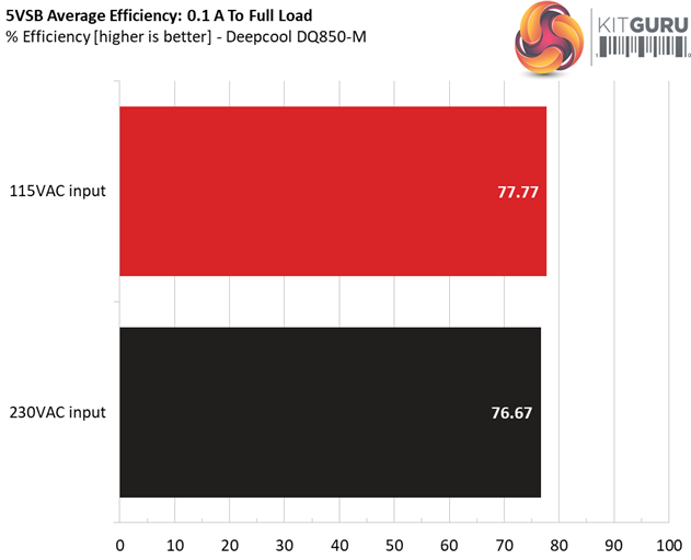
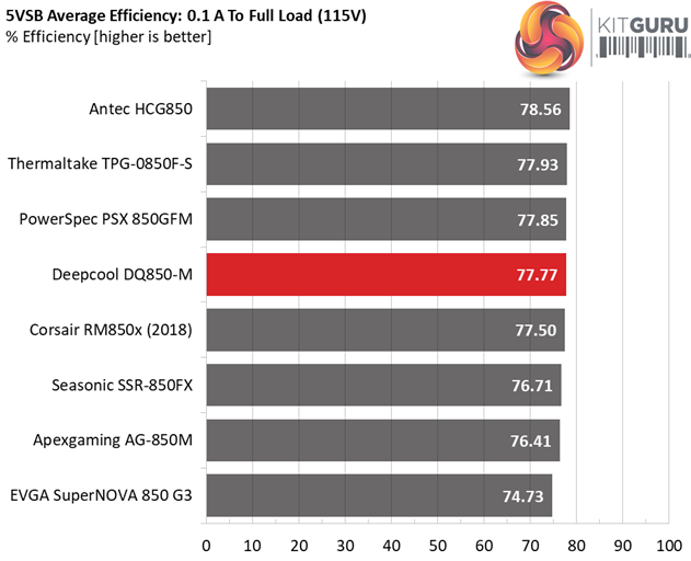
Typically for a high-end CWT platform, the 5VSB rail's efficiency is at good levels.
Power Consumption In Idle And Standby
In the table below, you’ll find the power consumption and voltage values of all rails (except -12V) when the PSU is idle (powered on, but without any load on its rails), and the power consumption when the unit is in standby mode (without any load, at 5VSB).
| Mode | 12V | 5V | 3.3V | 5VSB | Watts | PF/AC Volts |
| Idle | 12.001V | 5.052V | 3.362V | 5.094V | 5.809 | 0.355 |
| 115.1V | ||||||
| Standby | 0.049 | 0.005 | ||||
| 115.1V | ||||||
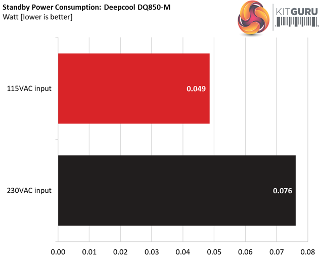
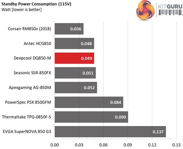
The power needs of this platform at standby are very low, regardless of the input voltage.
Fan RPM, Delta Temperature, And Output Noise
Our mixed noise testing is described in detail here.
The first chart below illustrates the cooling fan's speed (in RPM), and the delta between input and output temperature. The results were obtained at 37°C (98.6°F) to 47°C (116.6°F) ambient temperature.
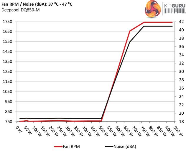
The next chart shows the cooling fan's speed (again, in RPM) and output noise. We measure acoustics from one meter away, inside a hemi-anechoic chamber. Background noise inside the chamber is below 6 dB(A) during testing (it's actually much lower, but our sound meter’s microphone hits its floor), and the results are obtained with the PSU operating at 37°C (98.6°F) to 47°C (116.6°F) ambient temperature.
 The following graph illustrates the fan's output noise over the PSU's operating range. The same conditions of the above graph apply to our measurements, though the ambient temperature is between 30°C (86°F) to 32°C (89.6°F).
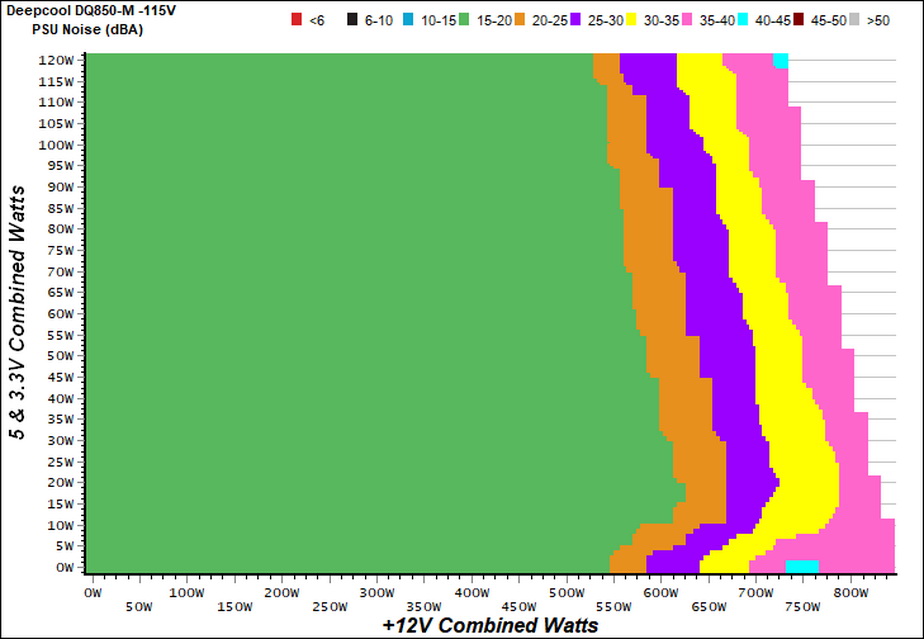
There is no passive operation but as you can see in the graph above, up to 550W (at +12V) the PSU's noise is kept very low, within the 15-20 dB(A) range. It needs about 90W more to exceed 30 dB(A) and with 695W and more it enters the 35-40 dB(A) zone. With a larger diameter fan the noise output could be even lower.
Protection Features
Our protection features evaluation methodology is described in detail here.
|
Protection |
|
|
OCP |
12V1 (MBPH): 34.45A (137.8%),11.78V |
|
OPP |
1254.1W (147.54%) |
|
OTP |
✓ (125°C @ 12V Heatsink) |
|
SCP |
12V: ✓ |
|
PWR_OK |
Proper Operation (but lower than 16ms) |
|
NLO |
✓ |
|
SIP |
Surge: MOV |
The over current protection on the +12V rails is properly set, and the same applies to the rest rails as well. On the other hand, the over power protection is way higher than 130% which is a safe level.
The over temperature protection is present and working, while there is short circuit protection on all rails. Finally, the power ok signal is accurate, but it is much lower than 16ms that the ATX spec requires).
DC Power Sequencing
According to Intel’s most recent Power Supply Design Guide (revision 1.4) the +12V and 5V voltages must be equal or greater than the 3.3V rail’s output at all times, during the power-up and normal operation. For our first measurement, we turn the unit off and switch it back on without any load in any of the rails.
In the second test, we set the PSU to standby mode, dial full load and start it afterwards. In the last test, while the power supply is completely switched off (we cut off the power or switch the supply off through its power switch), we dial full load before restoring power.
The results are almost perfect. The 3.3V is kept lower than 12V and 5V at all times and the registered peaks are within 20ms.
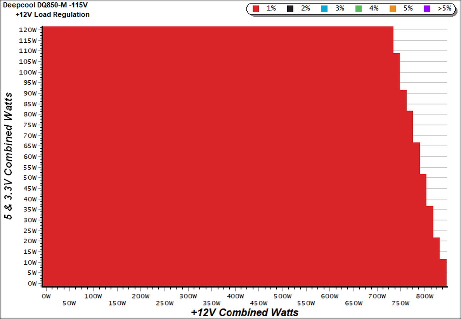
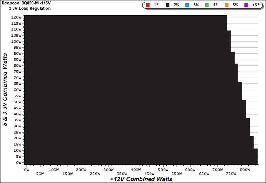
Our cross-load tests are described in detail here.
To generate the following charts, we set our loaders to auto mode through our custom-made software before trying more than 1500 possible load combinations with the +12V, 5V, and 3.3V rails. The load regulation deviations in each of the charts below are calculated by taking the nominal values of the rails (12V, 5V, and 3.3V) as point zero. The ambient temperature is between at 30°C (86°F) to 32°C (89.6°F).
Load Regulation Charts

Efficiency Chart
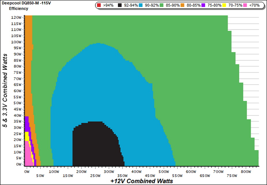
For a quite large region the unit's efficiency is above 92%. From 100W to 540W at +12V and with the load on the minor rails remaining lower than 100W, the efficiency levels are within 90-92%.
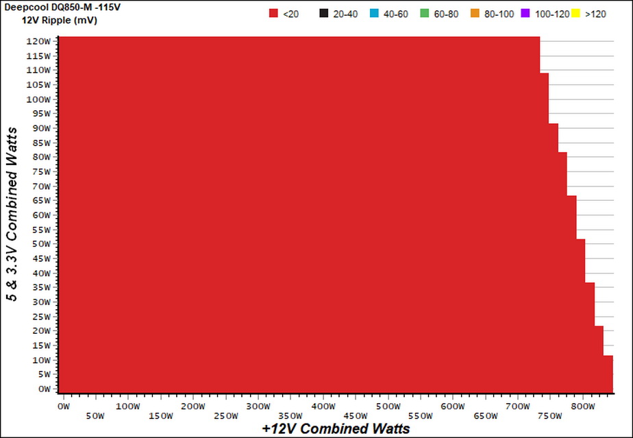
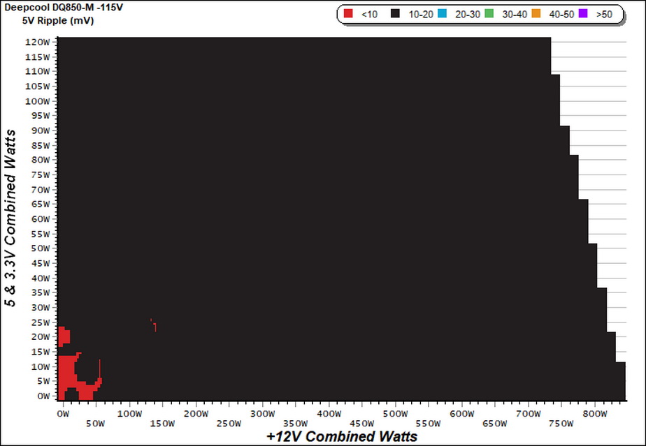
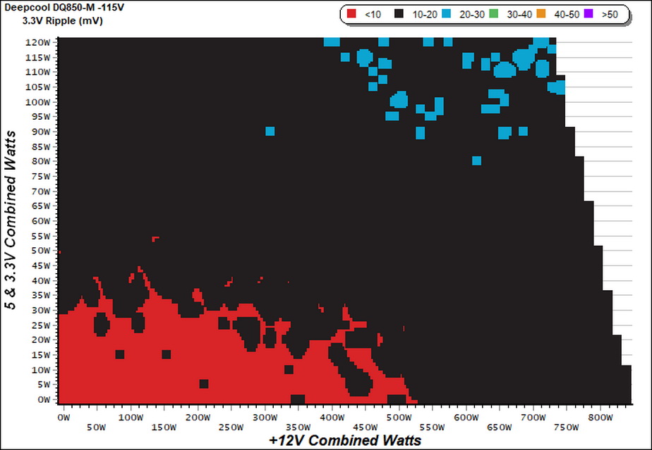
Ripple Charts

Infrared Images
We apply half-load for 10 minutes with the PSU’s top cover and cooling fan removed before taking photos with our modified FLIR E4 camera that delivers 320×240 IR resolution (76,800 pixels).
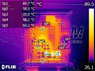
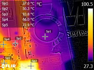
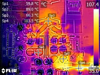
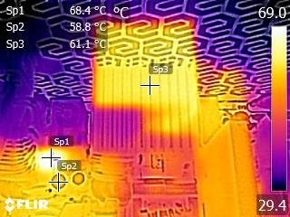
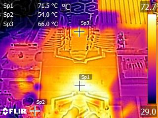
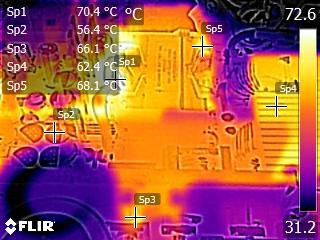
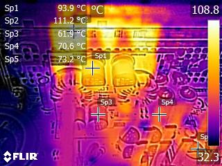
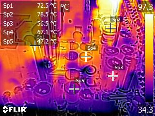
The temperatures on the VRMs are increased, because we pushed those rails hard during the ten-minute load period. A pair of polymer caps located close to the VRMs has increased operating temperature as well at 89°C.
Thankfully those caps are highly tolerant to increased temperatures, contrary to electrolytic ones. The four electrolytic caps close to the VRMs and the modular board operate at over 70°C, which is not a low temperature. On the contrary, the bulk cap has a very low temperature of 37°C. Given the information that we gathered during this session, we believe that the fan profile is properly set and maybe it should be a bit more aggressive at typical and higher loads.
Advanced Transient Response Tests
For details on our transient response testing, please click here.
These tests are crucial because they simulate the transient loads a PSU is likely to handle (such as booting a RAID array or an instant 100 percent load of CPU/GPUs). We call these “Advanced Transient Response Tests” and they are designed to be very tough to master, especially for a PSU with a capacity of less than 500W.
In all of the tests, we use an oscilloscope to measure the voltage drops caused by the transient load. The voltages should remain within the ATX specifications regulation limits.
We should note that the ATX spec requires for capacitive loading during the transient rests, but in our methodology we chose to apply the worst case scenario with no extra capacitance on the rails.
Advanced Transient Response at 20 Percent – 200ms
| Voltage | Before | After | Change | Pass/Fail |
|---|---|---|---|---|
| 12V | 11.991V | 11.871V | 1.00% | Pass |
| 5V | 5.040V | 4.952V | 1.75% | Pass |
| 3.3V | 3.357V | 3.202V | 4.62% | Pass |
| 5VSB | 5.061V | 5.005V | 1.11% | Pass |
Advanced Transient Response at 20 Percent – 20ms
| Voltage | Before | After | Change | Pass/Fail |
|---|---|---|---|---|
| 12V | 11.990V | 11.801V | 1.58% | Pass |
| 5V | 5.040V | 4.933V | 2.12% | Pass |
| 3.3V | 3.356V | 3.167V | 5.63% | Pass |
| 5VSB | 5.061V | 4.995V | 1.30% | Pass |
Advanced Transient Response at 20 Percent – 1ms
| Voltage | Before | After | Change | Pass/Fail |
|---|---|---|---|---|
| 12V | 11.989V | 11.785V | 1.70% | Pass |
| 5V | 5.041V | 4.928V | 2.24% | Pass |
| 3.3V | 3.356V | 3.171V | 5.51% | Pass |
| 5VSB | 5.061V | 5.009V | 1.03% | Pass |
Advanced Transient Response at 50 Percent – 200ms
| Voltage | Before | After | Change | Pass/Fail |
|---|---|---|---|---|
| 12V | 11.959V | 11.836V | 1.03% | Pass |
| 5V | 5.034V | 4.943V | 1.81% | Pass |
| 3.3V | 3.351V | 3.189V | 4.83% | Pass |
| 5VSB | 5.041V | 4.985V | 1.11% | Pass |
Advanced Transient Response at 50 Percent – 20ms
| Voltage | Before | After | Change | Pass/Fail |
|---|---|---|---|---|
| 12V | 11.958V | 11.794V | 1.37% | Pass |
| 5V | 5.034V | 4.925V | 2.17% | Pass |
| 3.3V | 3.351V | 3.159V | 5.73% | Pass |
| 5VSB | 5.041V | 4.974V | 1.33% | Pass |
Advanced Transient Response at 50 Percent – 1ms
| Voltage | Before | After | Change | Pass/Fail |
|---|---|---|---|---|
| 12V | 11.958V | 11.781V | 1.48% | Pass |
| 5V | 5.034V | 4.925V | 2.17% | Pass |
| 3.3V | 3.351V | 3.158V | 5.76% | Pass |
| 5VSB | 5.041V | 4.982V | 1.17% | Pass |
Apparently more capacity is required on the +12V rail, for lower voltage drops with transient loads. The transient response at 5V and 5VSB is good however at 3.3V it needs improvement.
Here are the oscilloscope screenshots we took during Advanced Transient Response Testing:
Transient Response At 20 Percent Load – 200ms
Transient Response At 20 Percent Load – 20ms
Transient Response At 20 Percent Load – 1ms
Transient Response At 50 Percent Load – 200ms
Transient Response At 50 Percent Load – 20ms
Transient Response At 50 Percent Load – 1ms
Turn-On Transient Tests
In the next set of tests, we measure the DQ850-M’s response in simpler transient load scenarios—during its power-on phase.
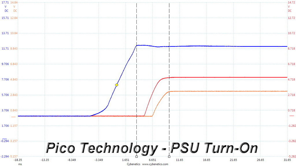
For our first measurement, we turn the DQ850-M off, dial in the maximum current the 5VSB rail can handle, and switch the PSU back on.
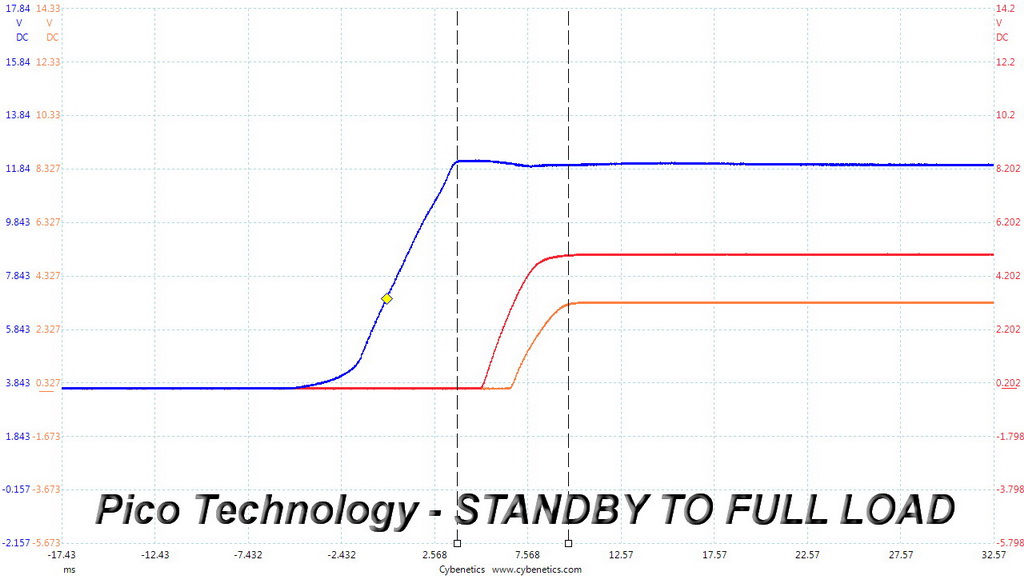
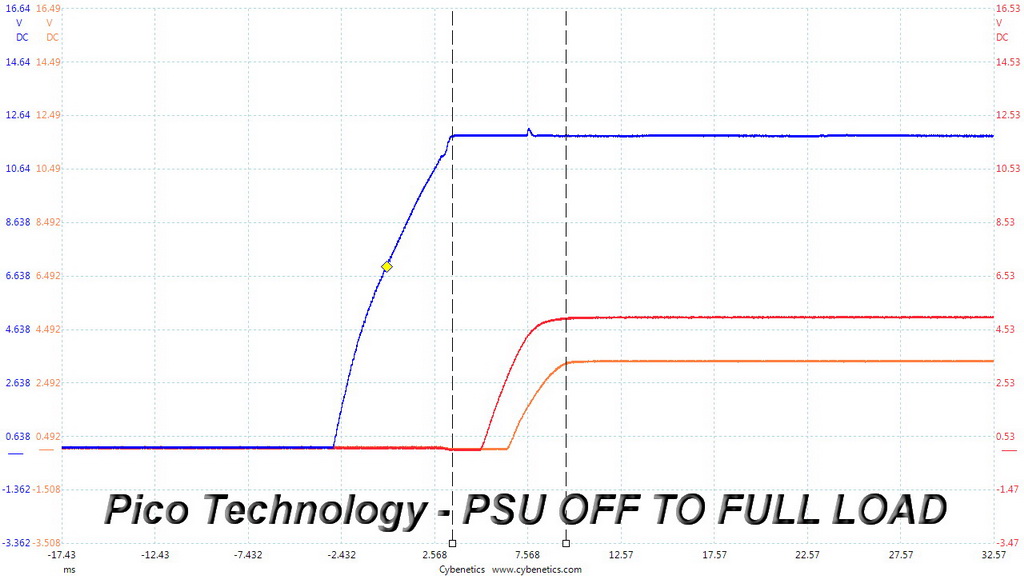
In the second test, we dial the maximum load the +12V rail can handle and start the PSU while it is in standby mode. In the last test, while the PSU is completely switched off (we cut off the power or switch the PSU off through its power switch), we dial the maximum load the +12V rail can handle before restoring power. The ATX specification states that recorded spikes on all rails should not exceed 10 percent of their nominal values (+10 percent for 12V is 13.2V, and 5.5V for 5V).
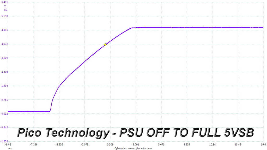
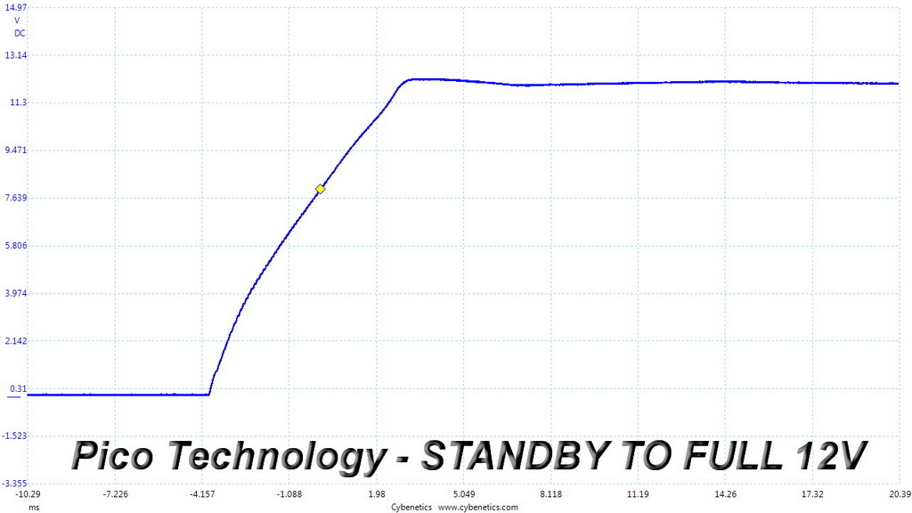
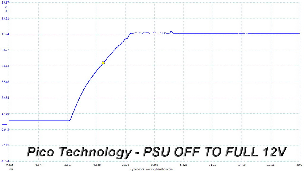
The unit's turn-on response is excellent with no notable voltage overshoots and spikes while all slopes ramp-up smoothly.
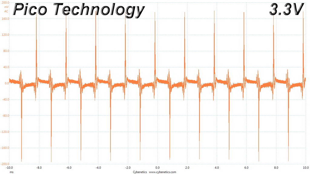
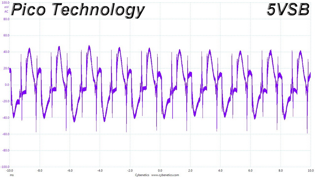
To learn how we measure ripple, please click here.
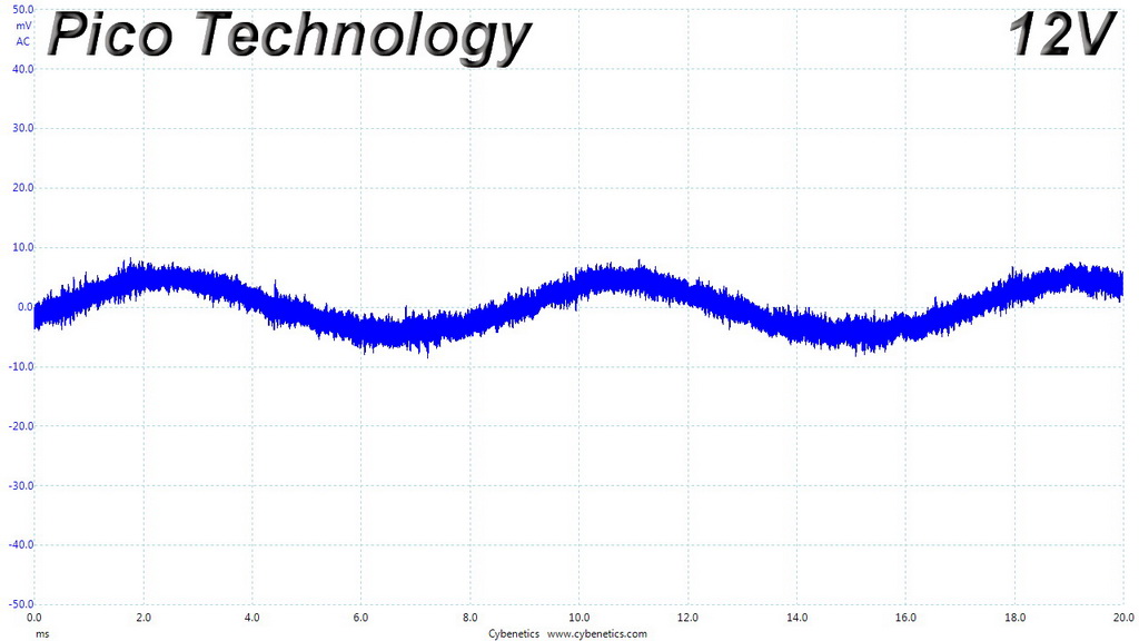
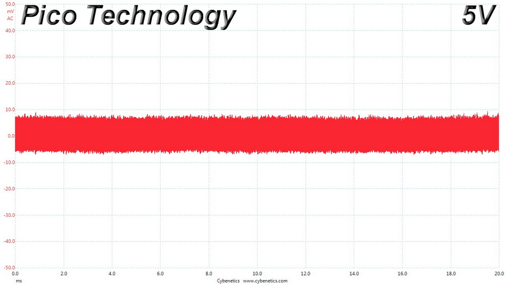
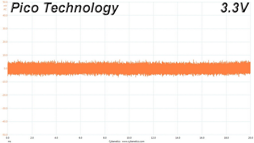
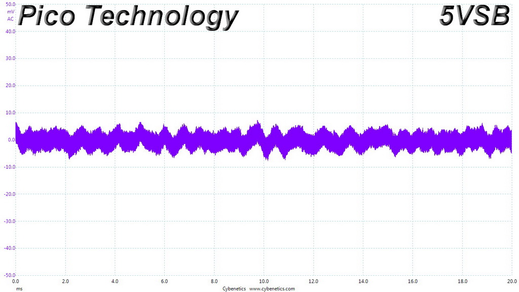
The following table includes the ripple levels we measured on the DQ850-M’s rails. The limits, according to the ATX specification, are 120mV (+12V) and 50mV (5V, 3.3V, and 5VSB).
| Test | 12V | 5V | 3.3V | 5VSB | Pass/Fail |
| 10% Load | 9.6 mV | 12.4 mV | 11.4 mV | 7.4 mV | Pass |
| 20% Load | 12.6 mV | 13.3 mV | 13.0 mV | 8.4 mV | Pass |
| 30% Load | 11.7 mV | 13.8 mV | 13.0 mV | 9.5 mV | Pass |
| 40% Load | 13.0 mV | 13.6 mV | 13.8 mV | 10.3 mV | Pass |
| 50% Load | 13.0 mV | 14.6 mV | 15.0 mV | 11.5 mV | Pass |
| 60% Load | 11.9 mV | 15.1 mV | 15.7 mV | 13.2 mV | Pass |
| 70% Load | 11.4 mV | 17.3 mV | 17.5 mV | 19.1 mV | Pass |
| 80% Load | 12.4 mV | 17.6 mV | 19.6 mV | 21.4 mV | Pass |
| 90% Load | 12.4 mV | 17.4 mV | 20.8 mV | 18.4 mV | Pass |
| 100% Load | 19.9 mV | 18.2 mV | 21.9 mV | 22.5 mV | Pass |
| 110% Load | 19.3 mV | 18.7 mV | 22.5 mV | 25.0 mV | Pass |
| Crossload 1 | 17.4 mV | 14.6 mV | 21.3 mV | 6.5 mV | Pass |
| Crossload 2 | 18.3 mV | 17.5 mV | 16.3 mV | 17.0 mV | Pass |
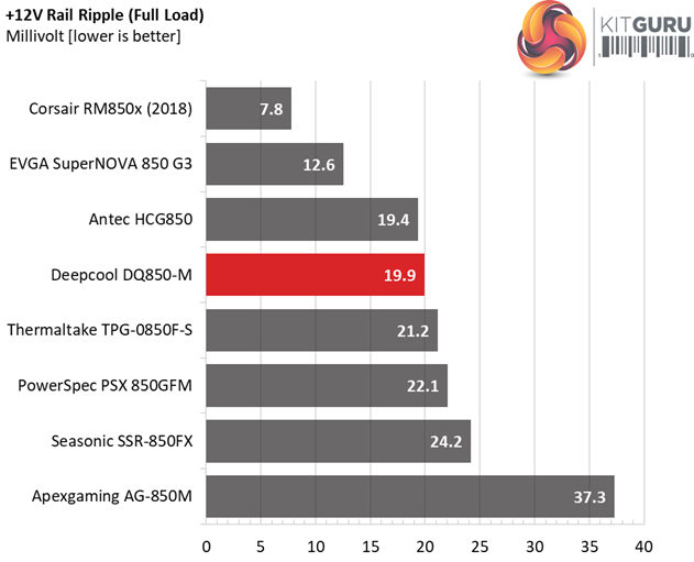
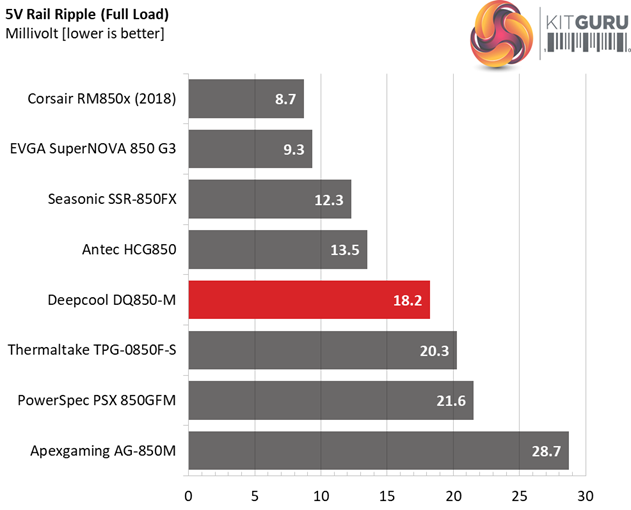
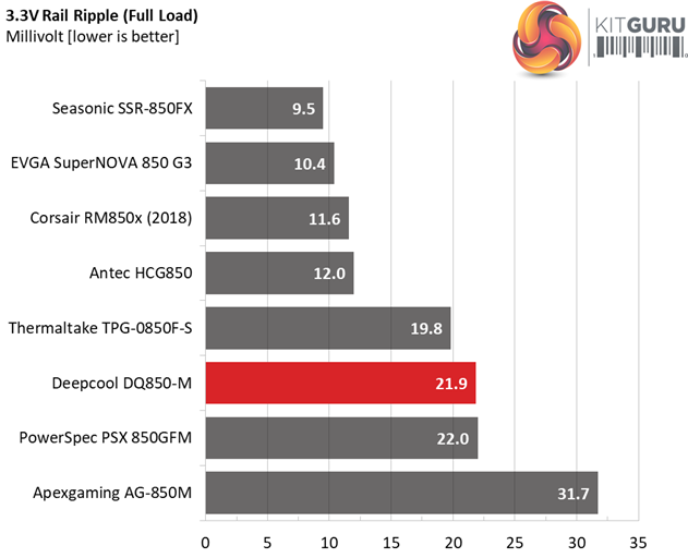
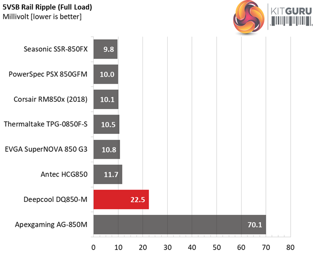
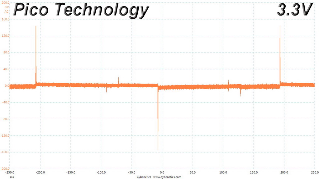
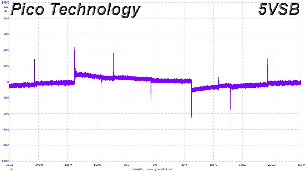
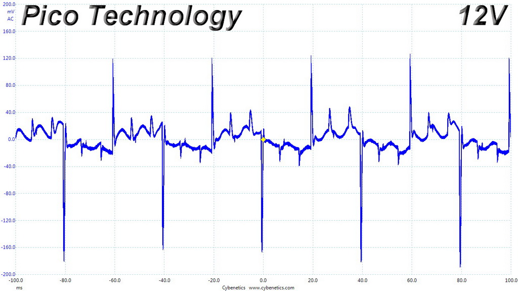
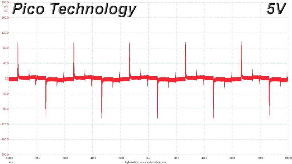
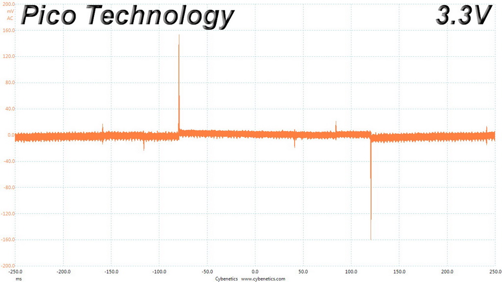
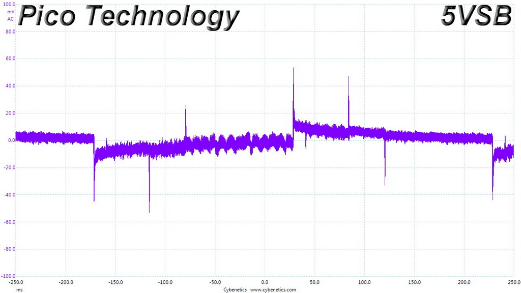
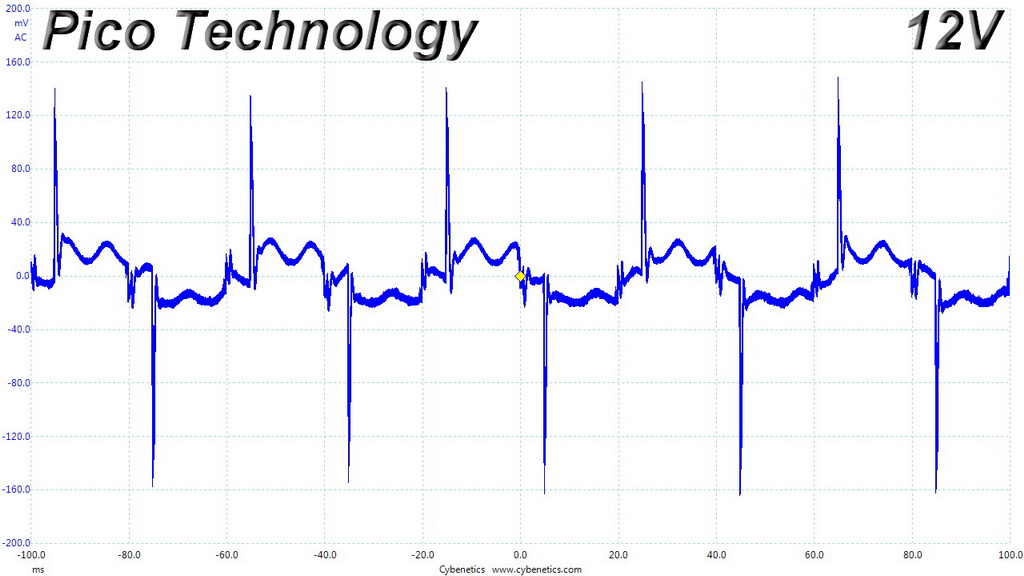
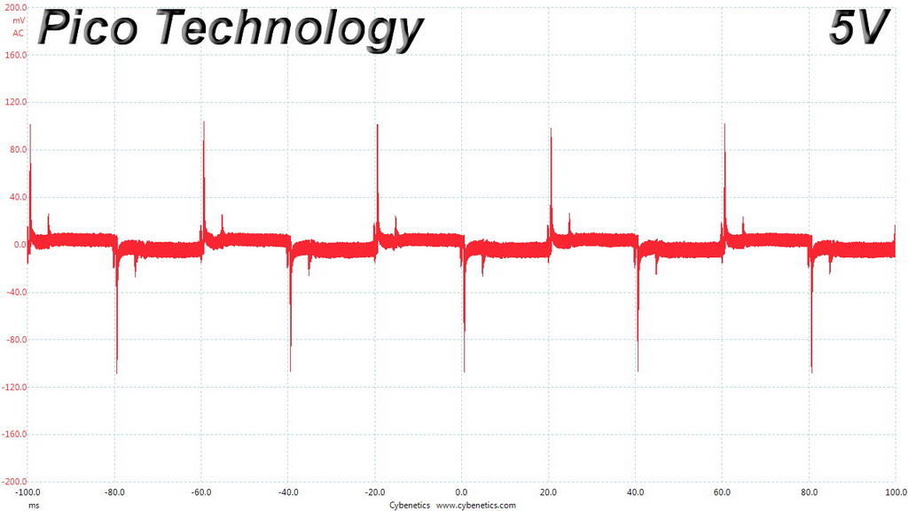
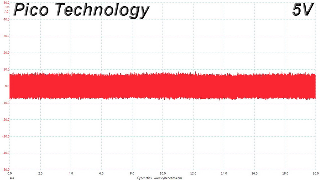
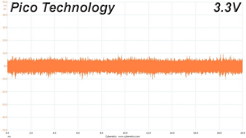
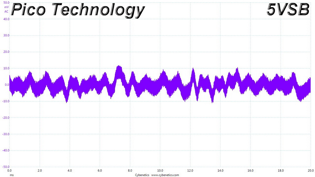
The ripple suppression is good overall, despite the lack of extra filtering caps on the modular cables.
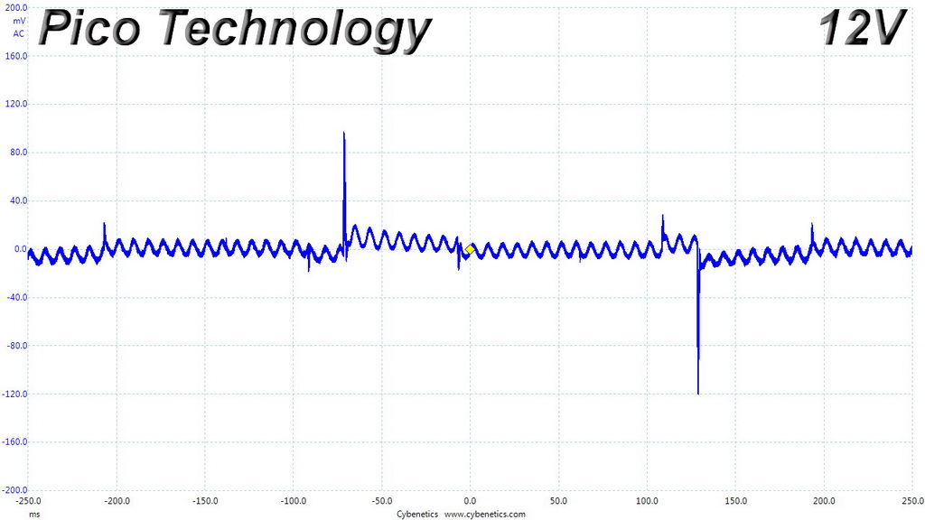
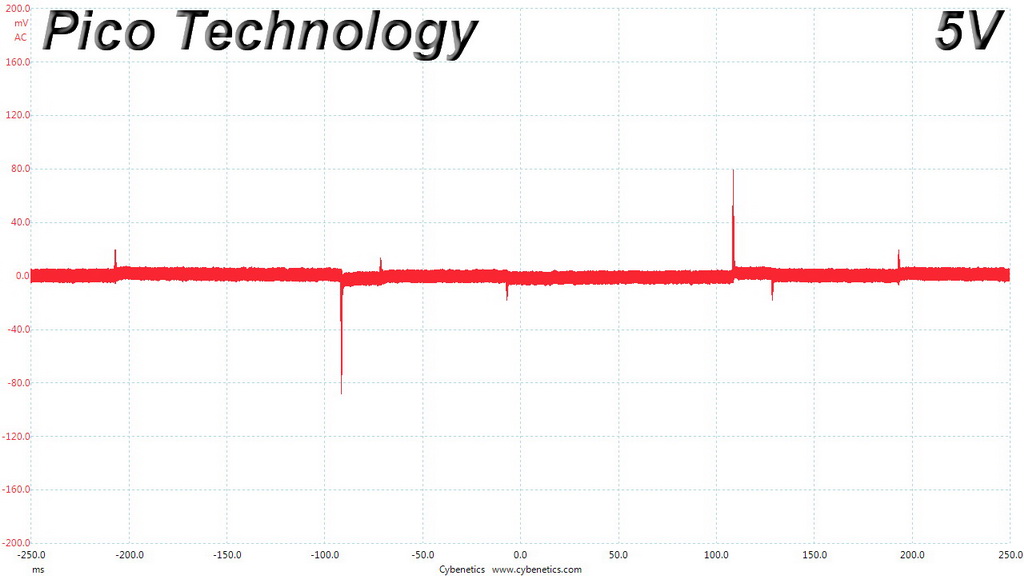
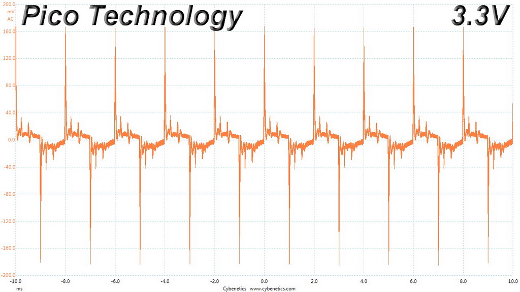
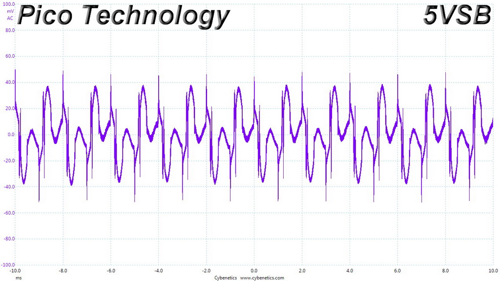
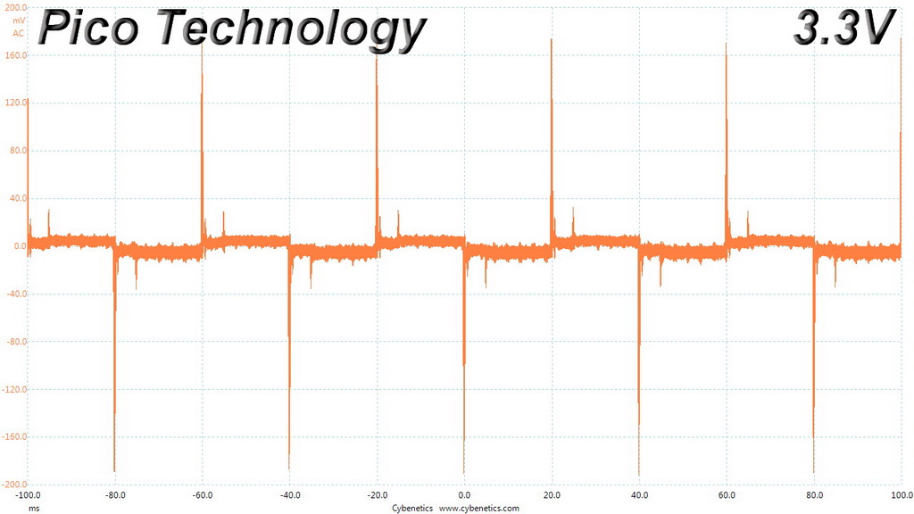
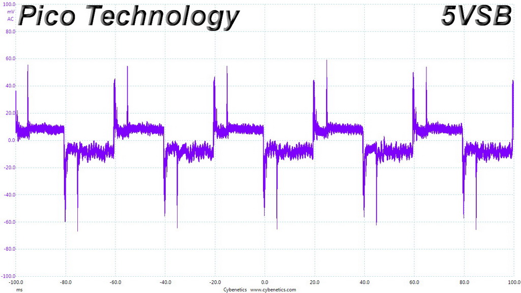
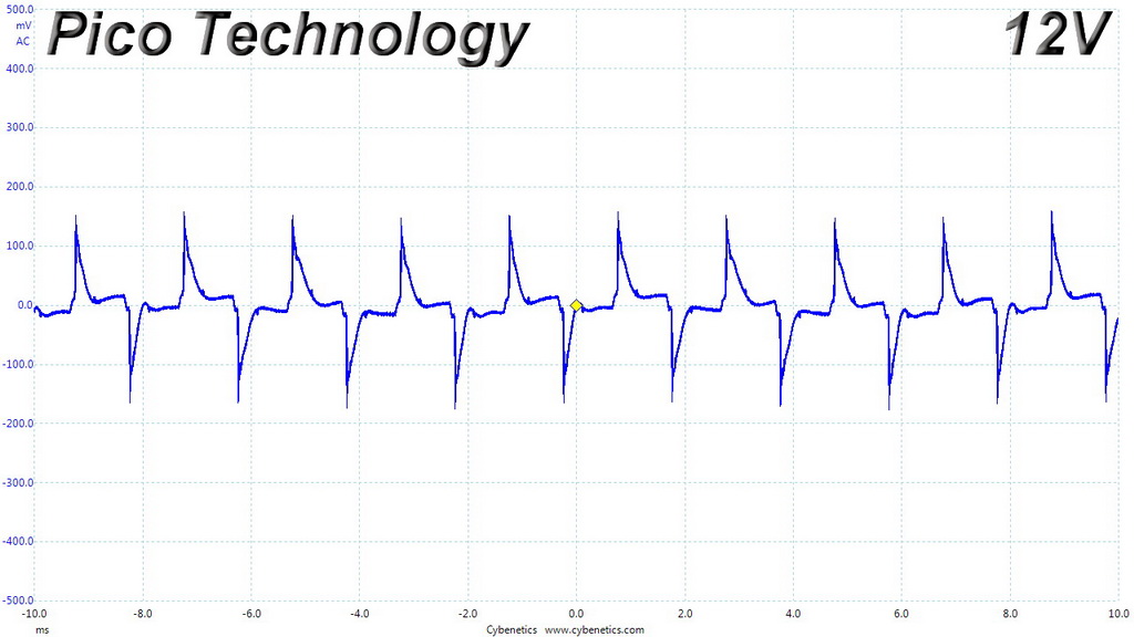
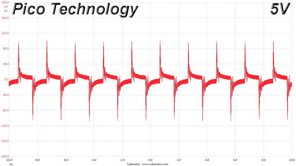
Ripple Oscilloscope Screenshots
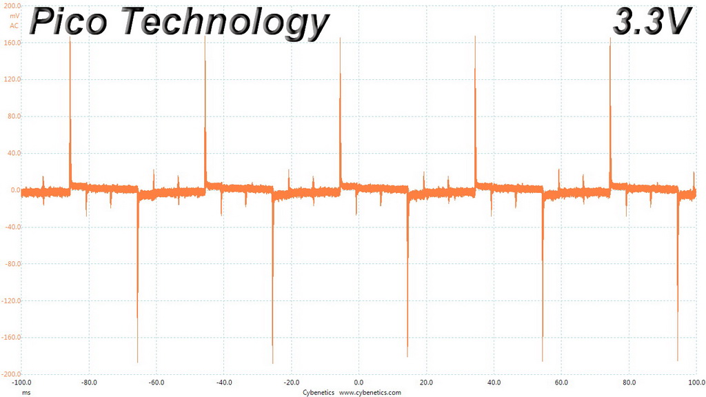
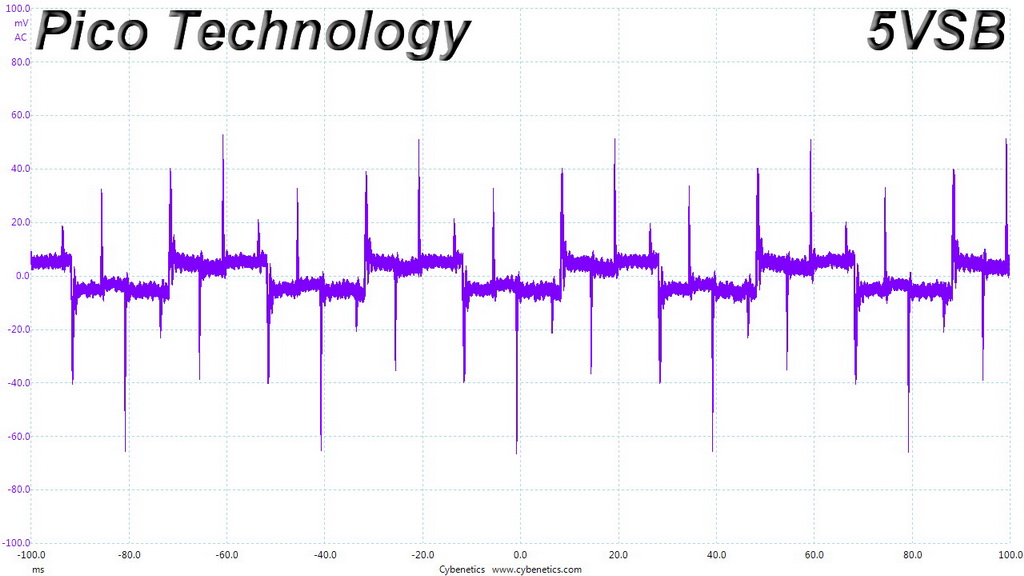
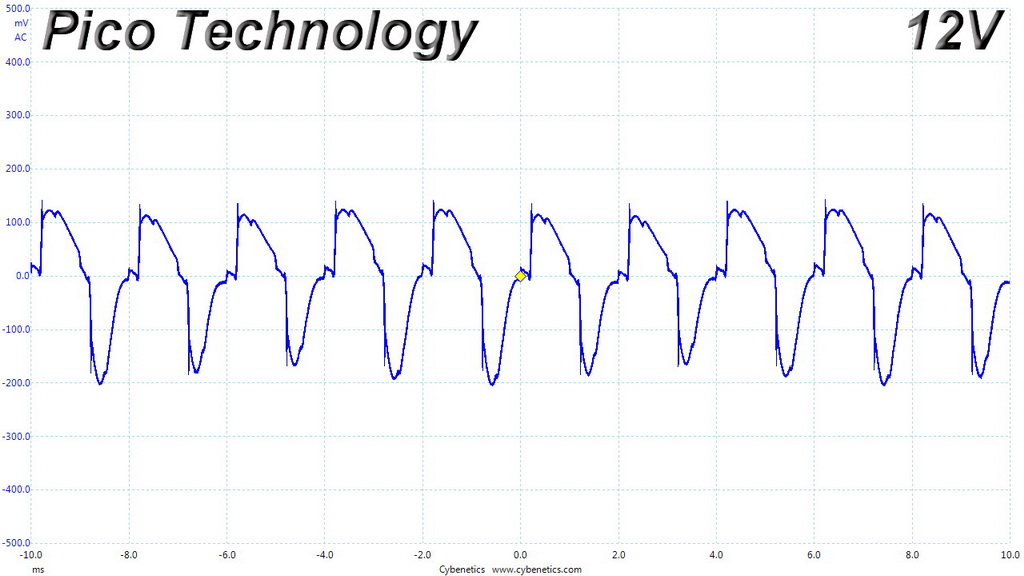
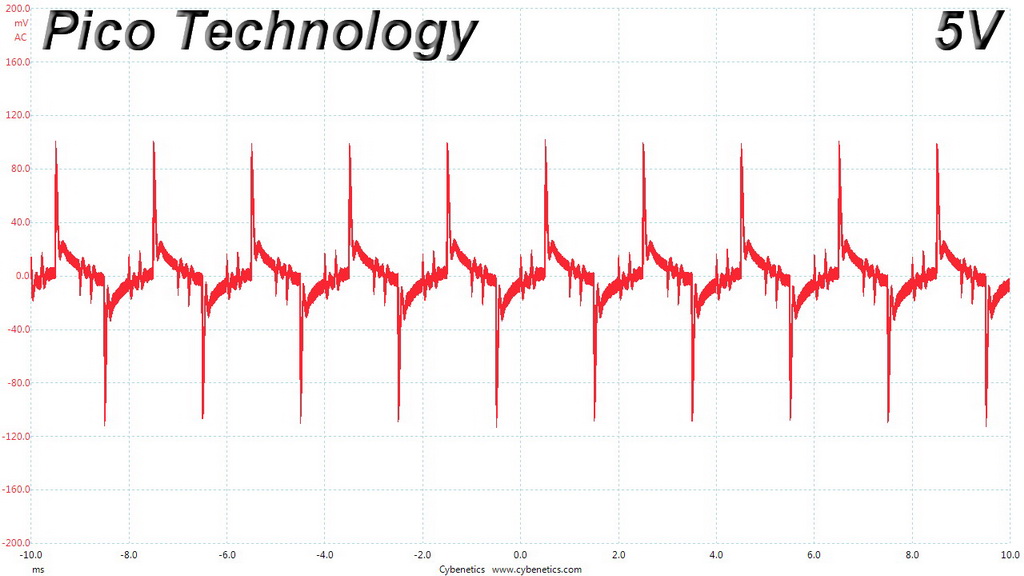
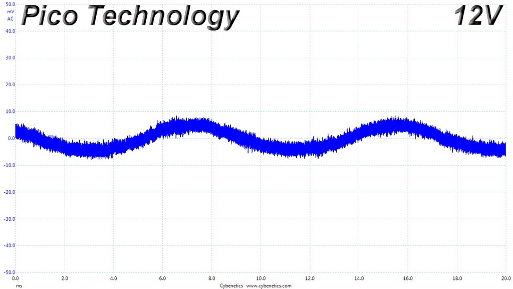
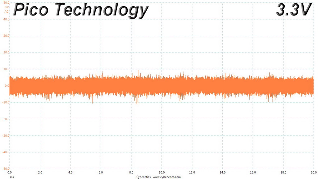
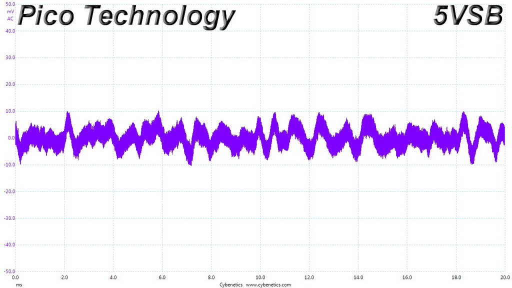
The following oscilloscope screenshots illustrate the AC ripple and noise registered on the main rails (+12V, 5V, 3.3V and 5VSB). The bigger the fluctuations on the screen, the bigger the ripple/noise. We set 0.01 V/Div (each vertical division/box equals 0.01V) as the standard for all measurements.
Ripple At Full Load

Ripple At 110-Percent Load
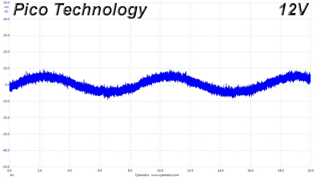
Ripple At Cross-Load 1
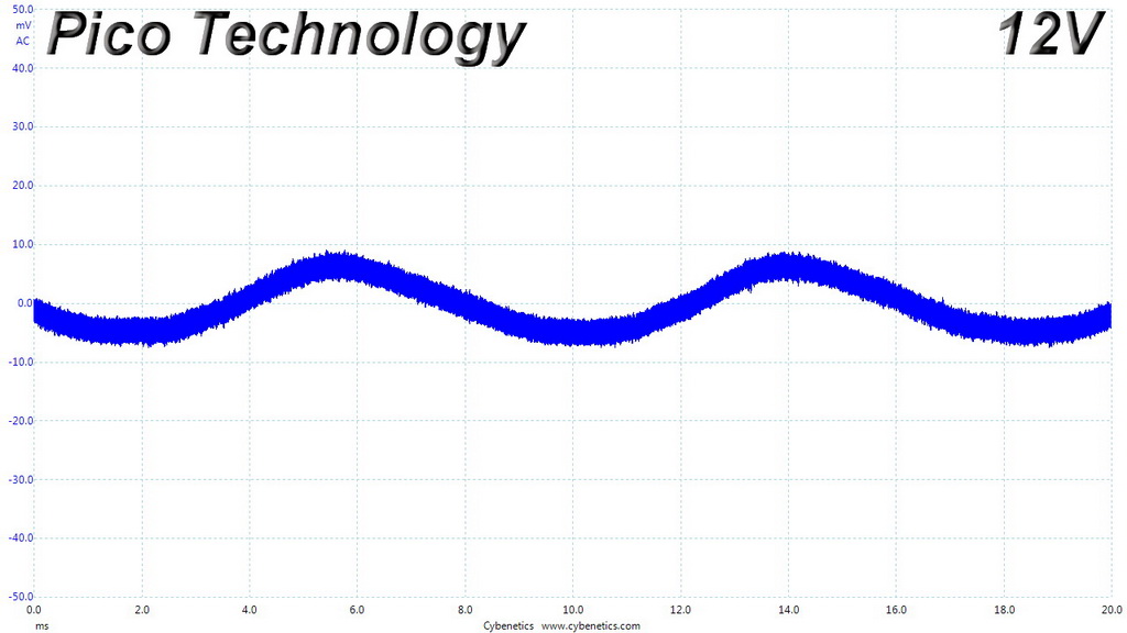
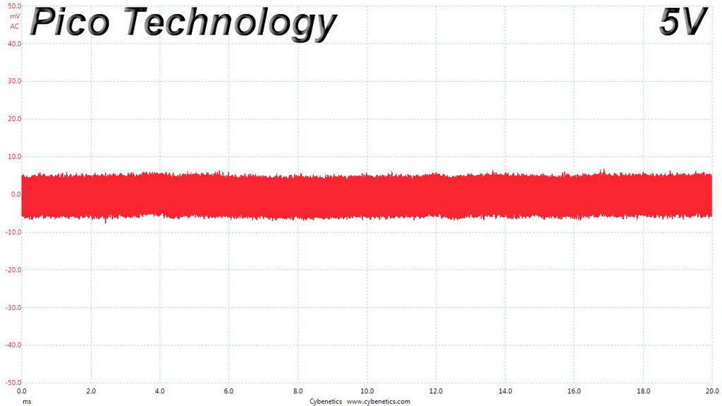
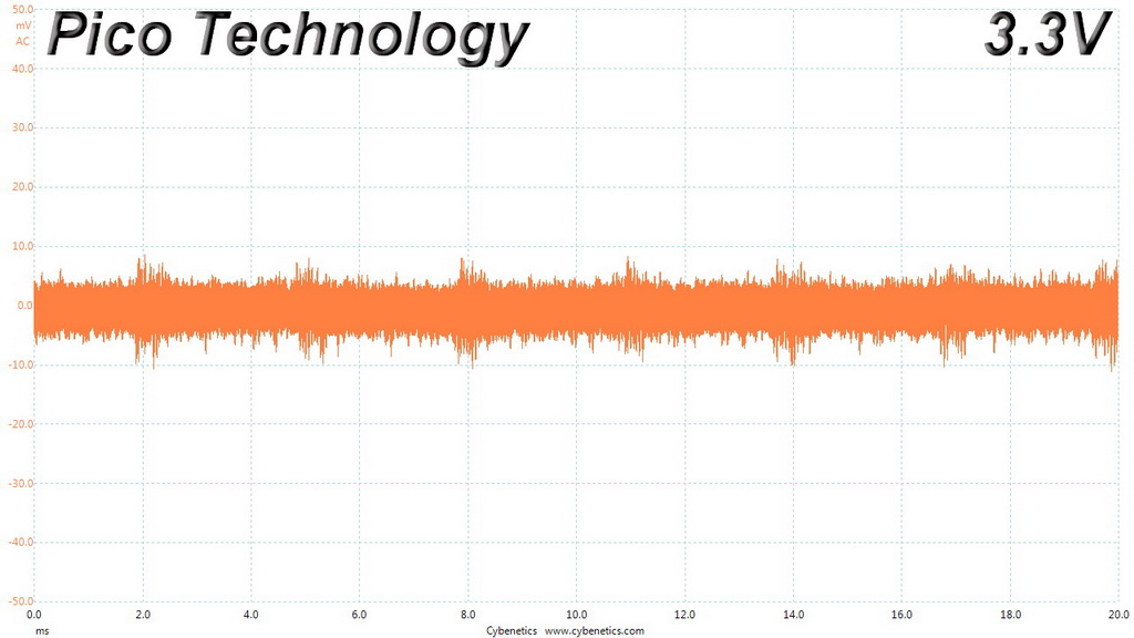
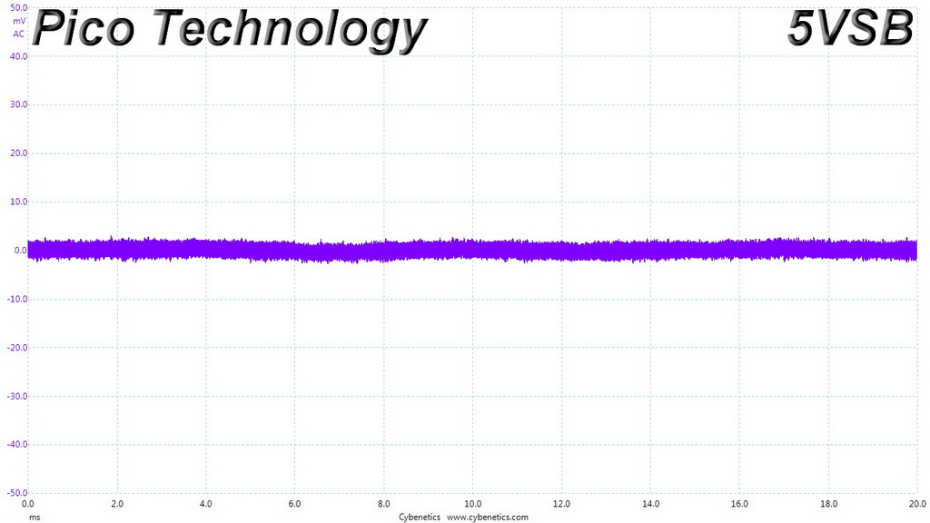
Ripple At Cross-Load 2
To learn more about our EMI testing equipment, please check out How We Test Power Supply Units.
EMI Results – Average Detector
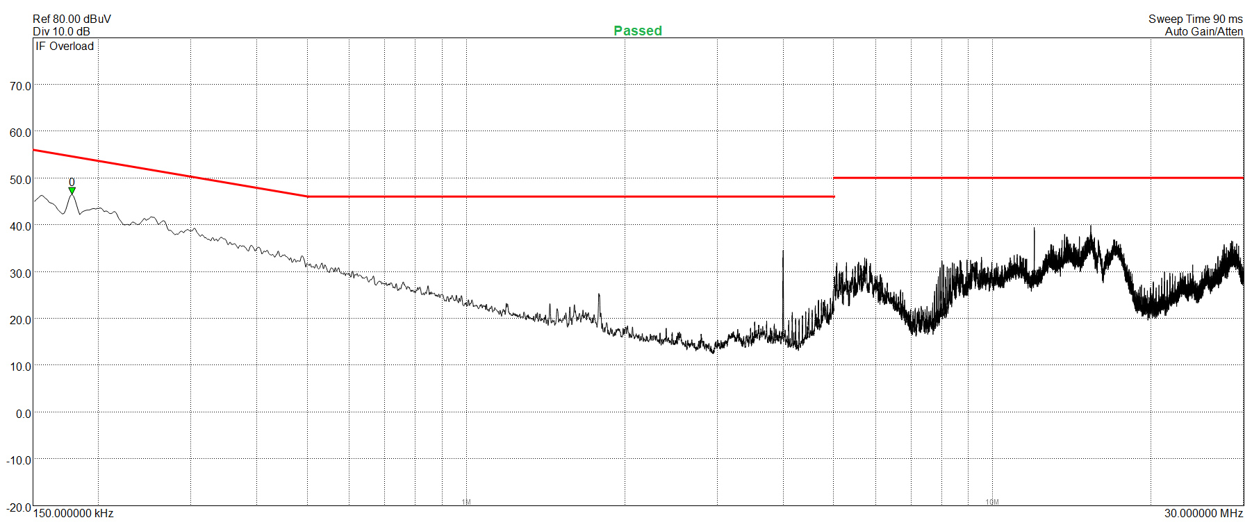
EMI Results – Peak Detector
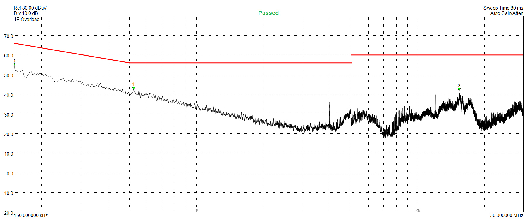
The conducted EMI emissions are low, thanks to this platform's highly capable EMI filter.
Performance Rating
The following graph shows the DQ850-M’s total performance rating, comparing it to other units we have tested. To be more specific, the tested unit is shown as 100 percent, and every other unit's performance is shown relative to it.
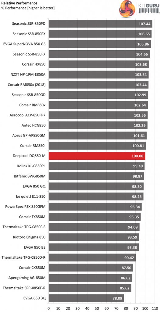 The overall performance is at a decent level, however still it is notably lower than the performance of units like the Corsair RM850x (2018), the Seasonic SSR-850FX and the EVGA 850 G3. With better transient response results and a longer hold-up time, this platform could be closer to the competition.
Performance Per Dollar
The following chart may be the most interesting to many of you because it depicts the product’s performance-per-dollar score. We looked up the current price of each PSU on popular online shops and used those prices and all relative performance numbers to calculate the index. Note that all of the numbers in the following graphs are normalized by the rated power of each unit.
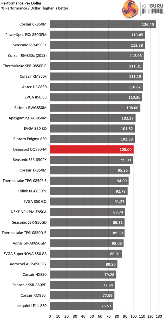
The product's price should be a bit lower, in order to allow for a higher price per buck score.
Noise Rating
The graph below depicts the cooling fan's average noise over the PSU's operating range, with an ambient temperature between 30°C and 32°C (86°F to 89.6°F).
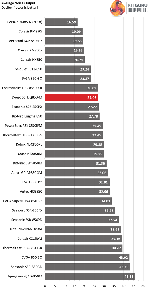
In the noise output section, only the RM850x manages to perform (notably) better, with the rest of the competitors being more noisy.
Efficiency Rating
The following graph shows the PSU's average efficiency throughout its operating range, with an ambient temperature close to 30°C.
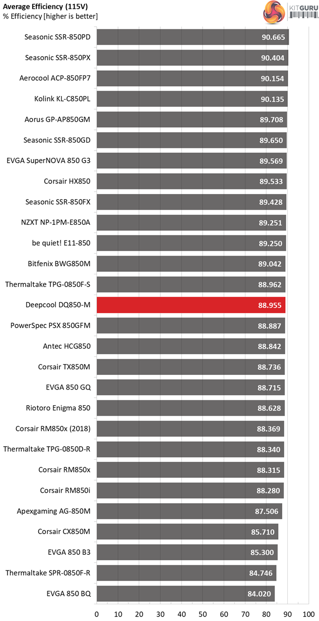
The Seasonic Focus Plus Gold platform along with the Super Flower Leadex II are more efficient, while the Corsair RM850x stay a bit behind.
The Deepcool DQ850-M retails for $129.99 (without VAT) in the US while in the UK market it is sold for £119.99 (including VAT).
Deepcool's new PSUs look promising, since they are based on a capable platform provided by Channel Well Technology (CWT). The build quality is very good and they are using high grade parts including Japanese capacitors, Infineon, Champion and On Semiconductor FETs along with a fluid dynamic bearing fan which according to Deepcool will have an extended lifetime.
It is nice to see something different in this popular capacity range. With the end of the mining era (for GPUs) mid capacity PSUs (650W to 850W) are very popular since they can support a wide range of capable gaming systems.
The DQ850-M features an attractive external design and offers high enough overall performance, which could be even better if the hold-up time was longer and the transient response at +12V and 3.3V was tighter. For a longer hold-up time apparently a larger bulk cap is needed and these are expensive. Be as it may, the ATX spec asks for more than 17ms hold-up time so every PSU claiming that it meets this spec should comply.
As for the transient response performance, the heavy use of polymer caps doesn't help since these type of caps don't offer the required capacity. For lower voltage drops under sudden loads more electrolytic caps are required – to raise the overall capacity in the secondary side (or a smart design). 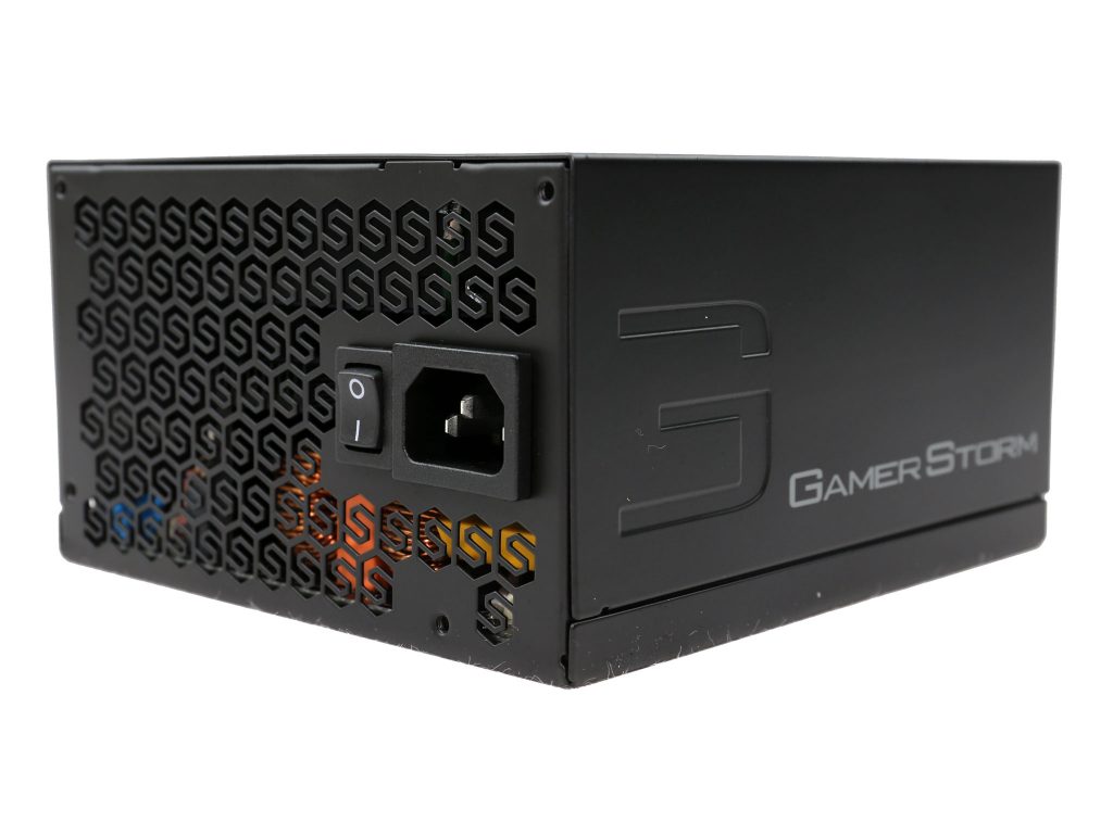
Deepcool's new 850W Game Storm unit is good, however given the overall performance score that it achieves it should be offered at a lower price, in order to be more competitive. It faces strong competition from Corsair's RM850x and Seasonic's SSR-850FX models, both of which cost around 110 bucks while achieving higher than the DQ850-M overall performance scores.
The only section where the DQ850-M has an advantage over the SSR-850FX is the noise output since it is notably quieter, however it is still behind the RM850x which is among one of the quietest 850W power supplies that money can buy today.
You can buy this unit from Amazon for £109.99 HERE
Pros:
- Delivered full power at 47°C.
- Efficient.
- Tight enough load regulation.
- Good ripple suppression.
- Quiet (LAMBDA-A- in the Cybenetics scale).
- High build quality.
- Low conducted EMI.
- Accurate power ok signal (but notably lower than 16ms).
- FDB fan (which should be larger than 120mm though).
- Fully modular.
- 5-year warranty. [25/9/18 Update: Deepcool informed us that the provided warranty has been extended to ten-years]
Cons:
- More expensive than the competition.
- Low hold-up time.
- The transient response at +12V and 3.3V needs improvement.
- Should have more than 4x PCIe connectors.
- 20AWG gauges for the peripheral cables.
- One of the EPS cables shares the same +12V rail with a PCIe cable.
KitGuru says: The Deepcool DQ850-M is a good PSU which faces stiff competition. Its major assets are the quiet operation, distinctive looks and high build quality, while the notable cons include the low hold-up time and the slightly high retail price. We would like to see a slight price drop to make it more competitive – we reckon a price around £100 inc vat in the UK would be ideal!