

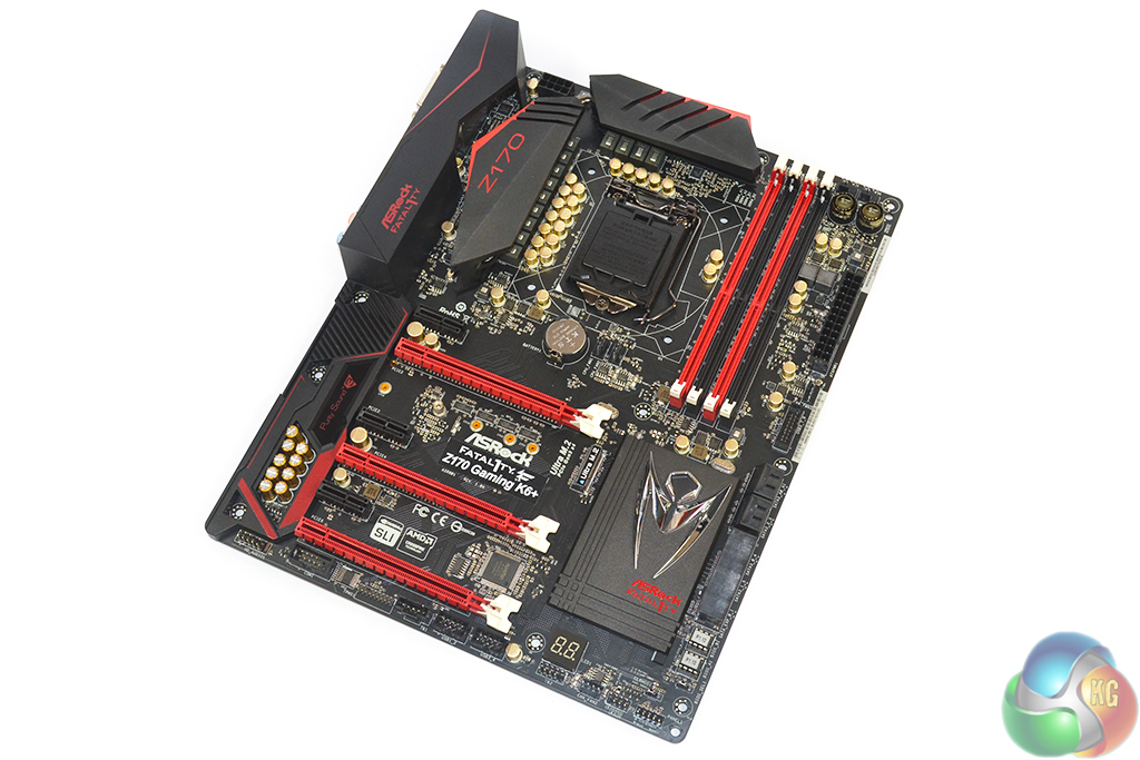
Clearly targeting gamers and enthusiasts who are still fond of the red and black colour scheme, the ASRock Fatal1ty Z170 Gaming K6+ is also outfitted with a styled rear IO cover. The plastic piece compliments the board's styling and is home to additional marketing names, but it also serves the purposes of preventing ESD damage.
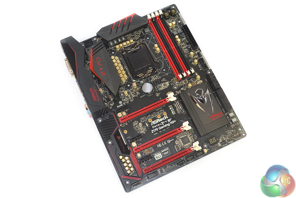
I am glad to see that ASRock has used a fully black PCB for the Gaming K6+. Whether in a low light or brightly lit chassis environment, there is no worry of having to withstand the ugly eye sore that is a brown PCB.
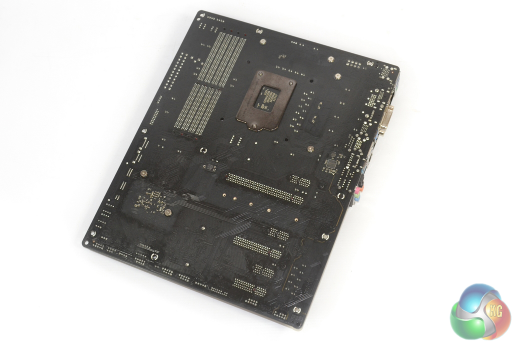
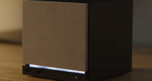
The board's rear side is home to the added USB 3.1 controllers and gives an insight into the physical PCIe lane configuration.
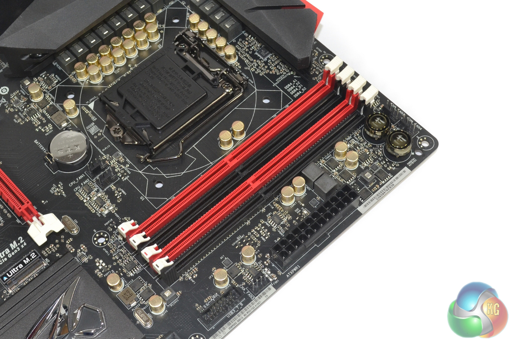
Support for up to 64GB of DDR4 memory is provided by the quartet of single-latch DIMM slots. ASRock states maximum memory frequency support of 3600MHz via overclocking, although the actual speed capability will be tied to partnering hardware. Two phases worth of physical components drive the memory.
I know many people may criticise the contrast that white DIMM slot latches create, although there will also be an equally large number of consumers who welcome the bright accent.
Along the motherboard's edge are the 24-pin power connector, a 4-pin controllable fan header, and the board's only internal USB 3.0 header. Clearly ASRock is confident enough in its front USB 3.1 panel to offer only a single USB 3.0 header when many competitors are supplying two. Power and rest buttons, as well as a further two 4-pin fan headers, are found in the board's top-right corner.

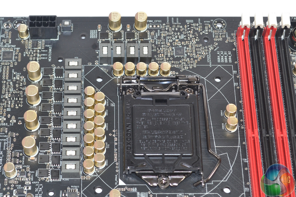
Thirteen physical power delivery phases surround the LGA 1151 CPU socket, although these will be split between driving the CPU, iGPU, and system voltages, with the CPU itself receiving eight phases (judging by the partnering components). A pair of hefty aluminium alloy heatsinks, connected via a heatpipe, cool the power delivery MOSFETs.
Power delivery hardware consists of Sinopower SM4337 and SM4336 high- and low-side MOSFETs, which are used alongside 60A chokes, and Nichicon 12K-rated ‘Platinum' capacitors.
Intersil's ISL95824 hybrid-digital PWM controller is deployed and can manage up to 4+2 phases. A pair of rear-mounted ISL6625A dual-MOSFET drivers (marked 5AZ XDK) from the same vendor help to provide coverage for the entire CPU portion of the power delivery system. So the CPU is effectively driven by four control channels, but eight physical phases. The remaining two controller phases seem to cater for the iGPU, with assistance from driver hardware.
An IDT6V41542NLG controller is responsible for managing the BCLK frequency range that is now truly unlocked with Intel's 6th Generation Core processors.
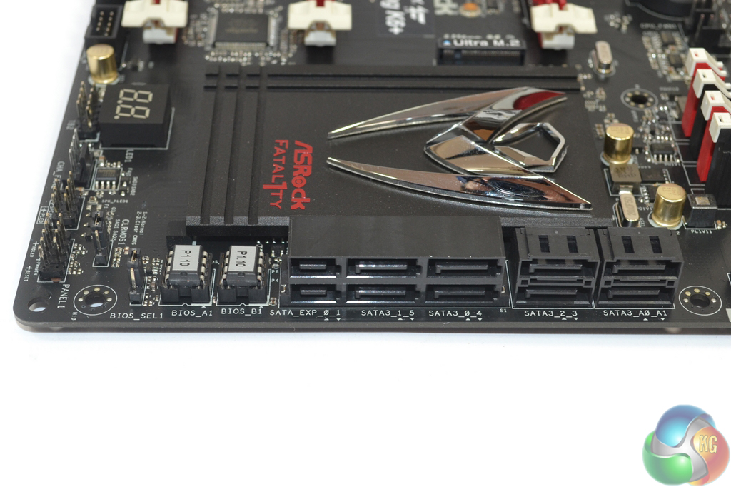
Dual socketed BIOS chips provide redundancy in the case of a UEFI crash. This is an inclusion which adds cost, albeit a small amount, but also enhances motherboard resilience.
A total of eight SATA 6Gbps ports is provided, four of which double-up as a pair of 10Gbps SATA-Express connectors. The two far-right SATA 6Gbps connectors are provided by an ASMedia ASM1061 chipset, making them slower than the Z170 ports. They are unlikely to bottleneck a mechanical HDD but I would only use them when no other ports are free.
The 32Gbps Ultra M.2 connector features support for PCIe and SATA M.2 SSDs with a length of up to 110mm, and can also mount a U.2 adapter. Its flexible IO lanes are shared by one of the SATA-Express connectors (and its accompanying SATA ports) which renders it unusable when the M.2 port is populated. That leaves you with four high-speed SATA 6Gbps connectors and two slower SATA 6Gbps ports when an M.2 device is installed.
Add the SATA-Express requirement of the front USB 3.1 panel into the mix, and we start to enter a storage device conundrum. Using an M.2 SSD and the front USB 3.1 panel, two Z170 chipset SATA 6Gbps ports and two slower ASM1061-fed connections remain. That's probably still plenty for most consumers, although it does emphasise ASRock's smart decision to include ASMedia's add-on SATA chipset.
As a note, if your front USB 3.1 panel ports do not seem to be working when you use an M.2 SSD, trying utilising the other SATA-Express connector.
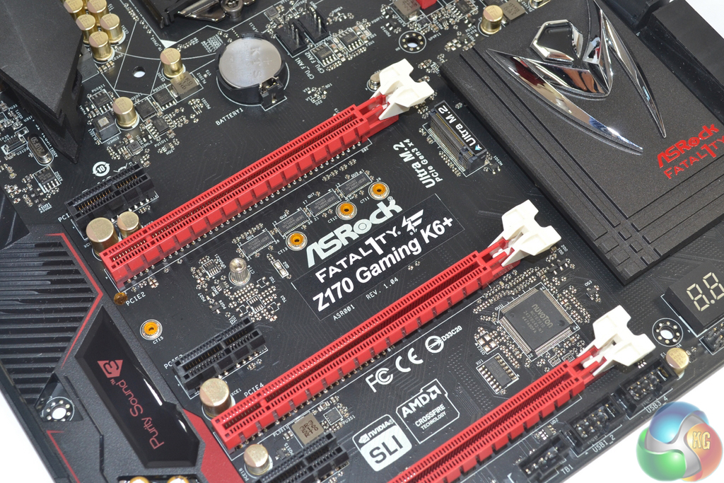
Expansion slots for ASRock's Fatal1ty Z170 Gaming K6+ follow the typical design that we expect to see from an upper-mid-range, gaming-orientated Z170 motherboard. Two-card SLI and three-card CrossFire is supported. ASRock's slot spacing is as good as it gets for an ATX board with dual-card usage in mind, and placement of the Ultra M.2 slot allows an ugly green SSD to be hidden by the graphics card above, albeit while receiving extra heat.
In single-card operation, the uppermost PCIe x16 slot receives a full sixteen-lane signal. Put an additional graphics card into the second full-length slot and the CPU's PCIe 3.0 lanes will be split as x8/x8. That lower full-length PCIe slot is electronically wired for a PCIe 3.0 x4 link from the chipset.
I prefer the chipset-linked approach for the third slot because it means that a user can happily operate a pair of graphics cards in the two high-bandwidth, CPU-fed PCIe slots (Nvidia SLI demands x8 connections, remember) and then use a device (such as an Intel SSD 750) in the remaining slot. While this adds extra latency for a PCIe SSD in the chipset-fed slot, linking all three connectors to the CPU lanes would foul multi-GPU configurations.
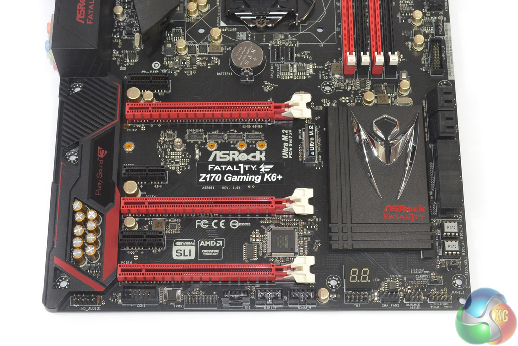
With that said, three-card CrossFire is possible thanks to its ability to function with x4 links, although I would not recommend it. If you want to run three graphics cards, you should be looking at investing in the X99 platform.
Three open-ended PCIe 3.0 x1 slots bolster the board's expansion capacity. These slots are likely to run from the chipset's flexible IO lanes, so do not be surprised to see some of them rendered unusable if other interfaces (such as the PCIe x4 slot) are utilised.
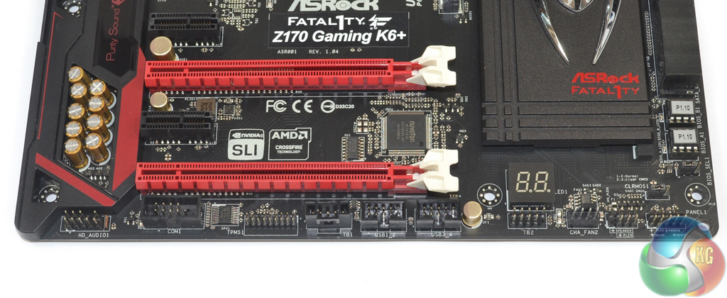
Two USB 2.0 headers join the standard set of front panel connectors and audio link along the motherboard's bottom edge. ASRock also includes COM and TPM connectors, as well as a Thunderbolt link header and two-digit debug LED display.
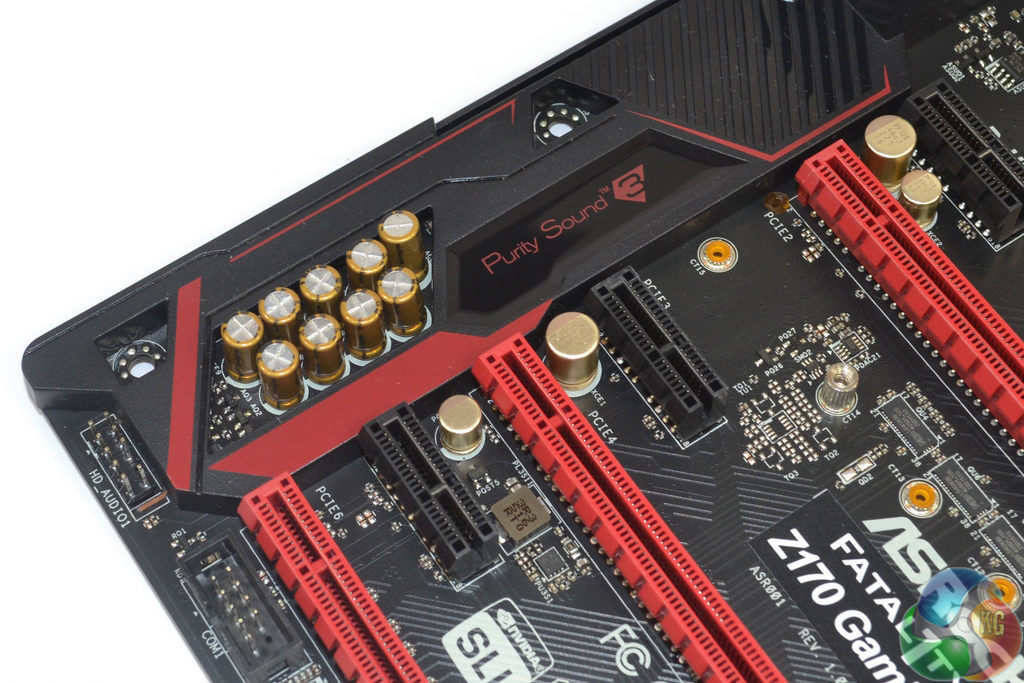
ASRock's Purity Sound 3 audio system is based around the Realtek ALC 1150 codec. Two Texas Instruments NE5532 op-amps drive rear and front panel headphone jacks, while Nichicon capacitors filter the audio signals.
PCB segregation is used to separate the audio signals, however the Realtek ALC 1150 codec is deployed in an unshielded state – many motherboards ship with dedicated EMI shielding for the audio codec.
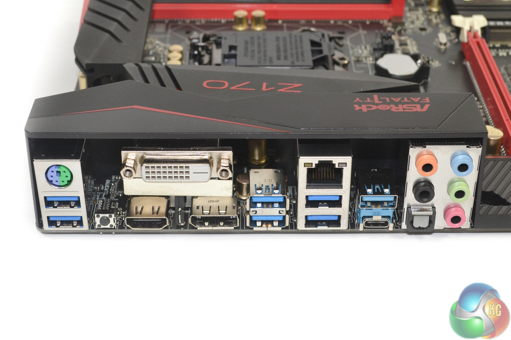
A total of six USB 3.0 ports are found in the rear IO section, all of which stem from the Z170 chipset. One of these connectors doubles up to form ASRock's Fatal1ty mouse port that features enhanced control adjustments through OS-based software. ASMedia's ASM1142 chipset feeds the pair of USB 3.1 ports, while an EtronTech EJ179V switch makes the reversible Type-C USB 3.1 connector physically possible.
Despite providing legacy keyboard and mouse support via the PS/2 connector, there are no USB 2.0 ports on the motherboard. This can hardly be deemed a negative now that the Windows OS is more USB-aware, although I would have liked to see two of the rear IO USB 3.0 re-assigned to an extra internal header duty, and then replaced by a pair of USB 2.0 connections. This is perfectly acceptable given that the Z170 chipset supports up to fourteen USB connections in total.
Gigabit Ethernet is provided by Killer's new E2400 series chipset. Network control in Killer's OS software remains one of its strongest purchasing points for motherboard vendors. HDMI, DVI-D, and DisplayPort 1.2 cater for high-resolution outputs from the iGPU. Audio connections are the standard affair and the venerable clear CMOS button is an always-welcomed addition to the rear IO.
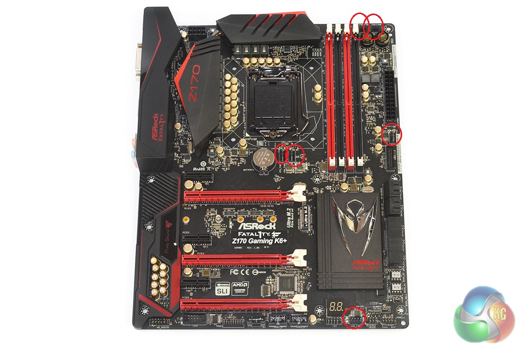
How effective you deem positioning of the motherboard's six 4-pin fan headers will depend on your system's components. Both 4-pin CPU fan headers are actually positioned below the socket, with the two connections in the upper-right corner being assigned chassis fan control. This will appeal to users of large air coolers as fan cables can hide under a fin array, but those with an AIO liquid cooler will not be impressed by the CPU headers' positioning.
With that said, ASRock's UEFI and OS tools, as well as the Nuvoton NCT6791D chipset's capabilities, mean that all of the fan headers feature extensive control options. So there's no harm in plugging your CPU cooler's fans into the chassis fan headers. Nevertheless, I would have liked one of the headers to be better placed for serving a rear chassis fan without sprawling cables.
Never understod your page “system” try limit it to fewer pages more in each, much easier for everyone
Which system page do you mean? The system-related testing page? I try to split the pages so that one of the pages doesn’t become a battle of never-ending scrolling through charts and charts.
Luke