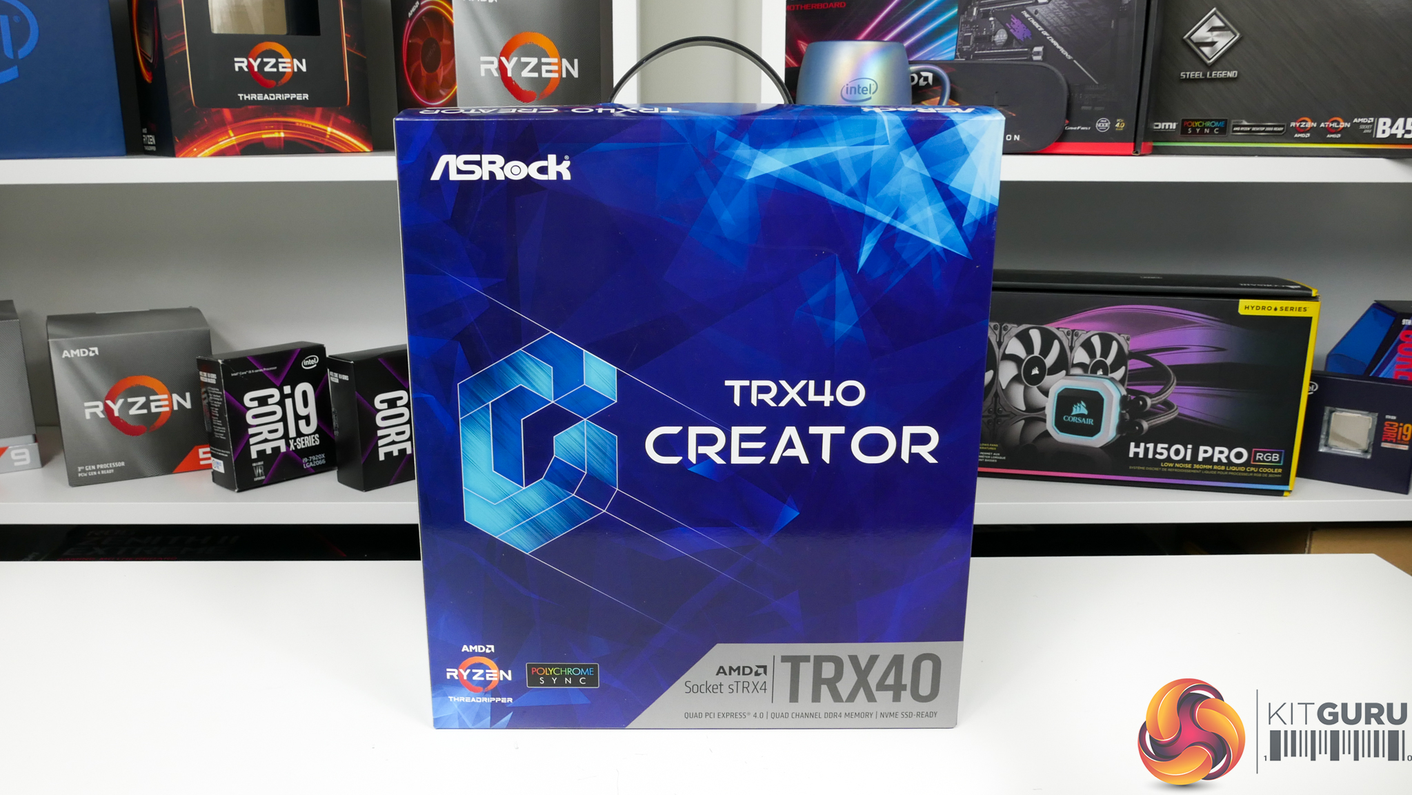
ASRock’s bundle for the TRX40 Creator includes a 2-way HB SLI bridge, the rear IO shield, SATA cables, wiring and antennae for the WiFi adapter, and screws for M.2 SSDs. The usual stickers, drivers CD, and paper manuals are also provided.
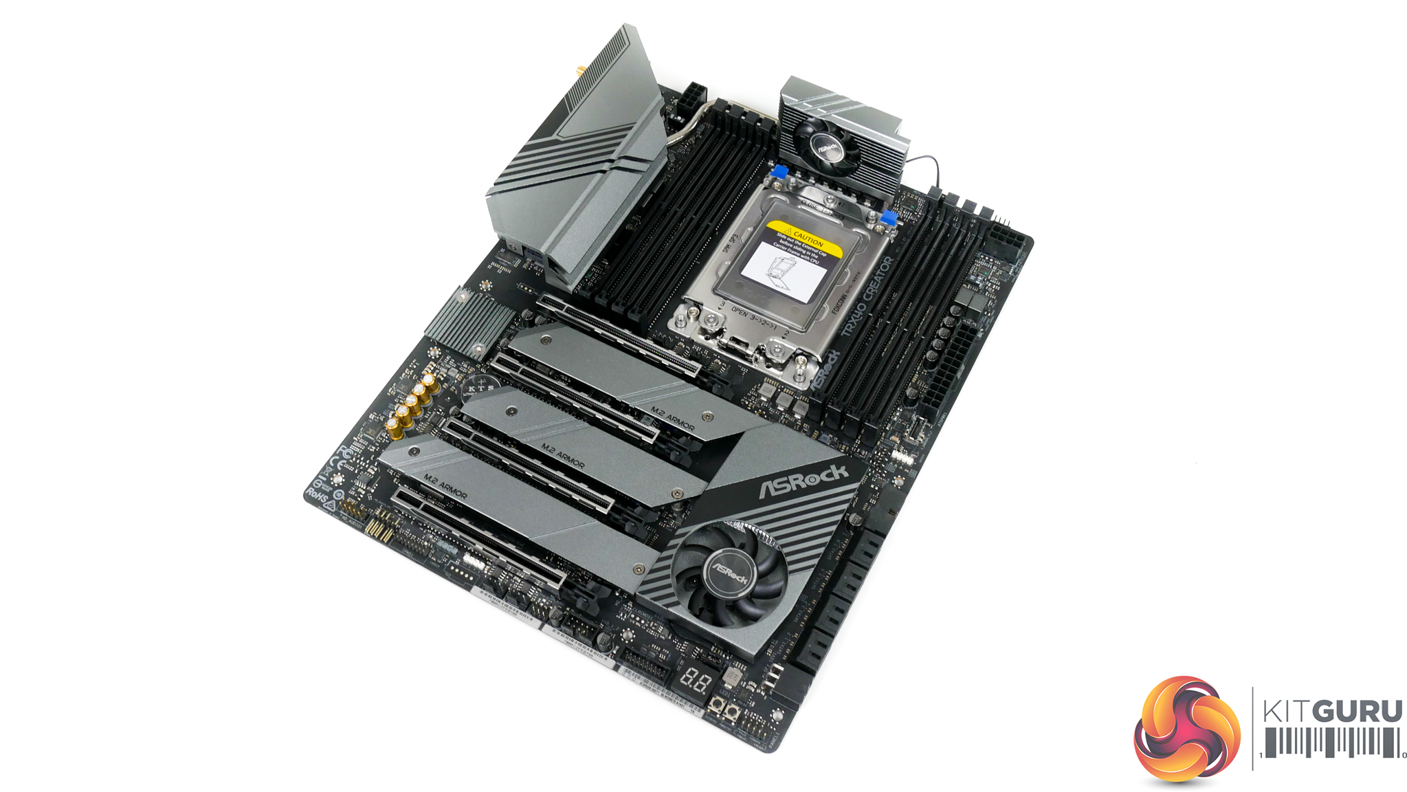
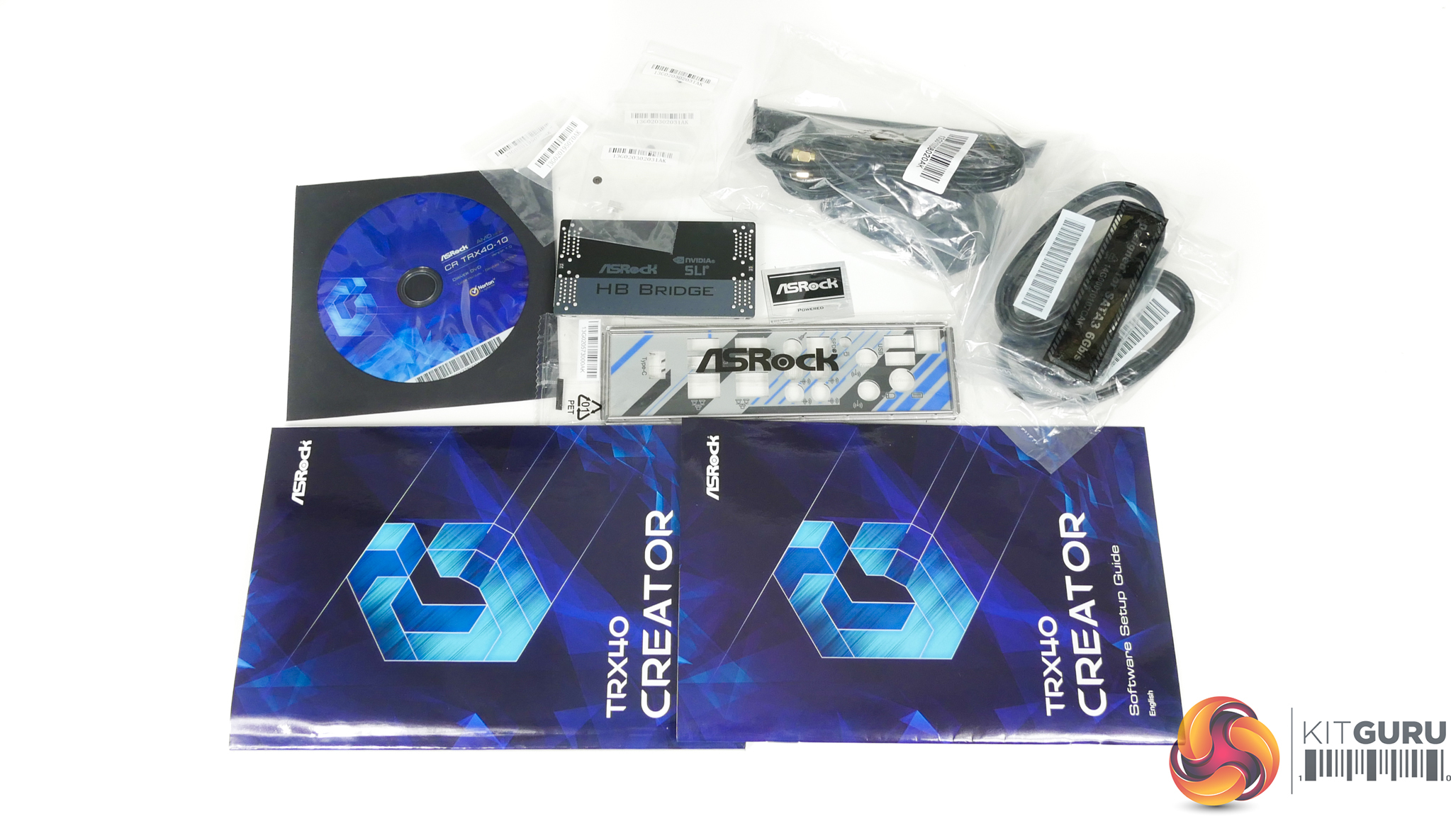
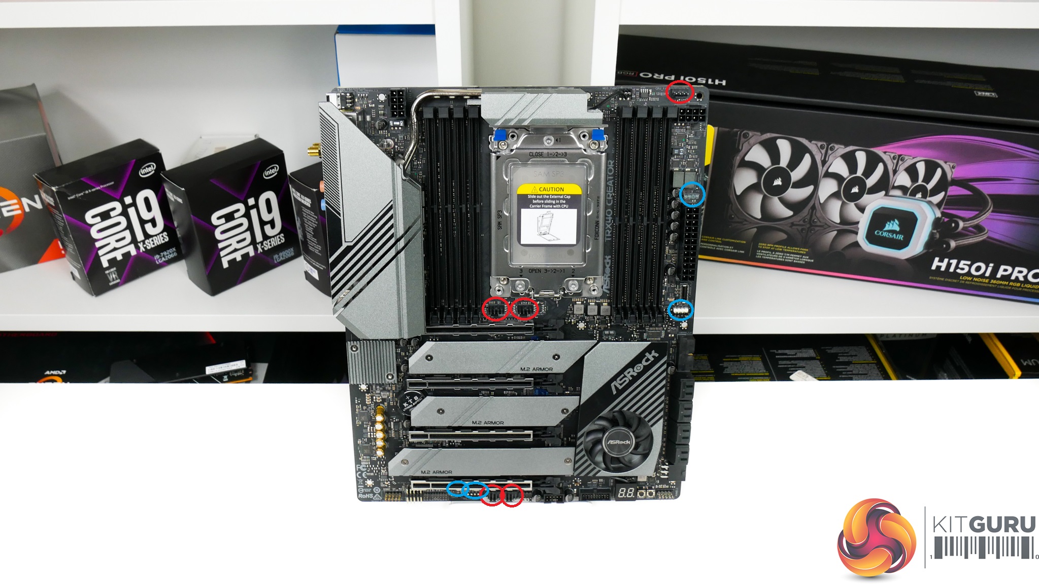
The ASRock TRX40 Creator uses a primarily black and silver/grey colour scheme across the motherboard. Areas most notable for their grey contrast are the heatsinks.
It is noteworthy that this motherboard does not feature any onboard RGB LED lighting, and I am perfectly happy with that. ASRock is clearly gearing this product towards creative professionals, many of whom will be far more interested in performance, stability, and value than flashy lights for their workstation.
With that said, there are still onboard RGB headers if you do feel the need to have separate LED strips mounted in your workstation chassis.
Typically, I would moan at the lack of onboard voltage measurement points. However, I feel that they are less important on a workstation-style motherboard where users are less likely to be tinkering with their system on a regular basis.
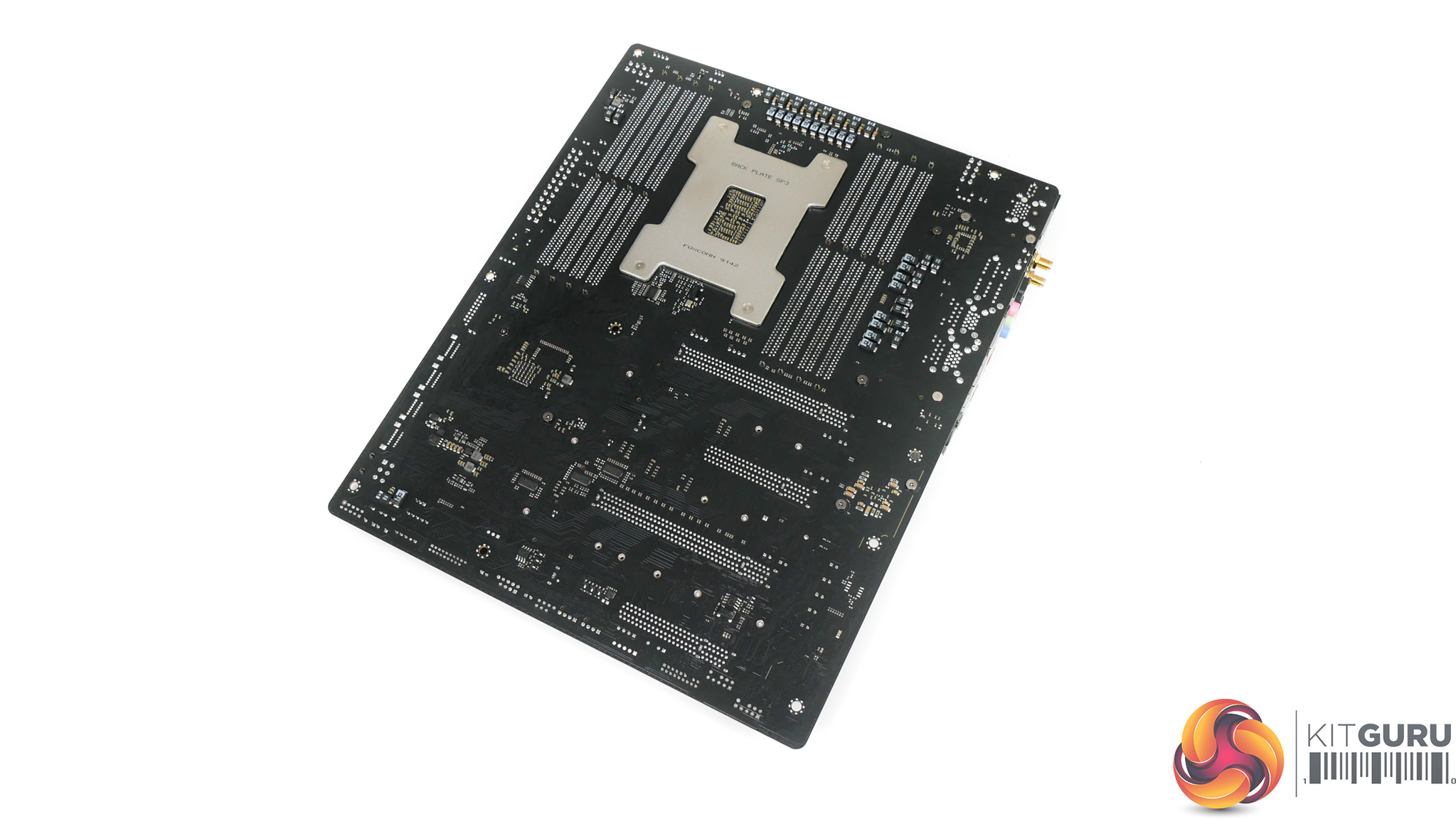
Flipping over to the rear side of the motherboard, we see the plain PCB without any form of heatsink or shielding in any area. This is interesting as competing products tend to use a small strip heatsink mounted beneath the primary MOSFET area, while others use a full cover backplate that contacts specific hot zones.
ASRock’s decision to omit any form of heatsink or metal shroud highlights a measure designed to save on costs and it also gives indication that the vendor is confident in the abilities of its chosen hardware to run at reasonable temperatures.
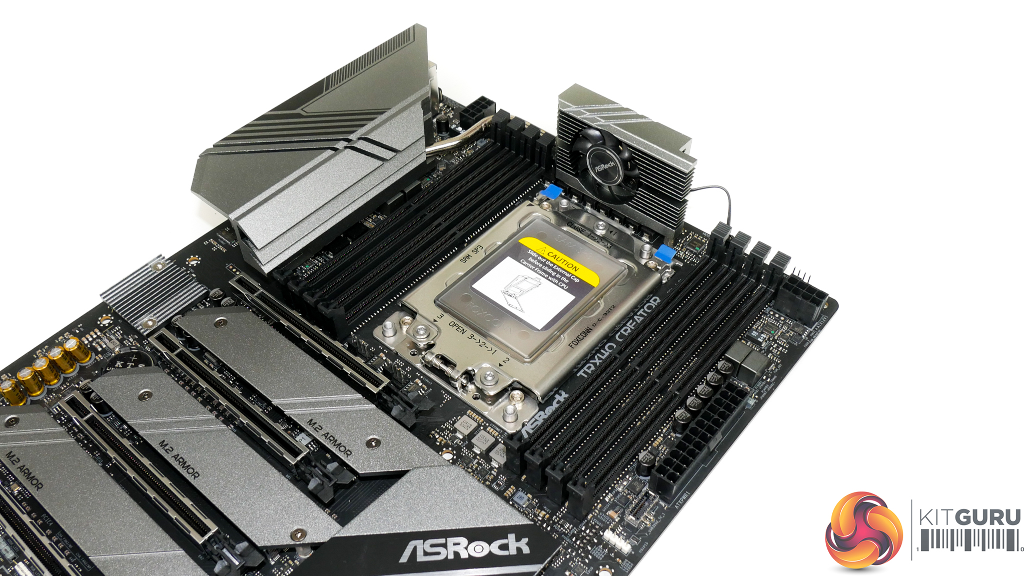
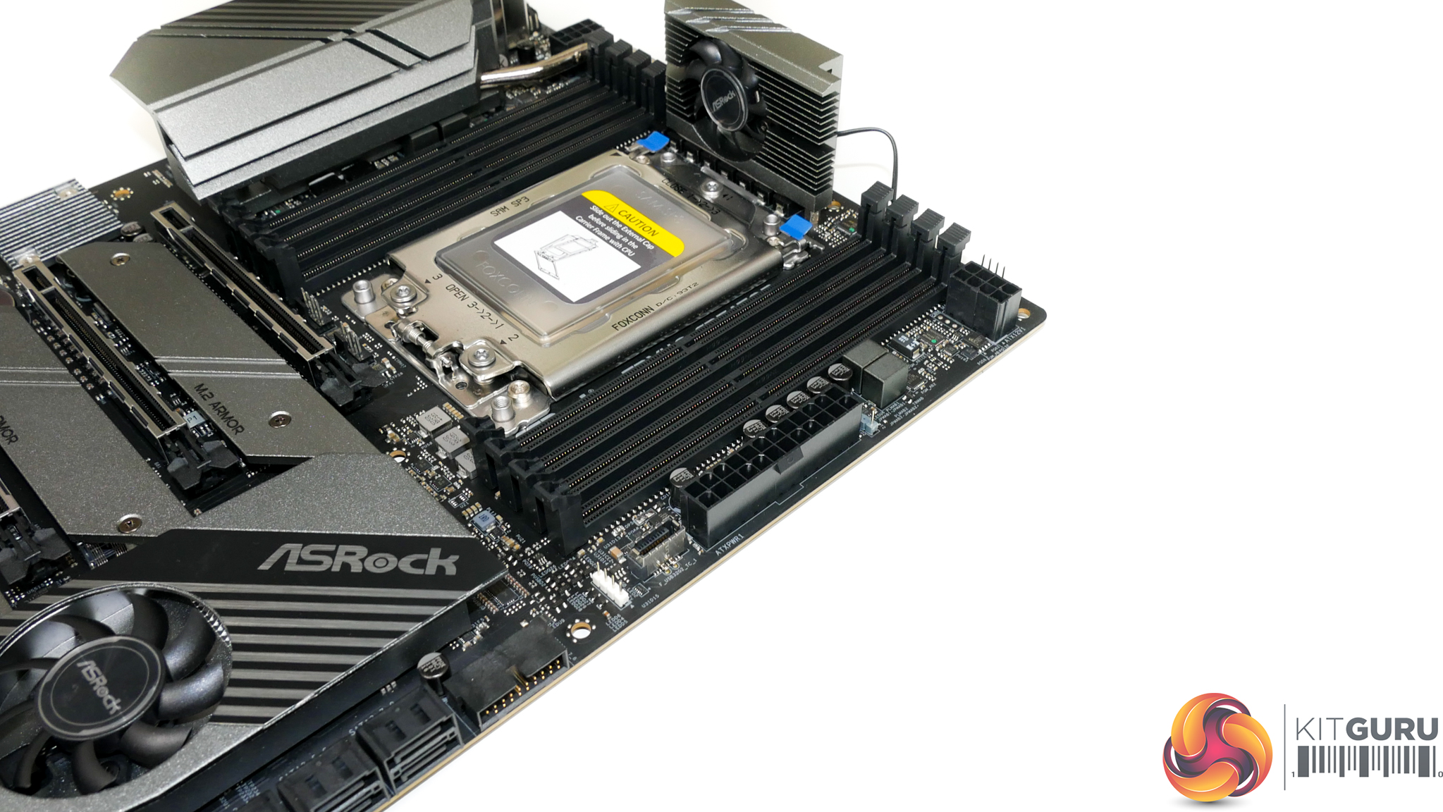
Eight DIMM slots with the single latch installation method are sat either side of the large sTRX4 CPU socket. ASRock quotes DDR4 frequency support well in excess of 4GHz, with 4266MHz modules from Corsair and HyperX specifically listed as compatible according to the QVL.
ASRock’s webpage also quotes support for both Non-ECC and ECC UDIMMs, though the memory QVL is clearly very light of information regarding ECC module compatibility.
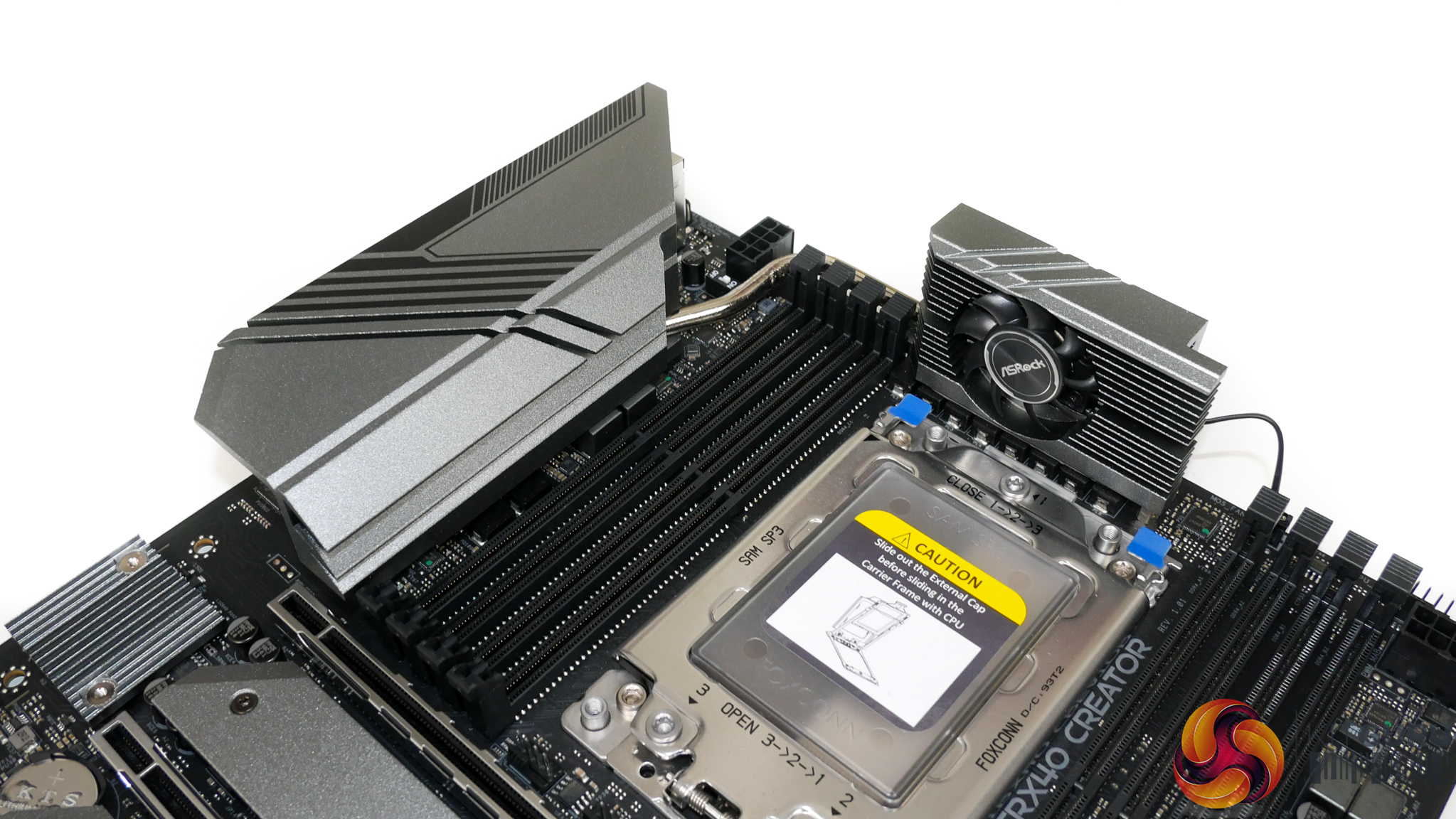
One of the more obvious design quirks is ASRock’s use of a taller-than-usual VRM heatsink positioned directly above the sTRX4 CPU socket. This height is dictated by the desire to mount the VRM fan vertically and it initially had me concerned with regards to CPU cooler interference.
I can, however, report that our sizable Cooler Master Wraith Ripper CPU cooler was able to fit without contacting the VRM heatsink. Clearance is in the order of millimetres, so it would seem that ASRock tested this possible conflict in the early design stages for the TRX40 Creator motherboard.
Noctua’s TR4 coolers are also likely to fit thanks to their sliding mount’s ability to adjust the heatsink mounting location.
Close to the 24-pin power connector you will find the usual pair of RGB headers in addition to the internal USB 3.2 Gen 2 10Gbps Type-C header.
It is pleasing to see ASRock sticking to the standard ATX form factor and width with the TRX40 Creator. While it certainly limits the amount of hardware and cooling that ASRock can physically fit on the motherboard, sticking with standard ATX sizing vastly improves compatibility with cases.
Dual 8-pin power connectors are used to feed the hungry Threadripper 3000 CPUs. As we saw with ASUS’ similarly priced competitor, ASRock positions these power inputs on opposite sides of the motherboard. Depending on your chassis, this may benefit you in terms of cable management or it may make the tidying process more difficult.
The decision looks to be driven by ASRock’s desire to connect the two VRM heatsink towers via a heatpipe that routes directly where the second 8-pin connector would typically be placed. ASRock also argues that splitting the CPU power connectors allows the VRM to be fed from two sides, thus improving efficiency and temperatures.
Either way, you get the dual 8-pin connectors that deliver the extra power delivery Threadripper 3000 CPUs demand when overclocked.
ASRock includes a physical switch on the motherboard that allows for some more extreme power delivery settings to be obtained. Realistically, we see no point in this addition on a professional-geared motherboard; perhaps it is a feature that has been left over from the more enthusiast orientated offerings in ASRock’s range.
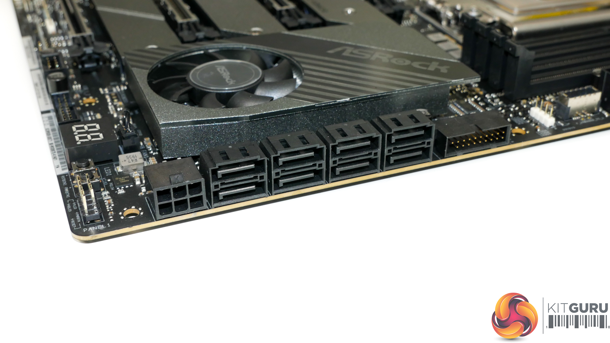
Eight SATA ports are provided by the TRX40 Creator – a number that I think is perfectly adequate for this motherboard’s target audience when the M.2 slots are also factored in.
ASRock makes no reference to bandwidth sharing between the SATA ports and other expansion devices, so a content creator can use all eight ports simultaneously.
Next to the bank of SATA ports is one of the motherboard’s two internal USB 3.0 5Gbps headers. This is mounted in a right-angled location which may ease cable management duties.
A right-angled 6-pin PCIe power connector is added to the motherboard in light of the four full-length PCIe expansion slots. It is not unreasonable to think that some users may install three or four high powered graphics cards on this motherboard, at which point the extra power delivered by a dedicated 6-pin connector is likely to be valuable.
One unique addition to the usual set of bottom edge connectors is a right-angled HD audio header. This is mounted next to the vertically orientated HD audio header and is clearly a design decision stemming from the bottom full-length PCIe slot that could house a large graphics card.
Moving along the bottom edge, we see TPM, RGB, two 4-pin fan, USB 3.0 5Gbps, and USB 2.0 headers. ASRock’s inclusion of only a single USB 2.0 header is disappointing as these prove widely used by AIO pumps, RGB controllers, and many cases. Disappointingly, there is no included Thunderbolt Add-In-Card header with the TRX40 Creator.
I like the inclusion of a two-digit debug LED and its mounting location is reasonable given that the top-right alternative location is likely to be covered by a large air CPU cooler. Simple onboard power and reset buttons are also useful additions for times of troubleshooting, so credit to ASRock for placing them on this motherboard.
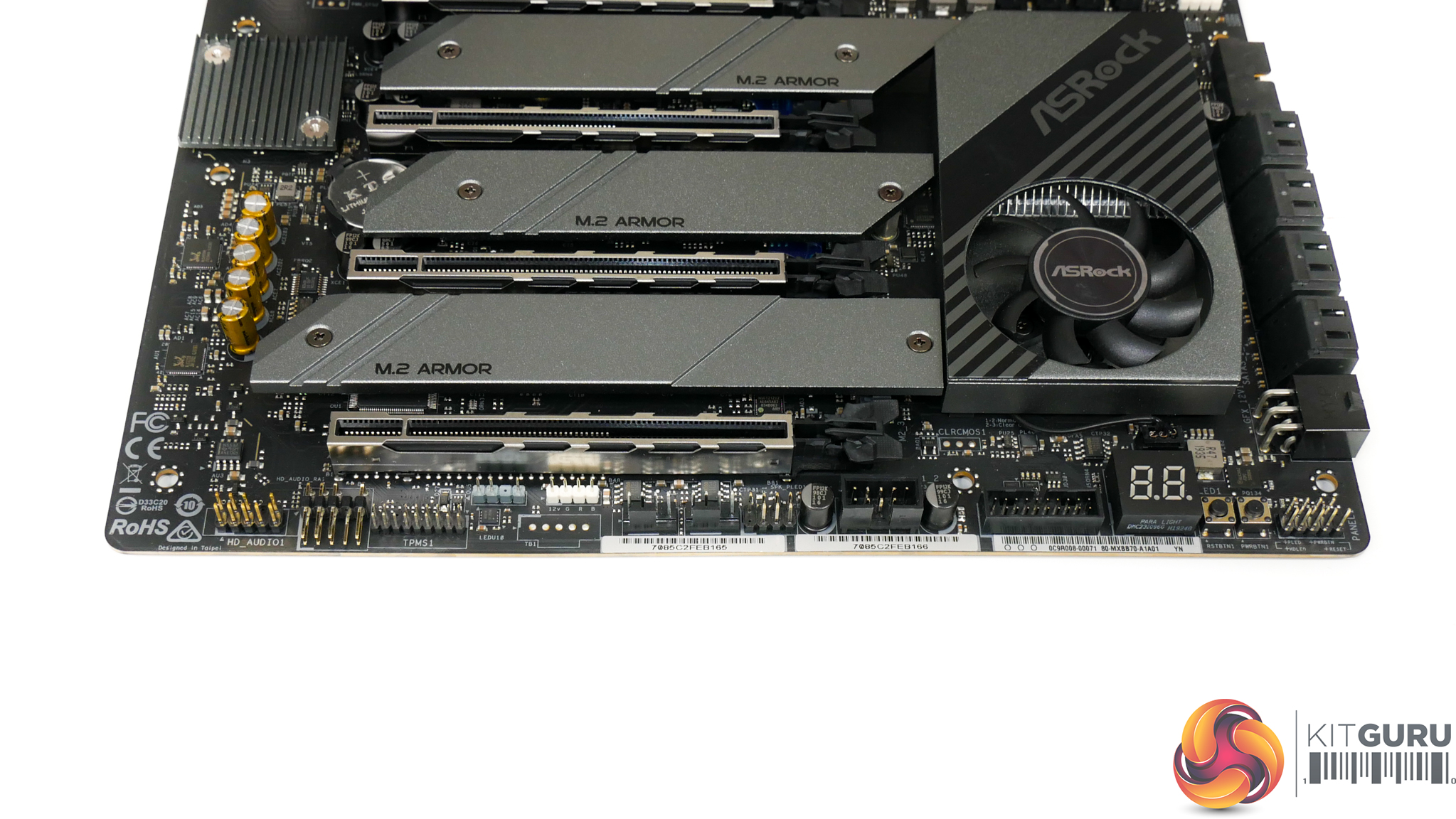
ASRock’s PCIe slot layout allows for the use of four dual-slot graphics cards or other expansion devices simultaneously. That point will be particularly important to some users such as those dealing with highly demanding rendering jobs, especially given that TRX40 Creator is one of the few sTRX4 motherboards to offer such capability.
While all of the PCIe slots are full length in size, the lane allocation (from top to bottom) is x16/x8/x16/x8. 4-way SLI and CrossFire are technically supported, but this configuration is more suited to users with demanding workloads in applications that can address multiple individual GPUs.
Alternatively, passing through high-end GPUs to four individual virtual machines is another worthy use case for this type of slot layout.
We must credit ASRock for this design decision. The compromises required are clear; the CPU socket is pushed up thus limiting the size allowance for the VRM and the PCB area that the heatsink can use. In addition, two triple-slot graphics cards will leave no other slots accessible, unlike some competing motherboards. But those trade-offs may be worthwhile to professionals with specific workloads that benefit from multiple expansion cards and the decision is one that allows the TRX40 Creator to truly live up to its ‘Creator’ name.
One clear area that needs consideration is CPU cooler interference with the top expansion slot. We could not install our Gigabyte RTX 2080 Ti Aorus Xtreme graphics card in the top slot as the card’s backplate interfered with the large Cooler Master Wraith Ripper CPU cooler. This is something to consider when choosing a relevant CPU cooler and a graphics card with a backplate.
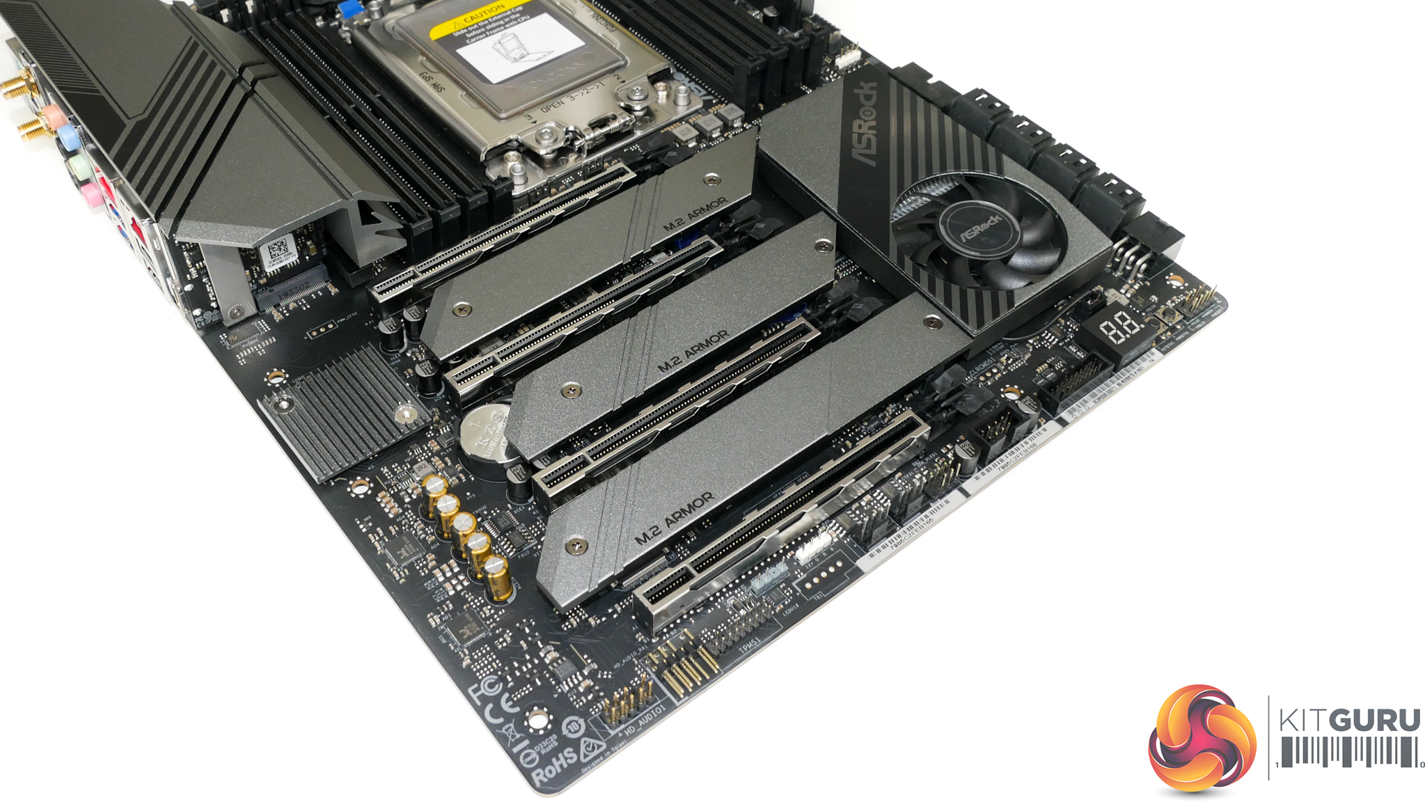
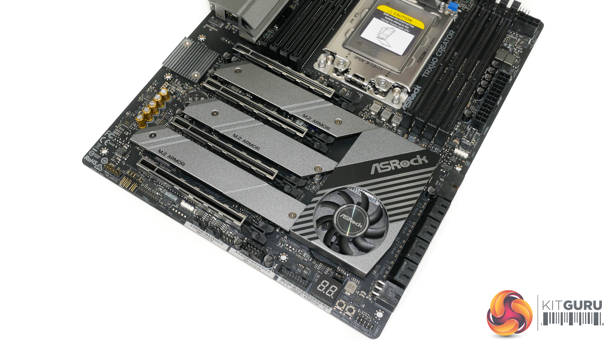
The TRX40 Creator is equipped with three M.2 slots, all of which sit between the PCIe expansion slots and beneath metal heatsinks. There is plenty of space beneath the individual, elevated heatsink strips. This may aid cooling as airflow can directly reach the SSDs beneath, although that also means that hot exhaust air from graphics cards can interact easily with the M.2 devices.
Both of the top two slots support drives up to 80mm long and can only be used with PCIe SSDs (up to Gen 4 x4 bandwidth). The bottom slot extends drive compatibility to 110mm-long M.2 devices and also adds support for SATA 6Gbps SSDs.
ASRock’s SSD installation method is simple and quick as only two screws need to be removed in order to provide access to the underlying M.2 connector. This also means that any of the M.2 slots can be used with a PCIe SSD with a large heatsink as ASRock’s strip heatsinks can be removed individually.
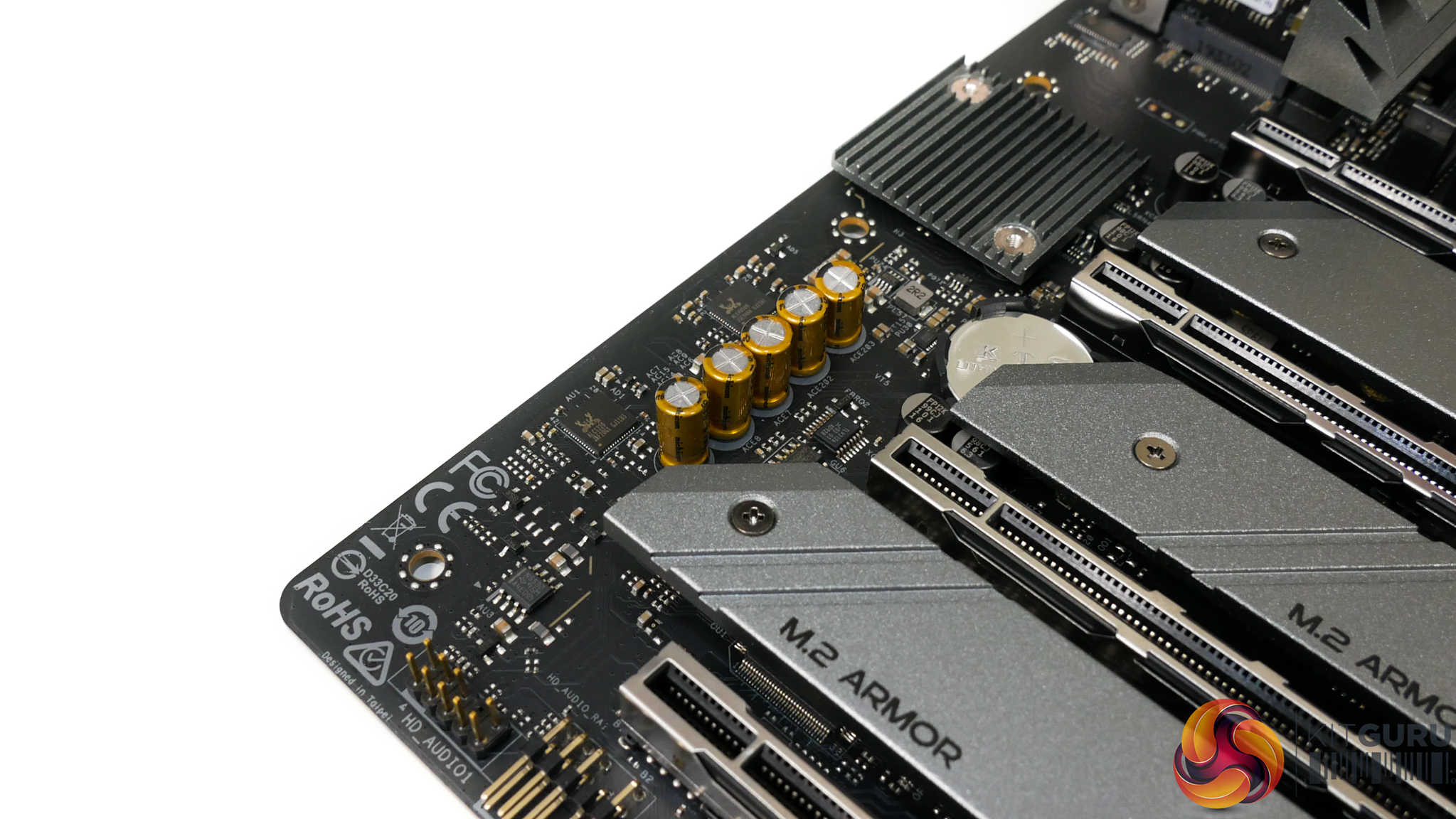
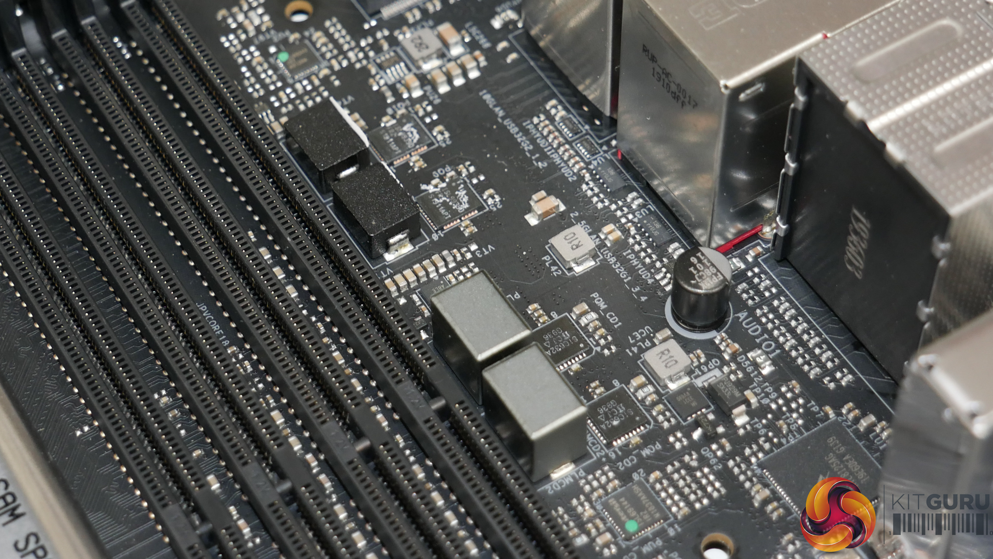
ASRock’s Purity Sound 4 audio system is built around the Realtek ALC1220 audio codec. The codec is powered by a USB 2.0 port from the TRX40 chipset and using a Realtek ALC4050H bridge as the TRX40 platform does not natively support onboard audio.
Located close to the pair of Realtek chips is a Texas Instruments NE5532 operational-amplifier and a bank of Nichicon Fine Gold series audio capacitors.
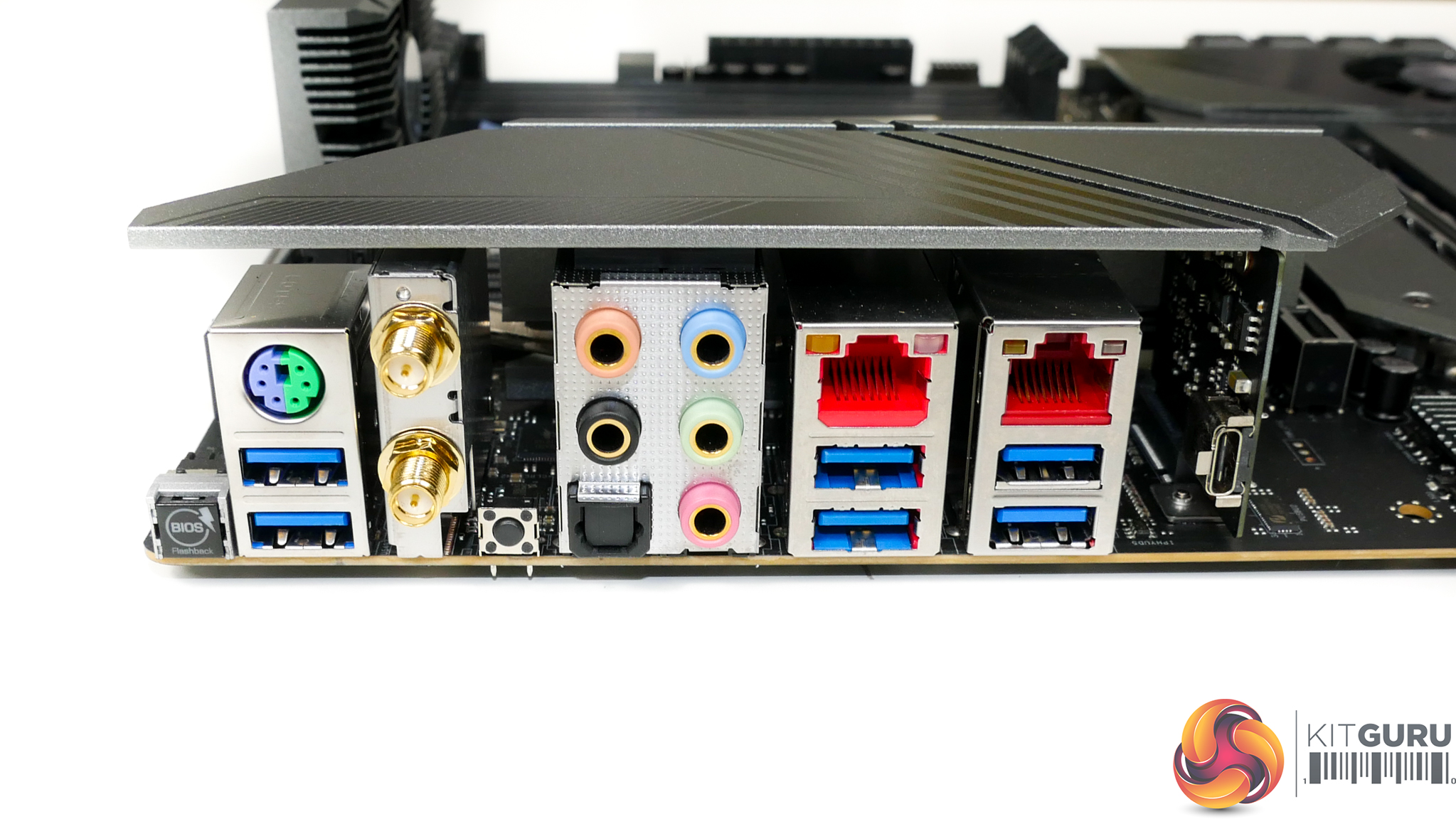
Star of the show for the rear IO is ASRock’s inclusion of 10 Gigabit networking via a standard RJ-45 Ethernet connector. The controller powering the 10GbE port is an Aquantia AQC107, which is mounted beneath a heatsink. Partnering the 10Gb Aquantia NIC is a 2.5Gb Realtek RTL8125AG controller.
It is good to see ASRock including a pair of high-speed NICs on a motherboard targeting creative professionals. Clearly, the 10Gb Aquantia NIC is of real benefit to those who push vast amounts of data across their 10Gb network or via a point-to-point server link. Equally so, the 2.5Gb NIC is a good sidekick for times when a 2.5Gb point-to-point or switched connection may be adequate.
Two USB 3.0 5Gbps port are mounted directly beneath a PS/2 combo port. Next to these is the pair of WiFi antenna plugs for use with the Intel 802.11ax wireless networking module. Moving further right, we see two more USB 3.0 5Gbps Type-A ports followed by a pair of 10Gbps USB 3.2 Gen 2 ports. The usual set of audio connectors is positioned towards the centre of the rear IO.
ASRock includes a single USB Type-C connector that is provided via a pre-mounted add-in-card. This Type-C port operates at USB 3.2 Gen2x2 bandwidth making it capable of up to 20Gbps transfer speeds. That’s a useful feature for users with demanding file transfer schedules in a system without Thunderbolt 3.
The inclusion of a BIOS Flashback button is now common on motherboards of this ilk, but the rear-mounted clear CMOS button is a positive inclusion. I’d say that clear CMOS button’s mounting location is smart to avoid accidental presses, given that users will infrequently connect or disconnect audio and WiFi antenna connections, unlike USB ports.
ASRock does not deploy an integrated IO shield, which looks to be a cost saving measure. This is a little disappointing for such a premium motherboard, but I think that it is reasonable for ASRock to omit this design feature for a small cost saving on a workstation-type motherboard.
You get a total of five 4-pin fan headers spread across the motherboard, three of which are within easy reach of the CPU socket. Five headers is borderline adequate for a motherboard of this calibre; if you are happy to run your dual-fan CPU cooler through a splitter, the remaining four headers should just about serve many people’s chassis fan and AIO pump requirements.
The MOSFET and chipset fans are controlled via their own dedicated headers and have good speed control within the UEFI and OS software.
ASRock includes four RGB headers, two of which are of the addressable RGB version. Location of these headers is reasonable, with all four being positioned near the board’s edge.
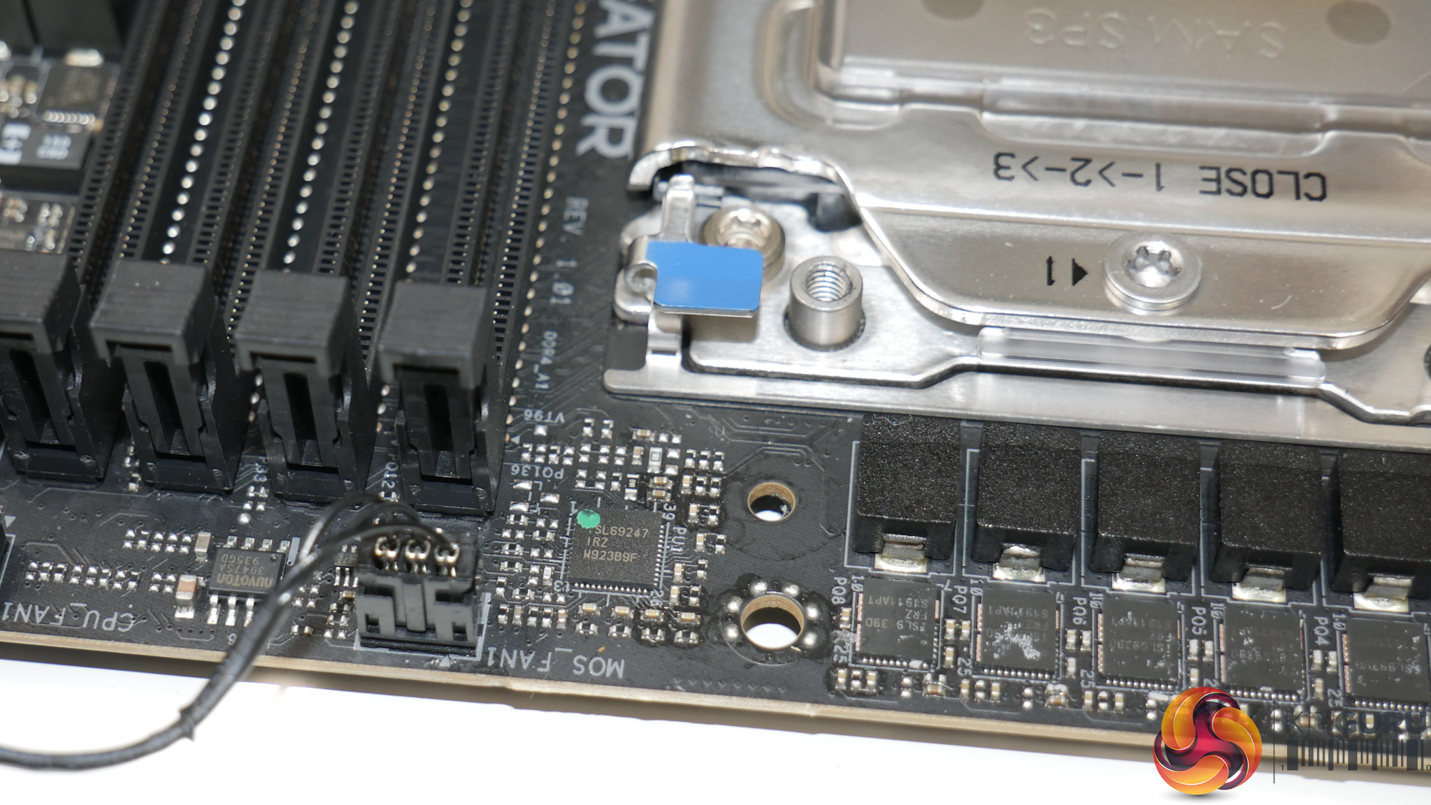
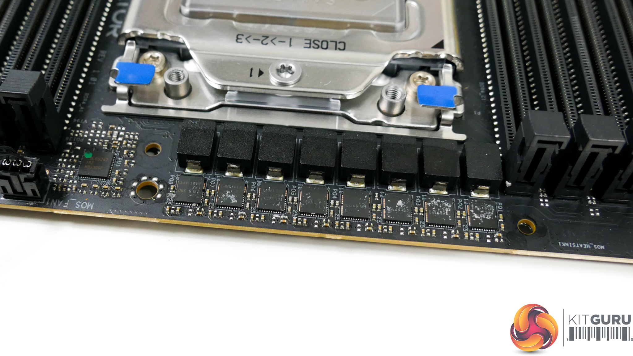
ASRock is using the Intersil ISL69247 PWM controller to manage the eight-phase power delivery system. There are no phase doublers present, implying that ASRock is running the PWM controller in 8+0 mode.
Intersil ISL99390 DrMOS power stages are used for direct power delivery. Each of these power stages features a current capability of 90A, giving the eight-phase VRM solution a theoretical peak of 720 Amps.
Despite the sprinkling of 12K-rated capacitors near the DIMM slots, the CPU area is notably slim of such components. Given the space constraints, ASRock is forced to mount the sizeable set of capacitors allocated to CPU duties on the motherboard’s rear side.
Even though some of the competing sub-£500 motherboards have a higher quantity of power delivery phases for their VRM solutions, it is hard to find criticism for an eight-phase system with 90A power stages. Even the 64-core 3990X is likely to be a manageable task for the TRX40 Creator’s power delivery capability, especially when combined with the active MOSFET heatsink.
Each of the two DRAM banks is fed by a two-phase power delivery system. Each set consists of one Intersil ISL69144 controller and two Vishay SiC632A integrated power stages.
The SoC is handled by an Intersil ISL69243 controller and two ISL99390 DrMOS power stages. This is a hefty power delivery system for the SoC and the components also feature direct cooling via a thermal pad connection to the left side of the VRM heatsink.
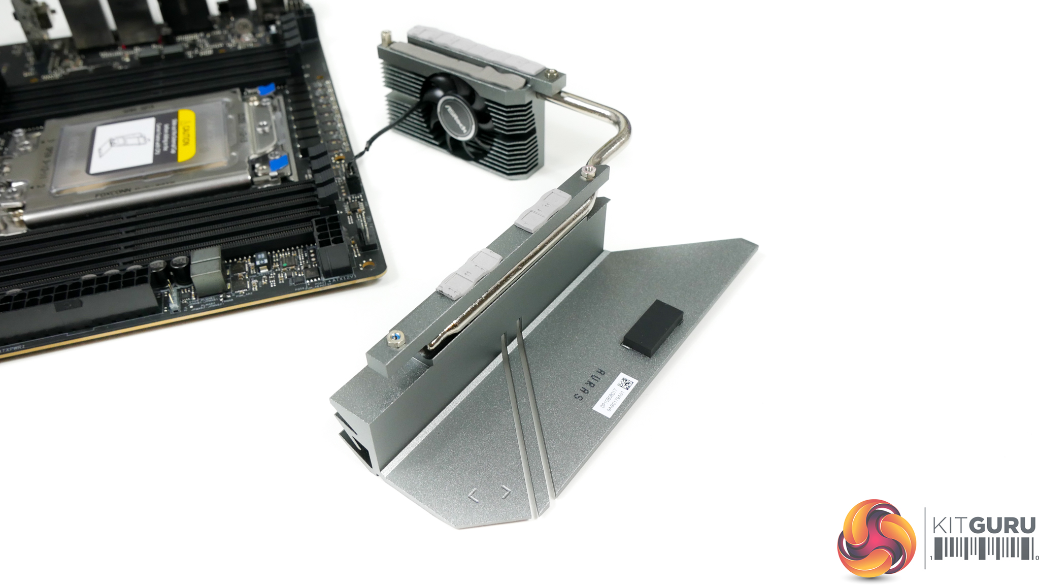
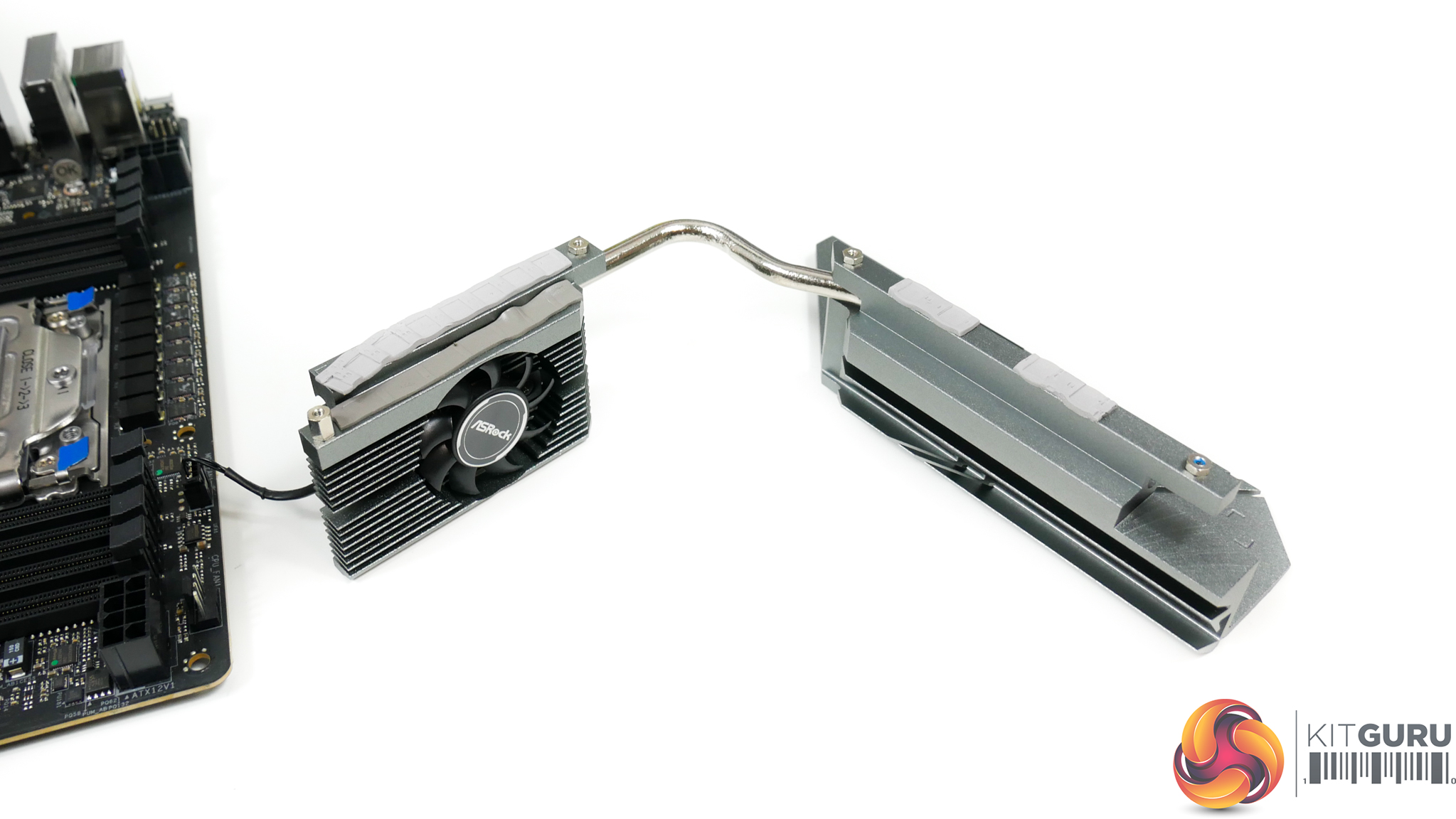
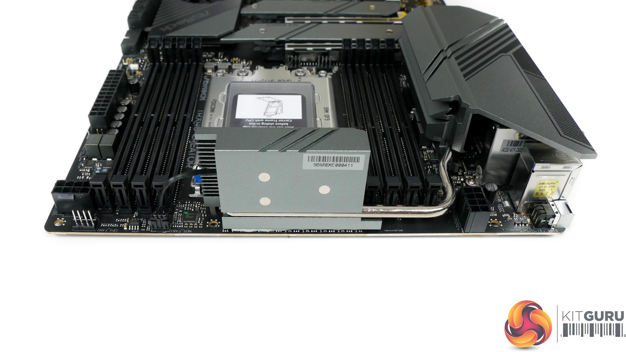
The approximately 37mm, up to 8800 RPM fan is positioned directly within the MOSFET section of the VRM heatsink. This makes sense as the underlying MOSFETs are the components that will shed the most energy into the heatsink. Thermal pad connections are made to the MOSFETs and also the low-profile chokes.
A single heatpipe is used to connect the VRM heatsink’s two individual fin stacks. While the smaller MOSFET section is clearly designed with surface area in mind, the larger secondary block of metal looks to place more focus on aesthetics. With that said, there’s plenty of benefit to the thermal capacitance of a solid slab of un-finned metal when it comes to dealing with short, intense loading periods.
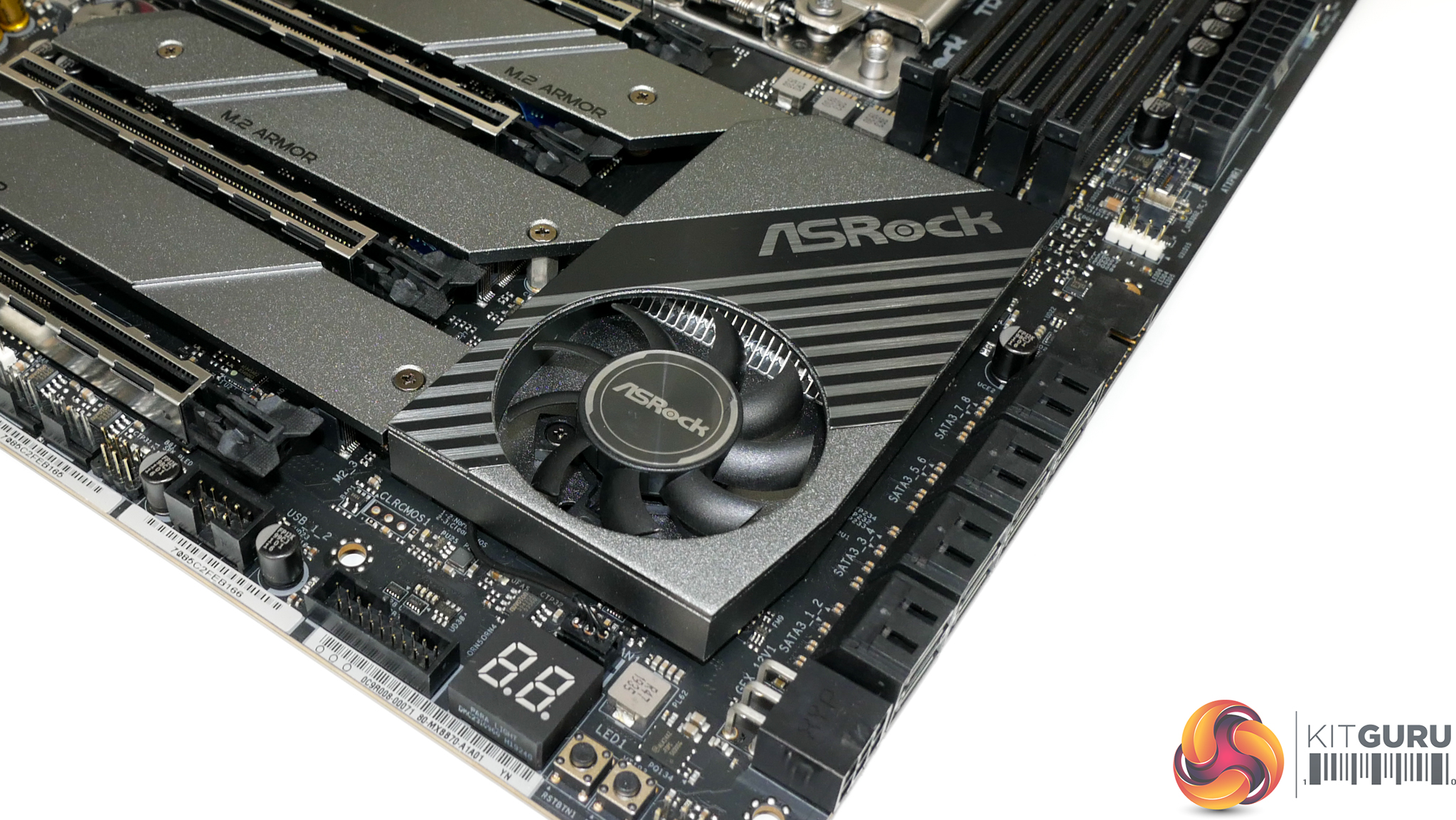
The chipset fan measures around 47mm diameter and can operate up to approximately 6900 RPM. This small blower is intended to direct air over a fin array that is rather generous in size for cooling the chipset.
Unfortunately, there is minimal consideration in the design for directing airflow towards the fin array. The positioning of the chipset fan is a challenge also, as an open venting graphics card sat in the slot above will exhaust its hot air into this small blower, thus raising chipset temperatures accordingly.
A temperature spike of more than 10°C was observed in our testing when a nearby GPU was loaded.