

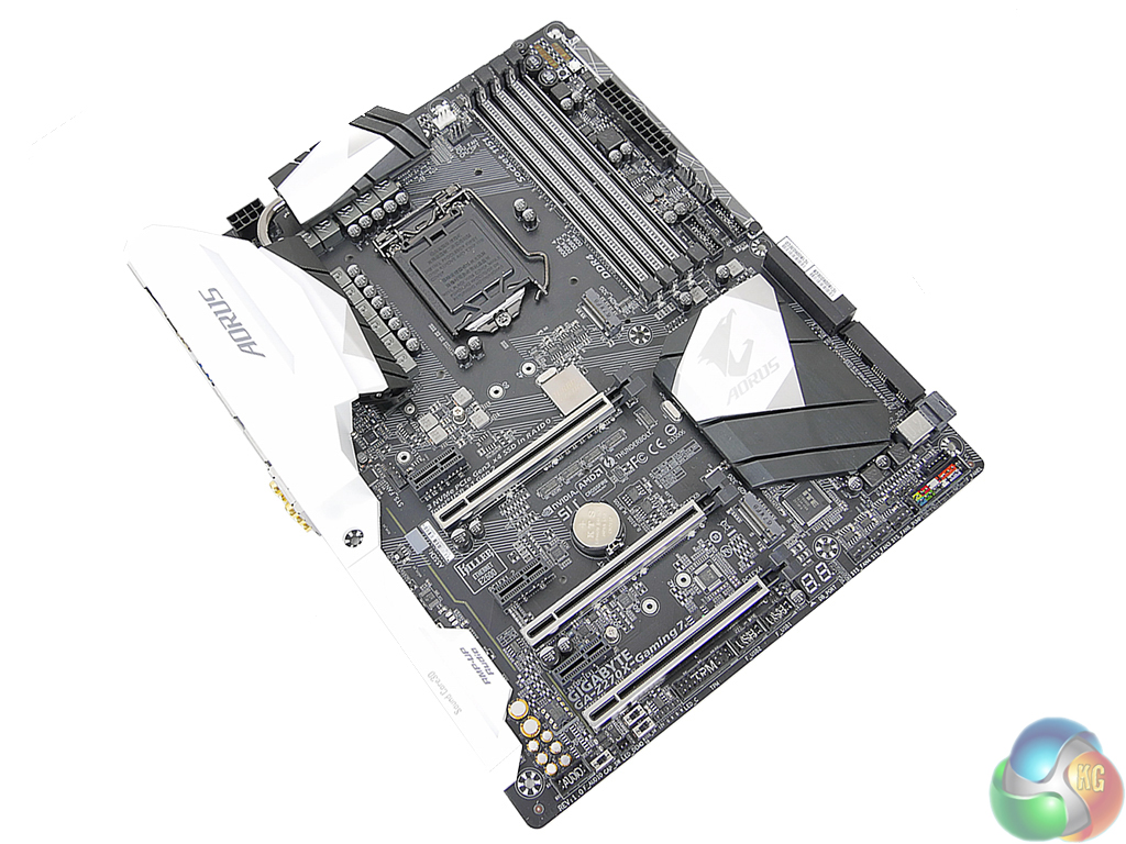
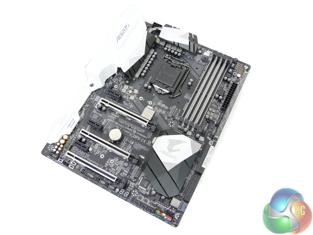
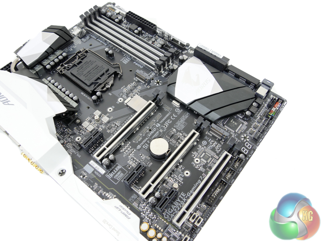
Gigabyte's Aorus Z270X-Gaming 7 is an ATX form factor motherboard. A black and white colour scheme is used superbly to create a very attractive motherboard (in my opinion).
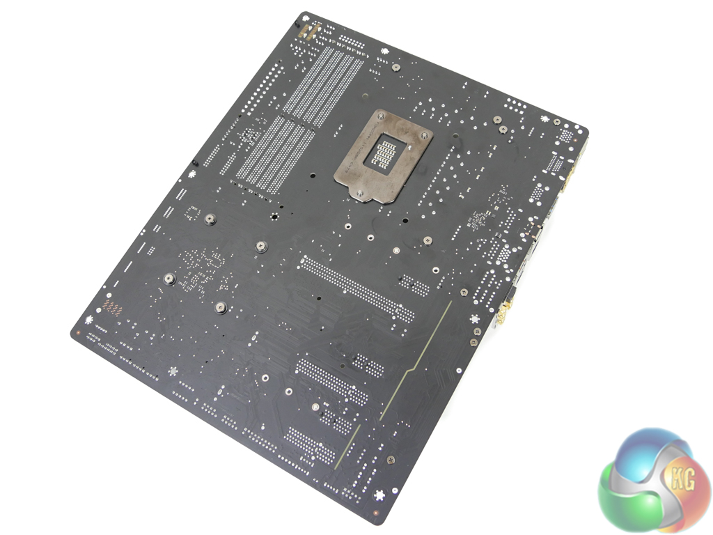
A glance at the motherboard's rear side gives a clear look at the PCIe lane distribution to onboard slots. No components of significance are mounted on the rear of the PCB.
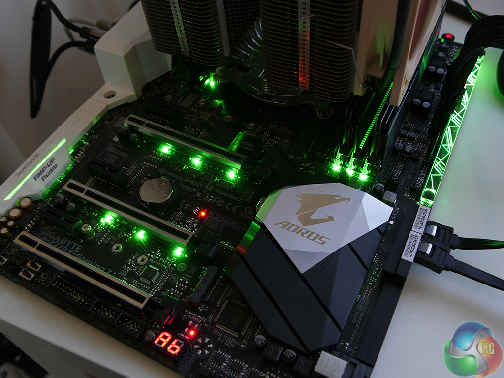
Seven individually-controllable RGB zones are found on the Z270X-Gaming 7, in addition to the external RGBW header. These zones are:
- Rear IO
- CPU VRM
- Audio section
- PCIe slots
- Chipset heatsink
- DIMM slots
- Right-hand plastic strip
The lighting solution for Gigabyte's board is superb. Brightness and colour accuracy are positives for the LEDs and the level of control is very good (as we will show later in this review). This solution is superior to that of ASRock's on the Fatal1ty Z270 Gaming K6 and ASUS' on the STRIX Z270F Gaming.
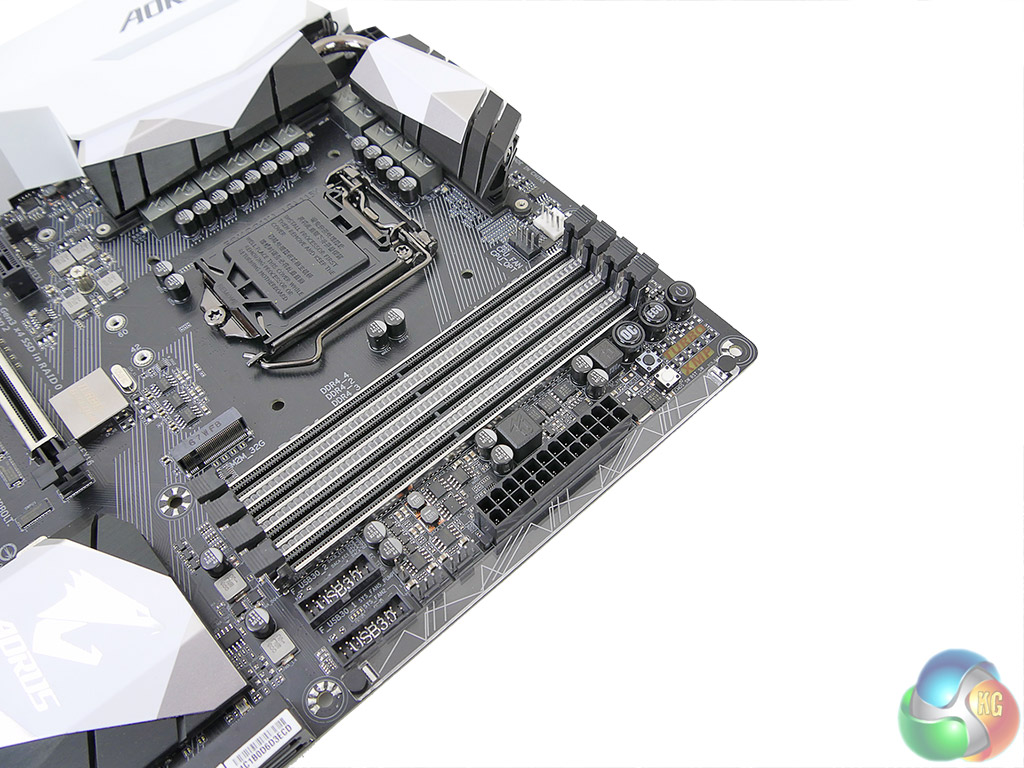
Four dual-latch DIMM slots provide support for up 64GB of dual-channel DDR4 memory (using currently available 16GB DIMMs). Gigabyte quotes memory frequency support of more than 4000MHz by way of overclocking but this will depend on CPU IMC strength and the BIOS stability. We are told that 3600MHz modules should work without issue on the motherboard while higher frequency DIMMs may cause slight issues with XMP tuning (if they are not on the QVL).
Gigabyte has a unique design to the DIMM slots. The steel reinforcement is good for minimising EMI and preventing PCB bending when initially pushing DDR4 modules into their slot. Three RGB LED strips occupy the space between the four DIMM slots which gives a superb glow originating from a location that is hidden when memory modules are installed.
Directly mounted on the motherboard's edge is a clear plastic strip that acts as a magnifier for RGB LEDs. The unique graphic printed onto the plastic strip creates an interesting appearance when the LEDs beneath are activated.
Also in this area is a pair of internal USB 3.0 headers provided using a Realtek RTS5411 USB 3.0 hub controller. Two 4-pin fan headers are found next door, one of which is also allocated pump duties. Above the 24-pin connector are onboard overclocking buttons. Power, reset, and clear CMOS are the usual trio but OC and Eco buttons are also added. Nearby are voltage monitoring that can prove useful for certifying the accuracy of software readings.
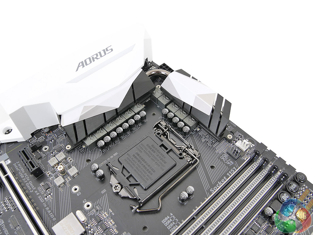
A total of 11 power delivery phases are used to drive voltage to the LGA 1151 CPU, its iGPU, and system rails. A well-designed heatsink is tasked with cooling the power delivery MOSFETs.
Intersil's ISL95866 hybrid digital PWM controller manages the power delivery system. The ISL95866 is an upgraded version of the 95856 thanks to its voltage offset adjustment and ability to control more rails. Four Intersil ISL6625A (marked 5AZ XXT) dual MOSFET drivers aid the PWM due to its inability to drive effectively a full eleven phases worth of MOSFETs.
Eleven pairs of Vishay PowerPAK SiRA12DP and SiRA18DP N-channel MOSFETs drive power to the components alongside ‘R50‘ marked chokes. The memory also uses Vishay MOSFETs and is managed by a Realtek RT8120D 2-phase PWM controller.
A Turbo BCLK IC helps to manage the CPU's operating frequency.
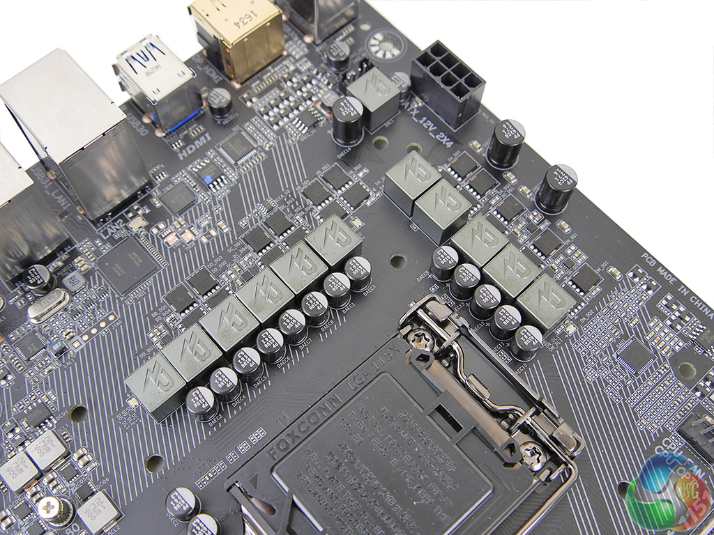
All six SATA 6Gbps connections originate from the Z270 chipset and can also combine to form three SATA-Express connections. Many people consider SATA-Express a dead connector but I personally still value it due to its ability to drive full-speed USB 3.1 Gen 2 front panel devices.
A 32Gbps PCIe 3.0 x4 U.2 connector is mounted next to the SATA ports. It is good to see the U.2 connector mounted natively rather than being supported via an M.2 adapter.
There is no problem created by the omission of an add-on SATA 6Gbps chipset to provide two more ports. This is thanks to Gigabyte's smart distribution of chipset IO lanes than means only two SATA 6Gbps ports are disabled when the upper M.2 slot is taking a PCIe or SATA SSD. The bottom slot does not disable SATA ports other than one that will be used if an M.2 SATA SSD is installed.
Gigabyte smartly designs the PCIe lane allocation so that interference between U.2 and SATA does not occur (in terms of disabling other features).
Two M.2 ports found on the motherboard both support PCIe 3.0 x4 NVMe operation as well as SATA 6Gbps mode. The upper slot can take 110mm-long SSDs whereas the lower is limited to 80mm in length.
Bandwidth from the upper slot is partially shared with SATA 6Gbps ports. Install a SATA/PCIe x2/PCIe x4 SSD into the upper M.2 slot and SATA ports 4 and 5 will both be disabled.
The lower M.2 slot only steals one SATA port 0 if a SATA SSD is installed there. Use a PCIe SSD and the SATA ports are unaltered but the PCIe 3.0 x4 physical slot drops to PCIe 3.0 x2 bandwidth.
Put simply, you should use the lower M.2 connector first, provided you have nothing to go in the lower PCIe full-length slot. The caveat here, as our testing in this review will show, is that an M.2 SSD in the lower slot is more susceptible to thermal throttling as it is further away from airflow created by the CPU cooler and graphics card. While this primarily depends on your individual system configuration, it is disappointing that Gigabyte has not provided any form of M.2 cooling solution that competing vendors such as MSI and ASUS offer.
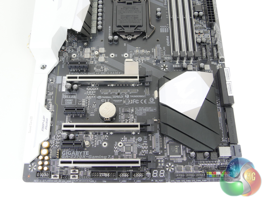
Gigabyte uses steel-reinforced PCIe slots to improve the strength of all three full-length slots. This helps to limit PCB sag for GPUs and also minimises the risk of slot breakage when shipping a system with a heavy graphics card installed.
The full-length PCIe slot electrical wiring is PCIe 3.0 x16, x8, and x4. With two graphics cards installed, the upper two slots will run at x8/x8 using CPU-fed lanes. The bottom full-length PCIe slot receives four lanes from the Z270 chipset but it is forced to share them with the lower M.2 slot (it will drop to PCIe 3.0 x2 with an M.2 SSD installed there). This means that three expansion cards are supported at x8 CPU/x8 CPU/x4 chipset, which is ideal for running two high-end GPUs and a PCIe SSD.
Spacing of the full-length slots is ideal. Clearance between the uppermost connector and CPU socket paves the way for large air coolers, while a two-slot gap between the first and second x16 slots gives dual-width graphics cards a cooling gap.
All three PCIe x1 slots use Gen 3 lanes originating from the Z270 chipset. The third slot shares its bandwidth with a SATA port meaning that only one of those can be used at a given time.
Going back to the point on lane distribution, Gigabyte is keen to point out that triple PCIe 3.0 x4 SSDs can be used simultaneously on the Z270X-Gaming 7. The upper M.2 slot, U.2 connector, and lower PCIe x4 slot or M.2 connector do not interfere with each other's bandwidth making them all functional simultaneously. This is ideal for users who want to RAID 0 three Intel 750 SSDs through the chipset without stealing the CPU's PCIe lanes.
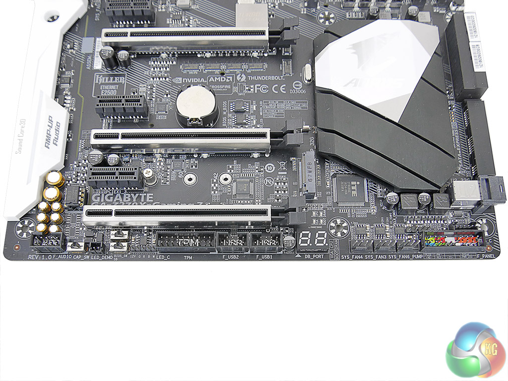
Two USB 2.0 headers sit next to a 2-digit debug LED display that I love to see included. Two BIOS switches allow for switching between the main and backup BIOS as well as single or dual BIOS mode operation. Another switch moves the audio gain between 2.5x and 6x for the rear panel headphone/speaker output jack.
For RGB LED strip control, Gigabyte opts for a 5-pin header rather than the usual 4-pin alternative by adding a white pin. Importantly, the pins are re-mappable in software which allows the Z270X-Gaming 7 to support a wide variety of RGB LED strips by simply re-programming the pin location to suit the strip. This is a smart way of dealing with the fragmented LED strip market.
Three system fan headers reside next to the front panel connection block.
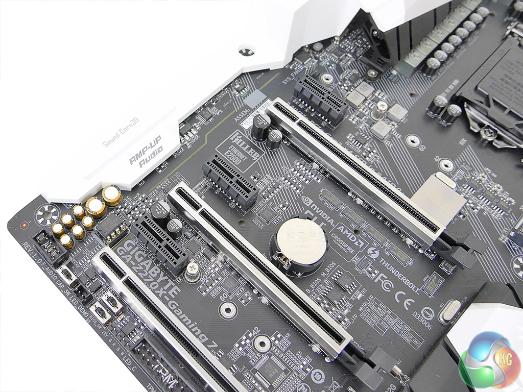
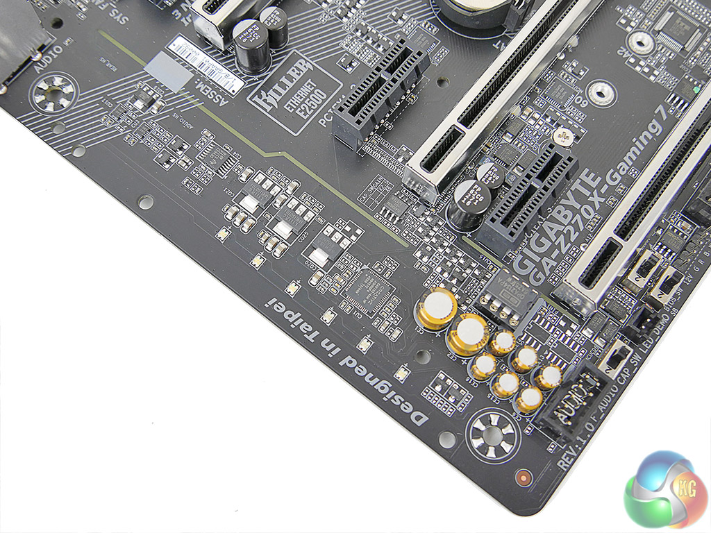
Hidden beneath the plastic shroud is a quad-core Creative Sound Core3D CA0132 chip. Partnering the Creative chip are a Texas Instruments DRV632 audio line driver with adjustable gain and a Burr Brown OPA2134 operational amplifier from the same vendor. Additional hardware includes Nichicon Fine Gold audio capacitors and a ASM393M comparator.
Creative software tools such as the SBX Pro Studio Suite, Scout Mode and VoiceFX are also supported. The Burr Brown operational amplifier is user upgradeable allowing audiophiles with specific preferences to adjust the system to their own personal requirements.
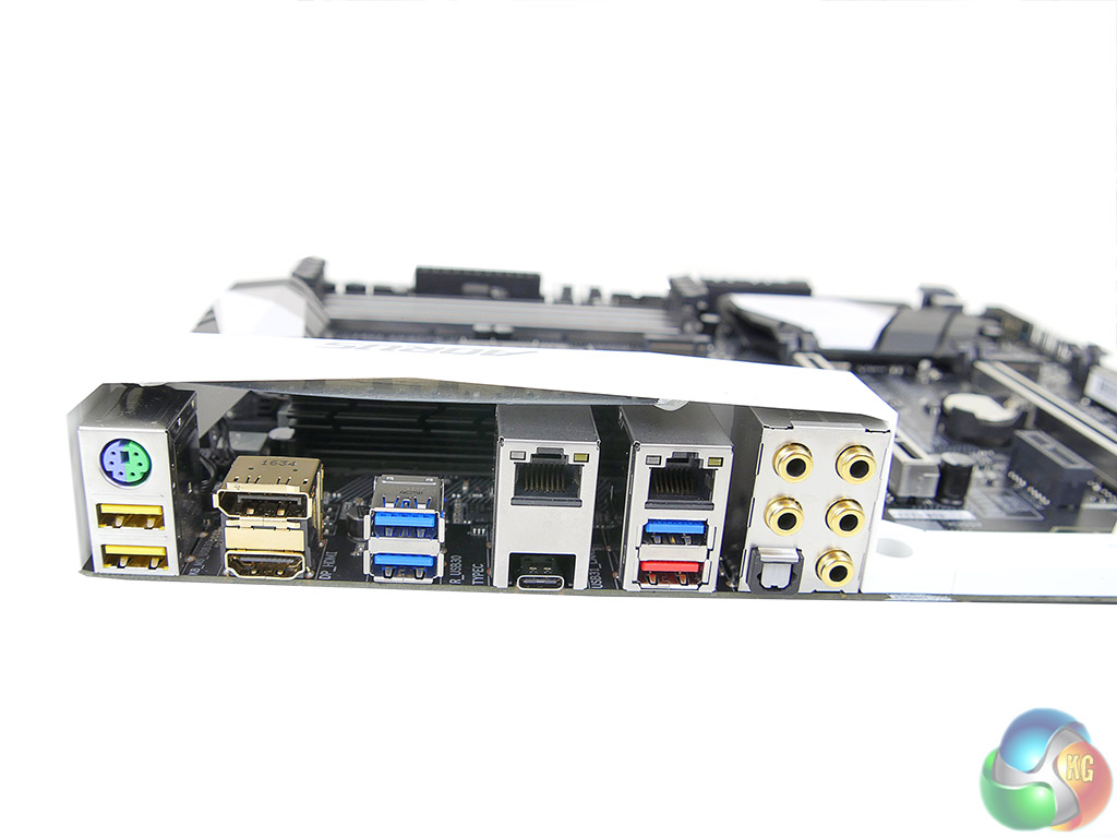
10Gbps USB 3.1 and 40Gbps Thunderbolt 3 connectivity is provided through the single Type-C connector. Intel's PCIe 3.0 x4 JHL6540 controller is used to provide Thunderbolt 3 and USB 3.1 connectivity (aided by a Texas Instruments TPS65982 switch for USB Type-C functionality and Power Delivery 2.0 operation). A red-coloured Type-A ports also features 10Gbps USB 3.1 Gen 2 capability.
The four-lane Thunderbolt 3/USB 3.1 Gen 2 controller has 32Gbps of total bandwidth which is double that of the ASMedia ASM2142 alternative used by competing board vendors. With that said, both solutions provide ample bandwidth for a single high-speed USB 3.1 Gen 2 device, though Intel's controller may show improvements if a pair of high-speed USB 3.1 SSDs is used simultaneously.
In addition to three standard 5Gbps USB 3.0 ports, two yellow-coloured DAC-UP 2 ports feature a dedicated power design to deliver cleaner signals which is important for USB audio devices. A few more Type-A USB ports would have been welcomed as five (excluding the 3.1 Gen 2 port) is likely to be filled quickly.
The gold-plated HDMI port is version 1.4, meaning that it is not capable of 4K60 output. The DisplayPort 1.2 output will do 4K60, though. Dual GbE NICs are provided by means of an Intel I219V chipset and Killer's E2500 series solution. These ports cannot be teamed together for double the bandwidth but they can be used for redundancy or compatibility reasons. I'd have preferred a pair from the same vendor for teaming support, to be honest.
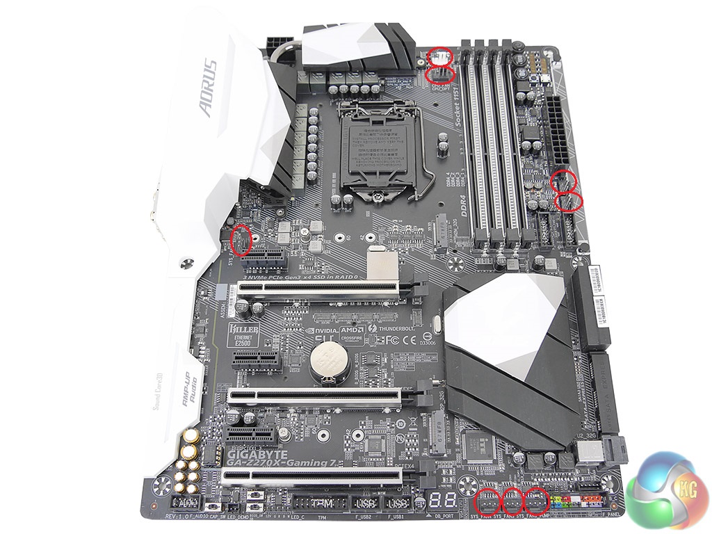
Gigabyte has made impressive strides with its fan header system found on the Aorus Z270X-Gaming 7. A total of eight (!) 4-pin Hybrid headers are smartly distributed around the board. Two are positioned and labelled for CPU duties.
Every one of the headers can detect whether to operate in PWM or DC mode and the 2A power delivery allows them to power a watercooling pump at full speed. We noticed the motherboard managing speeds of our 3-pin fans on the Noctua NH-D14 without any user input, which is impressive to see. If you want a lesson on how to implement fan connectivity options on a high-end motherboard, this is it.
Management of the fan and system monitoring duties is handled by ITE IT8686E and IT8792E chipsets.
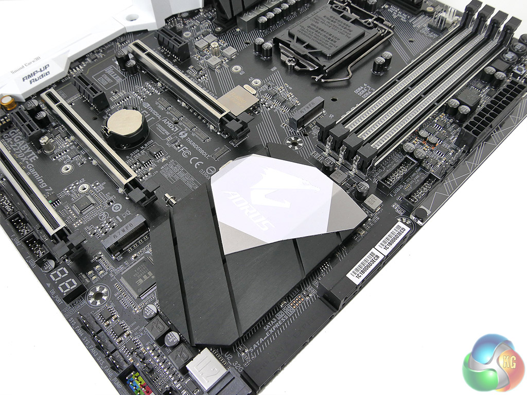
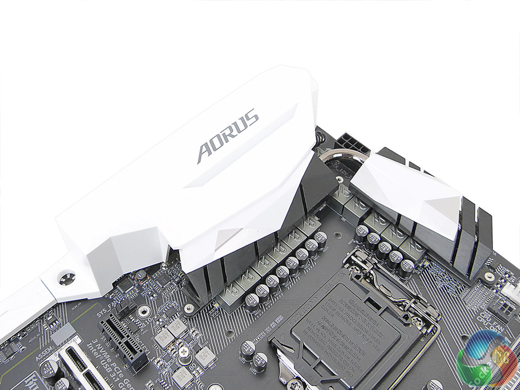
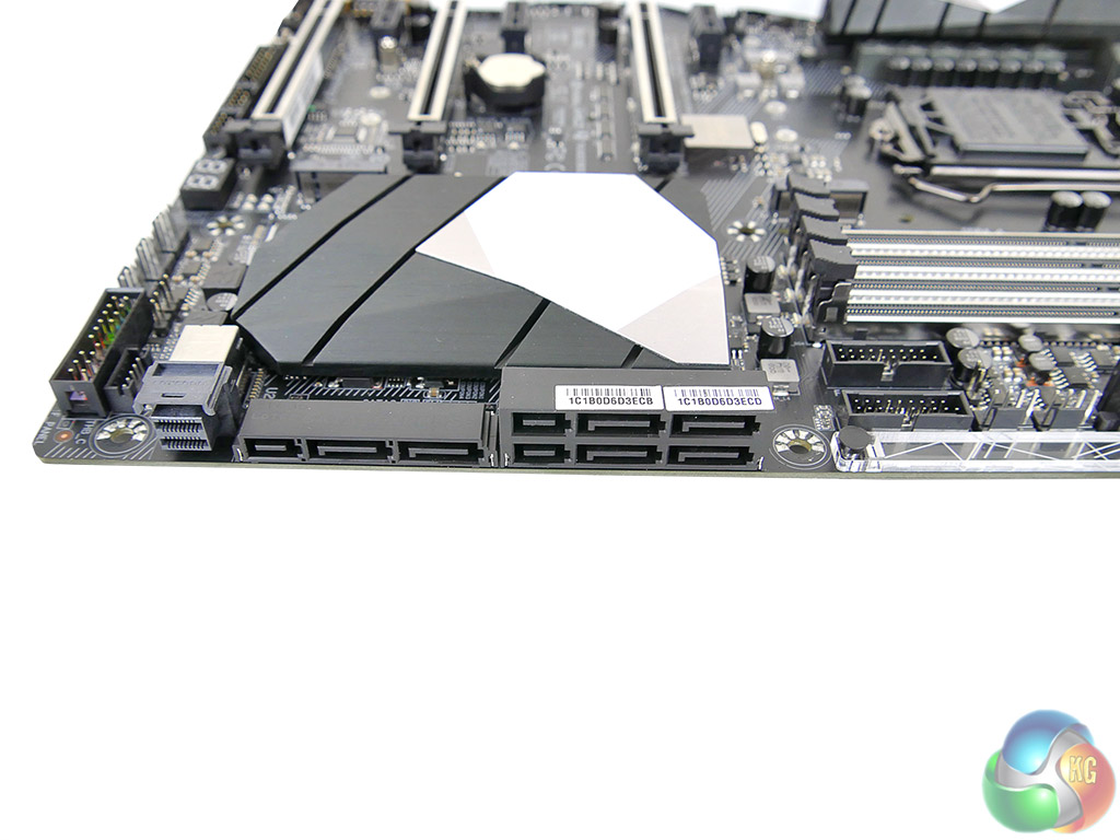
Attractive and functional white and black heatsinks are used for the Aorus Z270X-Gaming 7.

“The individual audio results should be interpreted with care due to the difference in RightMark Audio Analyzer’s reaction to the Creative-based solution used on Gigabyte’s board versus the Realtek codec of its competitors.”
I don’t understand what that means.
I have this board and while it’s a tremendously beautiful work of art, RGB Fusion doesn’t hold its brightness settings after reboot. Which, can be annoying when the PC is on your desk just to your right and you don’t want those beautiful bright greens to be /too/ bright, so you tone them down to the lowest setting (25%) only to find that you have to do it every single time you boot into Windows 10 Pro x64. I looked to see if there were any obvious files in the RGB Fusion folder that would hold settings for such and if they perhaps were read-only, but the only settings files I found were xml’s for various demo effects, I would assume. I’ve tried setting the main exe’s in the folder to run as administrator and see if that works. No dice. Seems as if Gigabyte might have a little more work left to do with this, and funny enough, their GvLedServices.exe file descriptions weren’t filled out. They were left as “TODO: ” .. “TODO: ” .. “TODO: ” under Properties > Details. I guess that slipped their “to do” list. It shows up as “TODO: ” in Task Manager > Processes, which could potentially confuse someone that isn’t privy to the program not quite being as polished as it should be.
Also, I had an issue where, suddenly, when trying to run the RGB Fusion program, it would load the dialog box, but that’s it, and sit there with blank panels and “Please Wait…” flashing through the RGB spectrum in the middle of the main panel for around 5 minutes before finally loading, then making any changes would take another few minutes or so, but they wouldn’t actually do anything. The power switch at the top no longer turned the LED’s off, either. I had to uninstall the program, reboot, reinstall the program and then run each process from its folder manually to get it to work again. It’s been working since then, even after reboots, but still doesn’t hold the brightness setting.
https://uploads.disquscdn.com/images/7bd0e4c346835a42abdf525b89866c38c628c6205a00e90bada27f21db0bbf2f.jpg
Might as well be written in another language and then translated back to English with Google translator.