

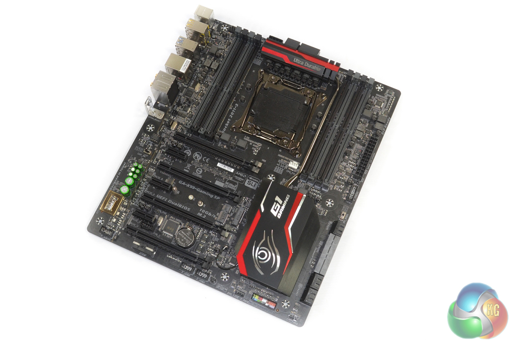
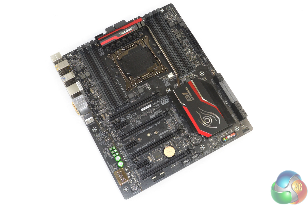
Gigabyte outfits the X99-Gaming 5P in the red and black scheme the company uses for its Gaming series components. Red touches on the heatsink contrast a largely black appearance.
There are also red LEDs in the chipset heatsink and audio PCB traces.
The motherboard conforms to the EATX form factor, meaning that you will need a wider than standard case to house the board. While many full tower cases will accommodate EATX motherboards with ease, there are some mid-tower cases, such as the NZXT H440, which only officially support ATX boards.
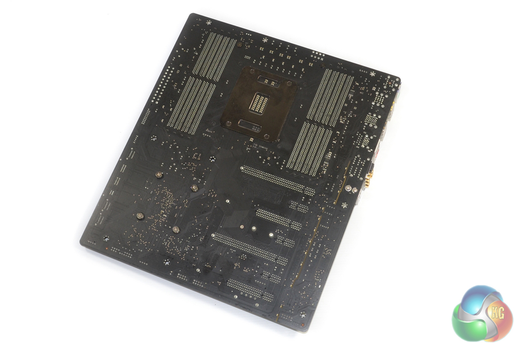
A look at the rear of the PCB shows that Gigabyte is using an all-black matte finish.
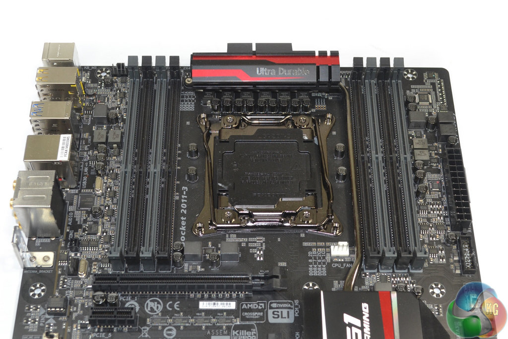
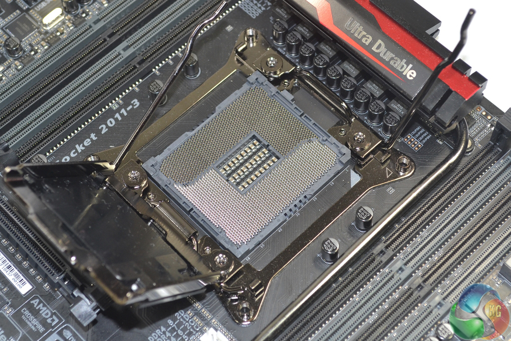
LGA 2011-3 CPUs can be installed in the socket. Gigabyte adds extra pins to the socket (much like Asus pioneered with the vendor’s OC Socket) in order to unlock enhanced overclocking options and capacity.
Up to 128GB of DDR4 memory can be installed in the eight single-latch DIMM slots. Gigabyte outlines supported frequencies of up to 3333MHz.
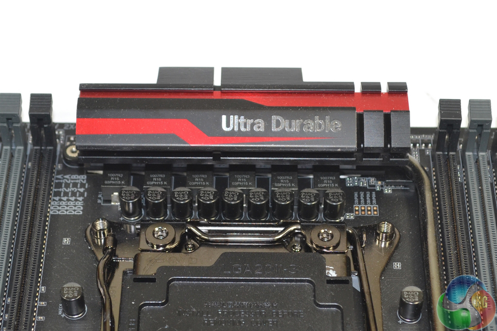
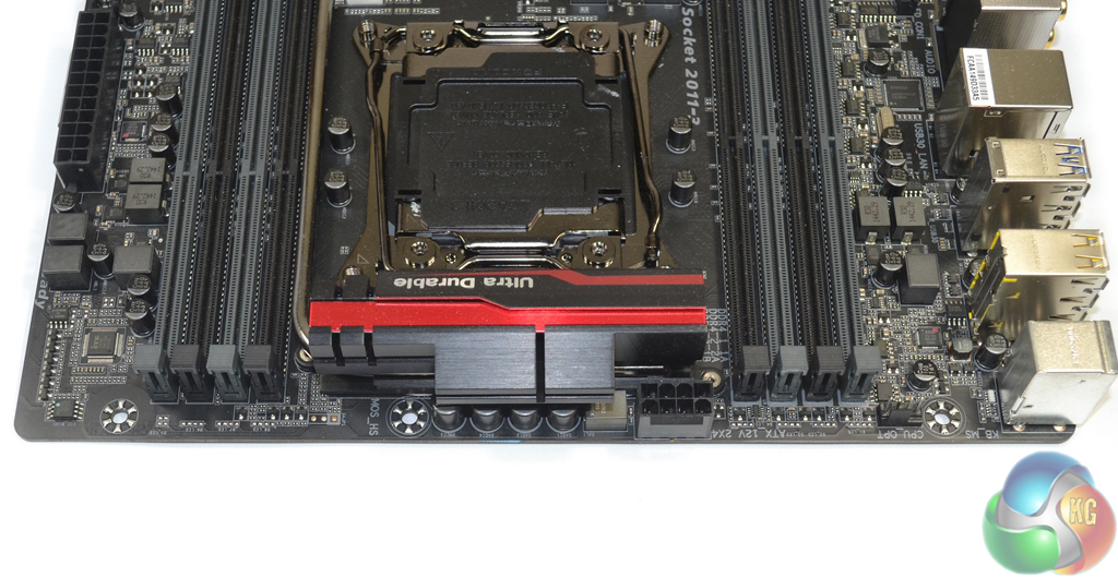
A six-phase power delivery system feeds the LGA 2011-3 CPU. Gigabyte cools the MOSFETs by way of a sturdy metal heatsink that is connected via heatpipe to the sizable chipset heatsink.
The MOSFETs used are six International Rectifiers IR3556M PowIRstage solutions which are managed by the same company’s IR3580 PWM controller. All six chokes are marked ‘1007R3 R15 03PH15 K’.
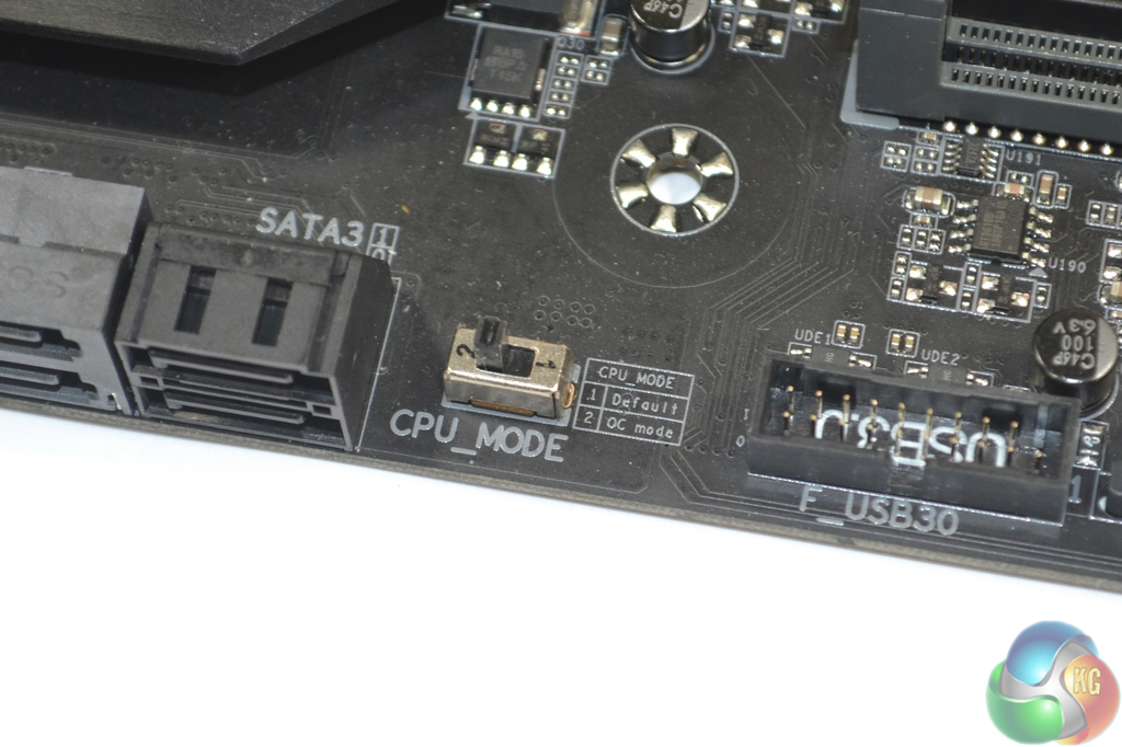
A toggle switch is used to activate the extra pins in the CPU’s socket.
This gives users the flexibility to choose which socket implementation design guidelines they want to use, although I do not see any negatives to using the additional pins, excluding potential warranty issues that were reported at X99’s launch.
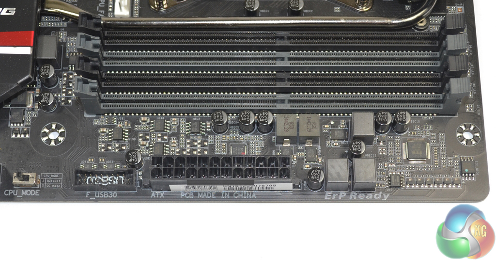
Adjacent to the 24-pin power connector is the vertical-facing USB 3.0 header.
A cluster of electronic components in this area feeds the right-side DIMM bank as well as some of the system voltages.
Highlights of the memory power delivery section are an International Rectifiers IR3570A PWM controller and IR3553M power solution for each DIMM bank.
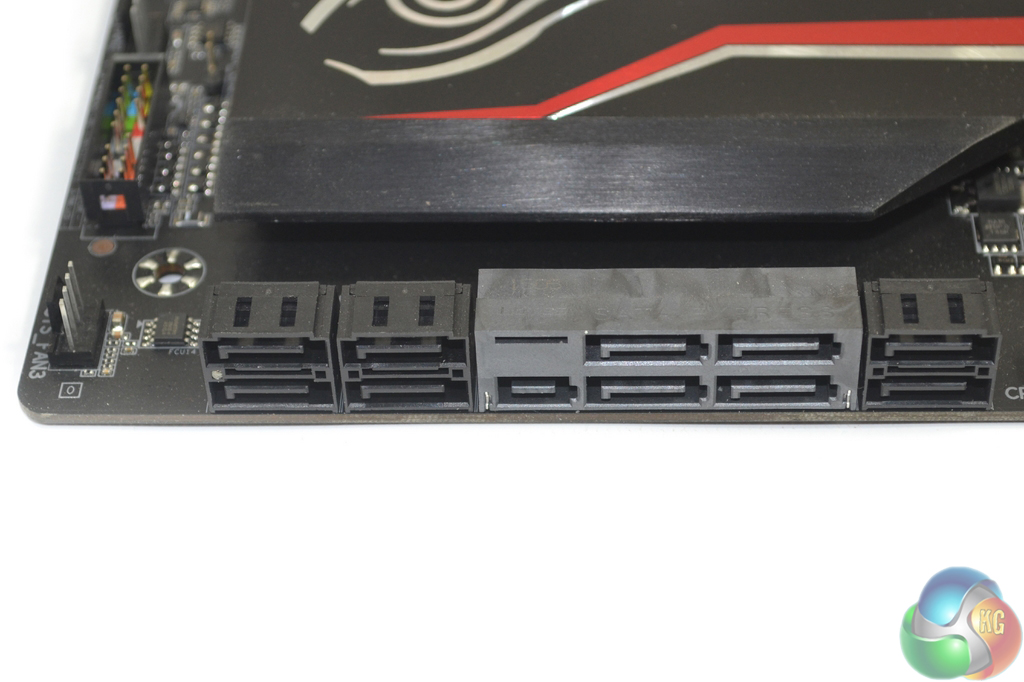
All ten SATA 6Gbps ports are provided by the X99 chipset. Two of the ports double up as the board’s 10Gbps SATA-Express connector.
Using the SATA-Express connector renders the motherboard’s M.2 connector unusable.
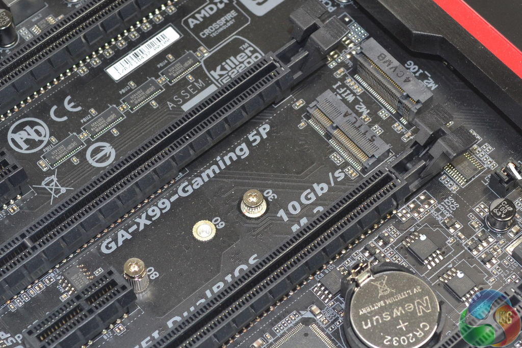
Gigabyte equips the X99-Gaming 5P with two M.2 connectors, although only one of them can be used for storage. The other M.2 port is intended for use with WiFi adapter cards.
The storage-fed M.2 connector only operates at 10Gbps via two PCIe 2.0 lanes from the chipset. Really, Gigabyte? The 10Gbps M.2 idea has been and gone for X99 motherboards. 10Gbps is simply inadequate for many currently available and upcoming M.2 SSDs (Samsung’s XP941 and SM951, for example).
This really squeezes the storage choices for a potential buyer. Yes, there is the backup option of simply going with a PCIe-to-M.2 adapter card, but that limits the use of PCIe slots for other devices.
Gigabyte has clearly ignored the vast amount of feedback that it received from a variety of sources regarding a 10Gbps transfer rate for the M.2 slot. And there’s simply no excuse for it, especially given that this motherboard released well after the X99 platform’s inception in August of 2014.
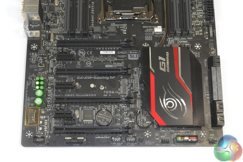
Up to 4-card SLI and CrossFire is supported by a 40-lane CPU. The supported lane configurations for a 40-lane chip are: x16/x0/x0/x0, x16/x0/x16/x0, x16/x0/x16/x8, and x8/x8/x16/x8.
A 28-lane chip limits the maximum number of cards supported in SLI to a trio. CrossFire can still run in 4-way thanks to its application with a 4-lane PCIe link.
Gigabyte’s PCIe slot layout is about as good as it gets for an X99 motherboard. There is a two-slot cooling gap between a pair of boards and three cards also line-up in preferable spacing arrangements.
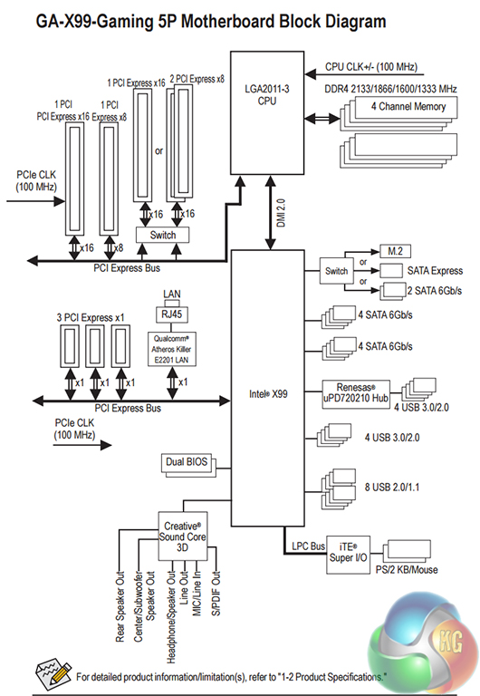
Gigabyte’s inclusion of a block diagram in the user manual is excellent for users with complex requirements.
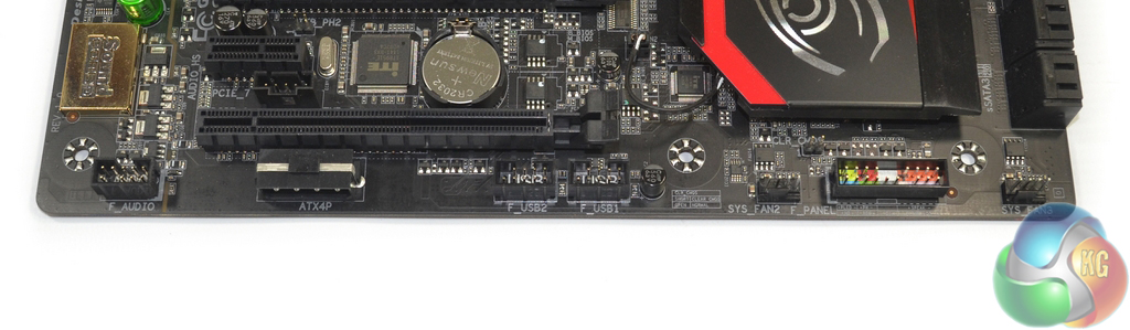
The standard affair of front panel connectors is present. Gigabyte also adds a downwards-facing 4-pin molex power port to provide additional juice for heavy multi-GPU configurations.
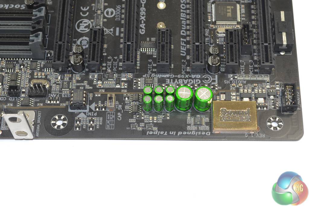
At the heart of the audio solution is a Creative Sound Core 3D quad core processor. Accompanying the particularly high-end audio chip are Nichicon MUSE capacitors, a Burr Brown OPA2134A upgradeable operational amplifier, and a Texas Instruments DRV632 amplifier.
The audio signals are transferred along segregated PCB tracks and EMI shielding is placed over the Creative processor. Gigabyte also includes a switch that allows users to boost the audio system’s gain. This can be useful for driving differing audio setups.
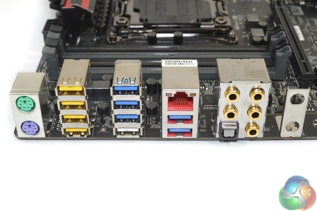
Plenty of USB 2.0 and 3.0 ports are found on the motherboard’s rear IO, however there is a distinct lack of USB 3.1. This is related to Gigabyte’s preference of add-on chipset supplier and the primary USB 3.1 controller that is getting widespread use being from ASMedia (a company with ties to Asus). VIA now has a USB 3.1 solution on the market, so I would expect Gigabyte’s USB 3.1 boards to show up in coming months.
Each of the DAC-UP USB 2.0 ports receives direct power to deliver a clean signal to USB DACs.
Killer’s E2201 NIC is used for Gigabit Ethernet. One of the main reasons for choosing a Killer NIC is the board vendor’s ability to provide users with Killer’s Network Manager software that allows network control.
Motherboard rear ports:
- 1 x PS/2 keyboard port
- 1 x PS/2 mouse port
- 6 x USB 3.0 ports (X99 chipset and Renesas D720210 one-to-four-port hub)
- 4 x USB 2.0 ports
- 1 x optical S/PDIF Out connector
- 1 x RJ-45 port (Killer E2201)
- 5 x audio jacks (Center/Subwoofer Speaker Out, Rear Speaker Out, Line In/Mic In, Line Out, Headphone)
- 2 x Wi-Fi antenna connector holes
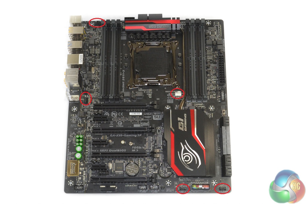
Five fan headers are spread smartly around the board, four of which are within reach of the CPU socket. Placing two along the bottom edge is a smart move that makes it easier to route connections for front or side panel chassis fans.
Monitoring capacity is provided by ITE’s IT8620E chipset. Further ITE chipsets (2x IT8792E and IT8951E) provide various functionalities for the motherboard. Dual BIOS chips are used for redundancy.
Reset your job with kitguru…. –_______ Continue Reading
Your Mind is Butter ..by kitguru… Find Here
How to do work with kitguru … Keep Reading