
The Corsair SF450 Platinum offers higher efficiency than its Gold predecessor and it is also bundled with a SFX-to-ATX bracket. The question we will answer today is should you pay more to get the Platinum model or is it better to save some money and go for the Gold model instead?’
Corsair wants to turn things around in the SFX form factor category with new SF Platinum units which are sold in 450W and 600W capacities with a 750W model on the way. We have already evaluated the SF600 Platinum which left a very good impression on us and the time has come for the SF450 Platinum to be laid bare in our test labs.
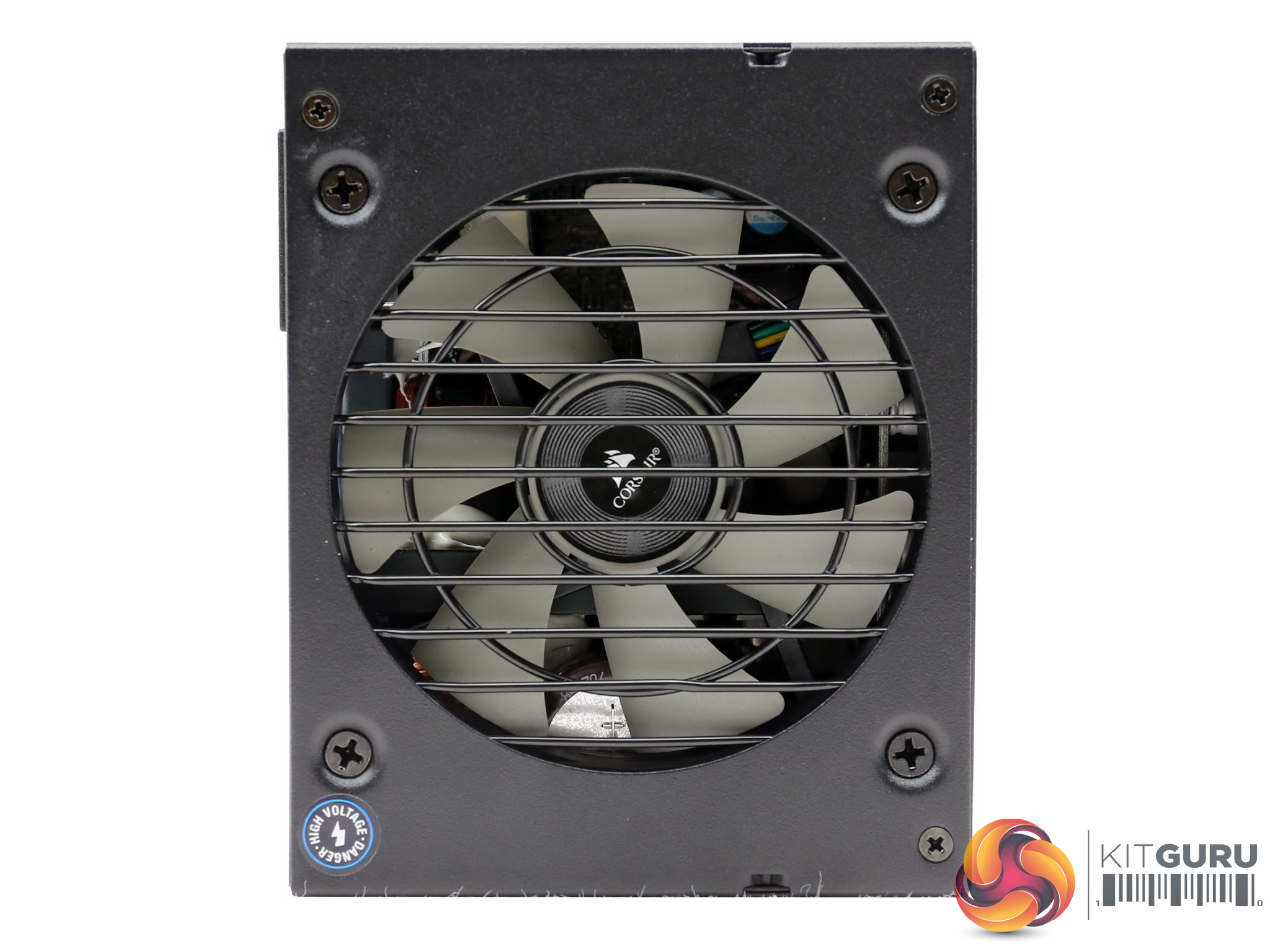
The Corsair SF450 Platinum shares the same cable configuration with the 600W model which is unusual, as the larger wattage models are normally equipped with additional cables and connectors. Both units are fully modular of course. They are cooled down by fans measuring 92mm in diameter – the largest that an SFX unit can accommodate. By using the largest possible fan, Corsair promises to bring the noise output down even under tough conditions. A quality 92mm fan is able to provide the same airflow as a 80mm fan but at lower speeds – which means less noise emissions.
The most important difference with the previous Gold SF line (which will remain in production), is the efficiency increase which was upgraded from 80 PLUS Gold to 80 PLUS Platinum. In the Cybenetics database both lines fall into the ETA-A efficiency category, however there are notable differences in the noise output, mostly for the 600W SF models.
Obviously the higher efficiency allows for a more relaxed fan profile. In the majority of cases SFX power supplies are noisier compared to ATX models, because of the overpopulated PCBs which don't allow for optimal airflow. Nonetheless, lately the major brands and manufacturers have worked hard to offer lower noise operation in compact platforms as well.
Given the increased interest of all major brands in this category lately, we are curious to see the first passive SFX unit to hit the market, especially since a while ago we had the chance to evaluate the first passive SFX-L model, the SilverStone Nightjar NJ450-SXL.
Read our How We Test Power Supplies HERE
Specifications
| Manufacturer (OEM) | Great Wall |
| Max. DC Output | 450W |
| Efficiency | 80 PLUS Platinum, ETA-A (88-91%) |
| Noise | LAMBDA-A (20-25 dB[A]) |
| Modular | ✓ (Fully) |
| Intel C6/C7 Power State Support | ✓ |
| Operating Temperature (Continuous Full Load) | 0 – 50°C |
| Over Voltage Protection | ✓ |
| Under Voltage Protection | ✓ |
| Over Power Protection | ✓ |
| Over Current (+12V) Protection | ✓ |
| Over Temperature Protection | ✓ |
| Short Circuit Protection | ✓ |
| Surge Protection | ✓ |
| Inrush Current Protection | ✓ |
| Fan Failure Protection | ✗ |
| No Load Operation | ✓ |
| Cooling | 92mm Rifle Bearing Fan (NR092L) |
| Semi-Passive Operation | ✓ (non selectable) |
| Dimensions (W x H x D) | 127x 65 x 103mm |
| Weight | 0.86 kg (1.9 lb) |
| Form Factor | SFX, EPS 2.92 |
| Warranty | 7 Years |
Corsair has strengthened its ties with OEM partner Great Wall in the last couple of years and this is welcomed, because due to this tight cooperation the performance bar in the SFX category has reached new levels – which a while ago seemed impossible for such small designs.
All popular protection features are present and the 92mm rifle bearing fan is supported by a semi-passive mode, which unfortunately cannot be deactivated. This means that you should not install this unit with its fan facing downwards as you will trap the hot air internally and this will put quite a strain on the platform's sensitive components (e.g. the electrolytic caps).
The compact dimensions classify this product in the SFX form factor, while it also meets the EPS 2.92 specification requirements. Finally, the provided warranty is seven years.
Power Specifications
| Rail | 3.3V | 5V | 12V | 5VSB | -12V | |
| Max. Power | Amps | 15 | 20 | 37.5 | 2.5 | 0.3 |
| Watts | 100 | 450 | 12.5 | 3.6 | ||
| Total Max. Power (W) | 450 | |||||
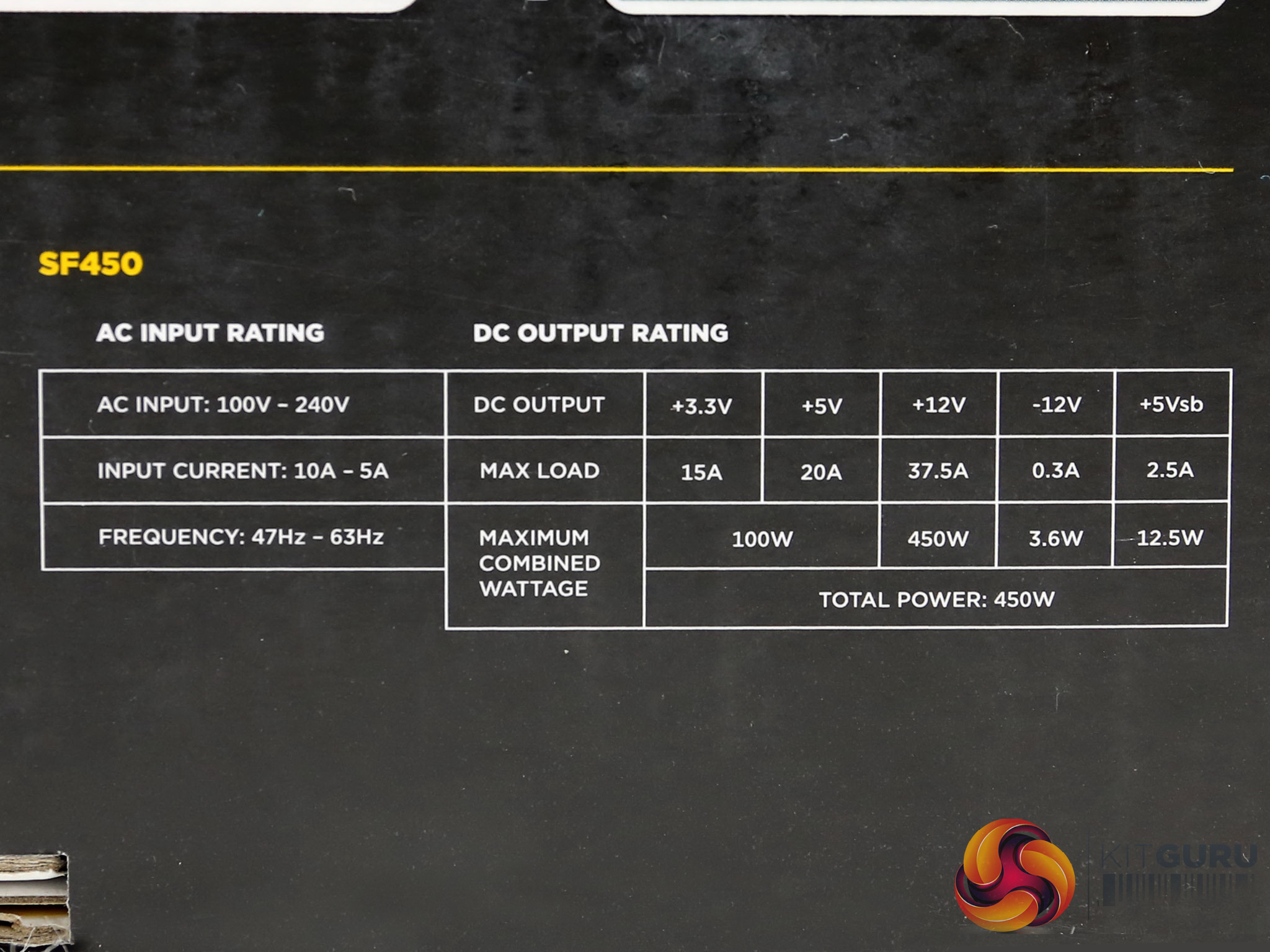
The minor rails have 100W max combined power, which is more than enough for any normal modern system. The +12V rail typically can deliver the unit's full power alone and the 5VSB rail has 2.5 Amps max current output.
Cables & Connectors
| Modular Cables | ||||
| Description | Cable Count | Connector Count (Total) | Gauge | In Cable Capacitors |
|---|---|---|---|---|
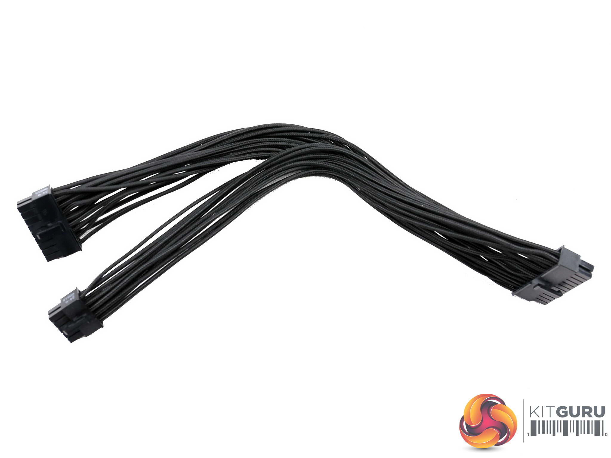
| ATX connector 20+4 pin (300mm) | 1 | 1 | 16-18AWG | No |
| 4+4 pin EPS12V (400mm) | 1 | 1 | 16AWG | No |
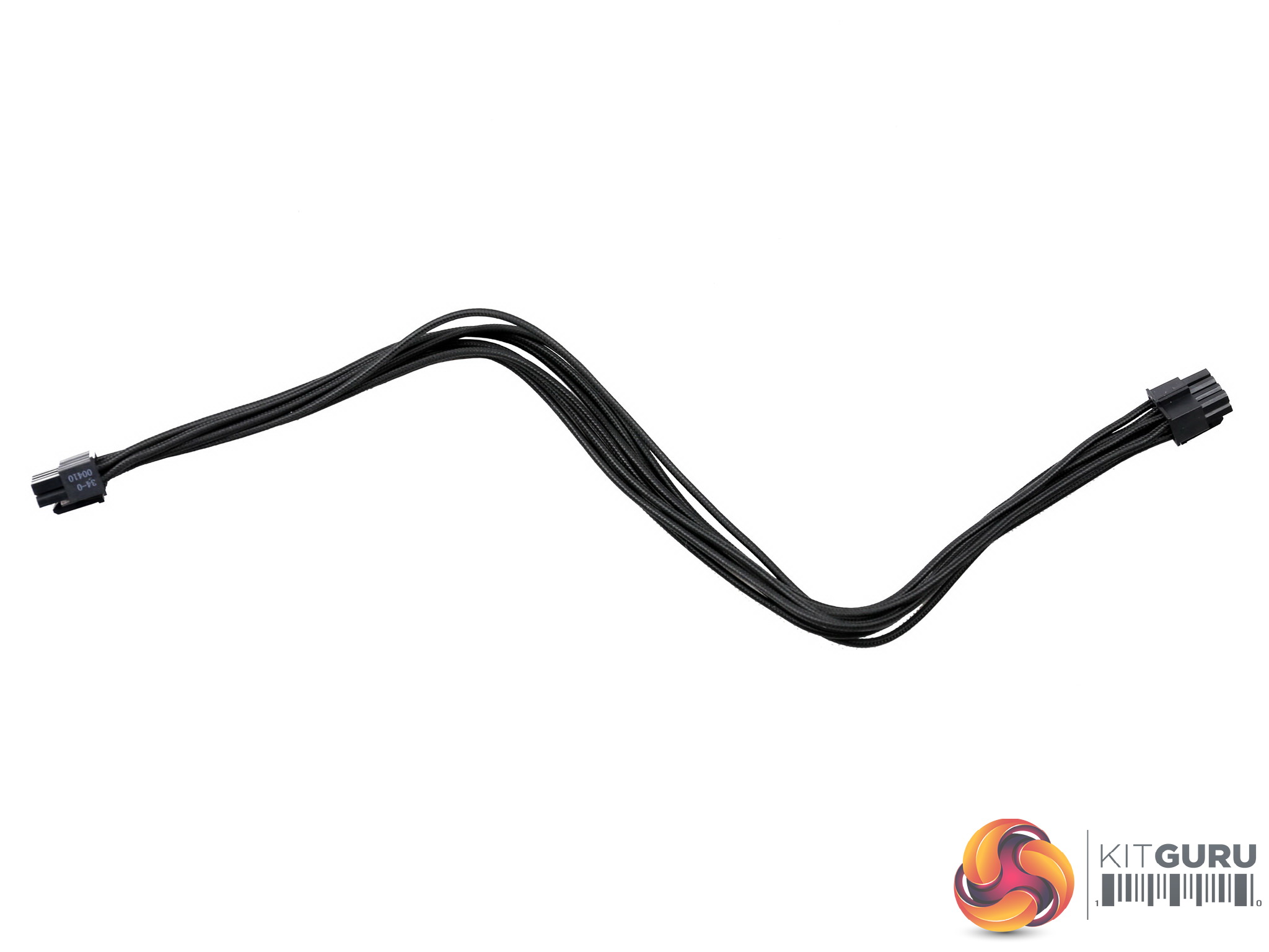
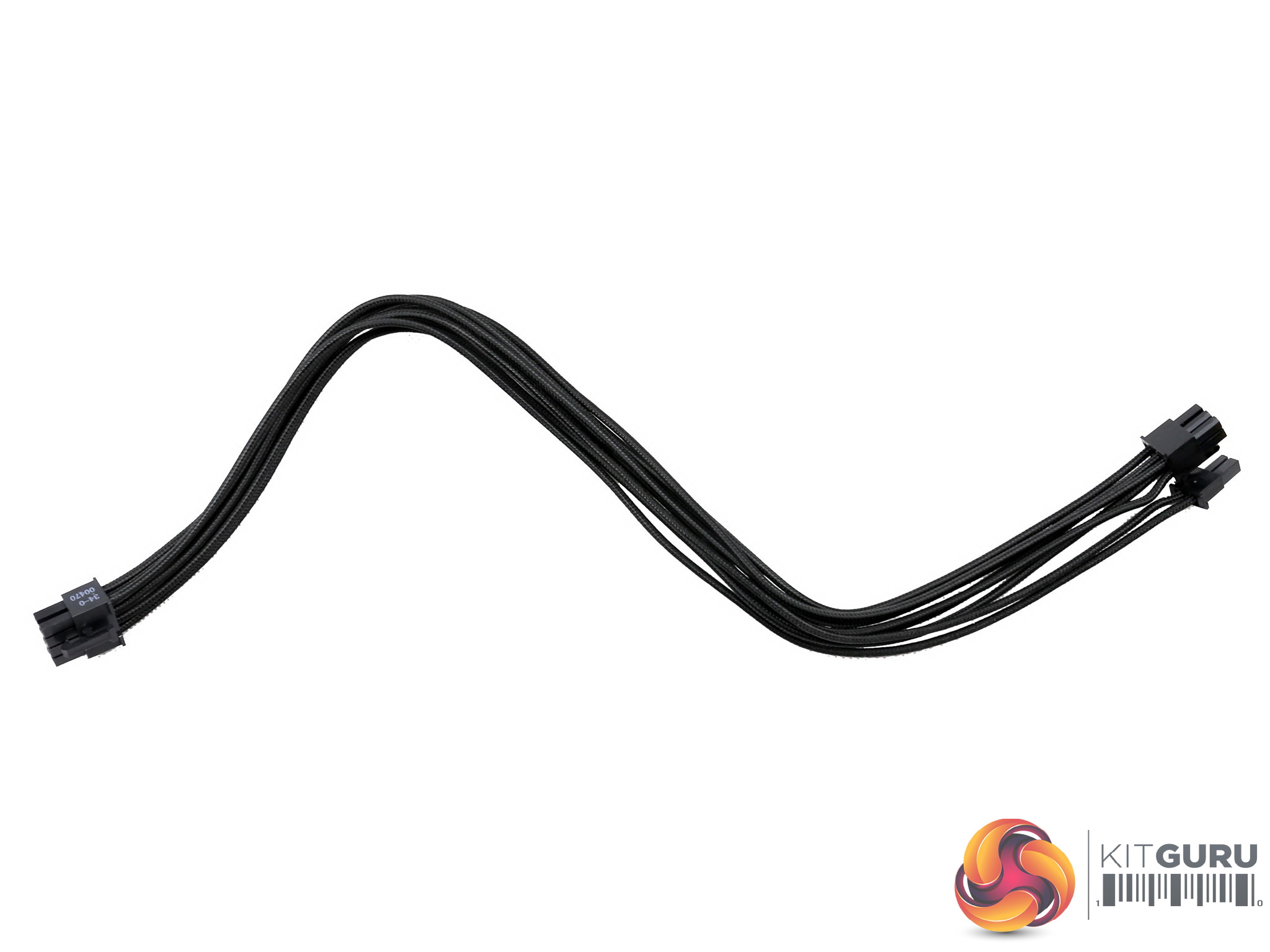
| 6+2 pin PCIe (700mm) | 2 | 2 | 16AWG | No |
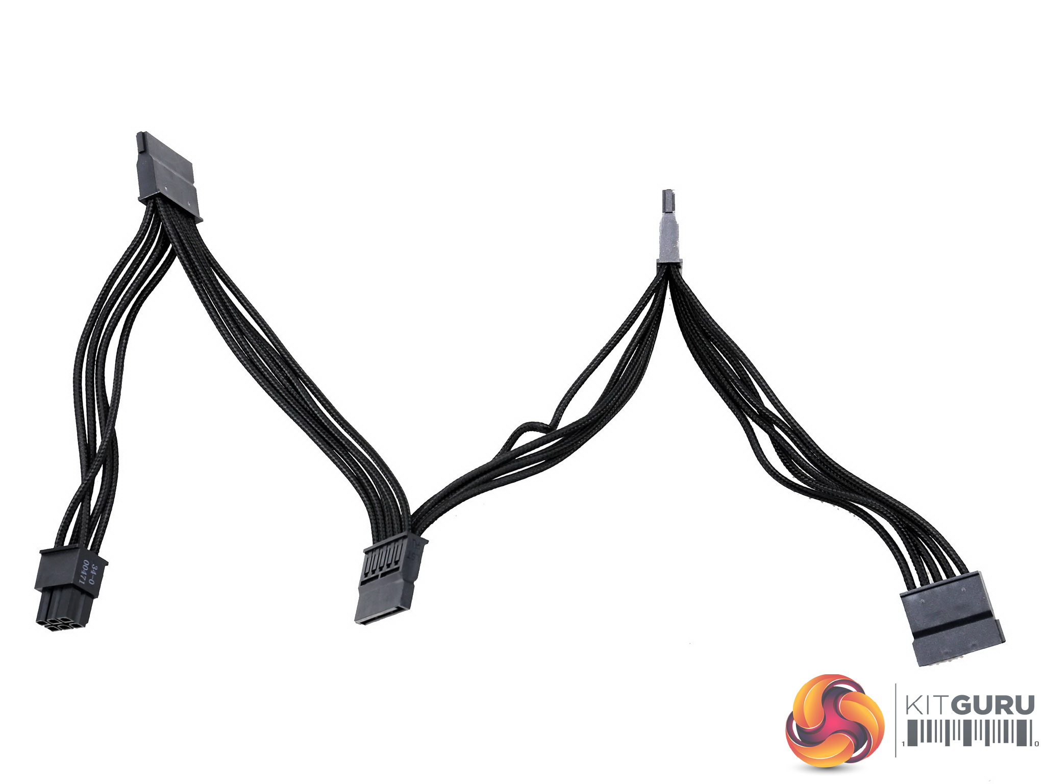
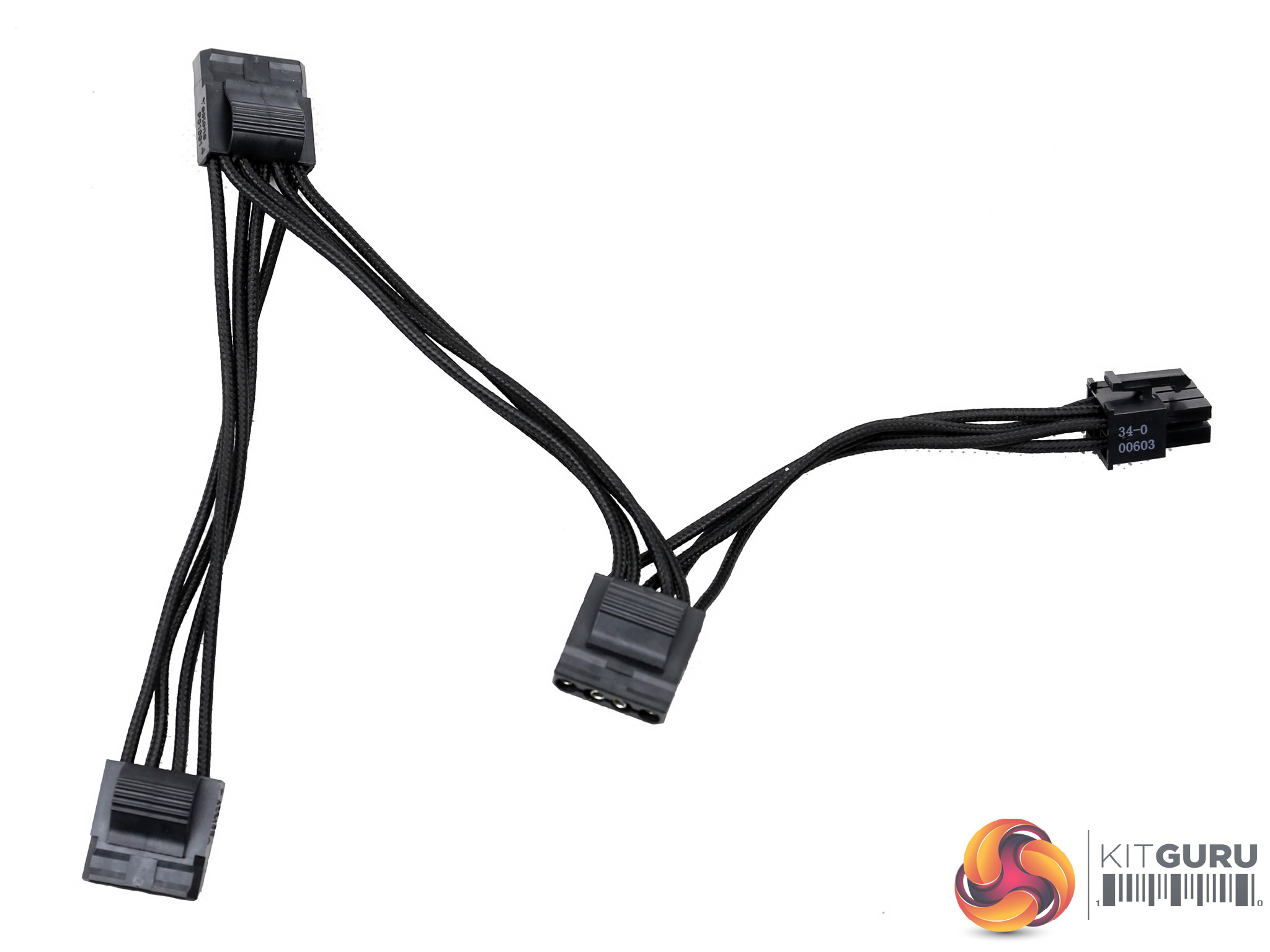
| SATA (100mm+105mm+105mm105mm) | 1 | 4 | 18AWG | No |
| 4 pin Molex (100mm+105mm+105mm) | 1 | 3 | 18AWG | No |
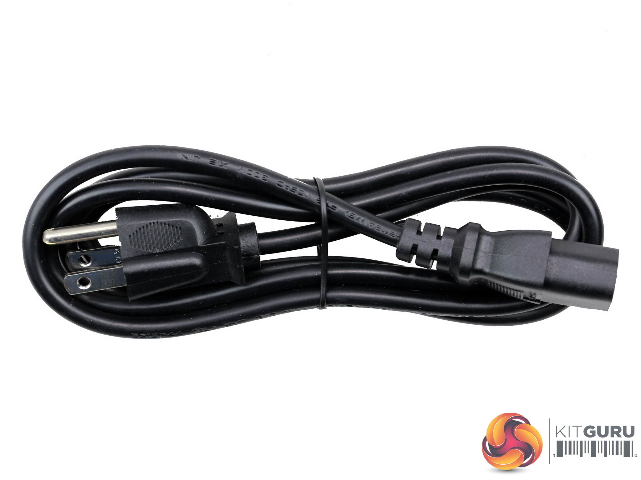
| AC Power Cord (1400mm) | 1 | 1 | 18AWG | – |
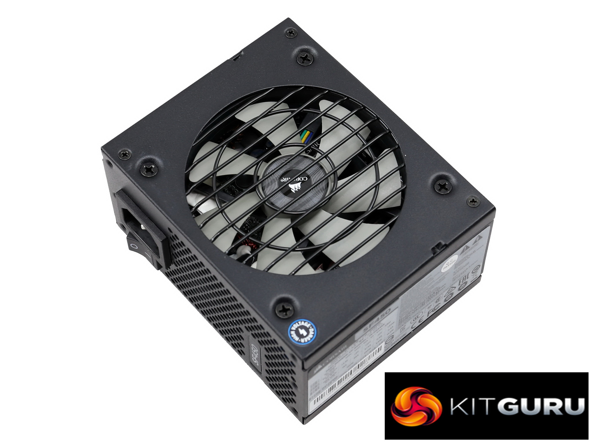
As we already mentioned, the cable configuration is exactly the same as the SF600 Platinum, which is odd since a single EPS and two PCIe connectors might be enough for 450W but they definitely don't allow a 600W power supply to fully exploit its capacity.
The length of the ATX, EPS and peripheral cables is short since this unit will be most likely installed into a small chassis, although Corsair provides an ATX-to-SFX adapter in the bundle allowing you to use it in any ATX chassis. Strangely enough the pair of PCIe cables is very long at 700mm, clearly standing out from all the rest.
The distance between the peripheral connectors is small at 105mm, however this won't create any problems inside a small chassis where all components are close to each other. Finally, it is nice to see 16 AWG gauges in a 450W unit and the lack of in-cable caps is an asset as well, since most users hate seeing them in PSU cables, because they make those cables difficult to work with.
Packaging
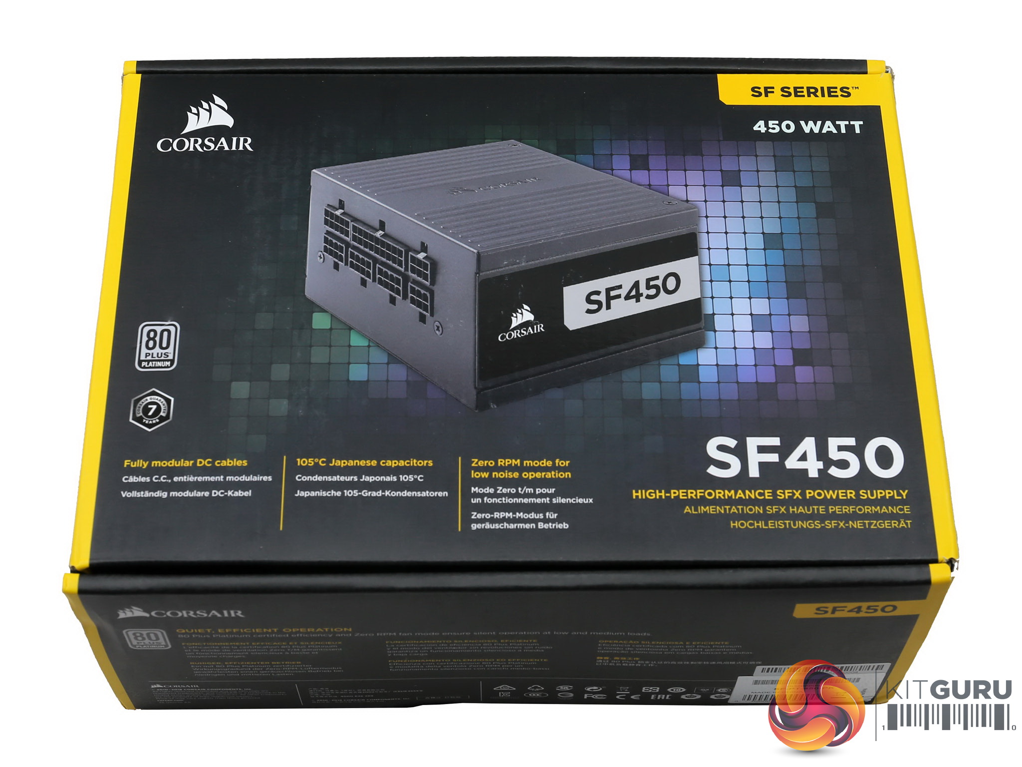
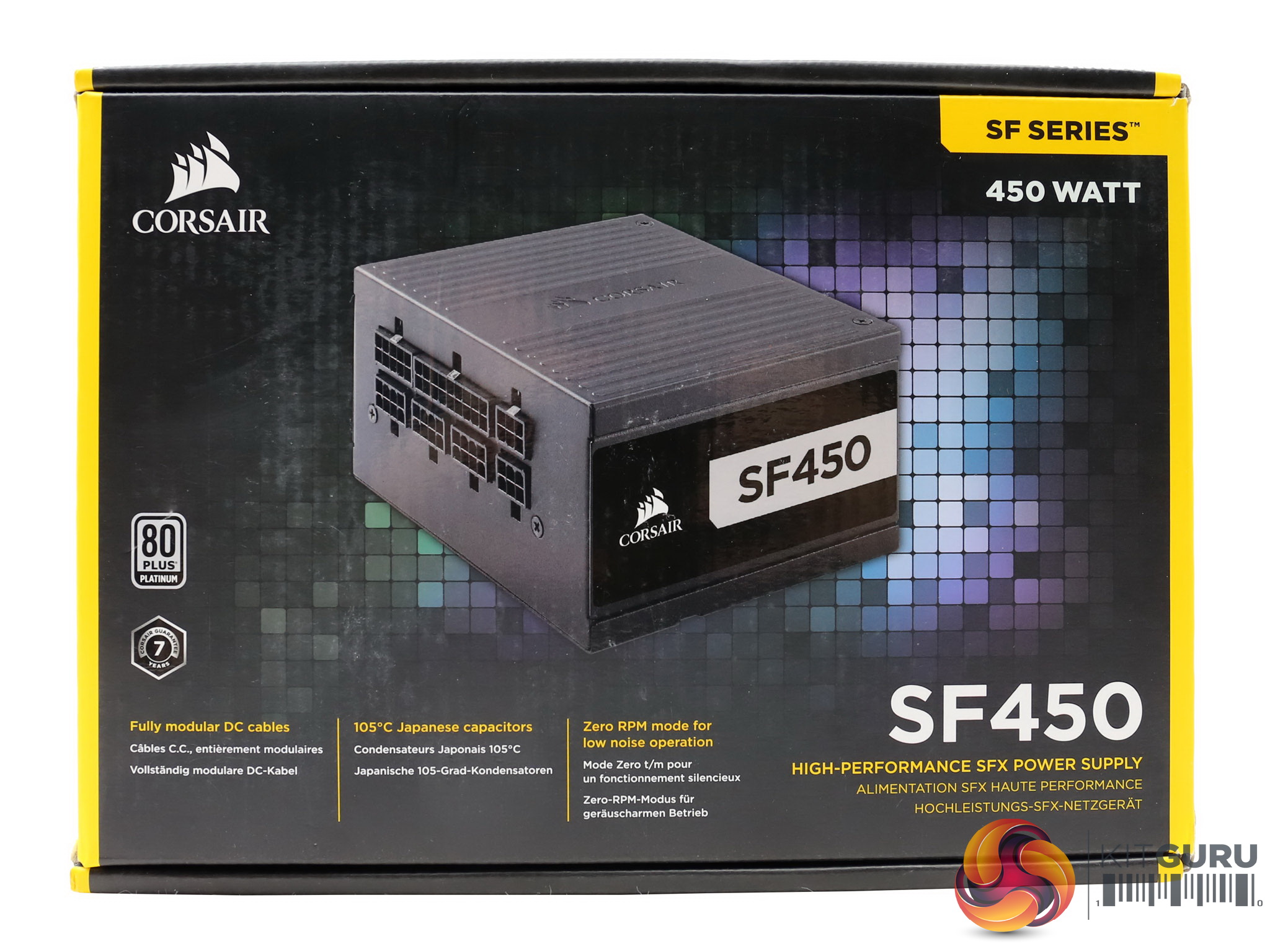
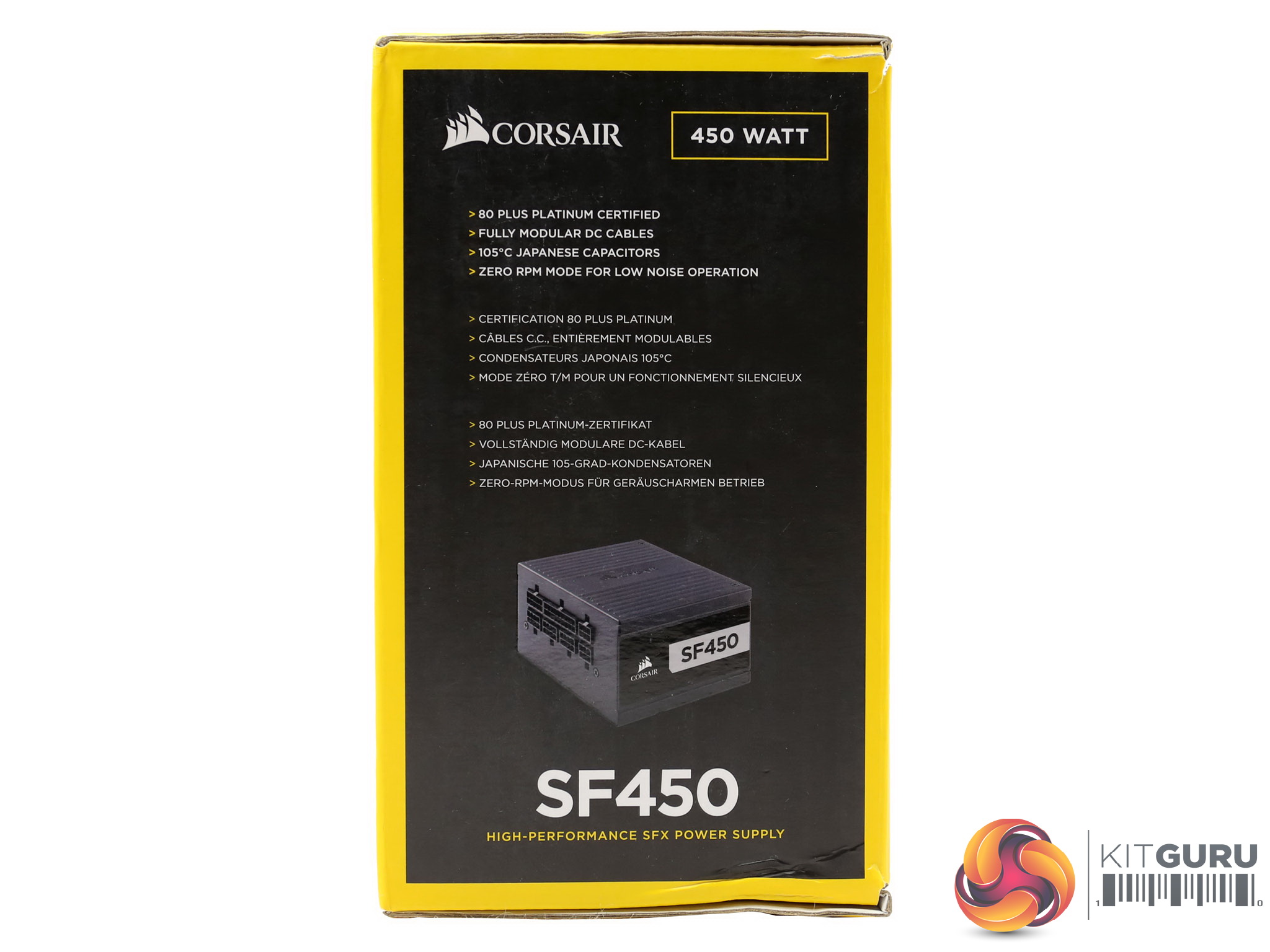
The box is tiny, as it is the power supply inside it. At the front there is an angled photo of the product with the model number highlighted in large white fonts near the bottom-right corner. There “Platinum” word is missing so you will have to look for the 80 PLUS Platinum badge to distinguish the older Gold model from this one.
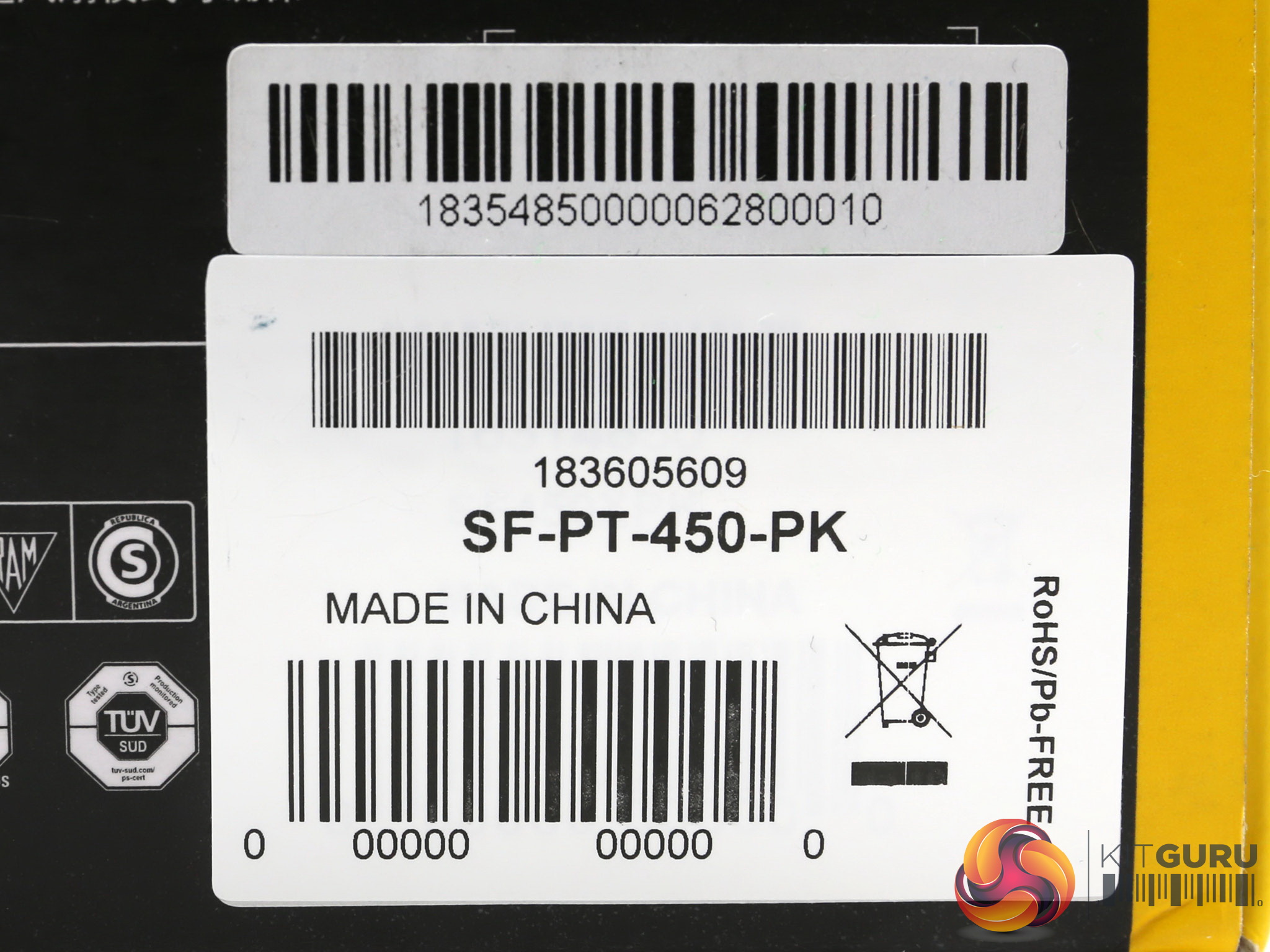
On this side the most interesting part is the sticker with the model and serial numbers. The same sticker depicts the production country which is China, as usual.
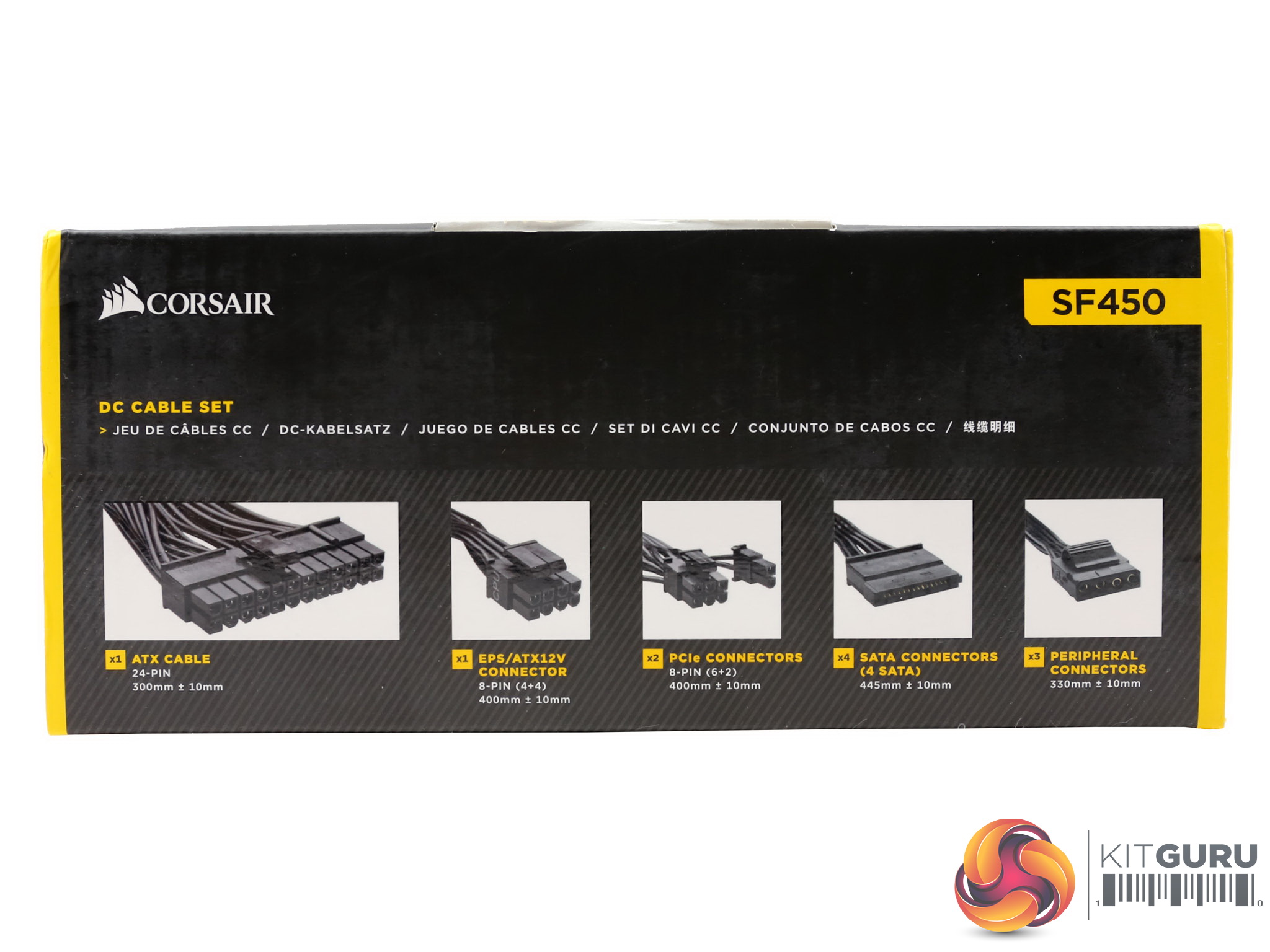
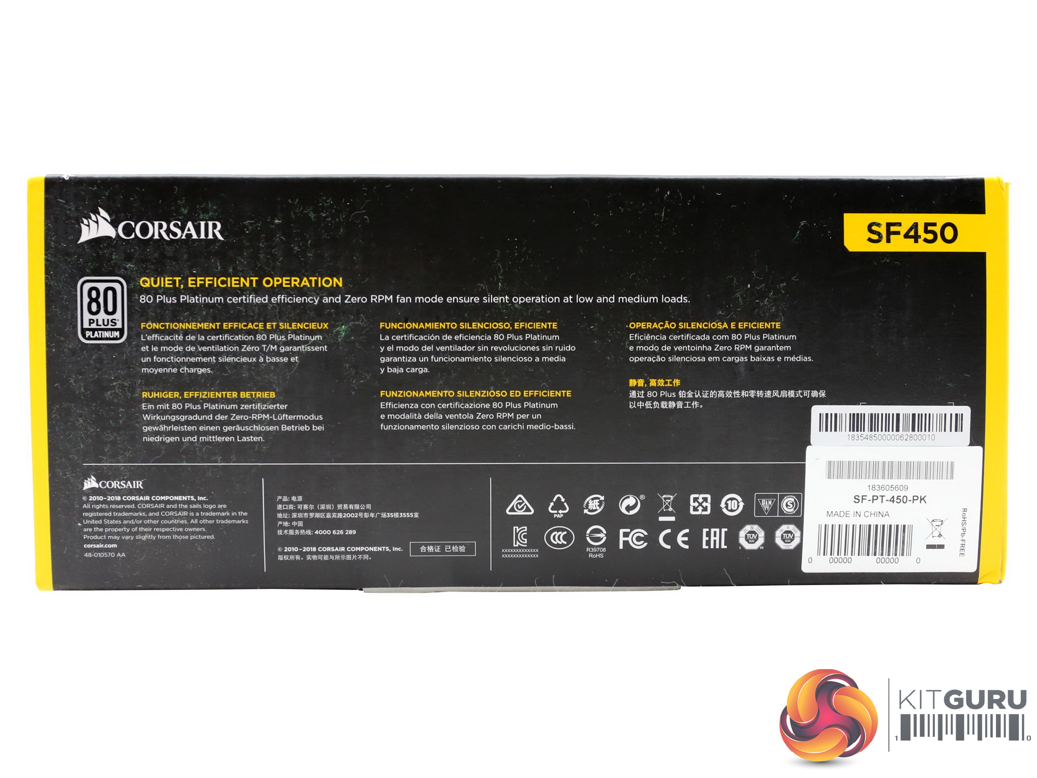
A graphical list of the provided connectors is at the top of the box, while on one of the sides the major features of the product are provided in three languages.
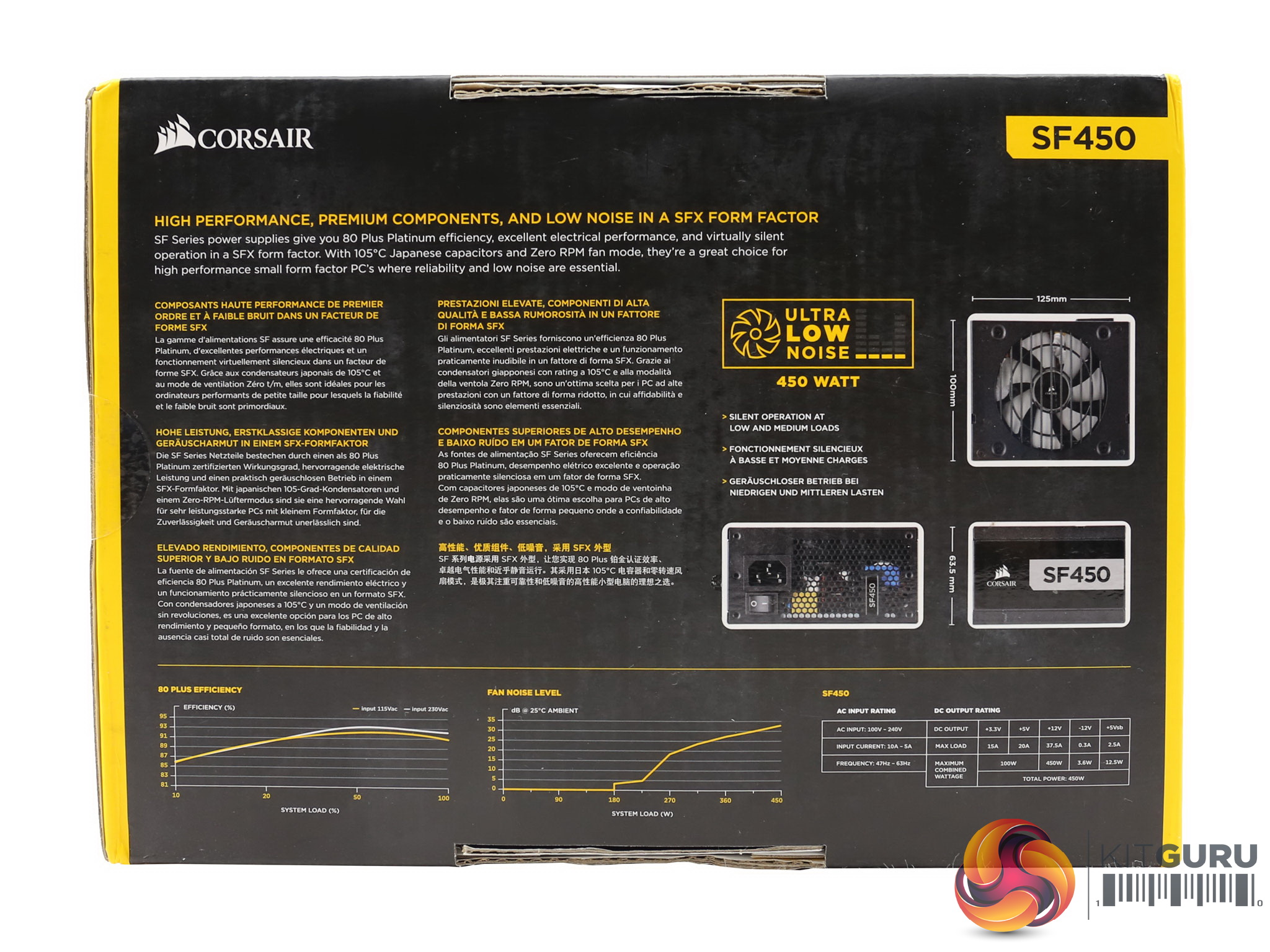
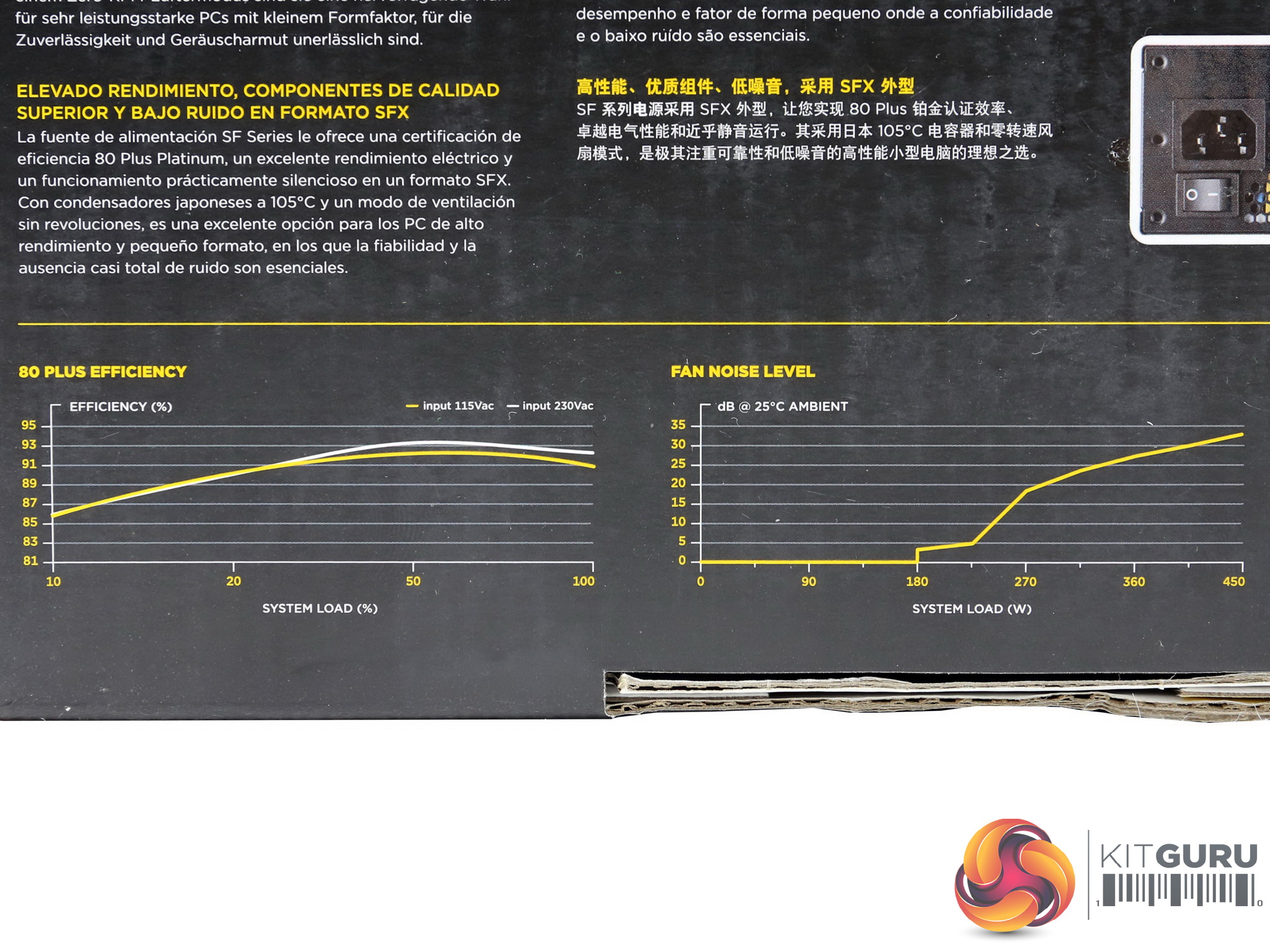
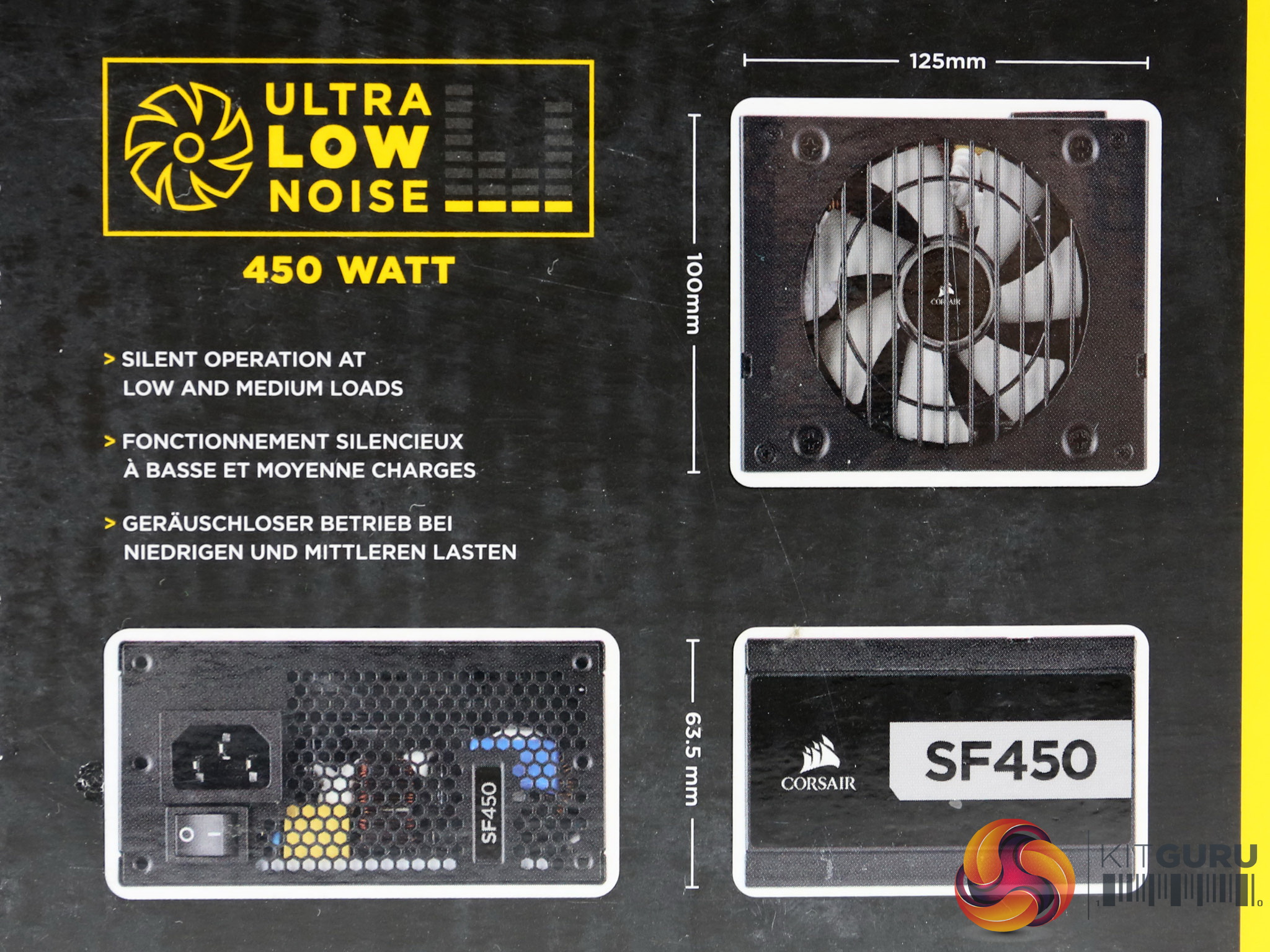
Two graphs showing the efficiency and fan speed/noise can be found at the back, along with the power specifications table and a scheme showing the dimensions of the product.
Contents
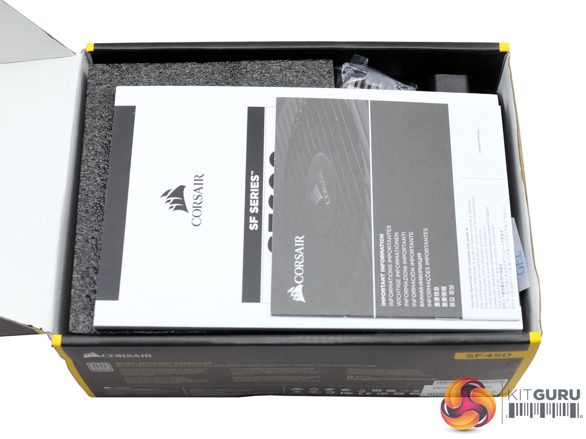
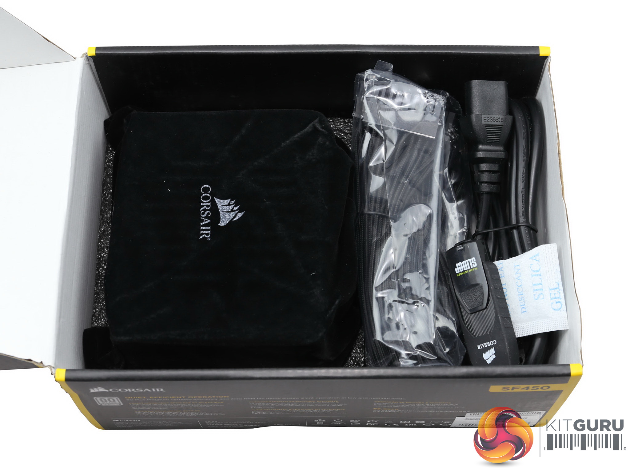
The protection at the internals of the box is adequate, since foam spacers surround the product.

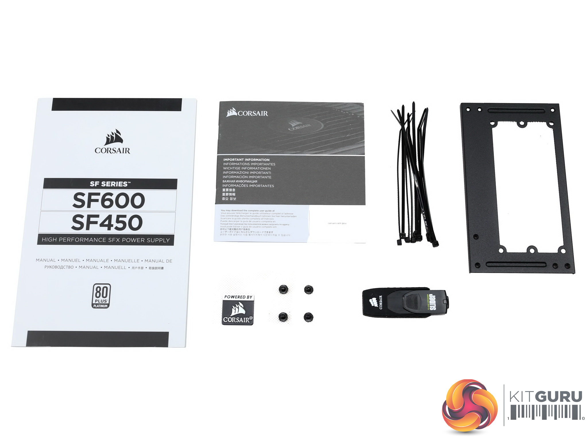
The cloth pouch looks nice and the bundle is rich including a case badge, four fixing bolts, several zip ties, an SFX-to-ATX adapter along with all paper work. The USB flash drive is only for us, reviewers, containing a full evaluation report of the sample, which was created with the help of a fully automatic Chroma station.
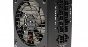
Exterior
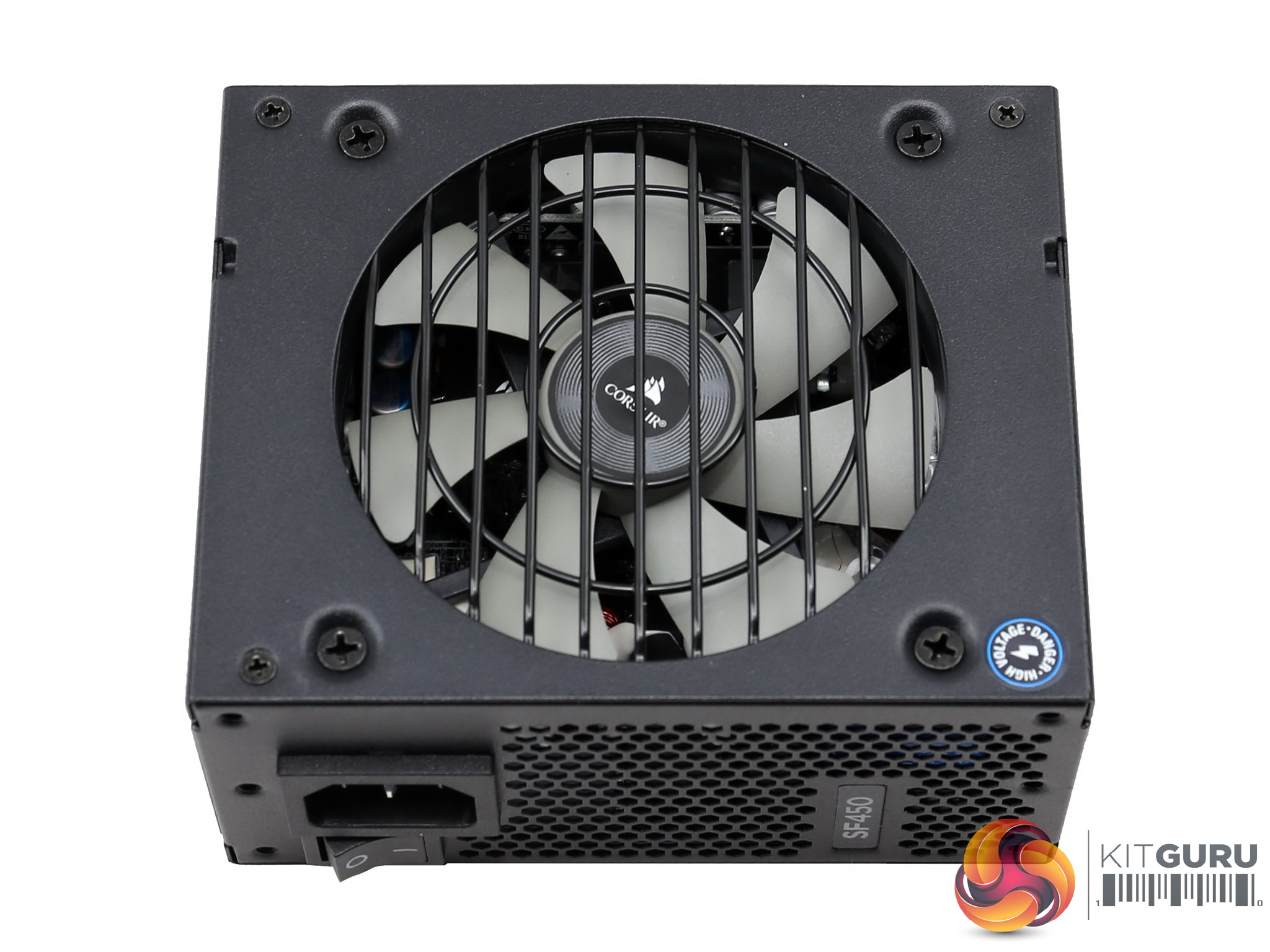
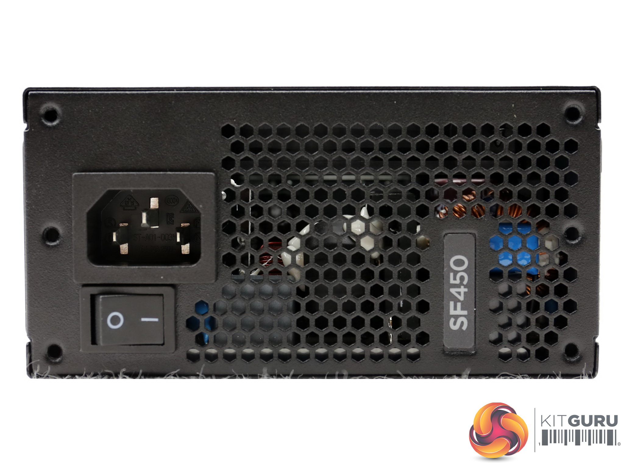
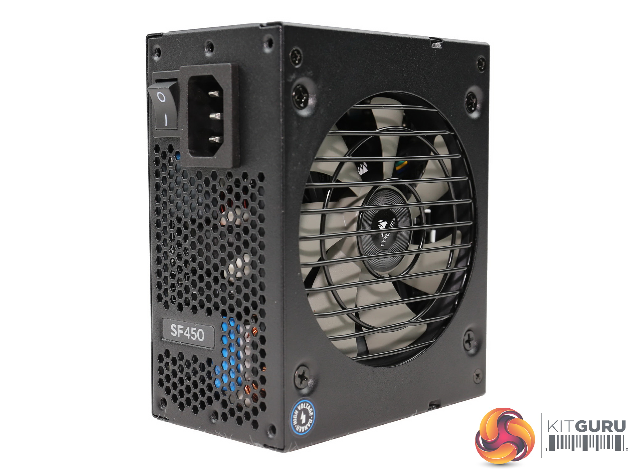
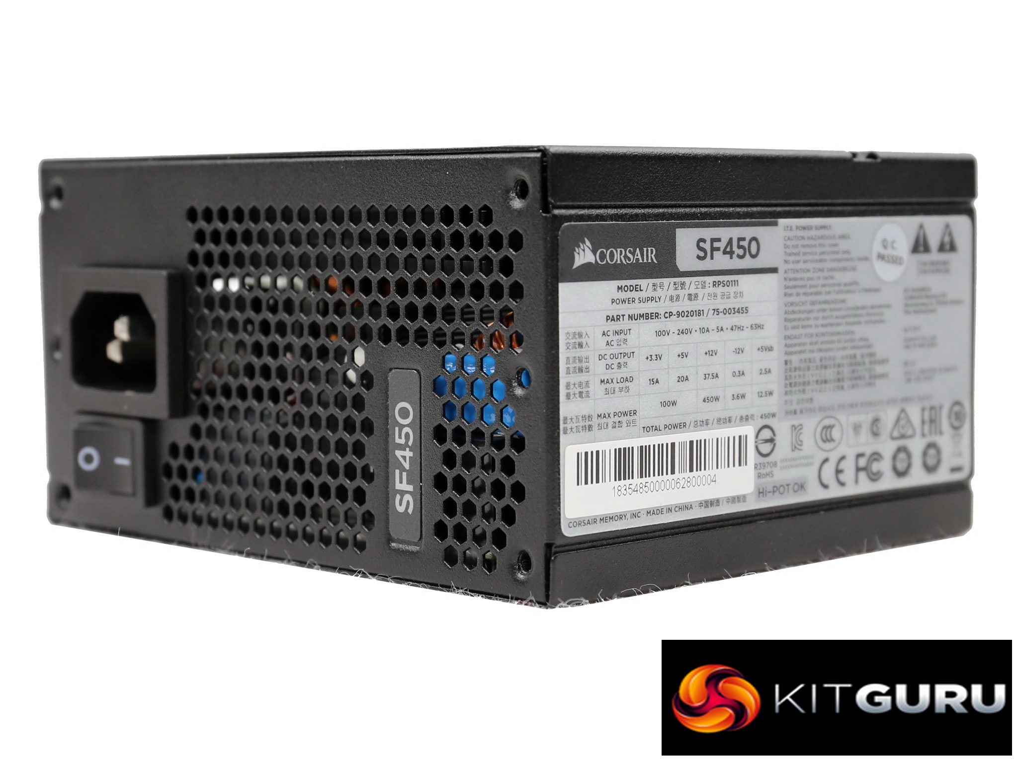
At the front we find the honeycomb-style exhaust grille along with the AC receptacle and a small power switch.
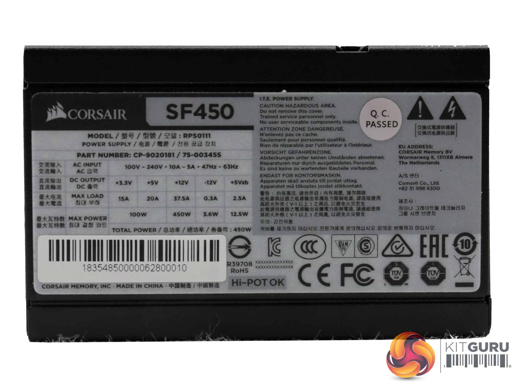
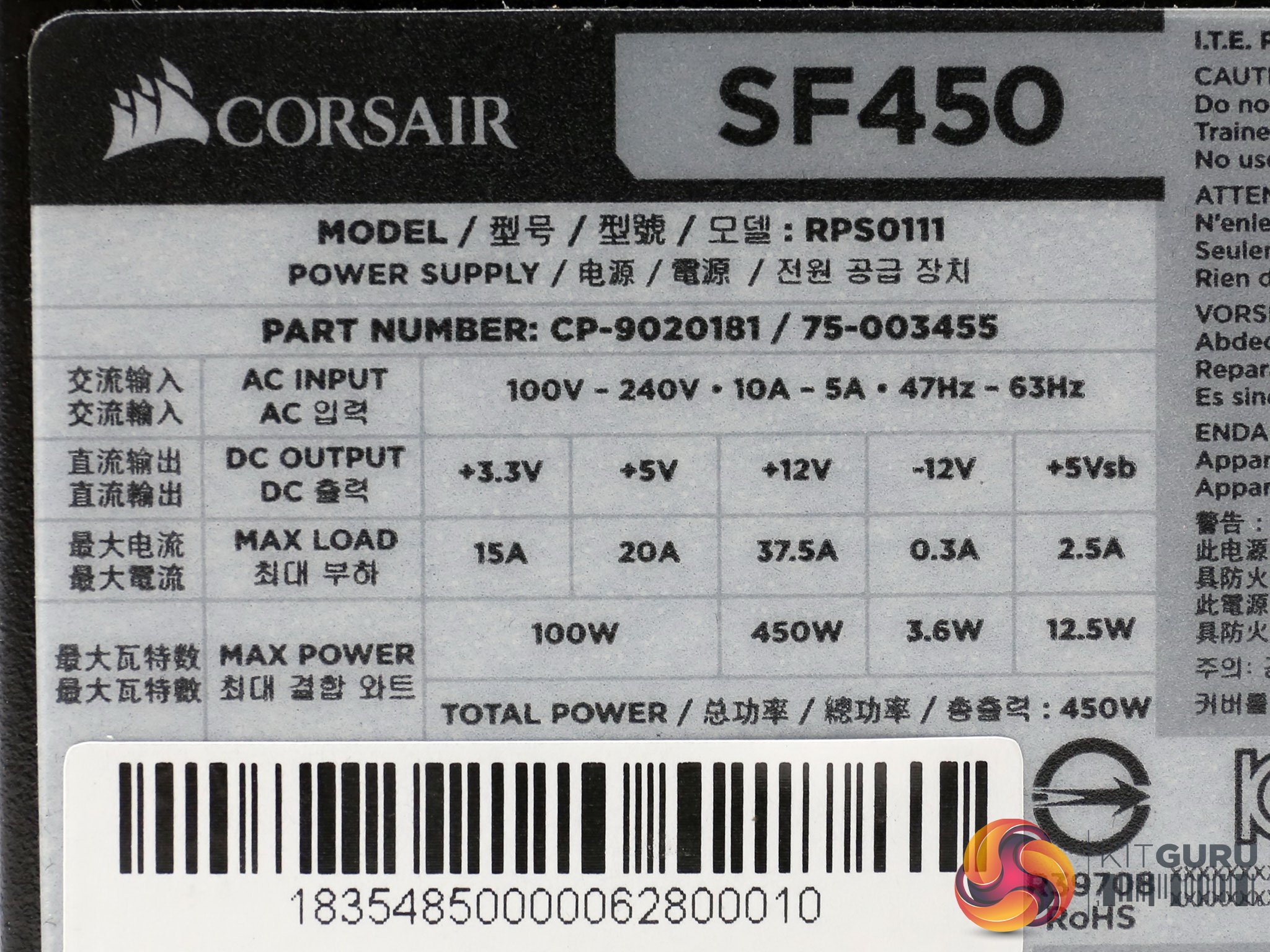
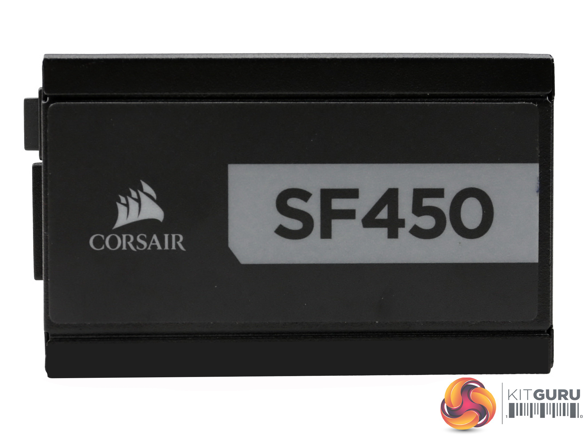
One of the sides hosts the power specifications table which also depicts the product's serial number, while on the opposite side is a sticker showing the model number and Corsair's logo.
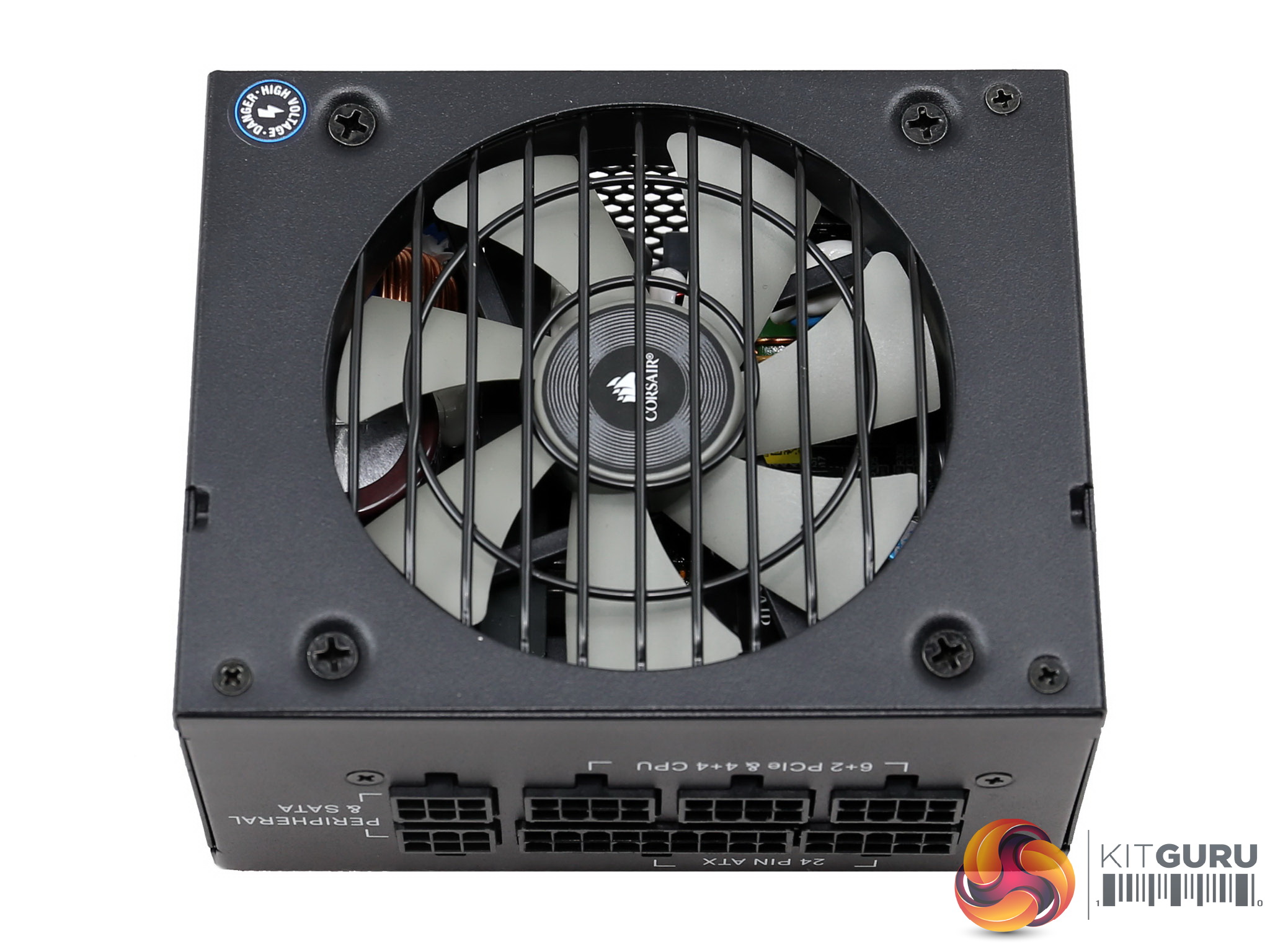
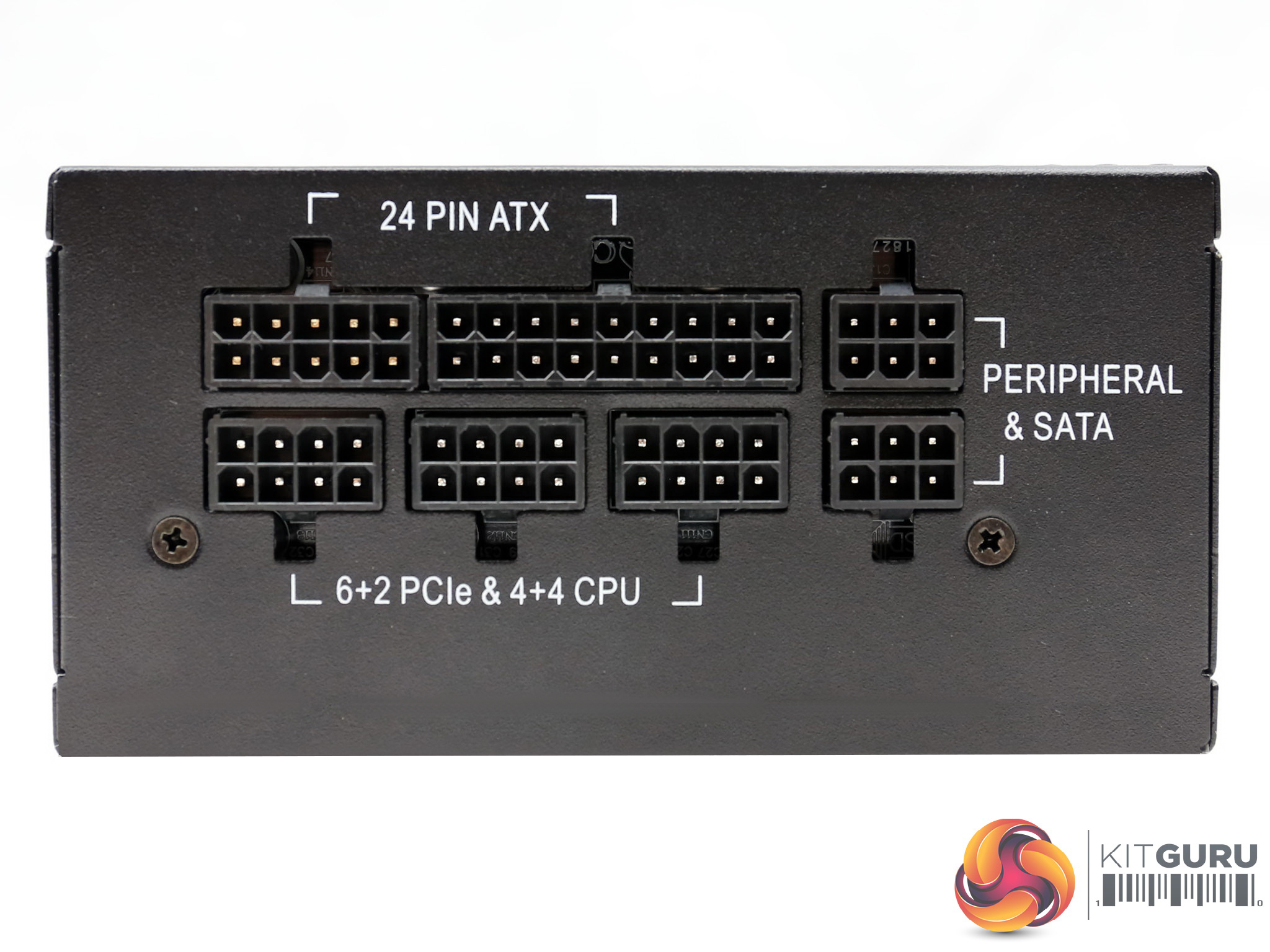
The modular PCB hosts seven sockets, three for the EPS and PCIe cables, two for peripheral and SATA and another pair for the ATX cable.
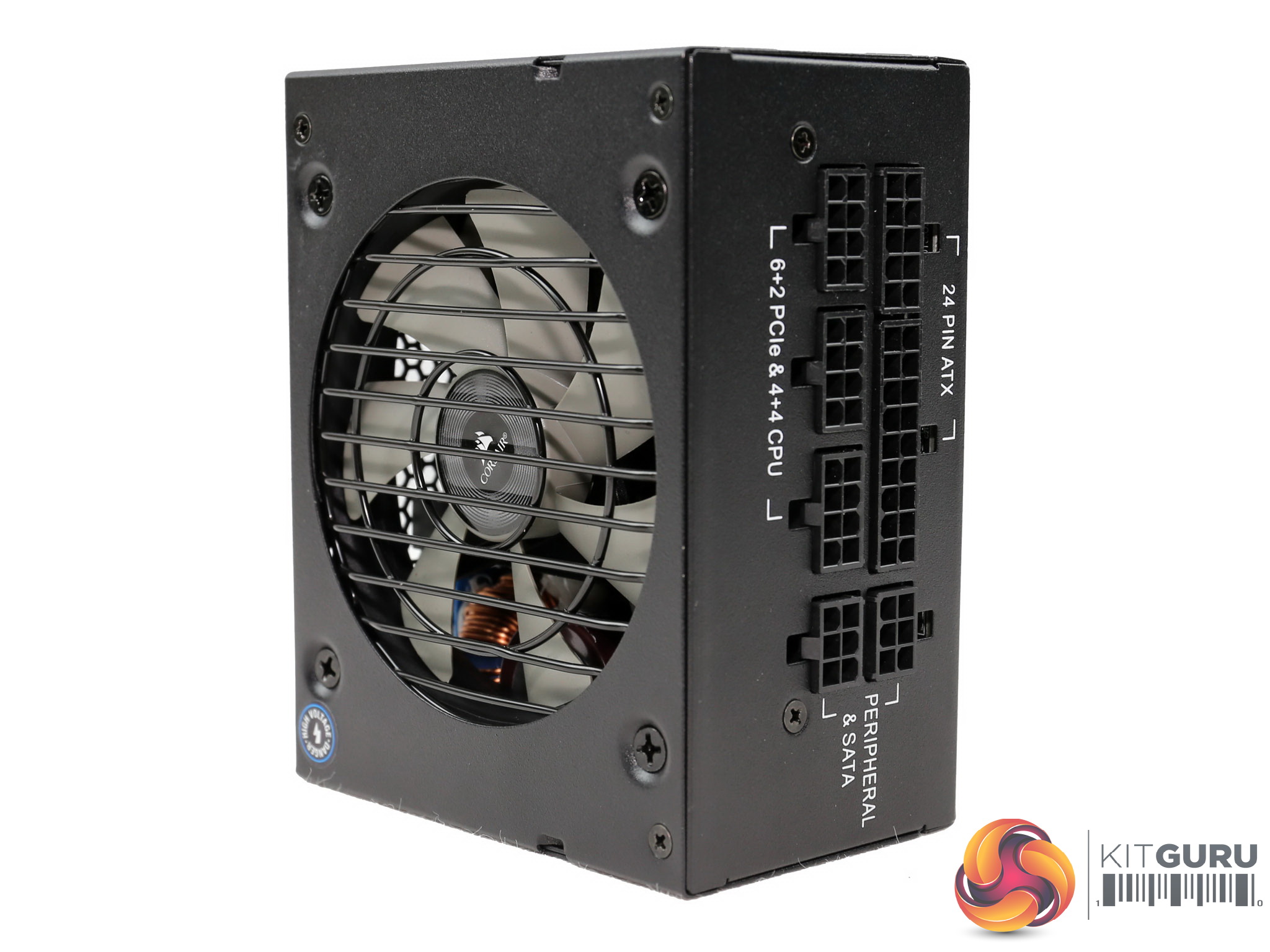
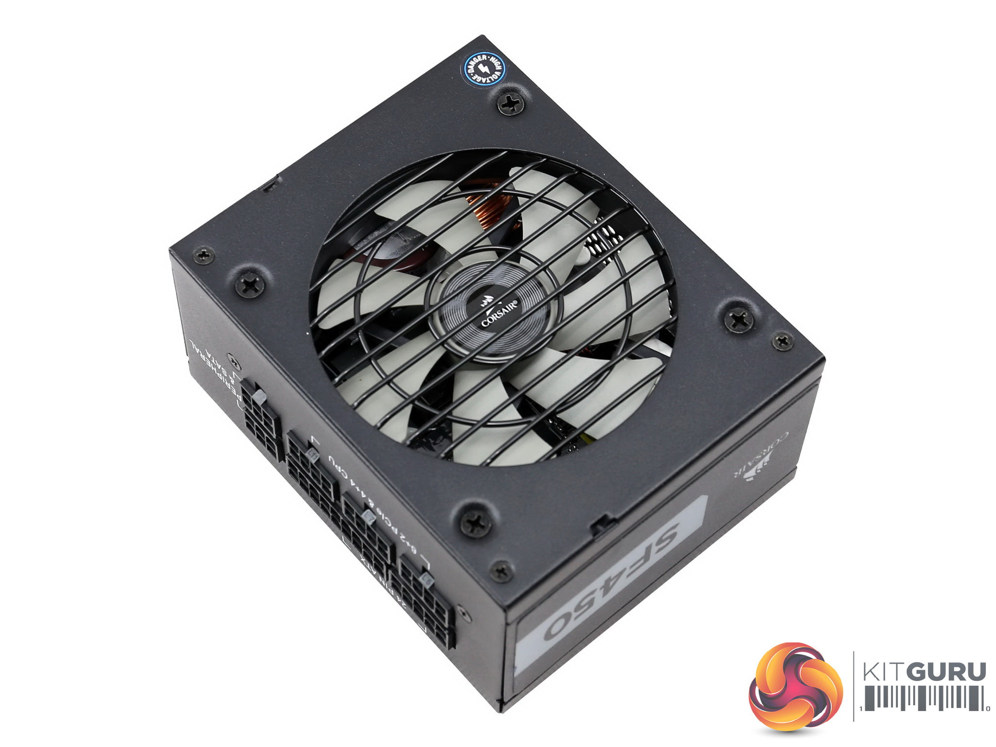
The external design is not fancy, but we won't mind about this from the moment the SF450 delivers good performance. In power supplies everything has to do with performance and efficiency with looks, RGB lighting and other similar features being at the bottom of our list.
| General Data | |
| Manufacturer (OEM) | Great Wall |
| Primary Side | |
| Transient Filter | 4x Y caps, 2x X caps, 3x CM chokes, 1x MOV |
| Inrush Protection | NTC Thermistor & Relay |
| Bridge Rectifier(s) |
1x GBU25KH (800V, 25A @ 125 °C)
|
| APFC MOSFET |
1x Infineon IPZ60R099C7 (650V, 14A @ 100°C, 0.099Ohm)
|
| APFC Boost Diode |
1x Infineon IDH06G65C6 (600V, 6A @ 145°C)
|
| Hold-up Cap(s) |
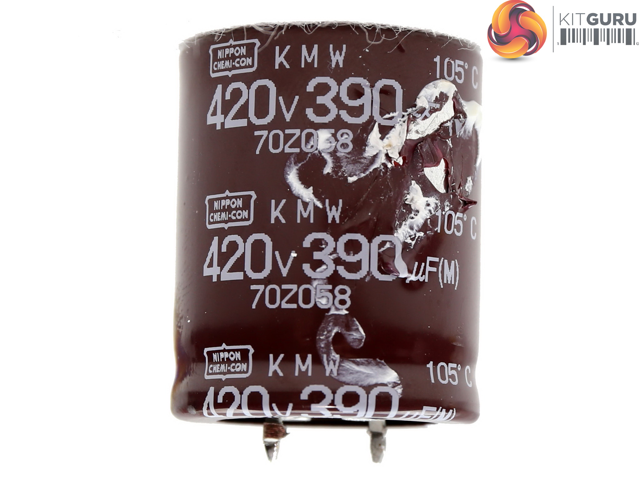
1x Nippon Chemi-Con (420V, 420uF, 2000h @ 105 °C, KMW)
|
| Main Switchers |
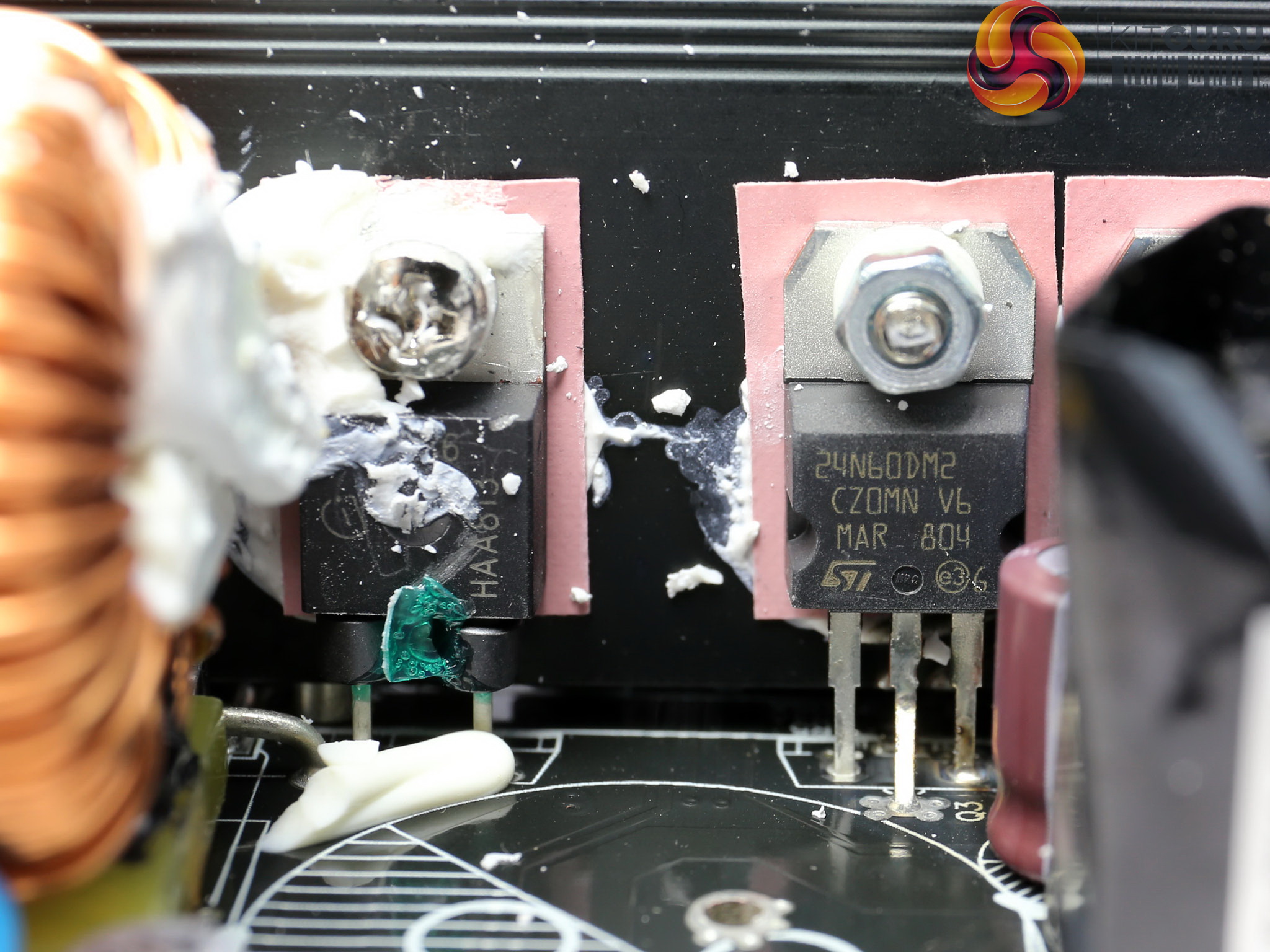
2x STMicroelectronics STP24N60DM2 (650V, 14A @ 100°C, 0.2Ohm)
|
| Driver IC |
Silicon Labs Si8230BD
|
| APFC Controller |
Champion CM6502UHHX & CM03AX Green PFC controller
|
| Resonant Controller |
Champion CM6901X
|
| Topology |
Primary side: Half-Bridge & LLC Resonant Controller
Secondary side: Synchronous Rectification & DC-DC converters |
| Secondary Side | |
| +12V MOSFETS | 2x Infineon BSC014N04LS (40V, 100A @ 100°C, 1.4mOhm) |
| 5V & 3.3V | DC-DC Converters: 4x Nexperia PSMN2R0-30YL (30V, 100A @ 25°C, 2mOhm) PWM Controller: Anpec APW7159C |
| Filtering Capacitors | Electrolytics: 2x Nippon Chemi-Con (4-10,000h @ 105°C, KY), 1x Rubycon (3-6,000h@ 105°C, YXJ) Polymers: Nippon Chemi-Con |
| Supervisor IC | IN1S429I -SCG |
| Fan Control MCU | PIC16F1824 |
| Fan Model | Corsair NR092L (92mm, 12V, 0.22A, 3950 RPM, rifle bearing) |
| 5VSB Circuit | |
| Rectifier |
1x CSD18534 FET (60V, 69A @ 25 °C, 7.8mOhm)
|
| Standby PWM Controller | Infineon ICE5QR1680AG |
The differences with the SF600 Platinum are few including the bulk cap in the APFC converter, the main switching FETs and the FETs that regulate the +12V rail. All the rest parts are exactly the same.
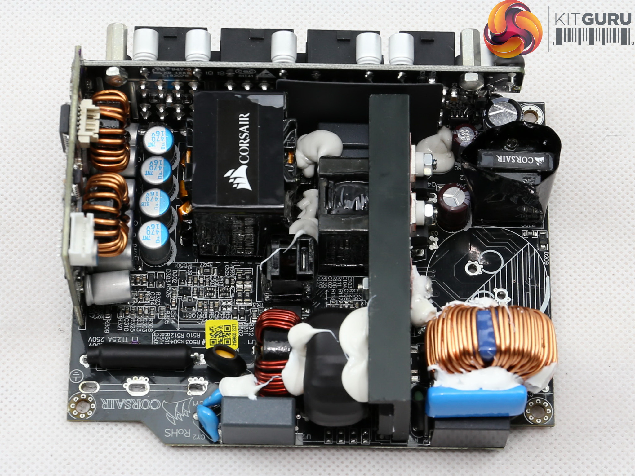
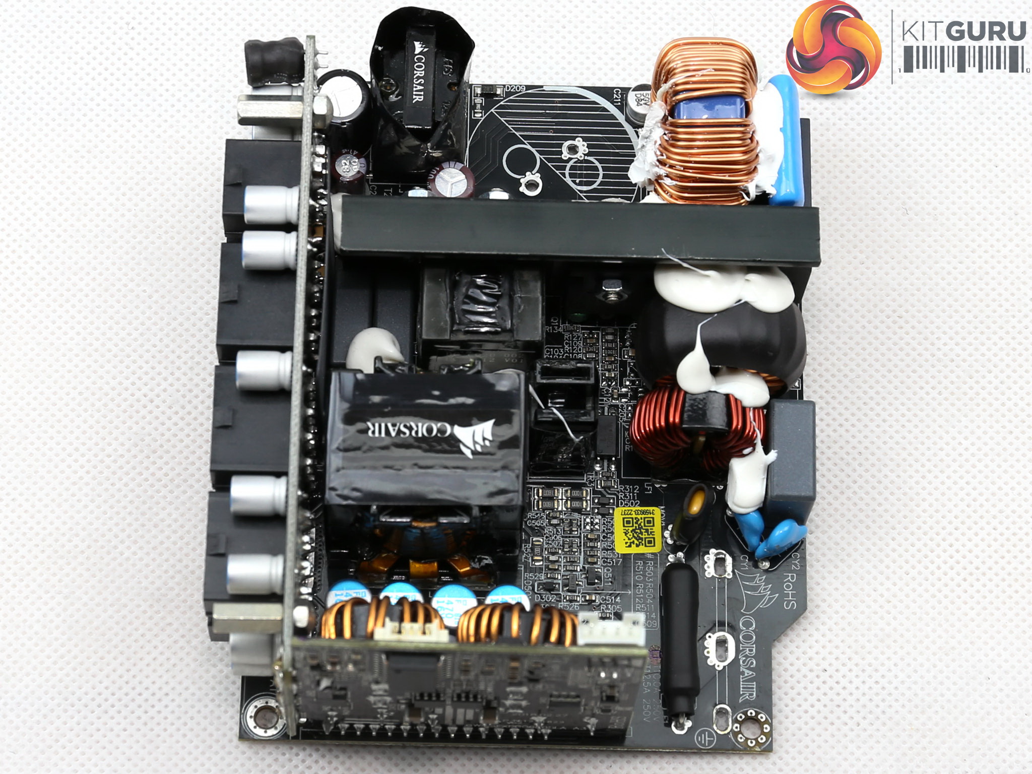
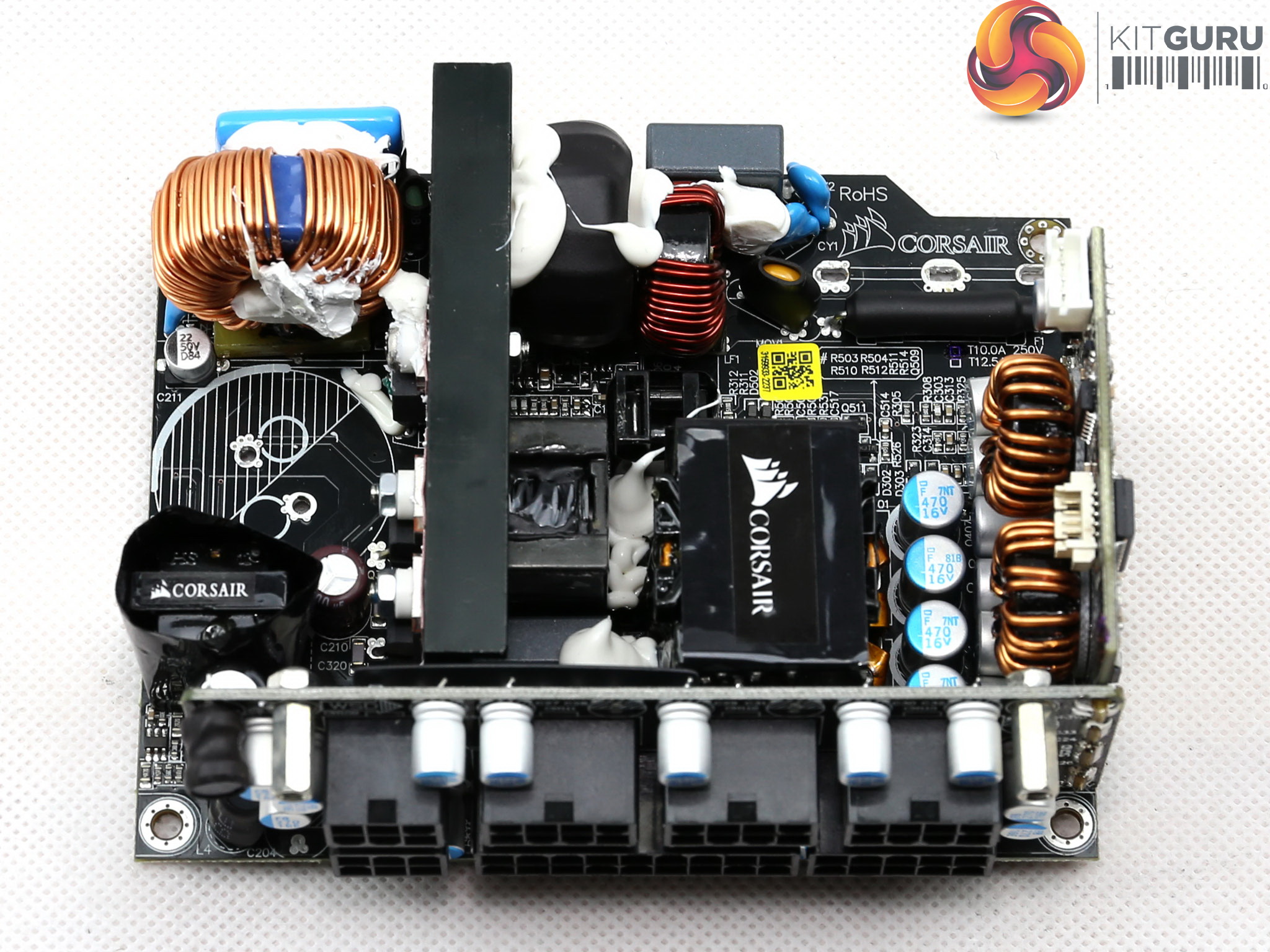
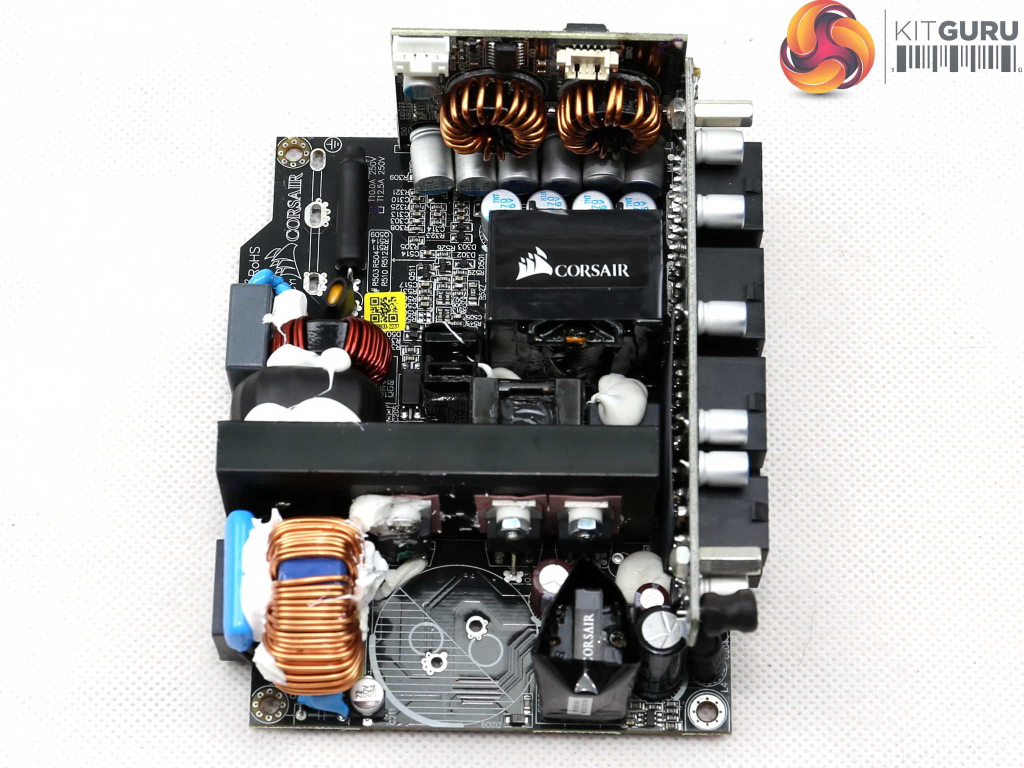
In the primary side a half-bridge topology along with an LLC resonant converter are used, while in the secondary side two FETs, instead of four in the 600W model, regulate the +12V rail. The minor rails are generated by two DC-DC converters and there are only three electrolytic caps, one of which belongs to the 5VSB circuit.
All the rest of the capacitors in the secondary side are polymers, which can cope much better with increased heat compared to electrolytic caps (but lack their capacity). In general this is a very well made platform, with lots of clearance in the secondary side for increased airflow.
![]()
![]()
![]()
![]()
![]()
![]()
![]()
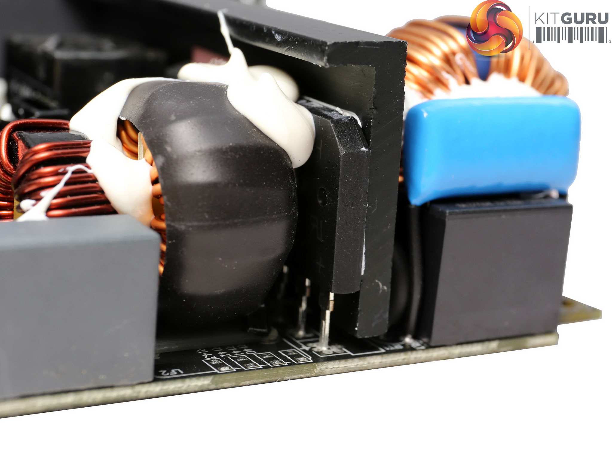
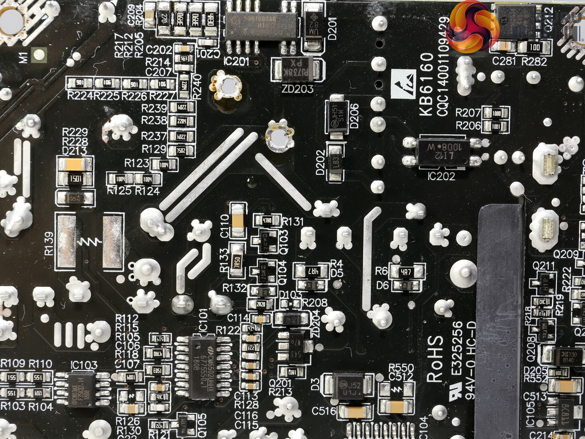
A small PCB behind the AC receptacle holds one CM choke, two Y and one X caps. The second part of the EMI filter on the main PCB consists of the same number of Y and X caps, two CM chokes and an MOV that protects against spikes and power surges coming from the mains grid.
The single bridge rectifier is a powerful GBU25KH which can handle up to 25 Amps of current.
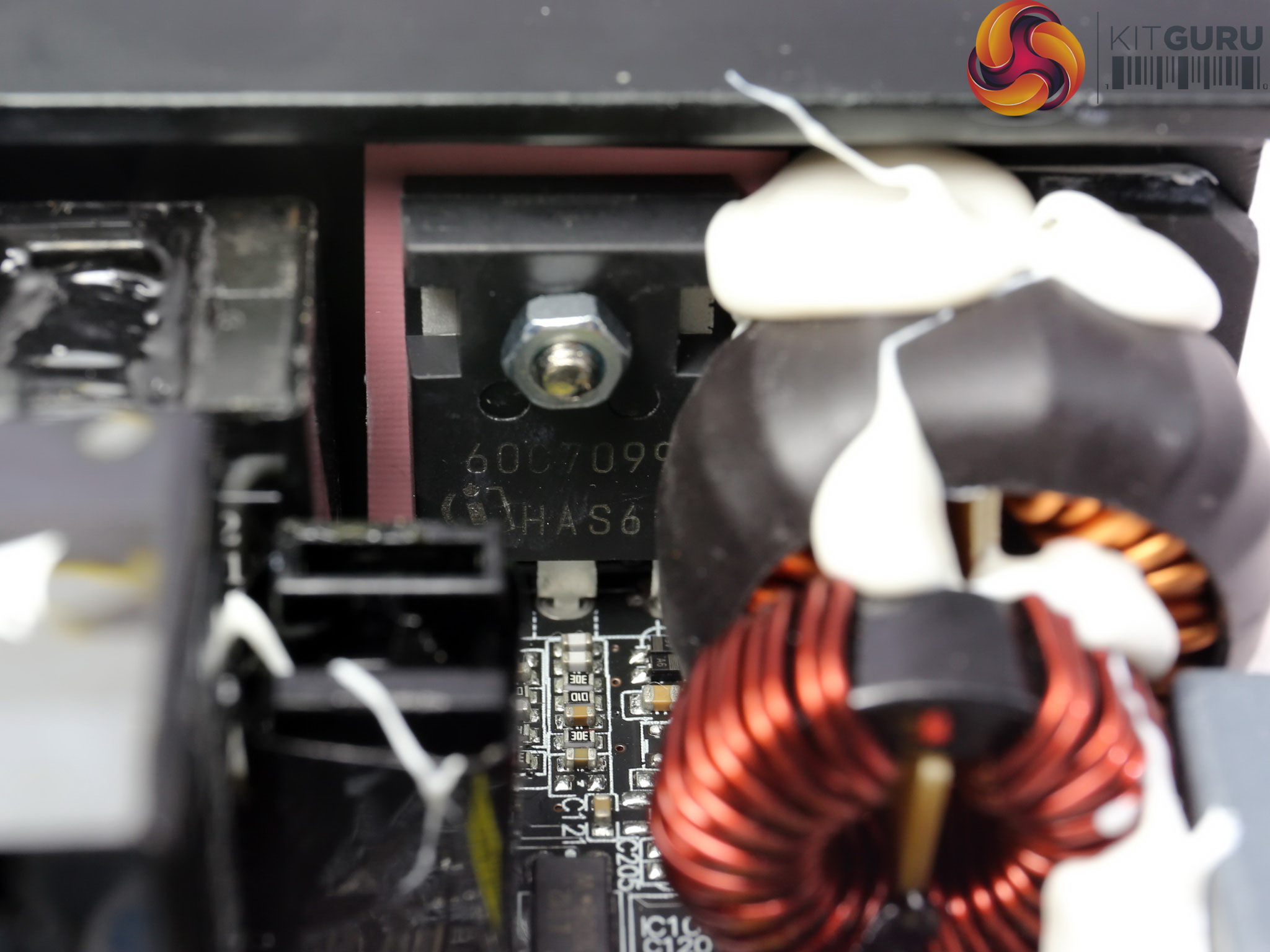

The APFC converter uses a single Infineon IPZ60R099C7 FET and a IDH06G65C6 boost diode, provided by the same manufacturer. As it seems Great Wall decided that there was no need for two FETs in this circuit, something that usually is the case in the majority of power supplies that we evaluate.
The bulk cap belongs to Chemi-Con's quality KMW line and has 420uF capacity, which is enough to provide 17ms of hold-up time. The NTC thermistor along with its bypass relay are located after the bridge rectifier and are installed below the PFC's input capacitor.
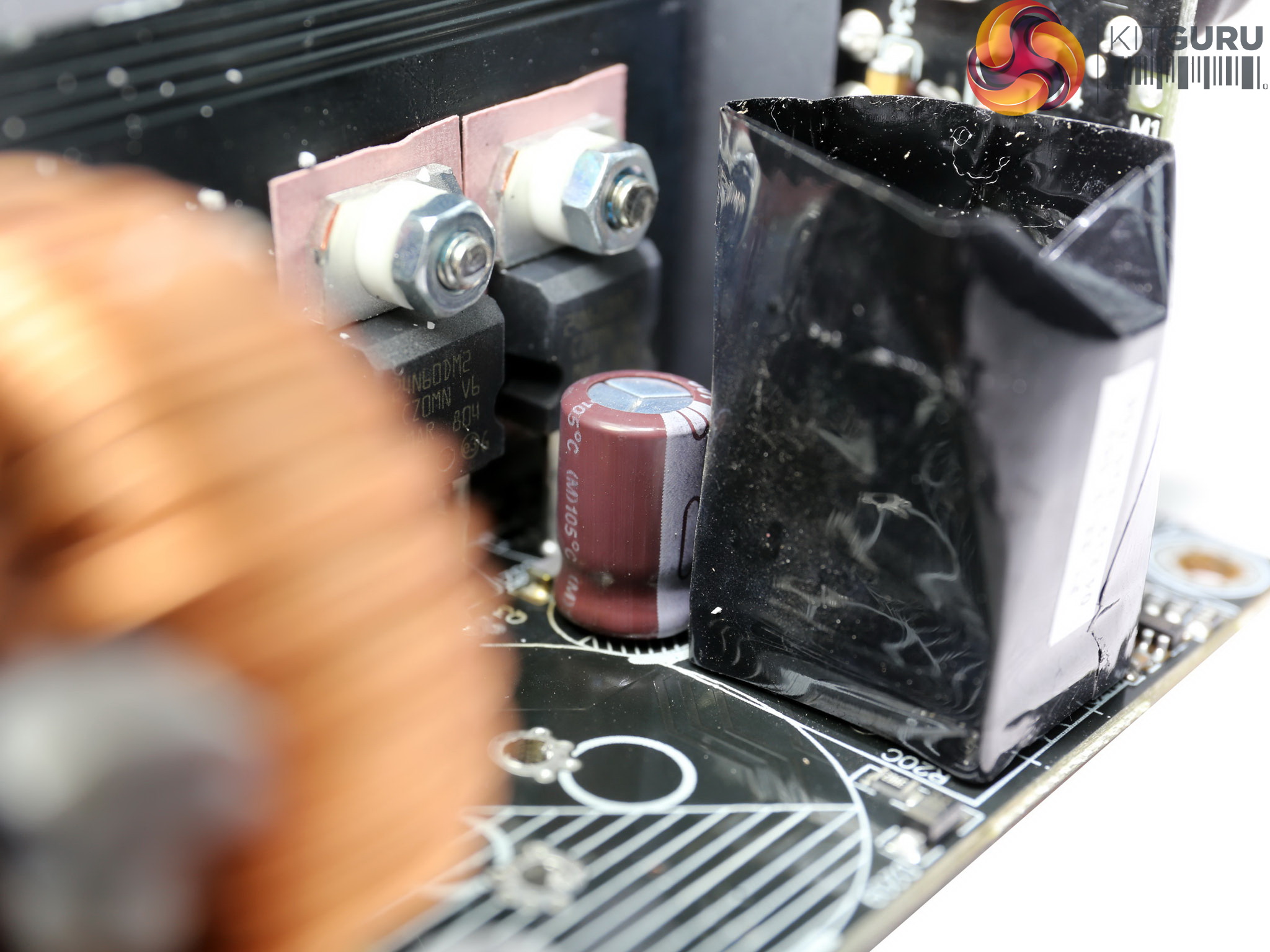
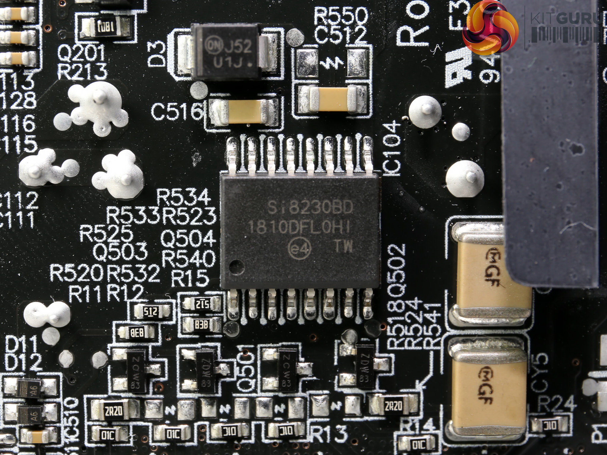
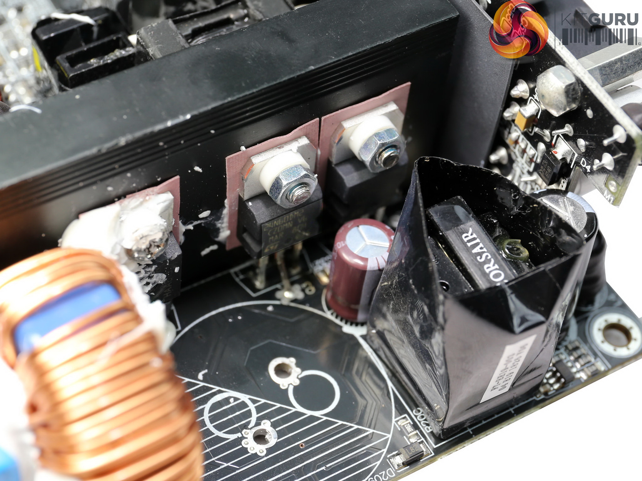
The pair of main FETs, two STMicroelectronics STP24N60DM2 is configured into a half-bridge topology. An LLC resonant converter boosts efficiency by reducing the switching losses. The driver IC of the main FETs is a Silicon Labs Si8230BD.
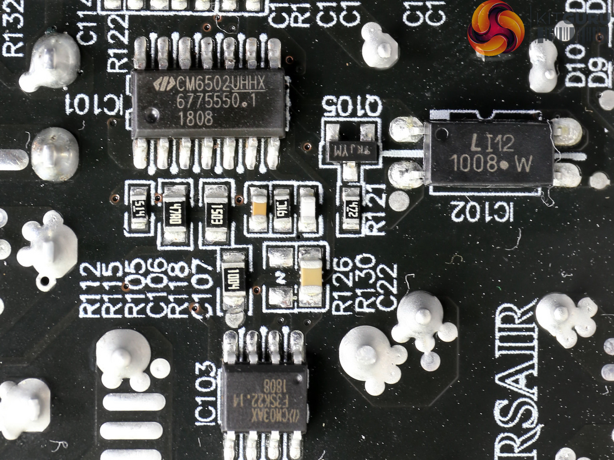
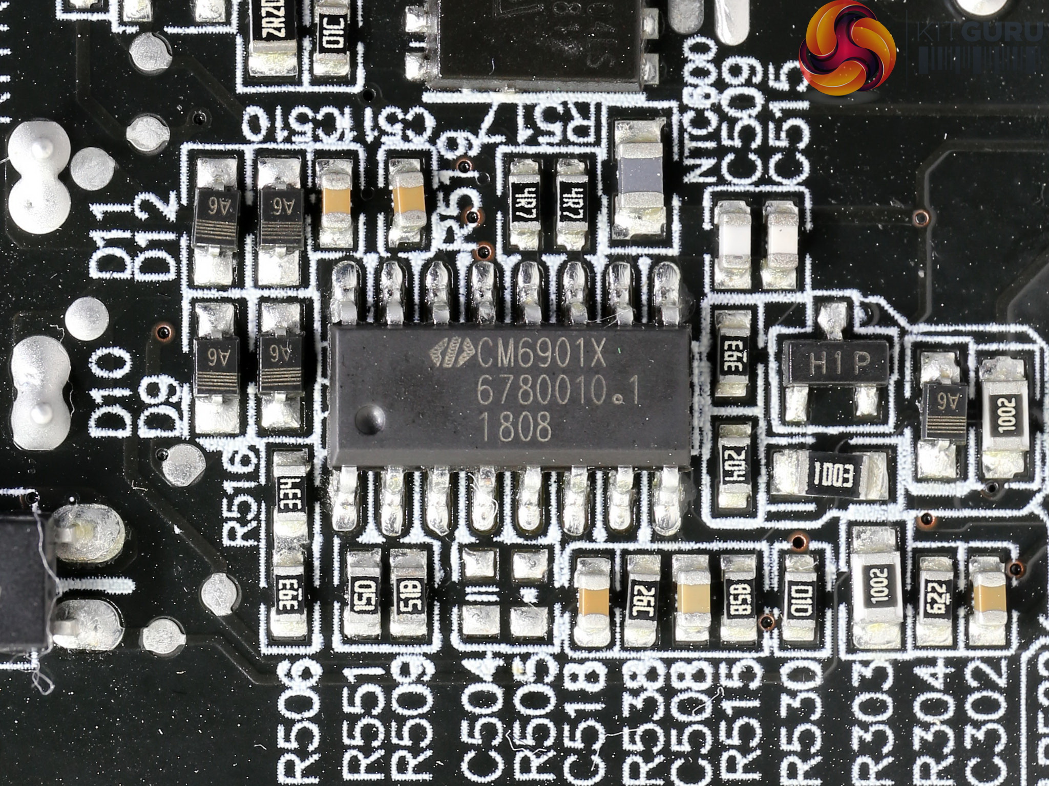
The APFC controller, a Champion CM6502UHHX, is supported by a CM03AX Green PFC controller. Both are installed on the solder side of the board. Close by we also find the resonant controller, the highly popular Champion CM6901X.
![]()
The main transformer.

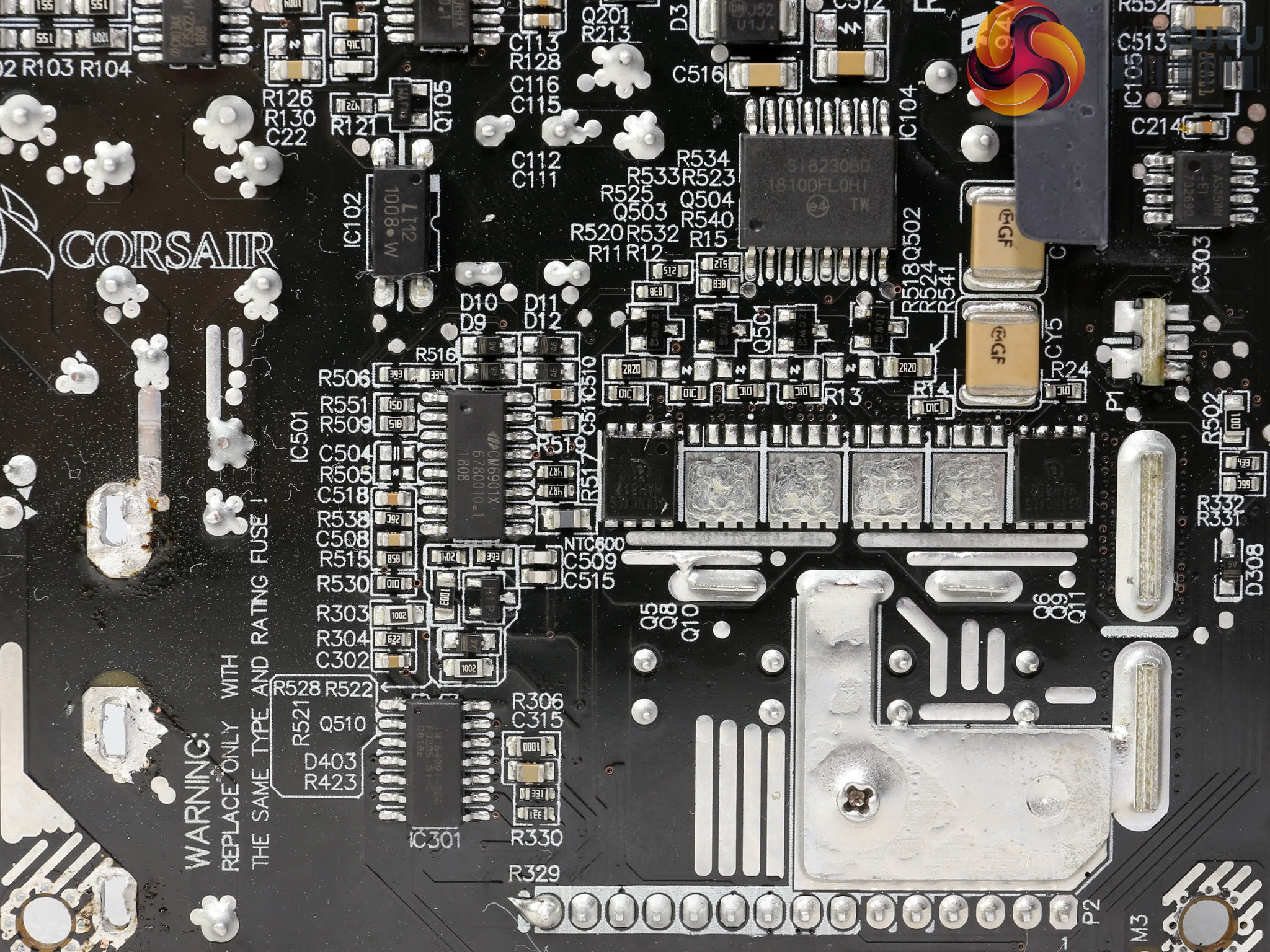
The +12V rail is regulated by two Infineon BSC014N04LS FETs. As you can see there is room for four more FETs.
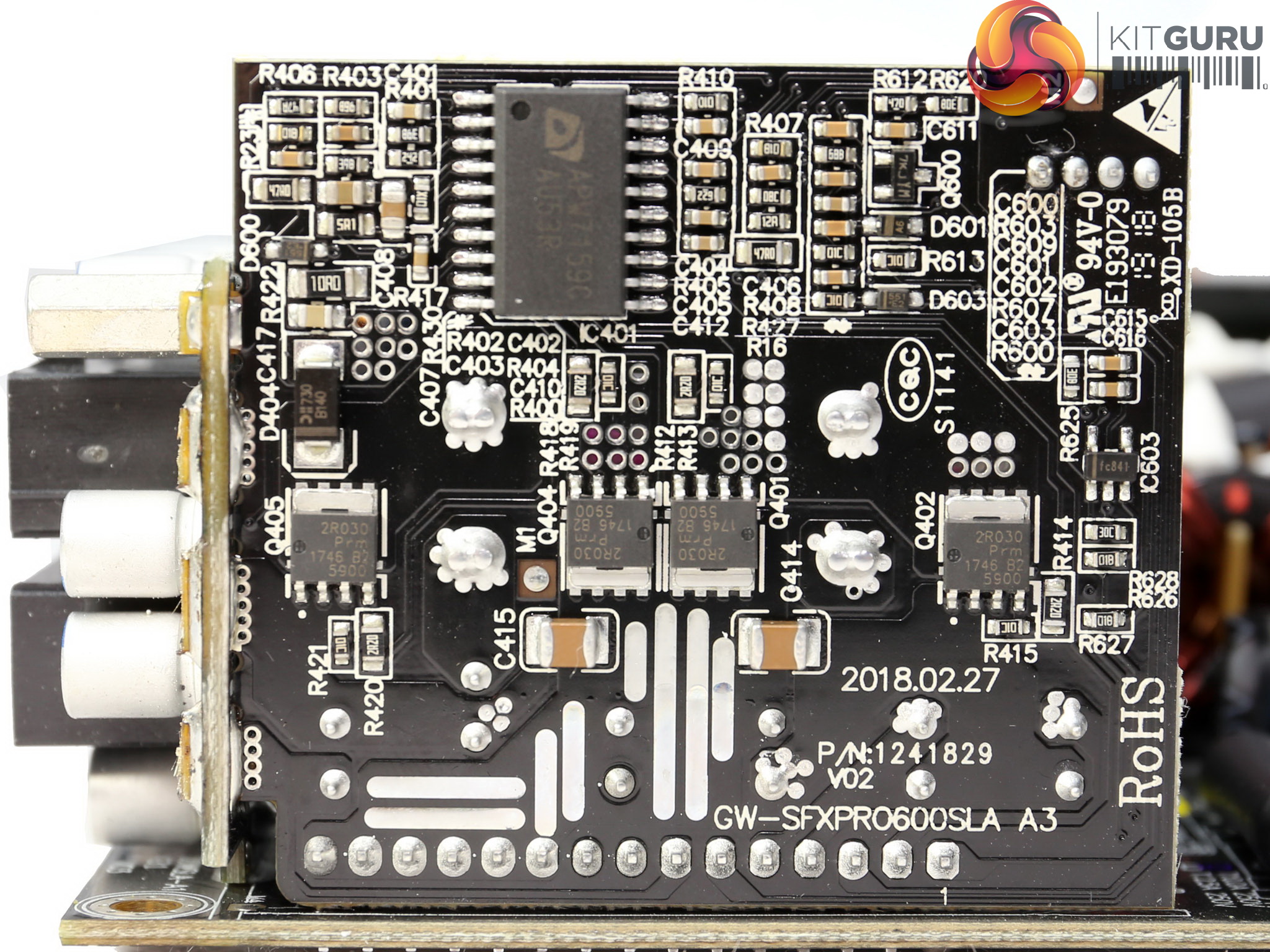
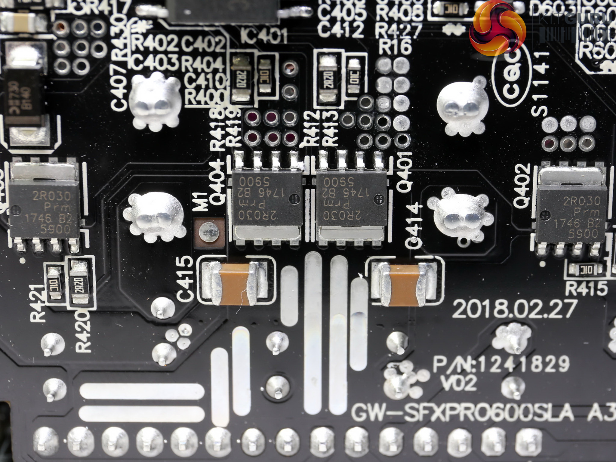
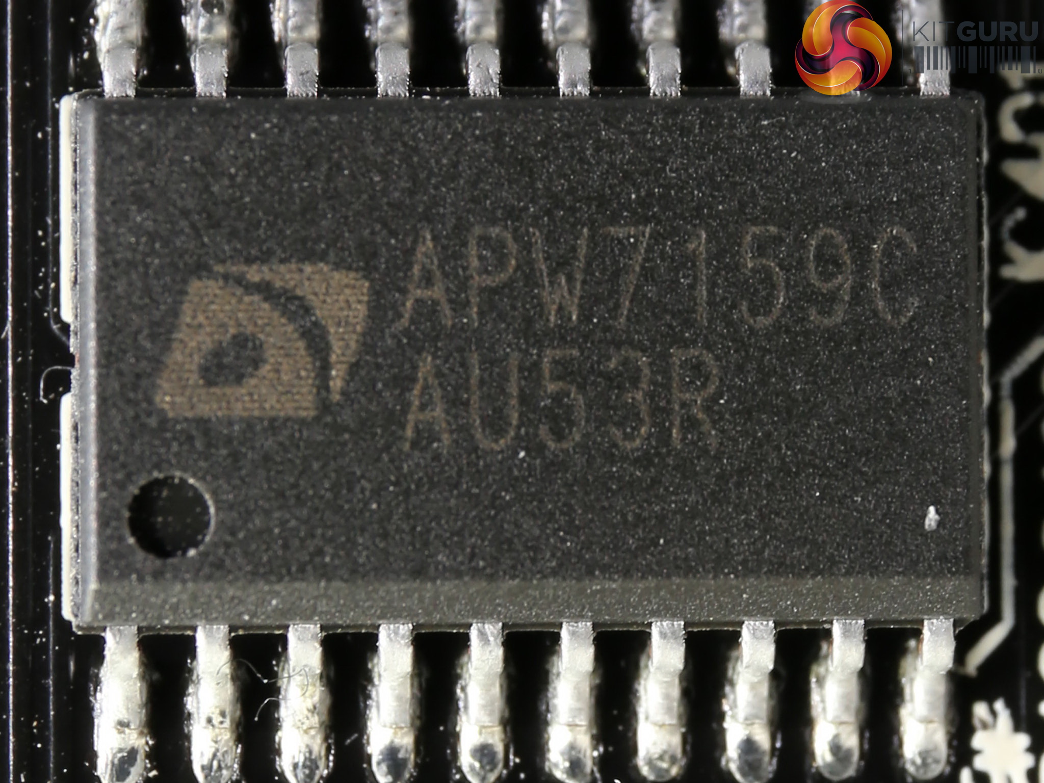
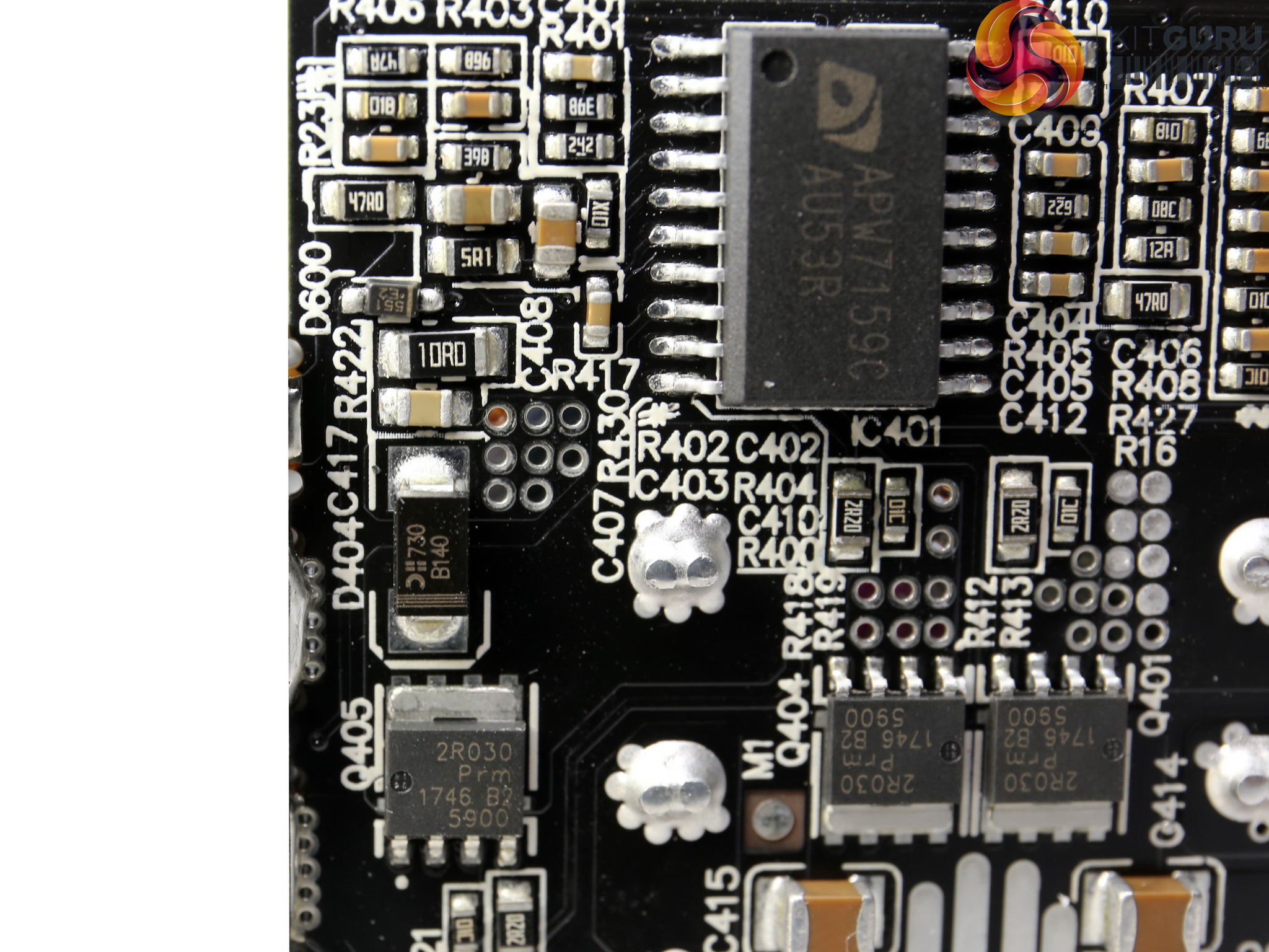
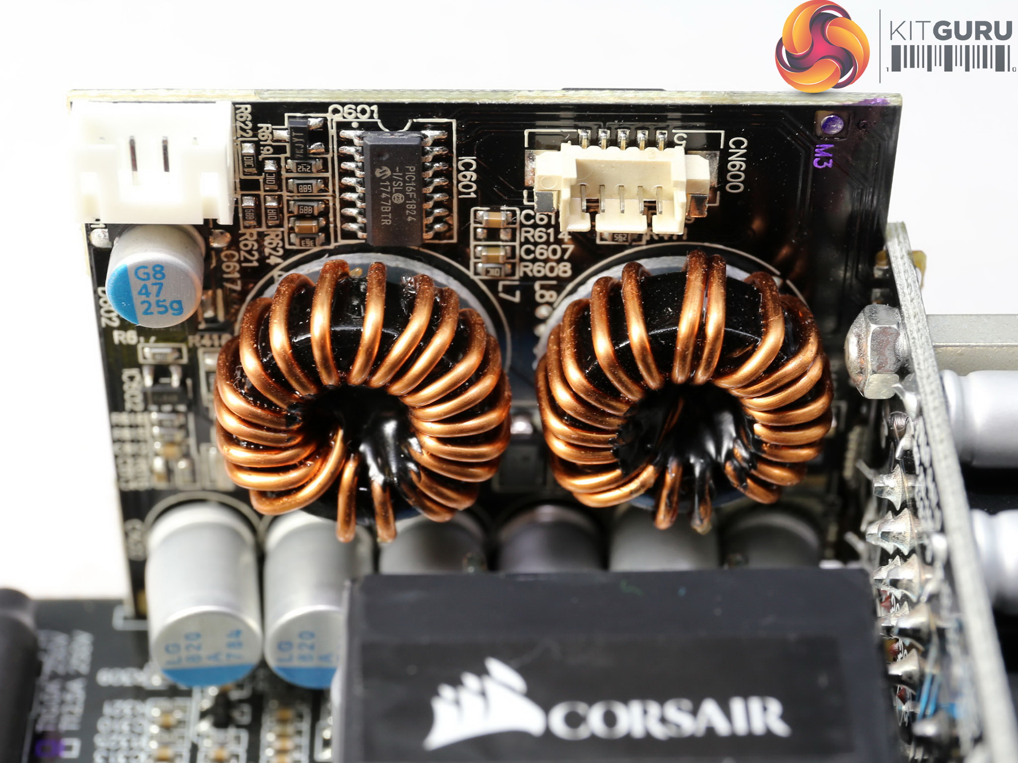
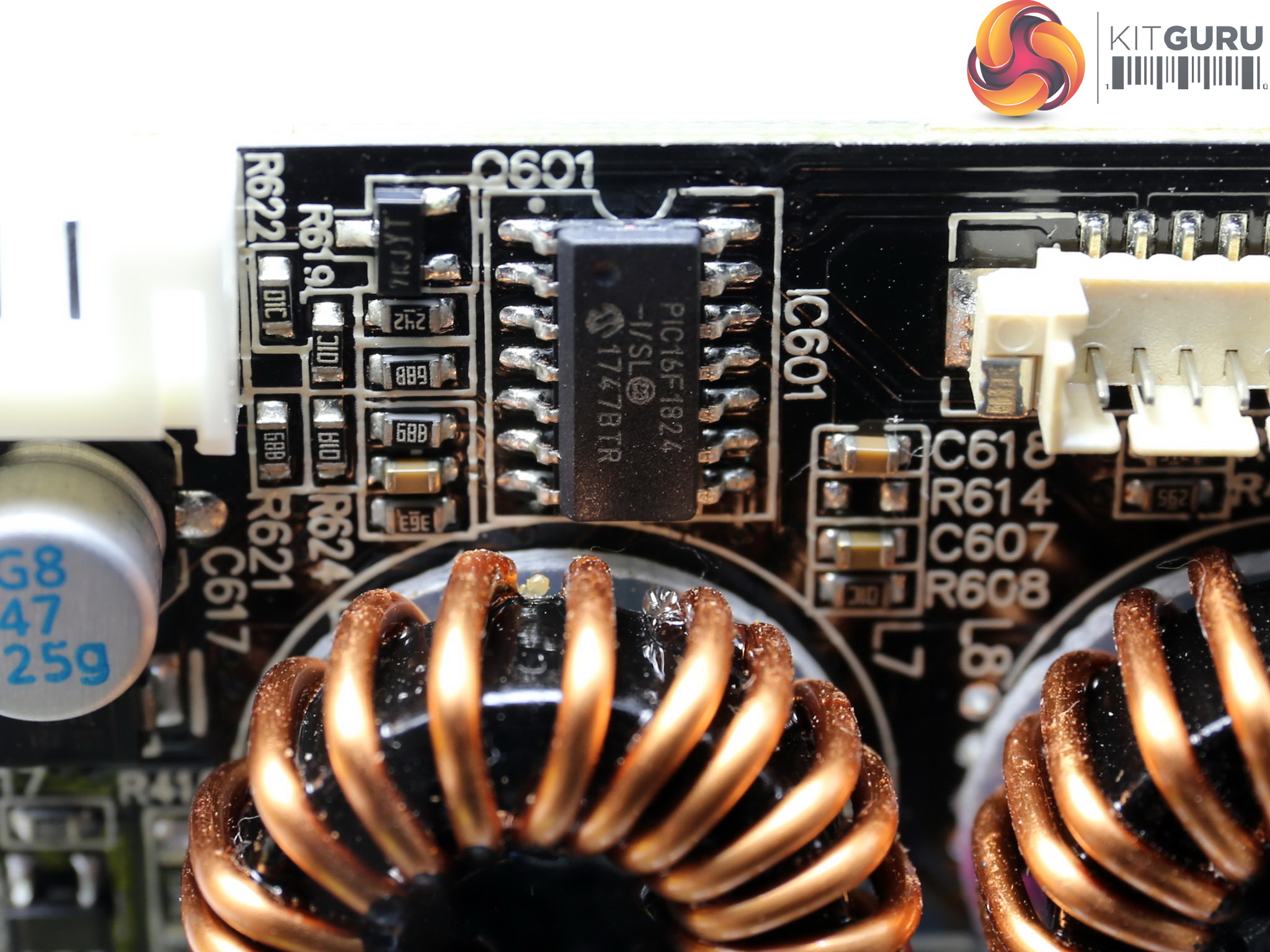
The voltage regulation modules that handle the minor rails share the same daughter-board with the fan control circuit. Four Nexperia PSMN2R0-30YL FETs are installed on this board and the common PWM controller is a Anpec APW7159C IC. The MCU that controls the fan's speed, through a PWM signal, is a PIC16F1824.
![]()
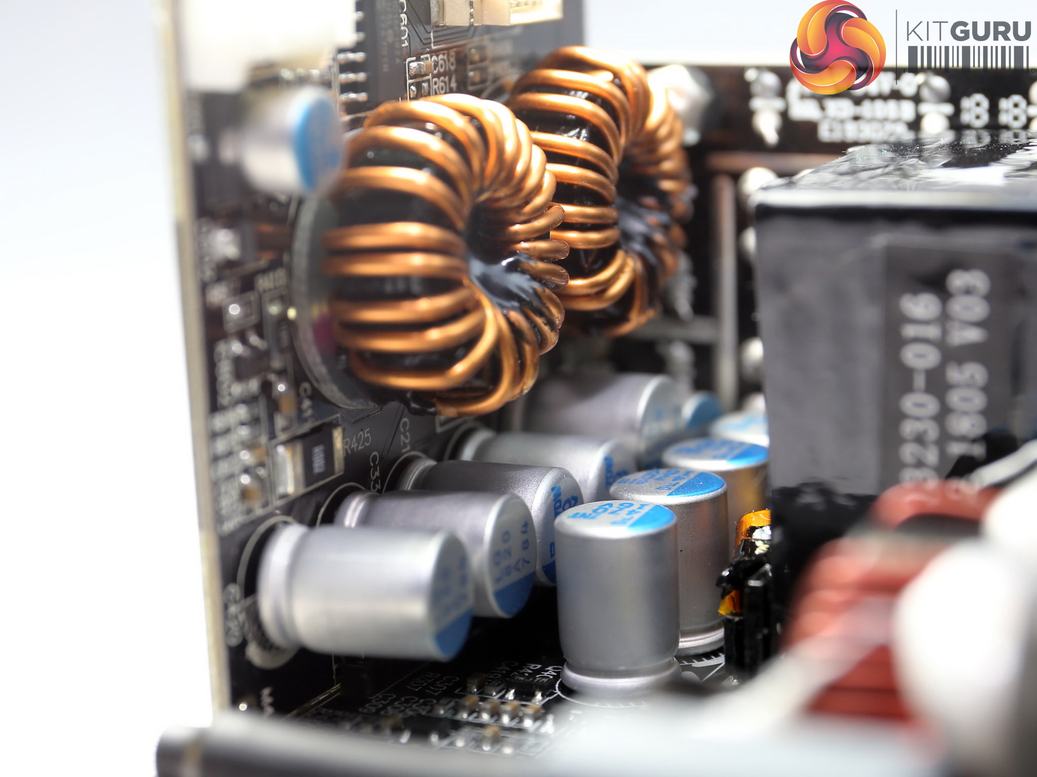
We only spot three electrolytic caps on the secondary side, with one of them belonging to the 5VSB circuit. The ripple filtering on all rails is mostly handled by polymer caps.
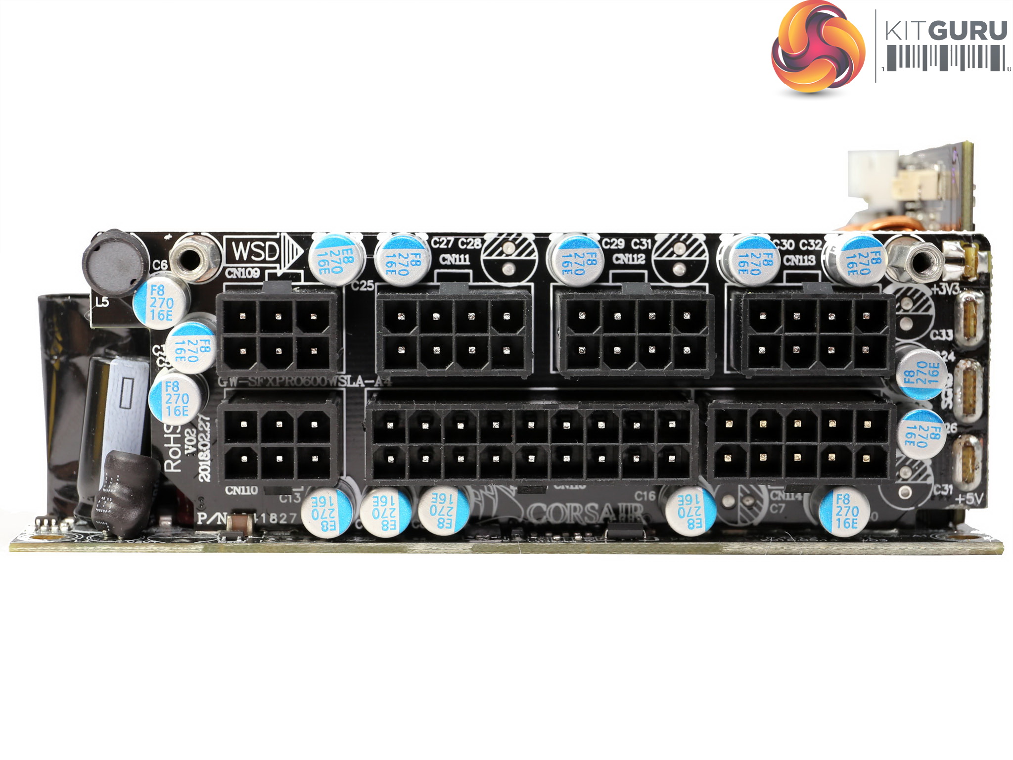
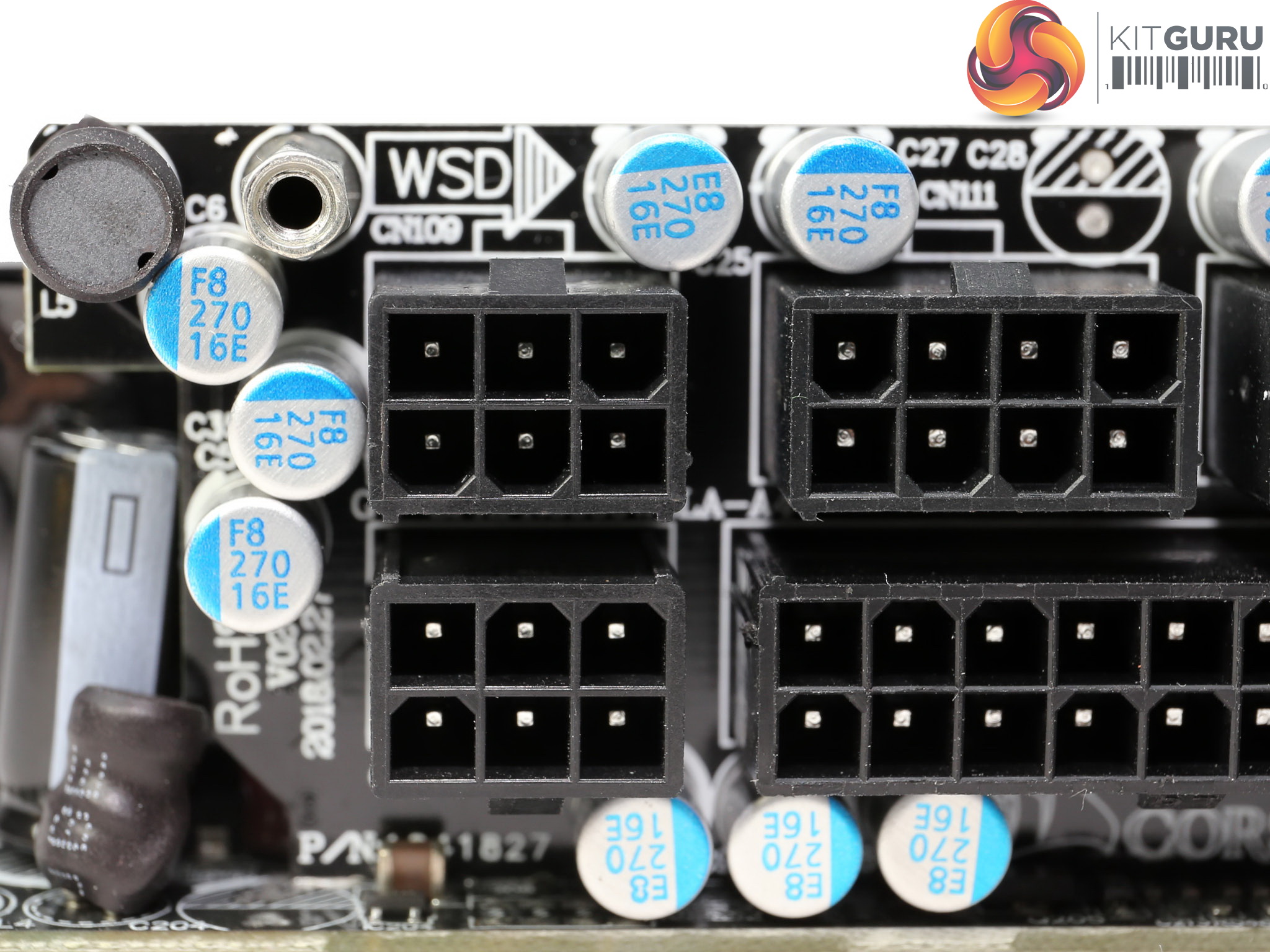
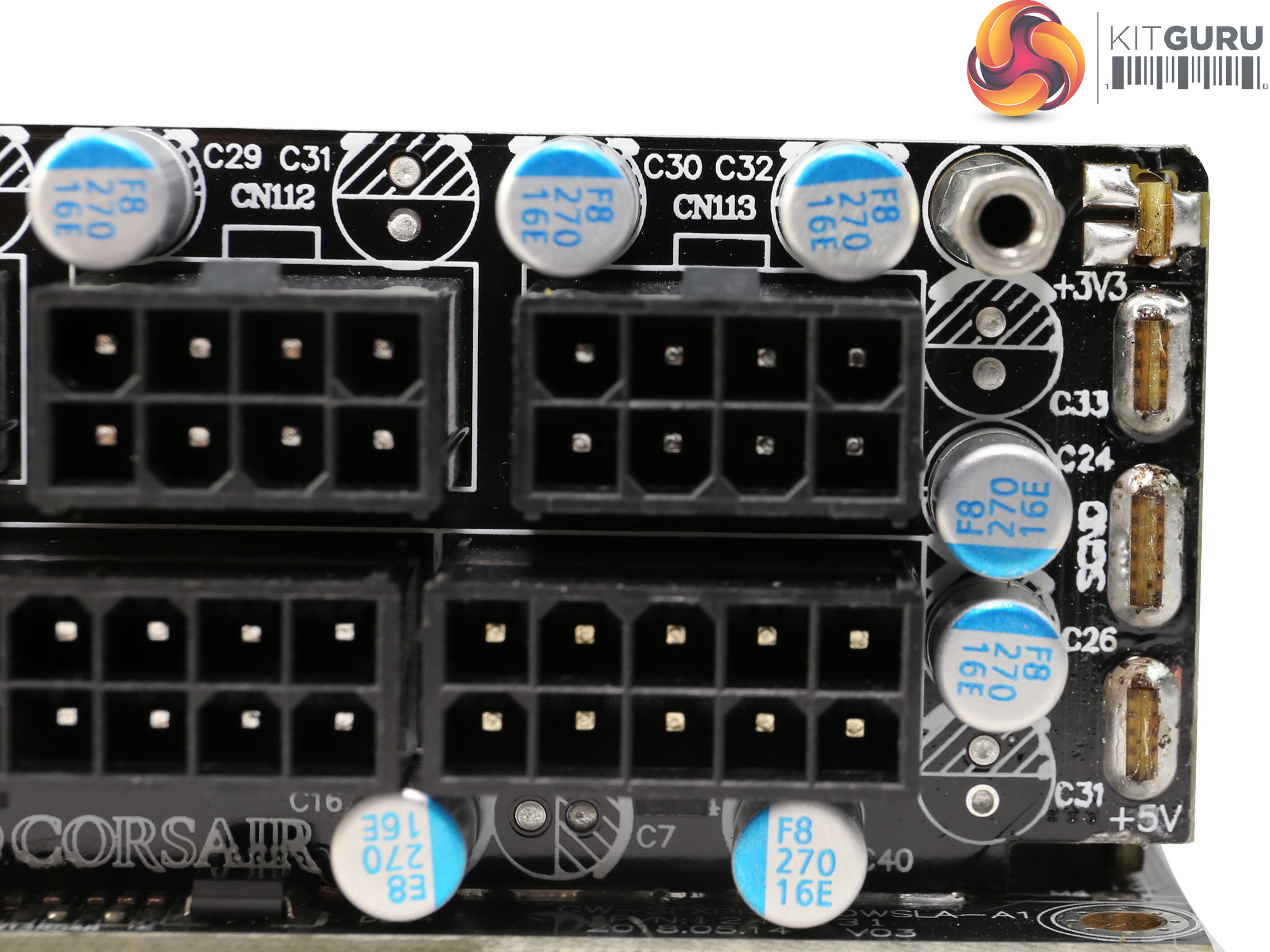
We find a great number of polymer caps on the modular board, while at its back there are also a lot of MLCC caps, for high frequency ripple filtering.
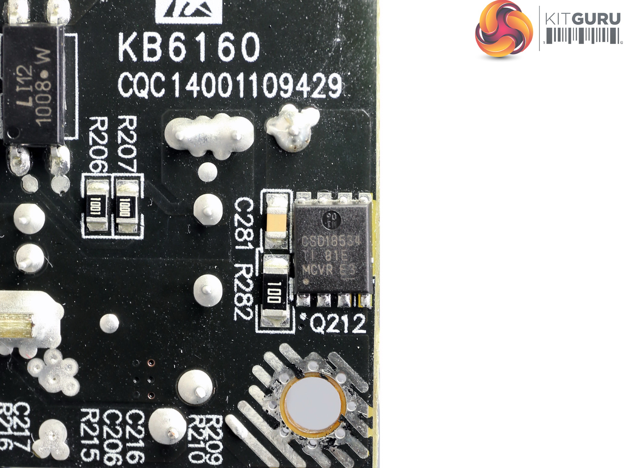
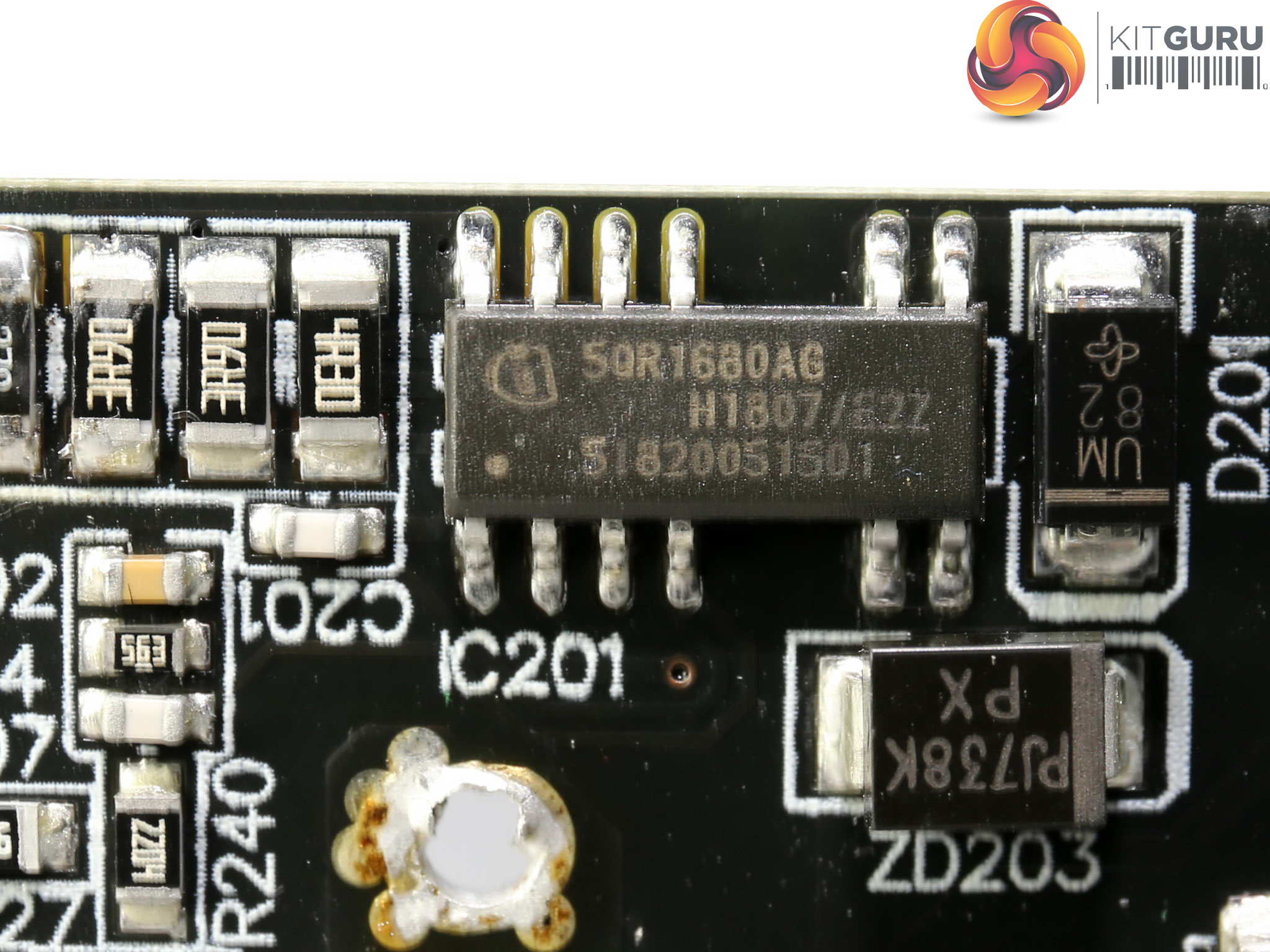
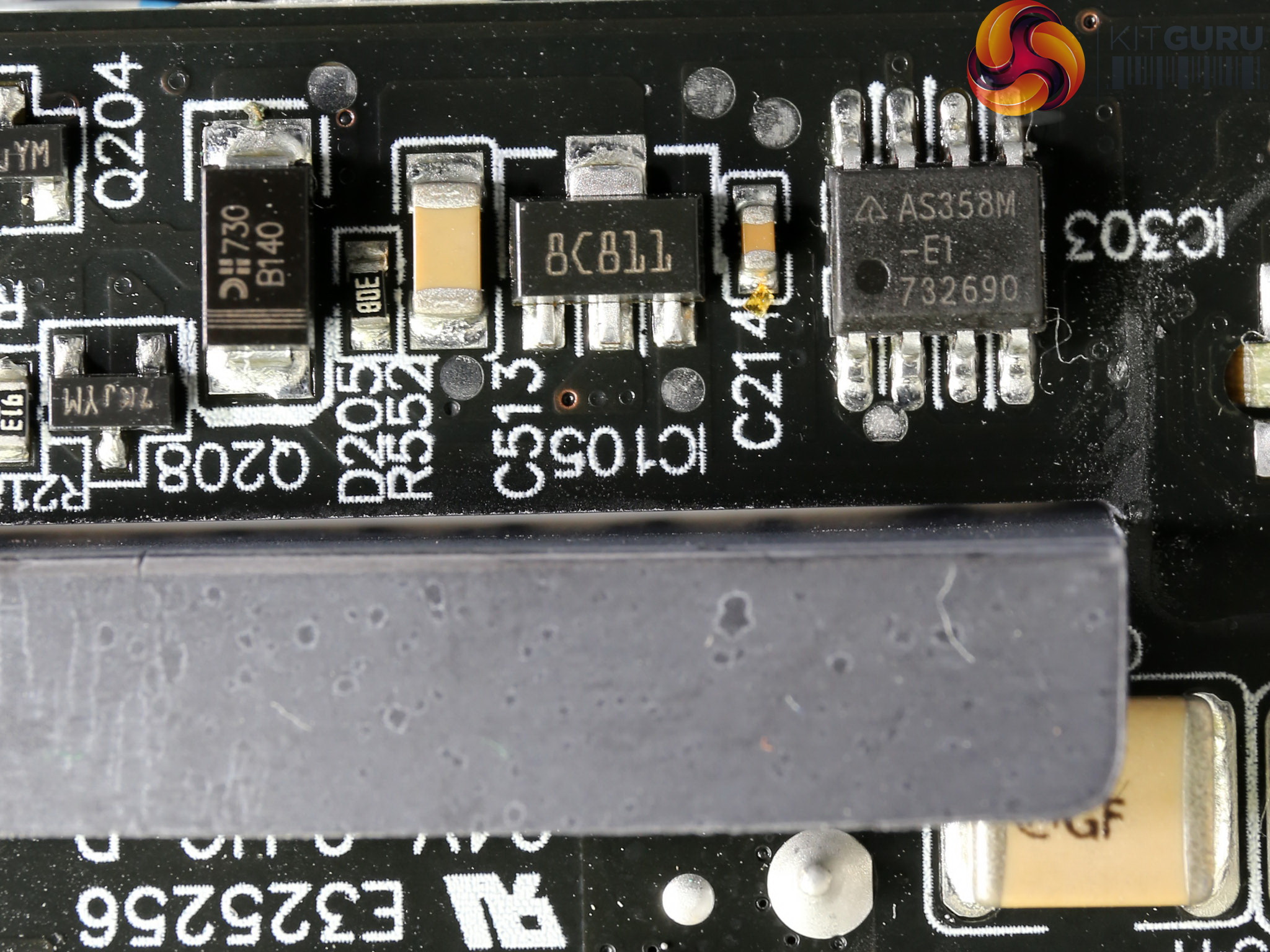
The 5VSB circuit includes a CSD18534 FET and its PWM controller is a Infineon ICE5QR1680AG.
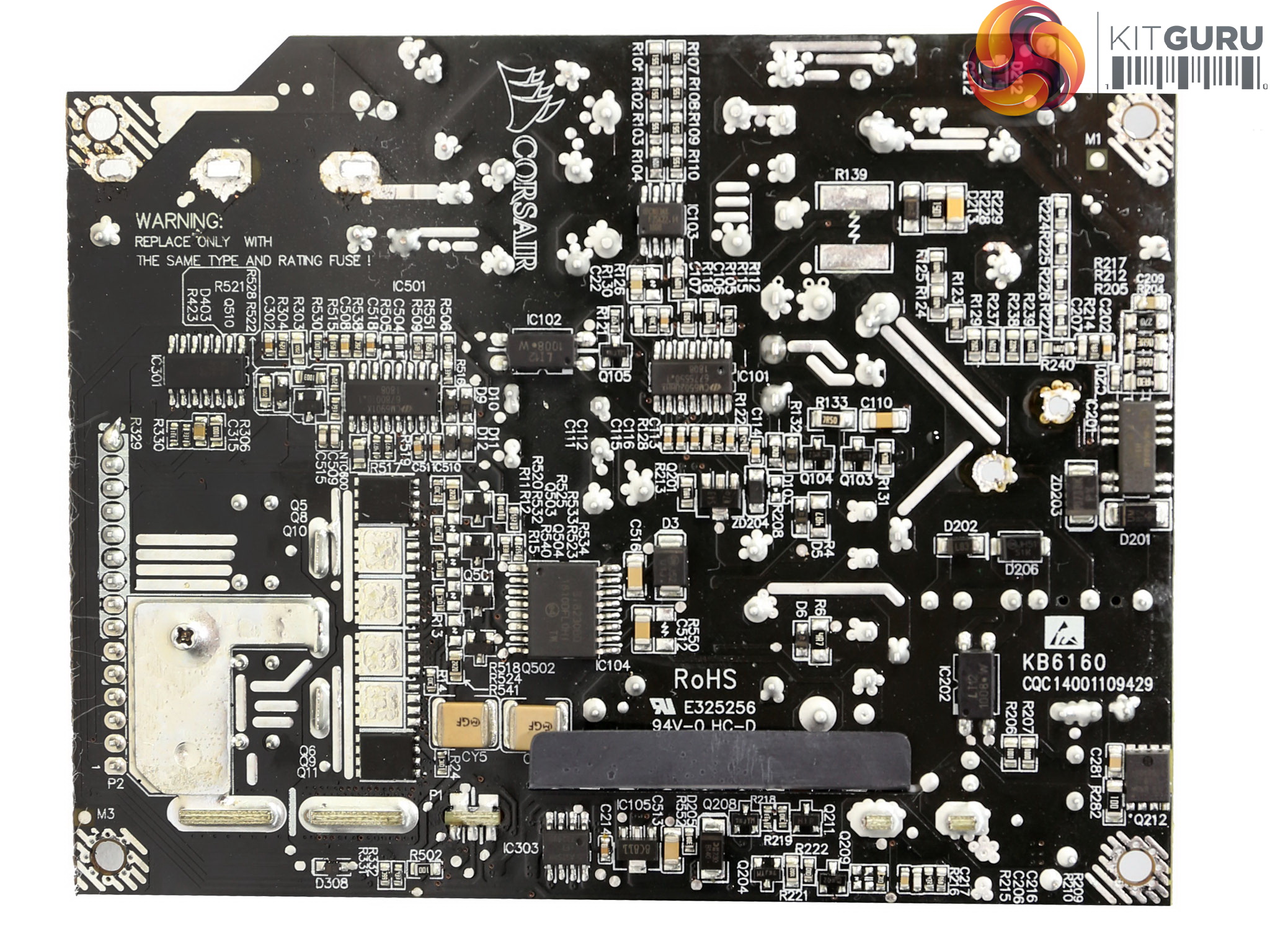
The soldering quality is very good, as we expect in a high-end product like this one.
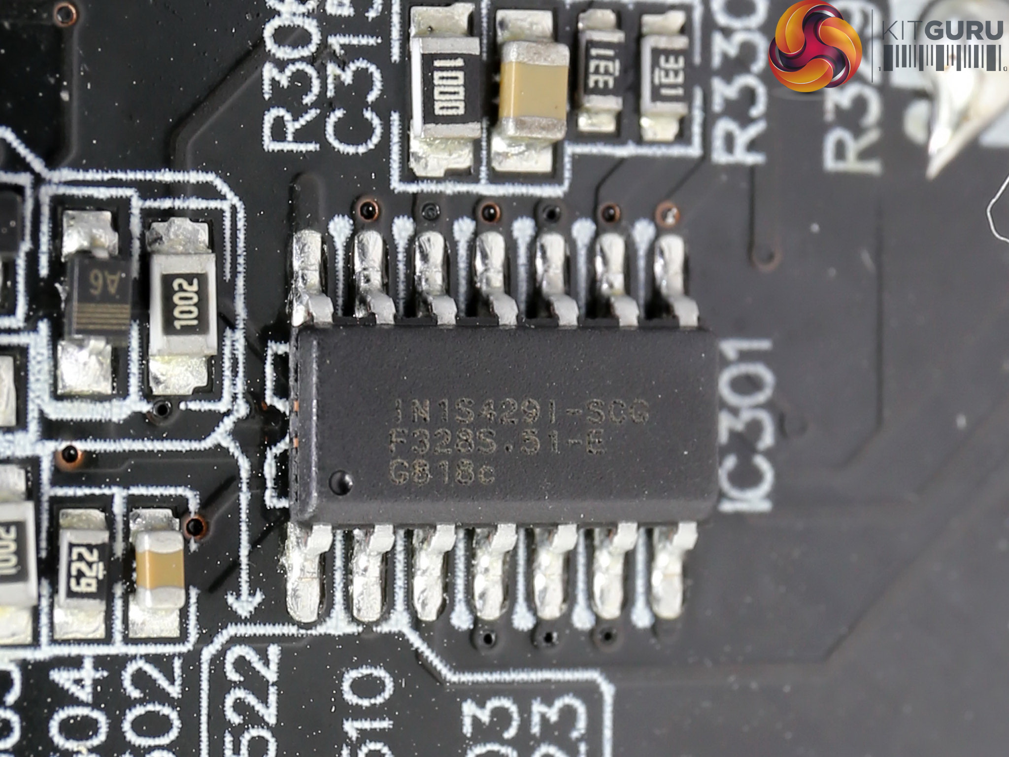
The supervisor IC is a IN1S429I -SCG, for which we couldn't find any information on the internet.
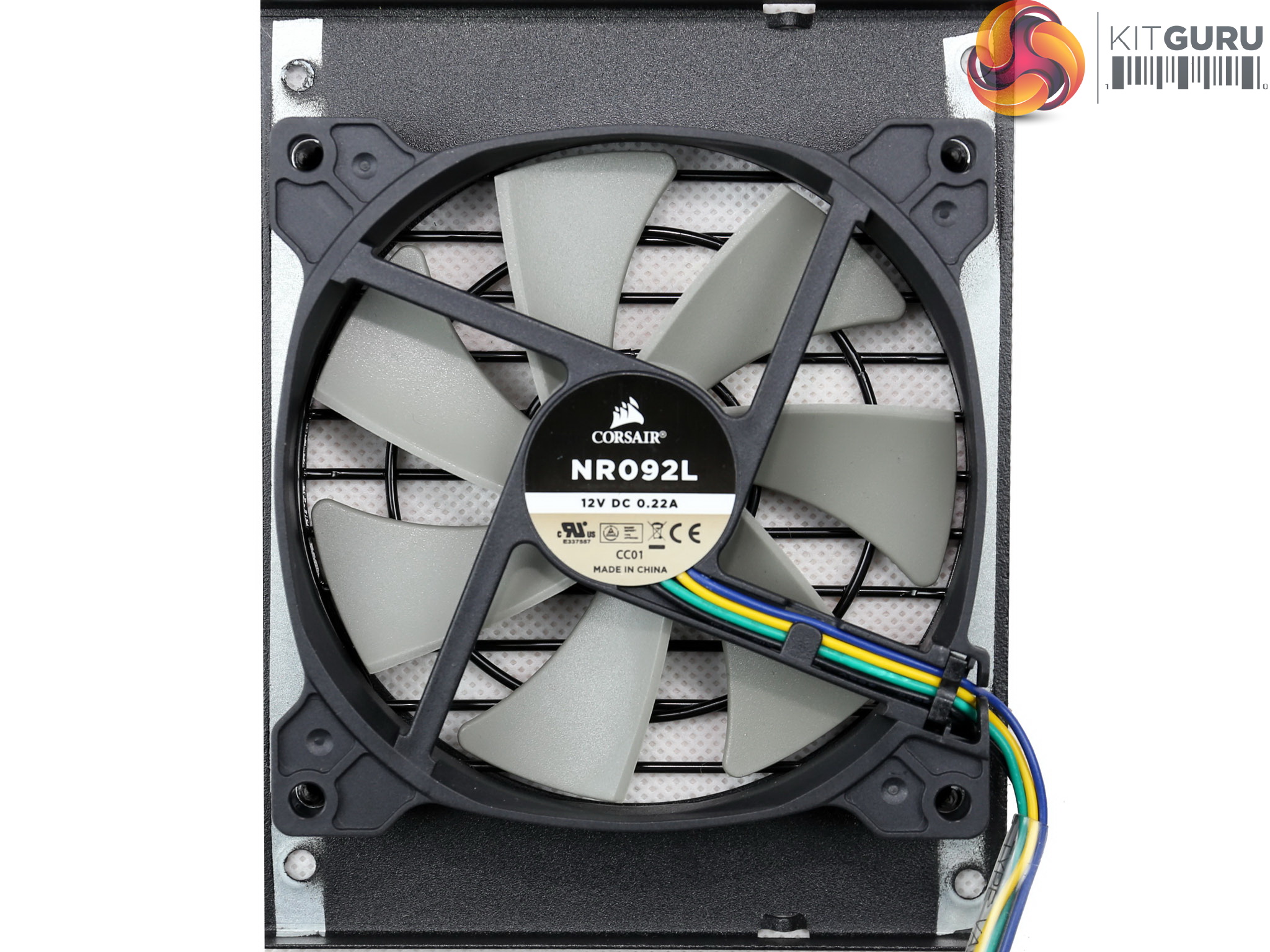
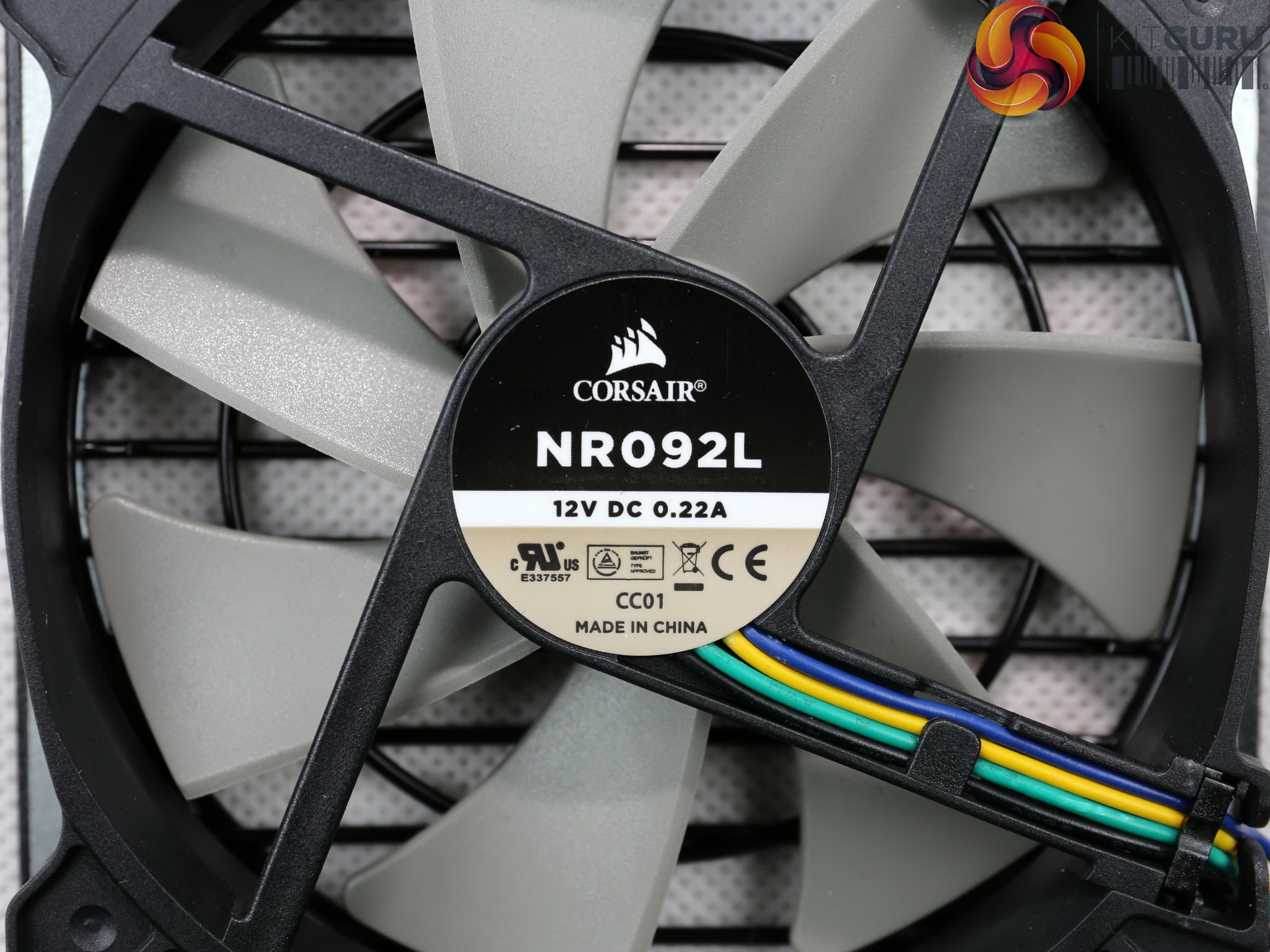
The cooling fan's model number is NR092L and it uses a rifle bearing. Thanks to the optimized design and the relaxed speed profile which is controlled through a PWM signal, the fan doesn't make much noise.
The semi-passive operation also plays a significant role in this unit's quiet operation, however it would be nice if it could be deactivated.
To learn more about our PSU tests and methodology, please check out How We Test Power Supply Units.
Primary Rails And 5VSB Load Regulation
Load Regulation testing is detailed here.
Hold-Up Time
Our hold-up time tests are described in detail here.
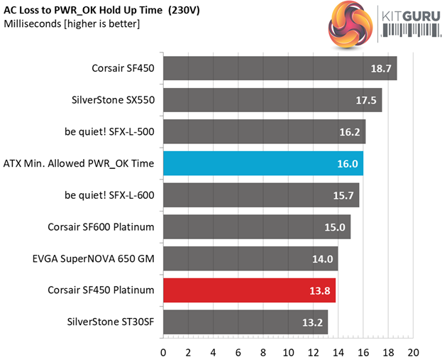
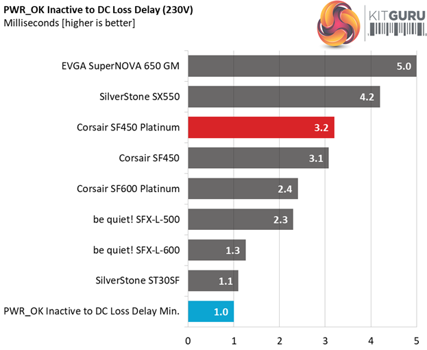
The oscilloscope screenshots that we took during the hold-up time measurements:
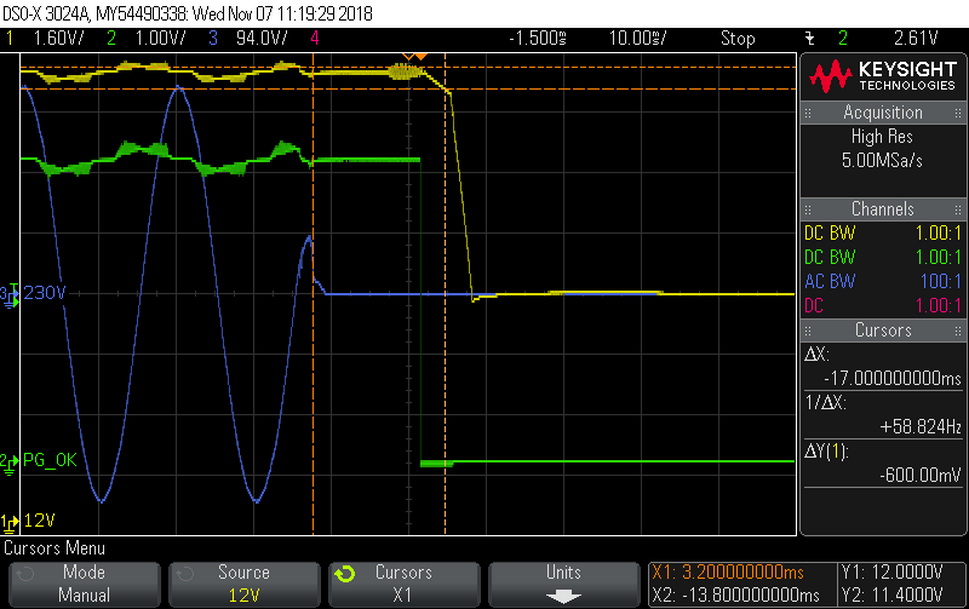
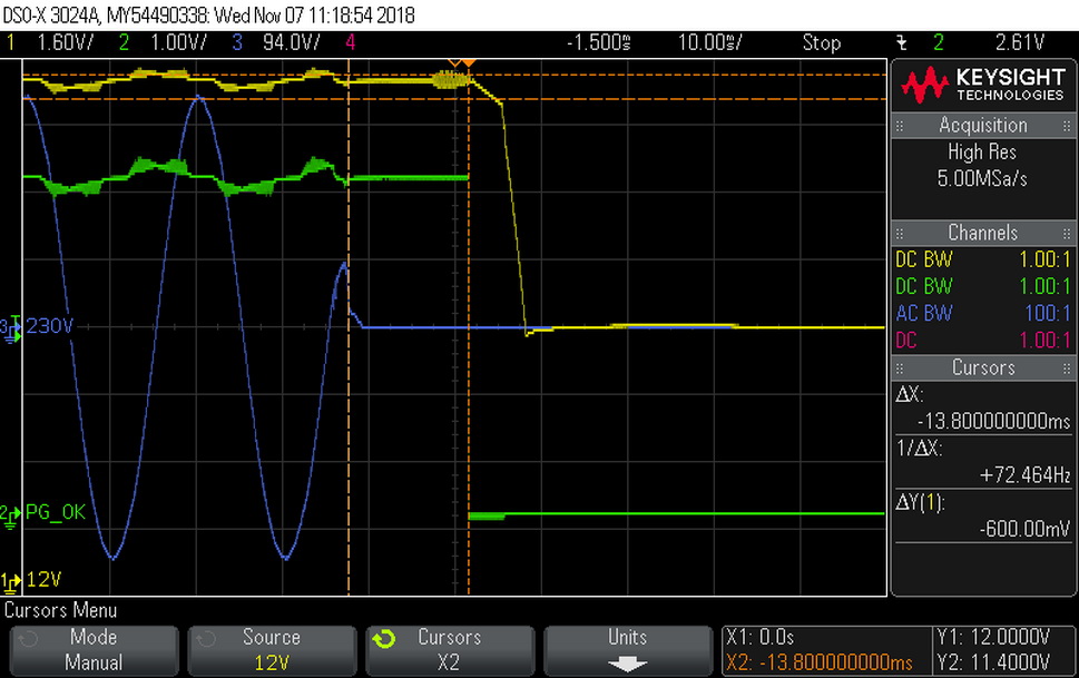
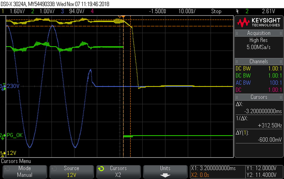
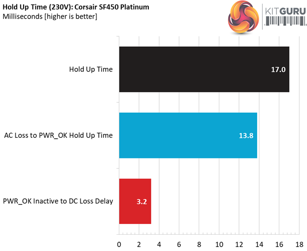
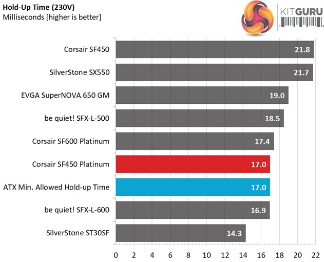
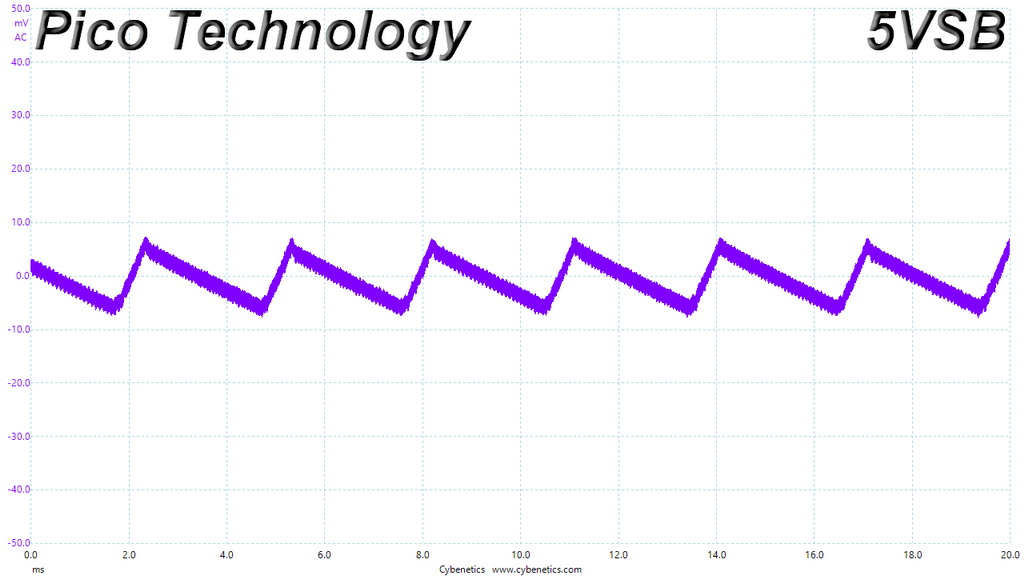
The hold-up time is right on spot at 17ms, however the power ok signal is shorter than 16ms. It is accurate at least. In the scope screenshots we notice a low frequency ripple pattern on the standby signal, which is identical to the oscillation of the +12V rail.
Inrush Current
For details on our inrush current testing, please click here.
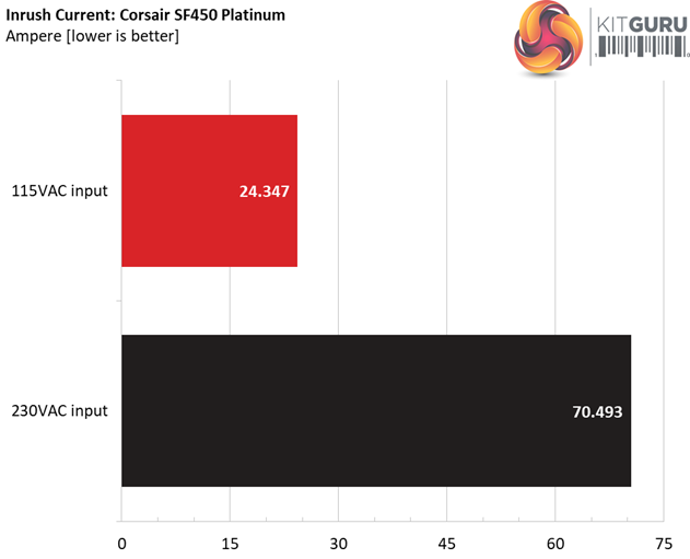
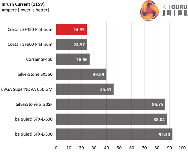
The inrush current might be low with 115V, but is on the high side with 230V.
Load Regulation And Efficiency Measurements
The first set of tests reveals the stability of the voltage rails and the SF450’s efficiency. The applied load equals (approximately) 10 to 110 percent of the power supplies maximum load in increments of 10 percentage points.
We conducted two additional tests.
During the first, we stressed the two minor rails (5V and 3.3V) with a high load, while the load at +12V was only 0.1A. This test reveals whether a power supply is compatible with Intel’s C6/C7 sleep states or not. In the second test, we determined the maximum load the +12V rail could handle with minimal load on the minor rails.
| Test # | 12V | 5V | 3.3V | 5VSB | DC/AC (Watts) | Efficiency | Fan Speed (RPM) | PSU Noise (dB[A]) | Temps (In/Out) | PF/AC Volts |
| 1 | 1.925A | 1.981A | 1.969A | 0.995A | 44.859 | 84.997% | 0 | <6.0 | 44.32°C | 0.870 |
| 12.081V | 5.051V | 3.350V | 5.026V | 52.777 | 39.82°C | 115.05V | ||||
| 2 | 4.841A | 2.971A | 2.955A | 1.195A | 89.381 | 89.567% | 0 | <6.0 | 45.61°C | 0.937 |
| 12.080V | 5.051V | 3.349V | 5.021V | 99.792 | 40.51°C | 115.05V | ||||
| 3 | 8.152A | 3.467A | 3.435A | 1.396A | 134.485 | 91.120% | 0 | <6.0 | 46.63°C | 0.960 |
| 12.080V | 5.050V | 3.348V | 5.015V | 147.591 | 41.19°C | 115.05V | ||||
| 4 | 11.467A | 3.963A | 3.944A | 1.597A | 179.685 | 91.657% | 1311 | 13.8 | 41.86°C | 0.974 |
| 12.076V | 5.049V | 3.347V | 5.010V | 196.040 | 47.86°C | 115.05V | ||||
| 5 | 14.450A | 4.953A | 4.931A | 1.799A | 224.988 | 91.785% | 1393 | 15.7 | 42.15°C | 0.981 |
| 12.075V | 5.048V | 3.346V | 5.004V | 245.126 | 48.48°C | 115.05V | ||||
| 6 | 17.362A | 5.946A | 5.918A | 2.001A | 269.486 | 91.049% | 1547 | 18.9 | 42.66°C | 0.877 |
| 12.077V | 5.047V | 3.345V | 4.998V | 295.980 | 49.93°C | 115.05V | ||||
| 7 | 20.342A | 6.938A | 6.906A | 2.204A | 314.785 | 91.078% | 1728 | 22.0 | 43.00°C | 0.987 |
| 12.077V | 5.046V | 3.345V | 4.993V | 345.623 | 50.83°C | 115.04V | ||||
| 8 | 23.326A | 7.931A | 7.894A | 2.407A | 360.106 | 90.707% | 1934 | 25.3 | 43.94°C | 0.989 |
| 12.076V | 5.046V | 3.344V | 4.987V | 396.998 | 52.40°C | 115.04V | ||||
| 9 | 26.707A | 8.427A | 8.376A | 2.408A | 405.004 | 90.376% | 2174 | 28.3 | 44.52°C | 0.990 |
| 12.075V | 5.045V | 3.343V | 4.984V | 448.130 | 53.55°C | 115.04V | ||||
| 10 | 30.025A | 8.926A | 8.887A | 2.510A | 449.706 | 89.918% | 2706 | 34.5 | 45.67°C | 0.991 |
| 12.073V | 5.044V | 3.341V | 4.980V | 500.128 | 55.86°C | 115.04V | ||||
| 11 | 33.744A | 8.926A | 8.892A | 2.512A | 494.517 | 89.481% | 3184 | 38.7 | 46.88°C | 0.992 |
| 12.070V | 5.043V | 3.341V | 4.978V | 552.651 | 57.67°C | 115.04V | ||||
| CL1 | 0.138A | 12.002A | 11.999A | 0.000A | 102.476 | 86.890% | 742 | 6.5 | 42.21°C | 0.948 |
| 12.095V | 5.050V | 3.350V | 5.028V | 117.938 | 48.51°C | 115.05V | ||||
| CL2 | 37.509A | 1.002A | 1.001A | 1.000A | 466.102 | 90.568% | 2648 | 34.3 | 45.90°C | 0.991 |
| 12.069V | 5.046V | 3.342V | 5.005V | 514.642 | 55.83°C | 115.04V |
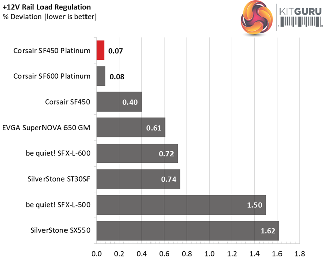
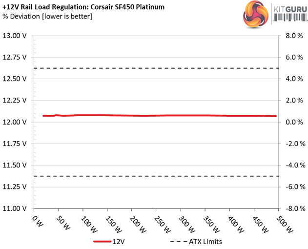
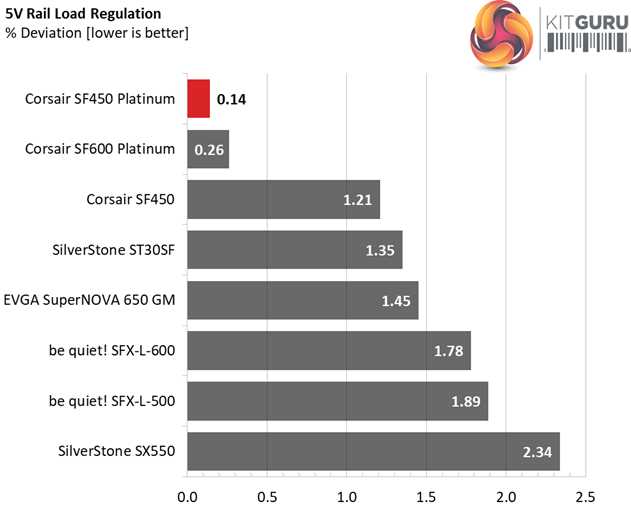
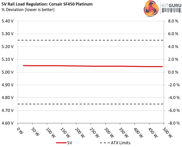
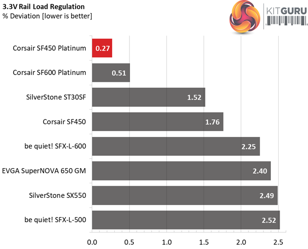
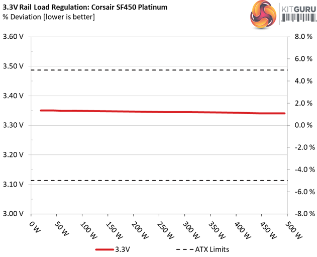
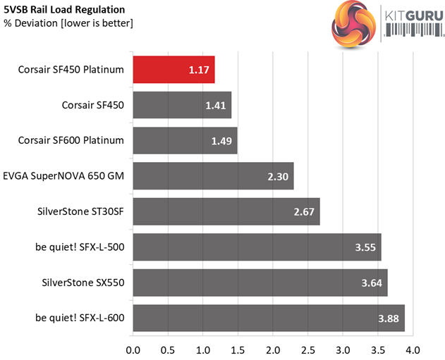
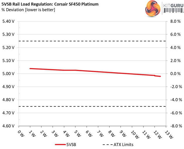
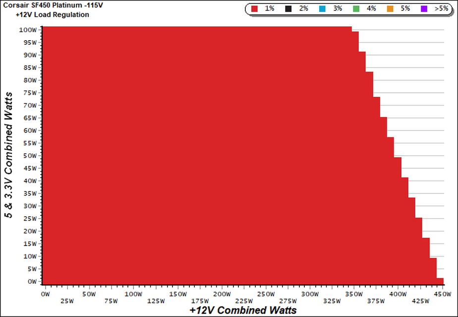
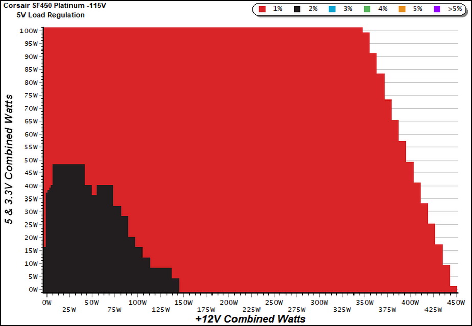
The load regulation is super tight on all rails. Great Wall managed to greatly improve the original, Gold platform, in this section.
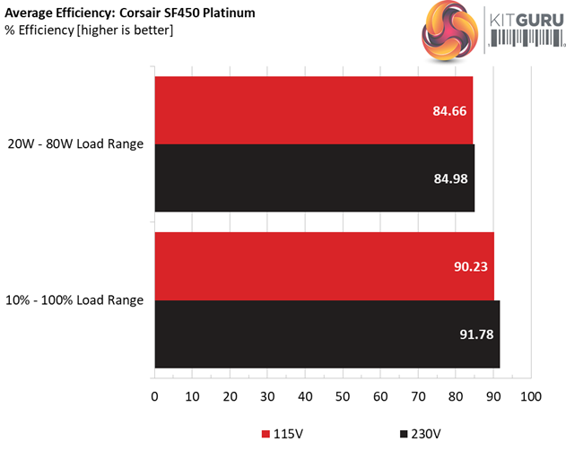
With 20% and 50% load levels the SF450 is not able to reach the required efficiency levels that the 80 PLUS Platinum standard asks for, while with full load it is close to the Titanium mark of 90%. We should stress that we conduct those tests at a very high ambient, contrary to the 80 PLUS organisation, so it is natural to measure lower efficiency levels. Under lower temperatures the efficiency will be increased in all cases.
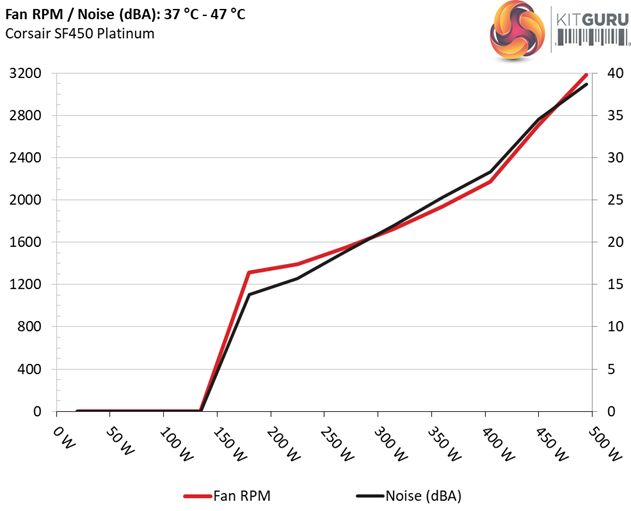
The fan profile is highly relaxed and we have to push the unit very hard, and beyond its official limits, to make the fan spin at close to 3200 RPM where its output noise doesn't breach the 40 dB(A) mark.
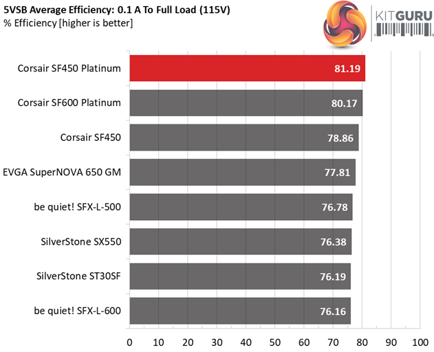
Efficiency
Our efficiency testing procedure is detailed here.
Using results from the previous page, we plotted a chart showing the SF450’s efficiency at low loads, and loads from 10 to 110 percent of its maximum-rated capacity.
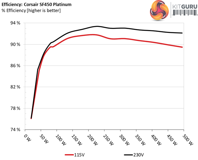
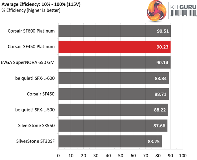
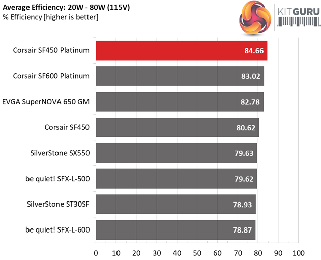
Under normal loads the SF450 Platinum loses only to its big brother, the SF600 Platinum, while with light loads it clearly takes the lead.
Efficiency At Low Loads
In the following tests, we measure the SF450's efficiency at loads significantly lower than 10 percent of its maximum capacity (the lowest load the 80 PLUS standard measures). The loads we dial are 20, 40, 60, and 80W. This is important for representing when a PC is idle, with power-saving features turned on.
| Test # | 12V | 5V | 3.3V | 5VSB | DC/AC (Watts) | Efficiency | Fan Speed (RPM) | PSU Noise (dB[A]) | PF/AC Volts |
| 1 | 1.198A | 0.495A | 0.478A | 0.199A | 19.568 | 76.102% | 0 | <6.0 | 0.791 |
| 12.074V | 5.052V | 3.350V | 5.039V | 25.713 | 115.05V | ||||
| 2 | 2.458A | 0.991A | 0.983A | 0.397A | 39.977 | 85.137% | 0 | <6.0 | 0.858 |
| 12.075V | 5.051V | 3.350V | 5.035V | 46.956 | 115.05V | ||||
| 3 | 3.649A | 1.486A | 1.461A | 5.031A | 59.458 | 87.884% | 0 | <6.0 | 0.899 |
| 12.075V | 5.051V | 3.349V | 5.031V | 67.655 | 115.05V | ||||
| 4 | 4.907A | 1.981A | 1.970A | 0.796A | 79.867 | 89.501% | 0 | <6.0 | 0.930 |
| 12.077V | 5.051V | 3.349V | 5.027V | 89.236 | 115.05V |
This platforms efficiency under light loads is nothing less but impressive! Moreover, the fan doesn't spin at all during those tests so the output noise is minimal.
5VSB Efficiency
The ATX specification (revision 1.4), along with CEC, ErP Lot 3 2014 and ErP Lot 6 2010/2013, states that the 5VSB standby supply efficiency should be as high as possible, recommending 75 percent or higher with 550mA, 1A, and 1.5A of load.
The supply should also achieve higher than 75% efficiency at 5VSB under full load, or with 3A if its max current output on this rail is higher than 3A.
We take six measurements: one each at 100, 250, 550, 1000, and 1500mA, and one with the full load the 5VSB rail can handle.
| Test # | 5VSB | DC/AC (Watts) |
Efficiency | PF/AC Volts |
| 1 | 0.100A | 0.505 | 71.530% | 0.260 |
| 5.042V | 0.706 | 115.05V | ||
| 2 | 0.250A | 1.260 | 83.610% | 0.341 |
| 5.040V | 1.507 | 115.05V | ||
| 3 | 0.550A | 2.771 | 85.288% | 0.401 |
| 5.037V | 3.249 | 115.04V | ||
| 4 | 1.000A | 5.032 | 85.332% | 0.441 |
| 5.031V | 5.897 | 115.05V | ||
| 5 | 1.500A | 7.538 | 83.905% | 0.463 |
| 5.025V | 8.984 | 115.04V | ||
| 6 | 2.500A | 12.532 | 84.300% | 0.489 |
| 5.012V | 14.866 | 115.04V |
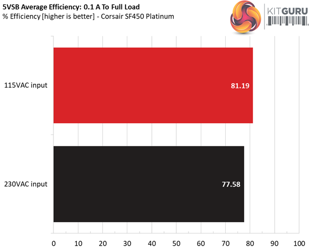
Great Wall vastly improved the efficiency of the 5VSB rail. The new SF Platinum models easily beat the competition and they are able to put to shame as well, many high-end ATX offerings. Unfortunately not many manufacturers pay attention to this rail's efficiency, so it is great to see such designs.
Power Consumption In Idle And Standby
In the table below, you’ll find the power consumption and voltage values of all rails (except -12V) when the PSU is idle (powered on, but without any load on its rails), and the power consumption when the unit is in standby mode (without any load, at 5VSB).
| Mode | 12V | 5V | 3.3V | 5VSB | Watts | PF/AC Volts |
| Idle | 12.095V | 5.050V | 3.348V | 5.044V | 5.185 | 0.499 |
| 115.1V | ||||||
| Standby | 0.047 | 0.027 | ||||
| 115.1V | ||||||
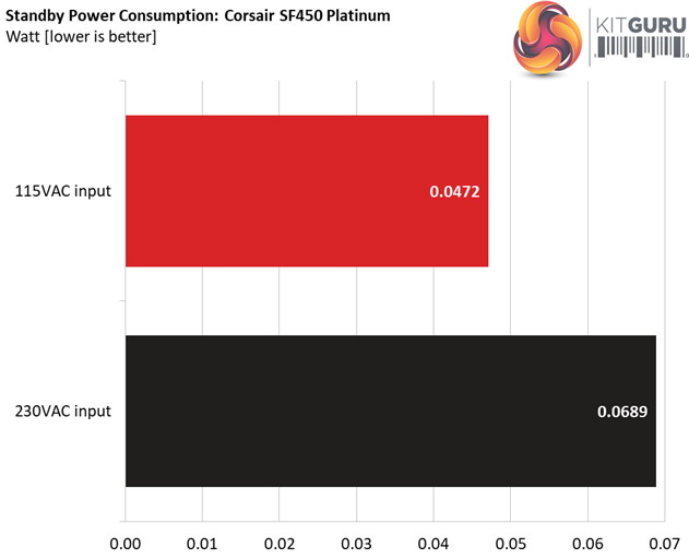
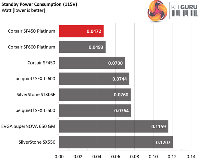
The energy needs in idle are kept at very low levels, with both voltage inputs that we apply.
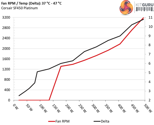
Fan RPM, Delta Temperature, And Output Noise
Our mixed noise testing is described in detail here.
The first chart below illustrates the cooling fan's speed (in RPM), and the delta between input and output temperature. The results were obtained at 37°C (98.6°F) to 47°C (116.6°F) ambient temperature.
The next chart shows the cooling fan's speed (again, in RPM) and output noise. We measure acoustics from one meter away, inside a hemi-anechoic chamber. Background noise inside the chamber is below 6 dB(A) during testing (it's actually much lower, but our sound meter’s microphone hits its floor), and the results are obtained with the PSU operating at 37°C (98.6°F) to 47°C (116.6°F) ambient temperature.
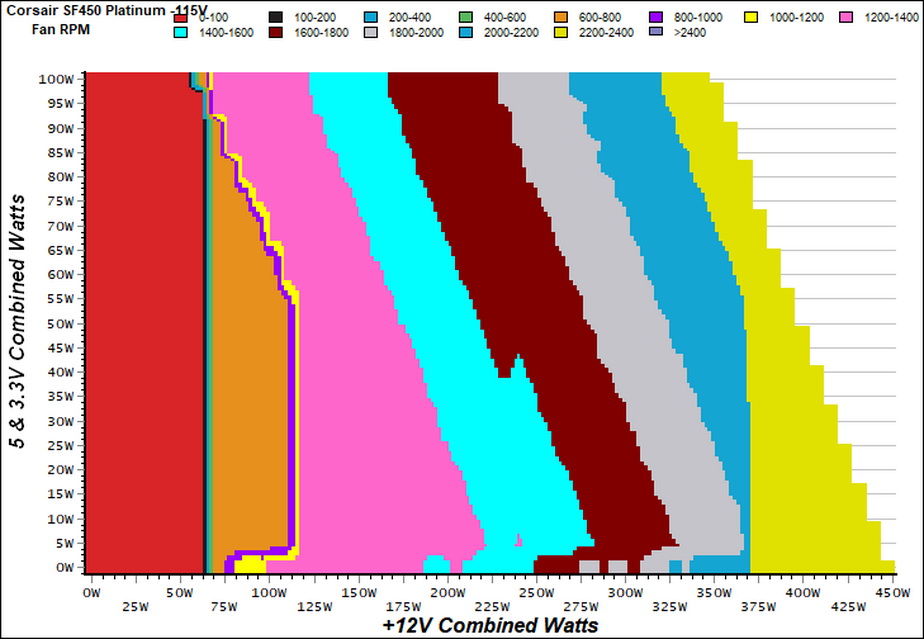
The following graphs illustrate the fan's output noise and speed over the PSU's operating range. The same conditions of the above graph apply to our measurements, though the ambient temperature is between 30°C (86°F) to 32°C (89.6°F).
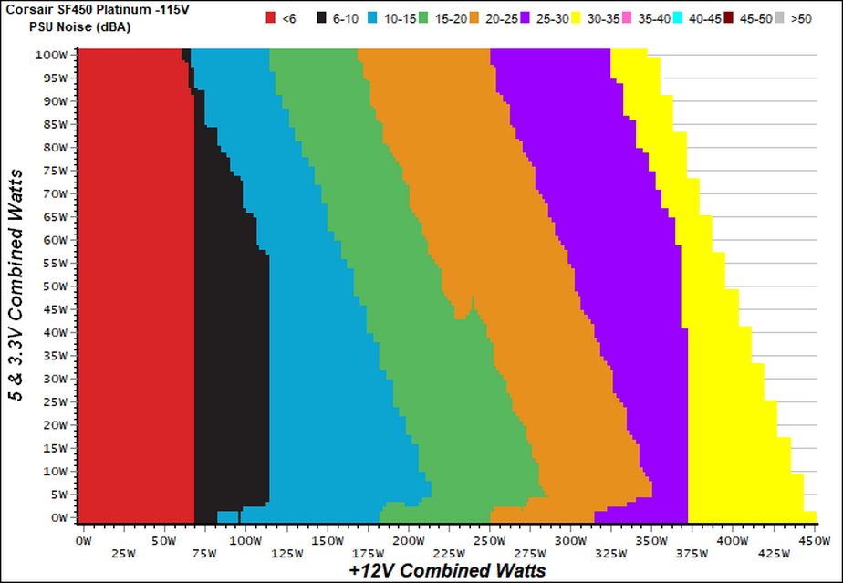
The semi-passive mode doesn't last long, since we heavily stress the minor rails during those tests and as it seems its operation also takes into account the temperatures of the DC-DC converters, that generate 5V and 3.3V.
It will need close to 375W load to make the power supply enter the 30-35 dB(A) zone, while with up to 250W at +12V the output noise stays below 20 dB(A).
Protection Features
Our protection features evaluation methodology is described in detail here.
|
Protection Features |
|
|
OCP |
12V: 50.6A (134.93%), 12.039V |
|
OPP |
622.9W (138.42%) |
|
OTP |
✓ (140°C @ Secondary side) |
|
SCP |
12V: ✓ |
|
PWR_OK |
Accurate (but lower than 16ms) |
|
NLO |
✓ |
|
SIP |
Surge: MOV |
With the only exception being the 3.3V rail, all the rest of the voltages have ideally configured over current protection triggering points. Moreover, the over temperature protection works well and gets activated once the temperature in the secondary side reaches 140°C.
The over power protection is set a little higher than the ideal 130% setting, however this is a low capacity supply so Corsair probably wanted to avoid any problems with power spikes, which can be generated by high-end GPUs.
There is short circuit protection on all rails and the power ok signal is accurate, but it is lower than 16ms which is the minimum period allowed by the ATX spec.
Finally, there is a Metal Oxide Varistor which protects not only the power supply but the whole system from power surges coming from the mains grid, while a NTC thermistor and bypass relay combo suppress the high inrush currents, during the PSU's start-up phase.
DC Power Sequencing
According to Intel’s most recent Power Supply Design Guide (revision 1.4) the +12V and 5V voltages must be equal or greater than the 3.3V rail’s output at all times, during the power-up and normal operation. For our first measurement, we turn the unit off and switch it back on without any load in any of the rails.
In the second test, we set the PSU to standby mode, dial full load and start it afterwards. In the last test, while the power supply is completely switched off (we cut off the power or switch the supply off through its power switch), we dial full load before restoring power.
The 3.3V rail is always lower than the 5V and 12V rails, so the power supply passes with success the required, by Intel's ATX spec, DC power sequencing tests.
Our cross-load tests are described in detail here.
To generate the following charts, we set our loaders to auto mode through our custom-made software before trying more than 1500 possible load combinations with the +12V, 5V, and 3.3V rails. The load regulation deviations in each of the charts below are calculated by taking the nominal values of the rails (12V, 5V, and 3.3V) as point zero. The ambient temperature is between at 30°C (86°F) to 32°C (89.6°F).
Load Regulation Charts
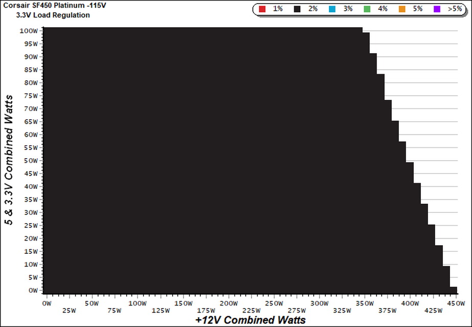
Efficiency Chart
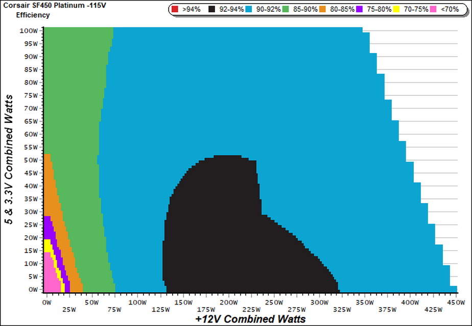
For a quite large region the SF unit delivers more than 92% efficiency. We usually meet such high efficiency levels in 80 PLUS Titanium and ETA-A+ certified PSUs.
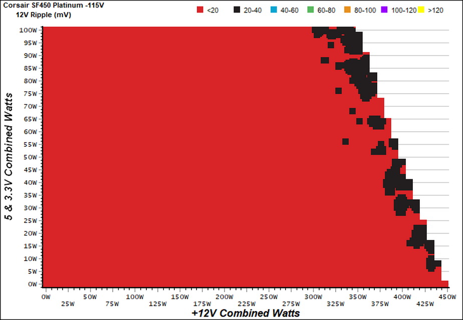
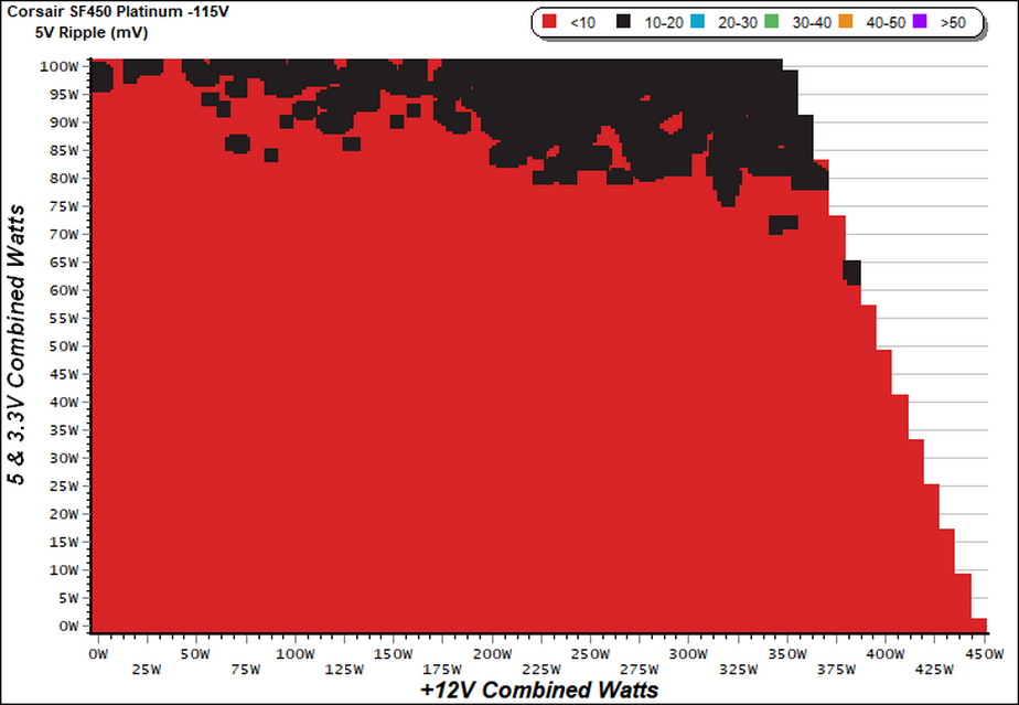
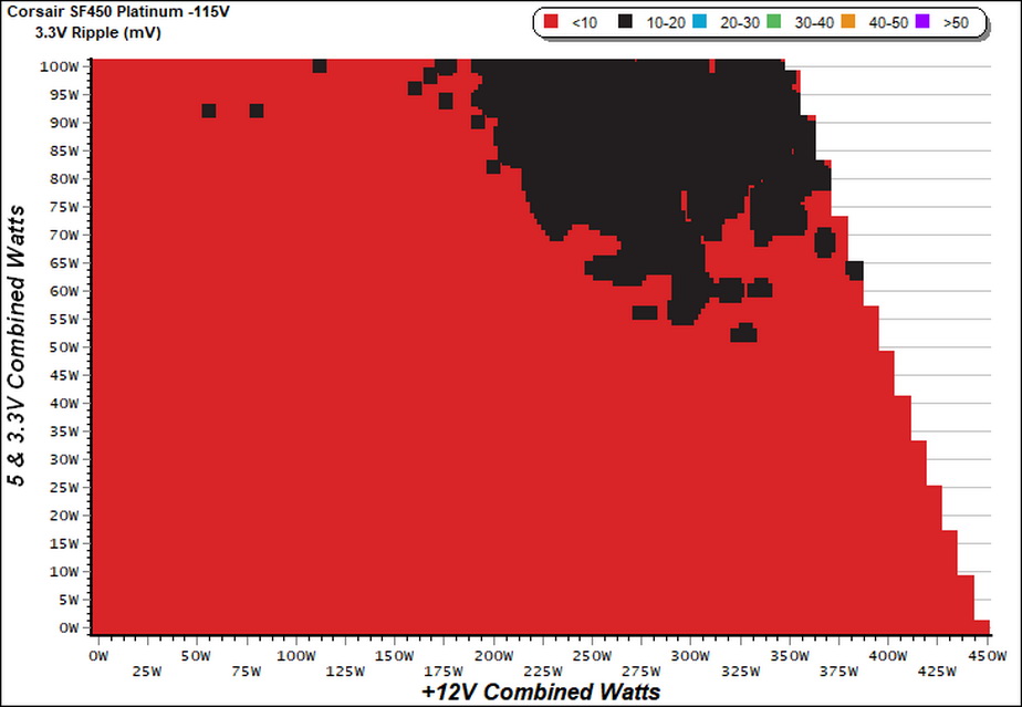
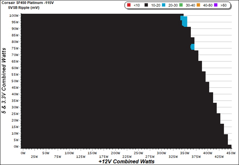
Ripple Charts
Infrared Images
We apply half-load for 10 minutes with the PSU’s top cover and cooling fan removed before taking photos with our modified FLIR E4 camera that delivers 320×240 IR resolution (76,800 pixels).
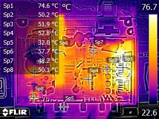
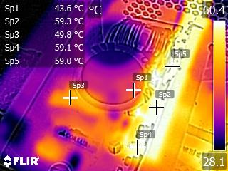
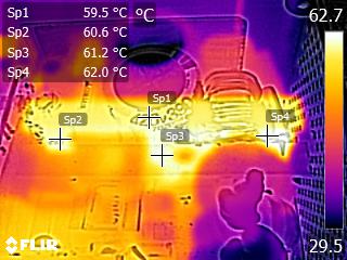
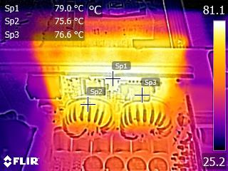
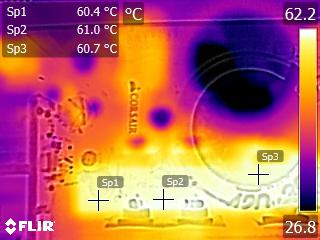
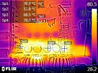
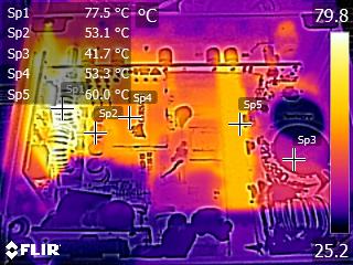
The temperatures on the VRMs are high and probably this is why the passive operation doesn't last long.
The caps near the VRMs get quite hot as well, however from the moment they are polymers and not electrolytics, this won't be a problem. Moreover, under real life conditions the load on the minor rails will be much lower than the one that we applied during those tests.
Advanced Transient Response Tests
For details on our transient response testing, please click here.
These tests are crucial because they simulate the transient loads a PSU is likely to handle (such as booting a RAID array or an instant 100 percent load of CPU/GPUs). We call these “Advanced Transient Response Tests” and they are designed to be very tough to master, especially for a PSU with a capacity of less than 500W.
In all of the tests, we use an oscilloscope to measure the voltage drops caused by the transient load. The voltages should remain within the ATX specification's regulation limits.
We should note that the ATX spec requires for capacitive loading during the transient rests, but in our methodology we chose to apply the worst case scenario with no extra capacitance on the rails.
Advanced Transient Response at 20 Percent – 200ms
| Voltage | Before | After | Change | Pass/Fail |
|---|---|---|---|---|
| 12V | 12.083V | 11.826V | 2.13% | Pass |
| 5V | 5.050V | 4.949V | 2.00% | Pass |
| 3.3V | 3.349V | 3.260V | 2.66% | Pass |
| 5VSB | 5.020V | 4.968V | 1.04% | Pass |
Advanced Transient Response at 20 Percent – 20ms
| Voltage | Before | After | Change | Pass/Fail |
|---|---|---|---|---|
| 12V | 12.073V | 11.756V | 2.63% | Pass |
| 5V | 5.049V | 4.930V | 2.36% | Pass |
| 3.3V | 3.348V | 3.245V | 3.08% | Pass |
| 5VSB | 5.021V | 4.962V | 1.18% | Pass |
Advanced Transient Response at 20 Percent – 1ms
| Voltage | Before | After | Change | Pass/Fail |
|---|---|---|---|---|
| 12V | 12.072V | 11.723V | 2.89% | Pass |
| 5V | 5.049V | 4.935V | 2.26% | Pass |
| 3.3V | 3.348V | 3.245V | 3.08% | Pass |
| 5VSB | 5.021V | 4.979V | 0.84% | Pass |
Advanced Transient Response at 50 Percent – 200ms
| Voltage | Before | After | Change | Pass/Fail |
|---|---|---|---|---|
| 12V | 12.067V | 11.816V | 2.08% | Pass |
| 5V | 5.047V | 4.940V | 2.12% | Pass |
| 3.3V | 3.345V | 3.251V | 2.81% | Pass |
| 5VSB | 5.005V | 4.947V | 1.16% | Pass |
Advanced Transient Response at 50 Percent – 20ms
| Voltage | Before | After | Change | Pass/Fail |
|---|---|---|---|---|
| 12V | 12.062V | 11.762V | 2.49% | Pass |
| 5V | 5.046V | 4.924V | 2.42% | Pass |
| 3.3V | 3.344V | 3.235V | 3.26% | Pass |
| 5VSB | 5.006V | 4.951V | 1.10% | Pass |
Advanced Transient Response at 50 Percent – 1ms
| Voltage | Before | After | Change | Pass/Fail |
|---|---|---|---|---|
| 12V | 12.062V | 11.771V | 2.41% | Pass |
| 5V | 5.046V | 4.918V | 2.54% | Pass |
| 3.3V | 3.344V | 3.241V | 3.08% | Pass |
| 5VSB | 5.006V | 4.955V | 1.02% | Pass |
![]()
![]()
![]()
![]()
![]()
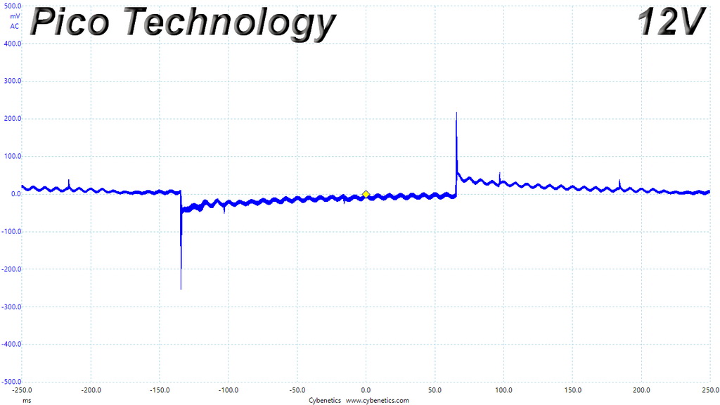
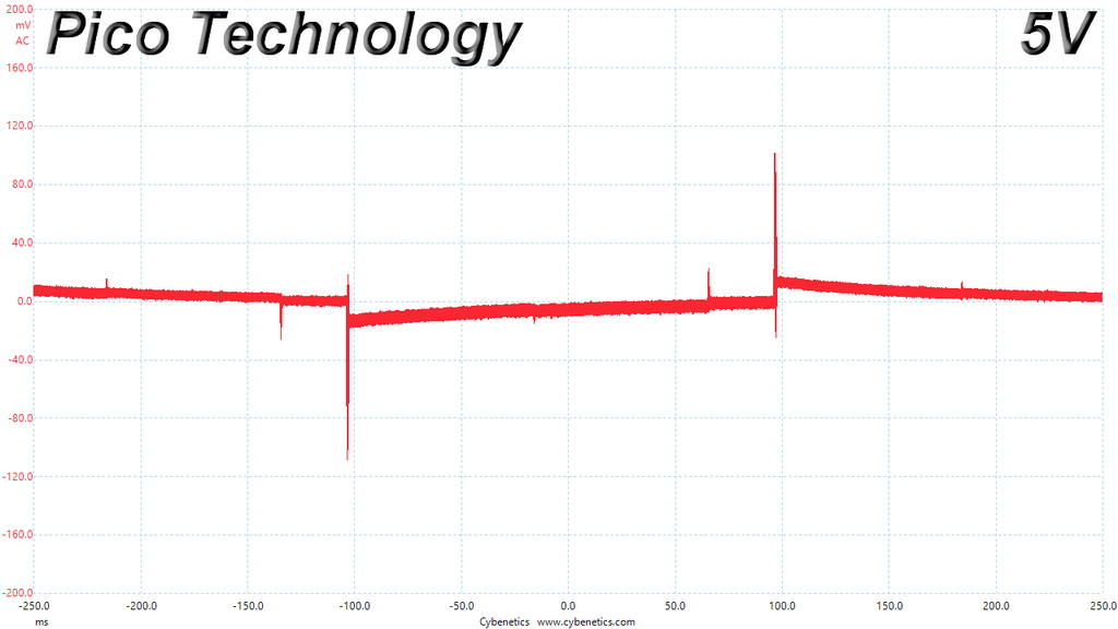
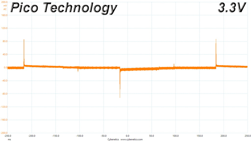
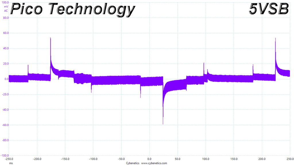
The transient response is very good on the minor rails but a little higher than expected at +12V. We would like to see a closer to 1% deviation on this rail, which is the most important of all.
Here are the oscilloscope screenshots we took during Advanced Transient Response Testing:
Transient Response At 20 Percent Load – 200ms
Transient Response At 20 Percent Load – 20ms
Transient Response At 20 Percent Load – 1ms

Transient Response At 50 Percent Load – 200ms
Transient Response At 50 Percent Load – 20ms
Transient Response At 50 Percent Load – 1ms
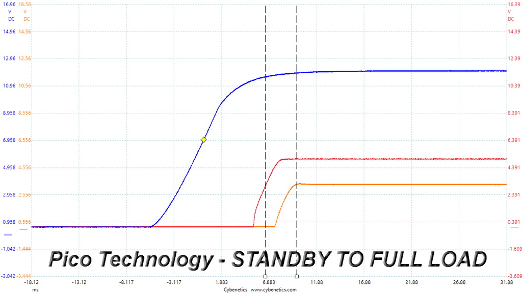
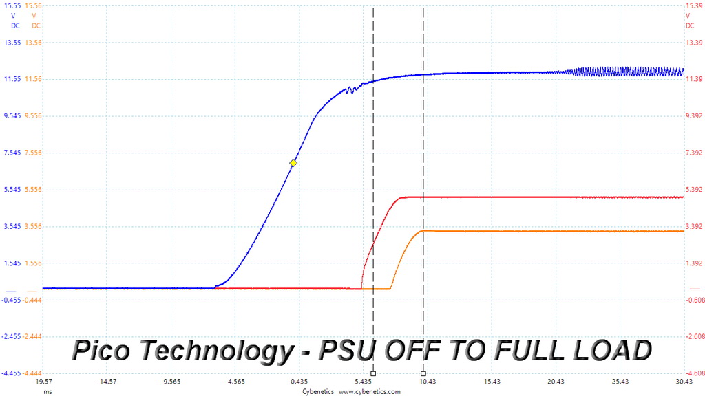
Turn-On Transient Tests
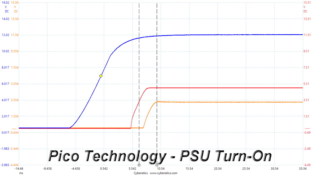
In the next set of tests, we measure the SF450’s response in simpler transient load scenarios—during its power-on phase.
For our first measurement, we turn the PSU off, dial in the maximum current the 5VSB rail can handle, and switch the PSU back on.
In the second test, we dial the maximum load the +12V rail can handle and start the PSU while it is in standby mode. In the last test, while the PSU is completely switched off (we cut off the power or switch the PSU off through its power switch), we dial the maximum load the +12V rail can handle before restoring power. The ATX specification states that recorded spikes on all rails should not exceed 10 percent of their nominal values (+10 percent for 12V is 13.2V, and 5.5V for 5V).
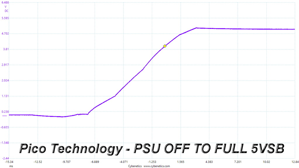
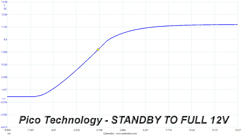
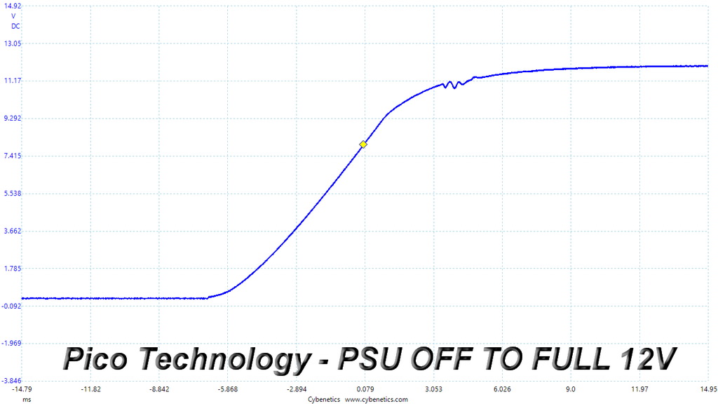
All slopes ramp-up smoothly and the rise time is within the allowed by the ATX spec range, which is 0.2-20ms.
To learn how we measure ripple, please click here.
The following table includes the ripple levels we measured on the SF450’s rails. The limits, according to the ATX specification, are 120mV (+12V) and 50mV (5V, 3.3V, and 5VSB).
| Test | 12V | 5V | 3.3V | 5VSB | Pass/Fail |
| 10% Load | 5.5 mV | 6.8 mV | 4.5 mV | 7.6 mV | Pass |
| 20% Load | 8.5 mV | 7.2 mV | 5.3 mV | 9.2 mV | Pass |
| 30% Load | 11.0 mV | 7.6 mV | 5.6 mV | 9.0 mV | Pass |
| 40% Load | 12.7 mV | 7.9 mV | 6.2 mV | 8.6 mV | Pass |
| 50% Load | 15.2 mV | 8.7 mV | 6.8 mV | 8.7 mV | Pass |
| 60% Load | 26.5 mV | 9.4 mV | 8.7 mV | 11.3 mV | Pass |
| 70% Load | 18.9 mV | 10.2 mV | 10.2 mV | 10.2 mV | Pass |
| 80% Load | 19.9 mV | 11.0 mV | 11.7 mV | 11.2 mV | Pass |
| 90% Load | 21.7 mV | 11.3 mV | 11.1 mV | 12.5 mV | Pass |
| 100% Load | 23.3 mV | 12.0 mV | 11.1 mV | 13.6 mV | Pass |
| 110% Load | 25.8 mV | 12.1 mV | 10.9 mV | 14.7 mV | Pass |
| Crossload 1 | 9.9 mV | 11.6 mV | 11.2 mV | 15.6 mV | Pass |
| Crossload 2 | 23.6 mV | 8.1 mV | 6.8 mV | 15.0 mV | Pass |
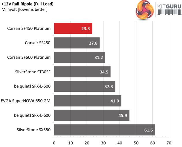
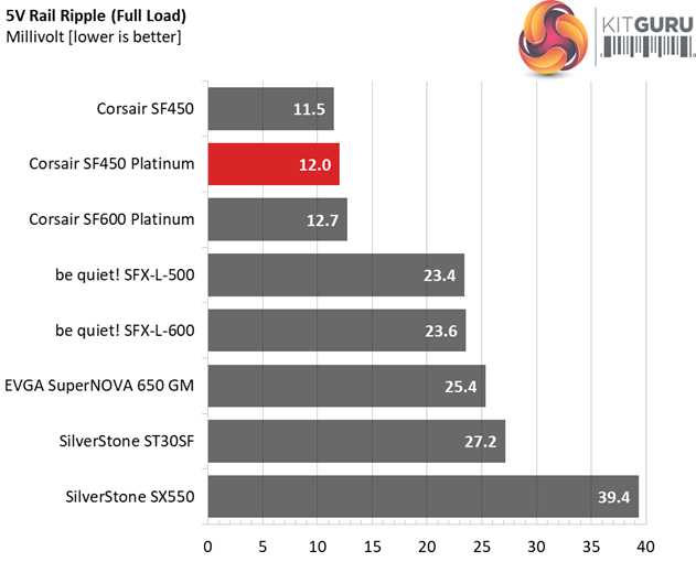
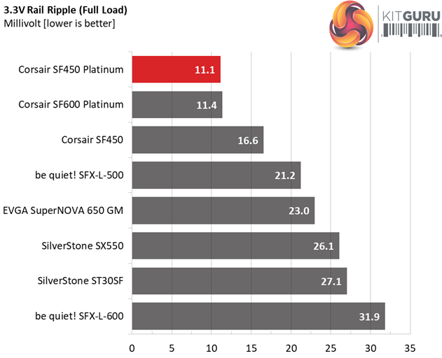
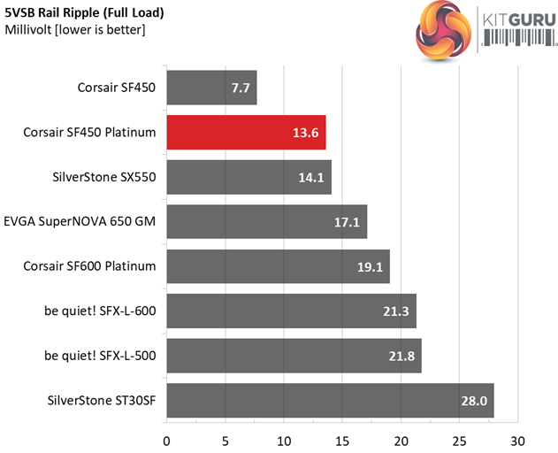
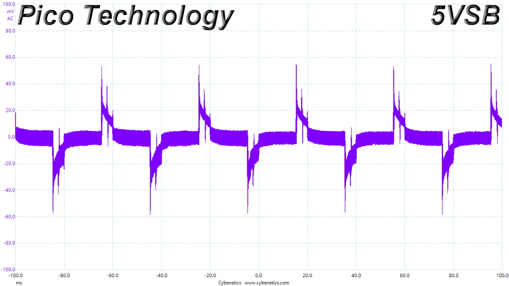
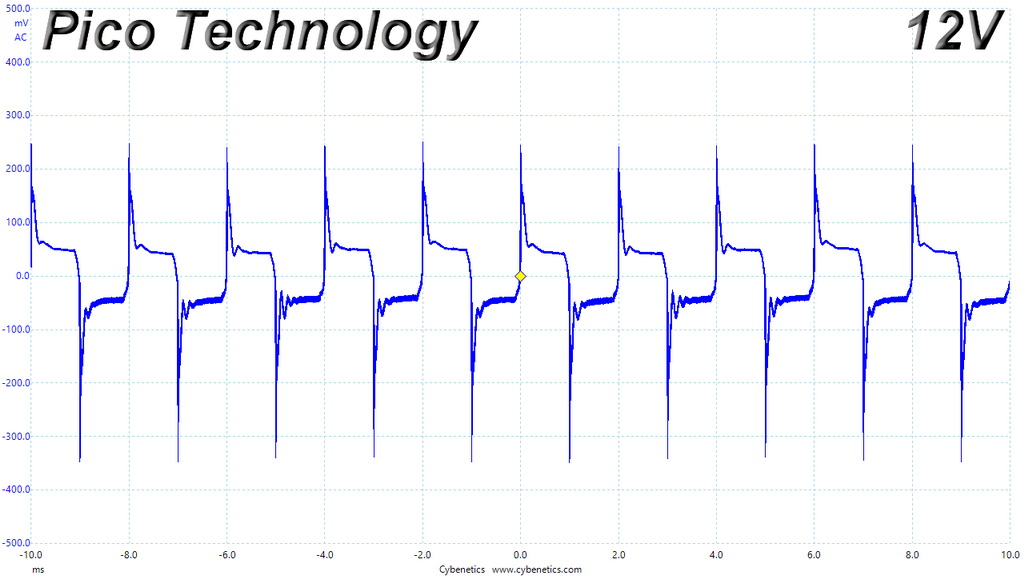
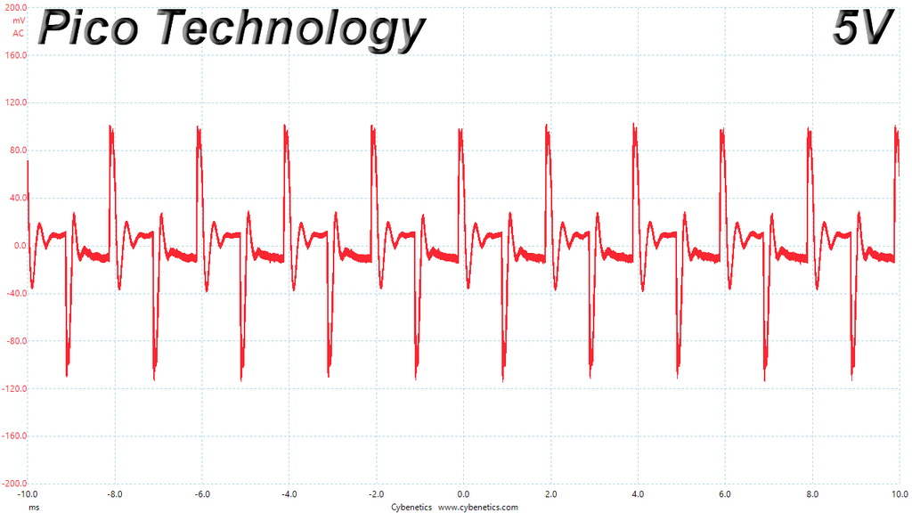
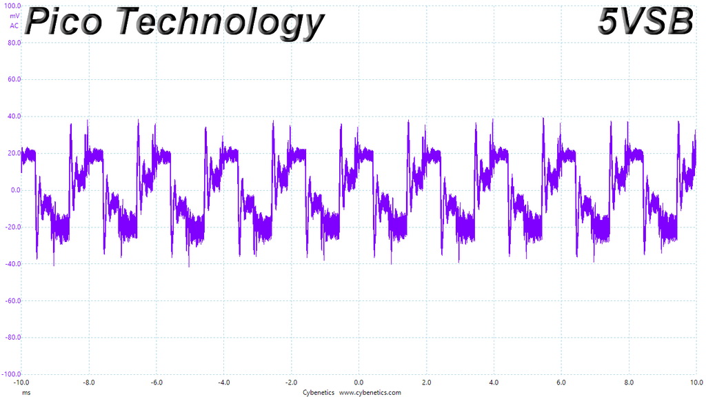
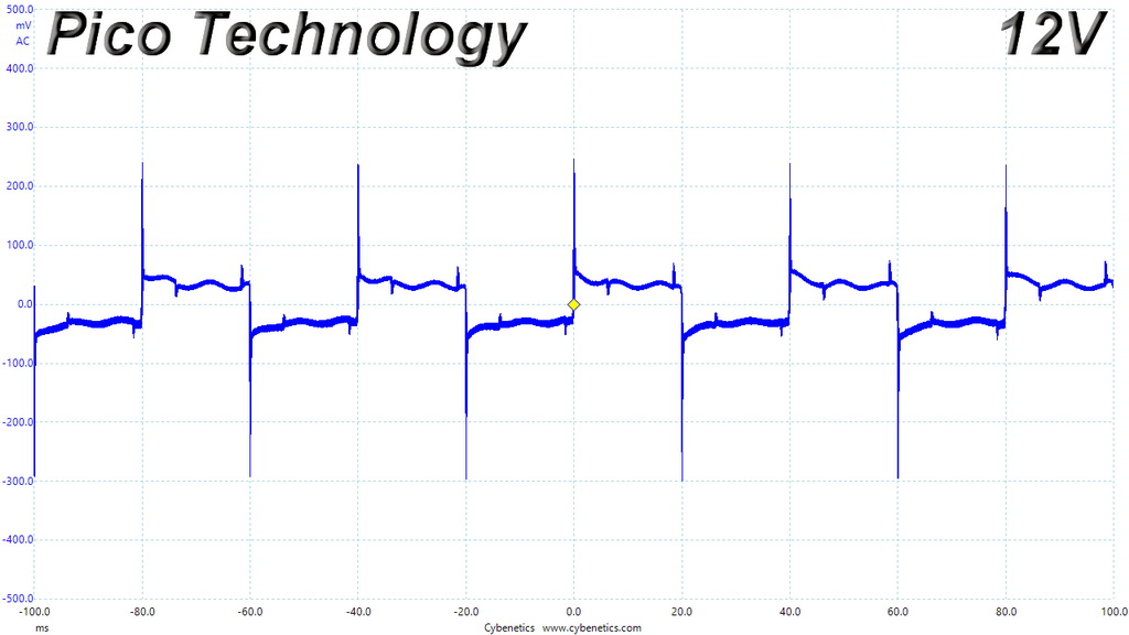
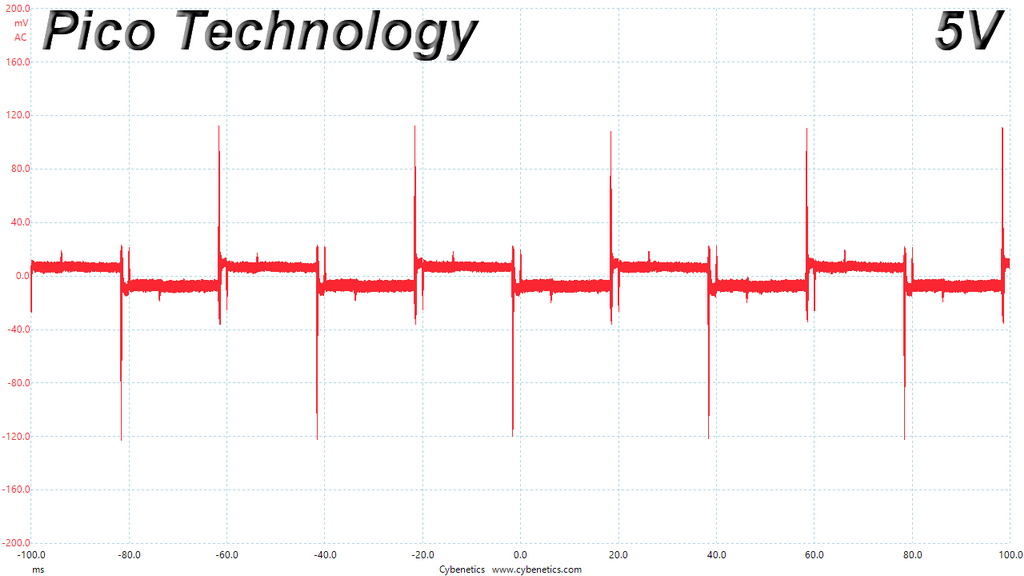
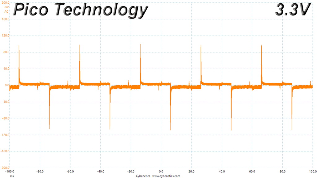
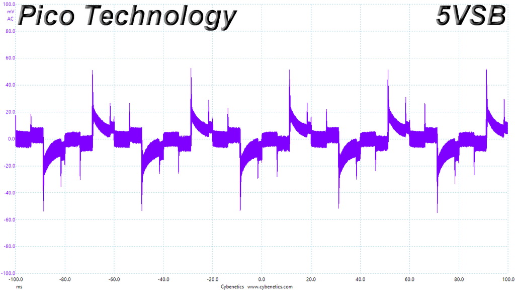
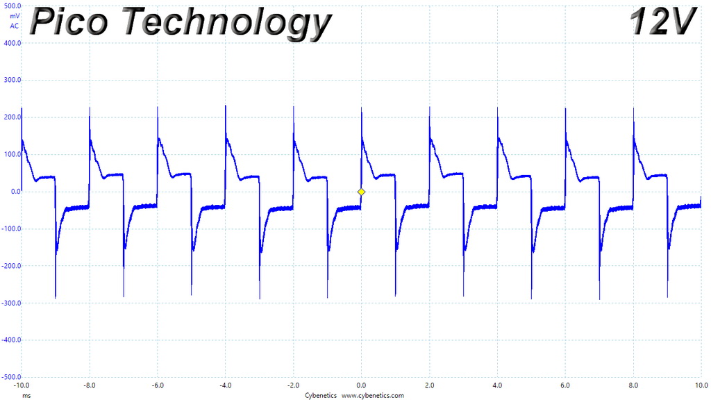
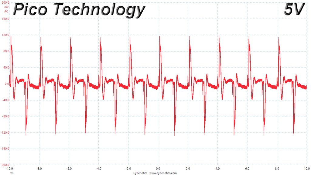
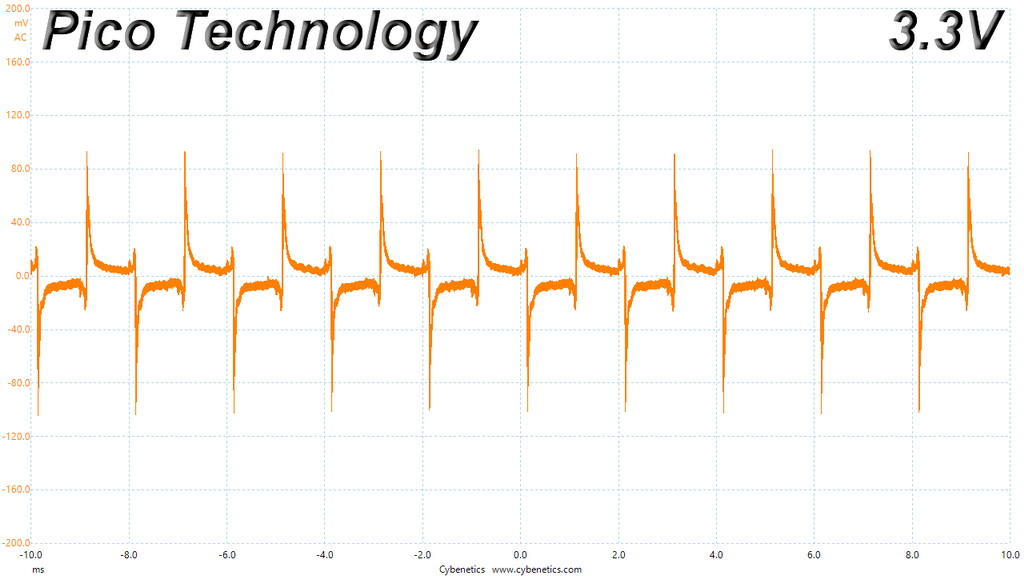
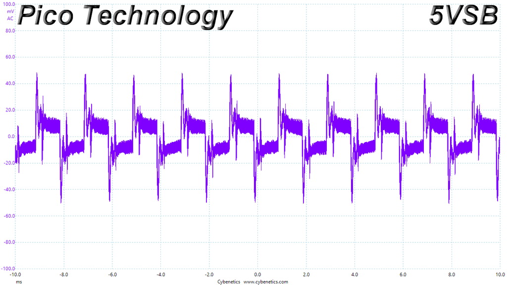
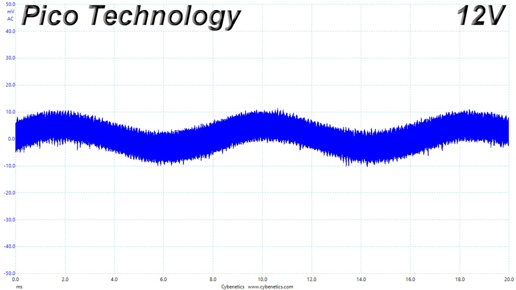
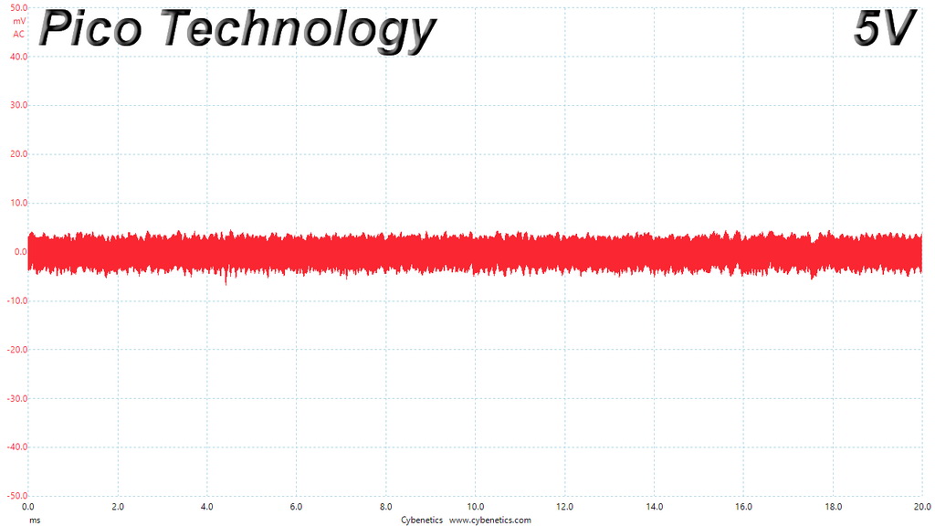
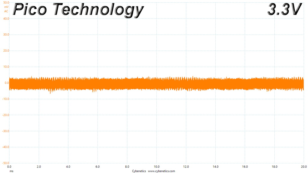
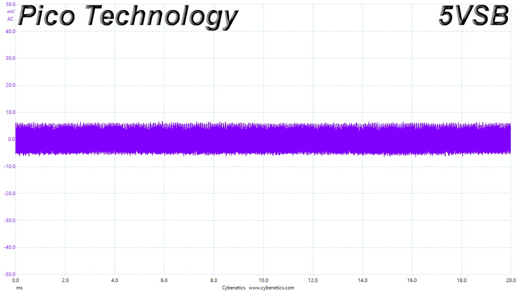
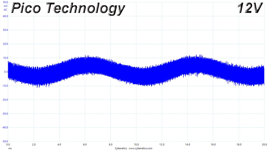
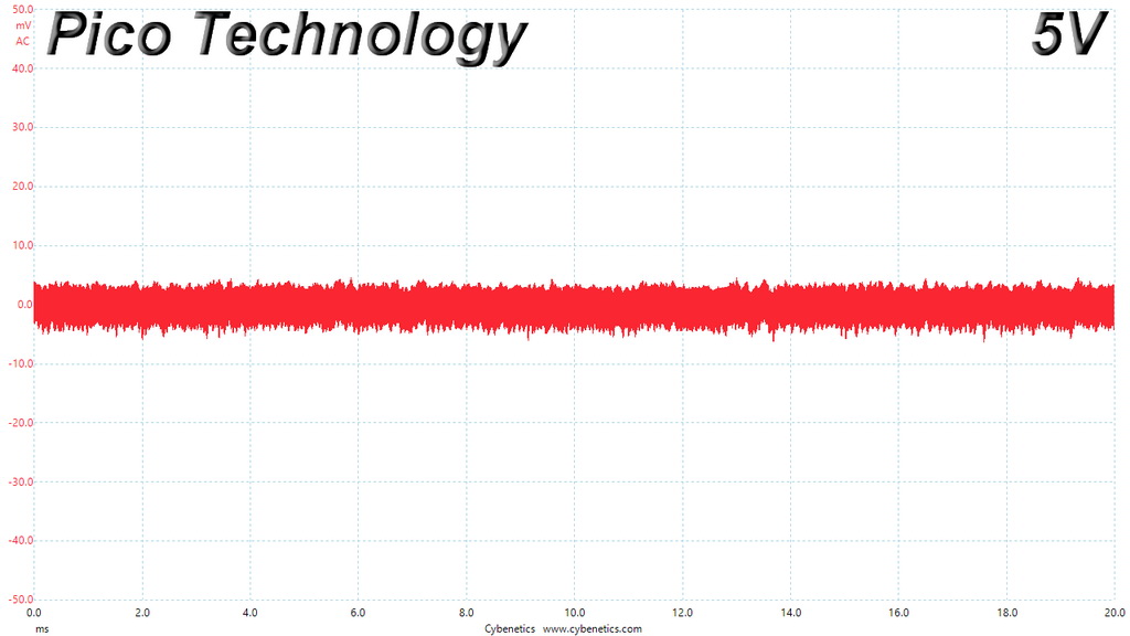
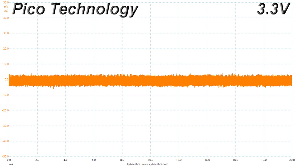
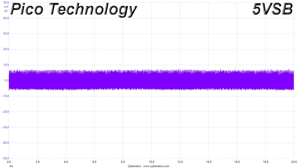
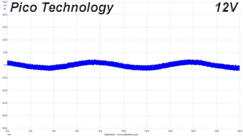
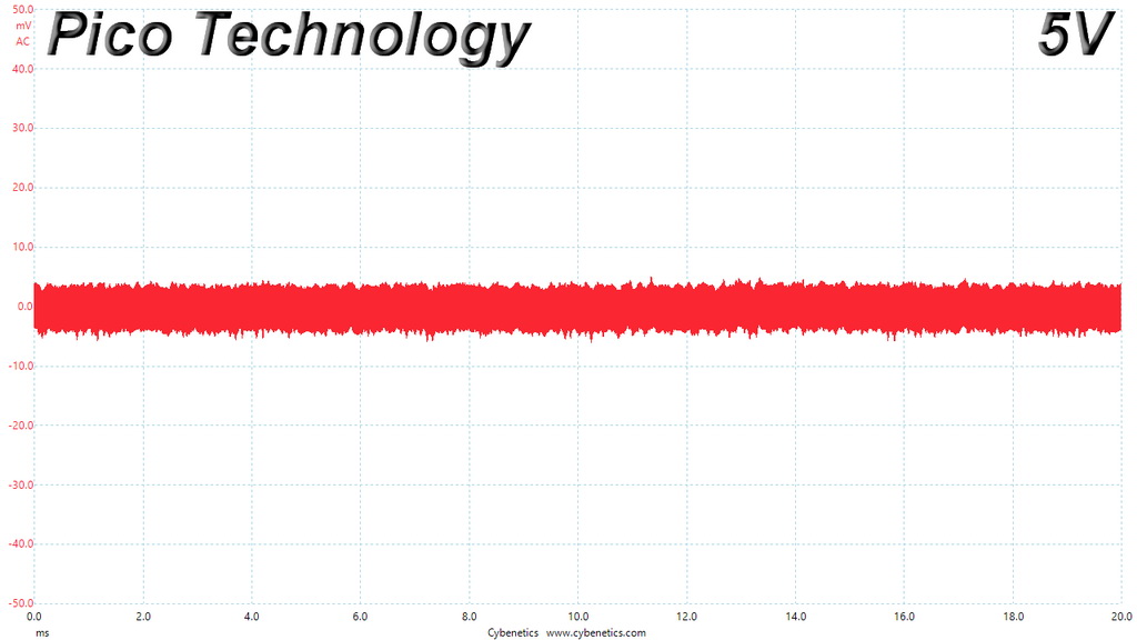
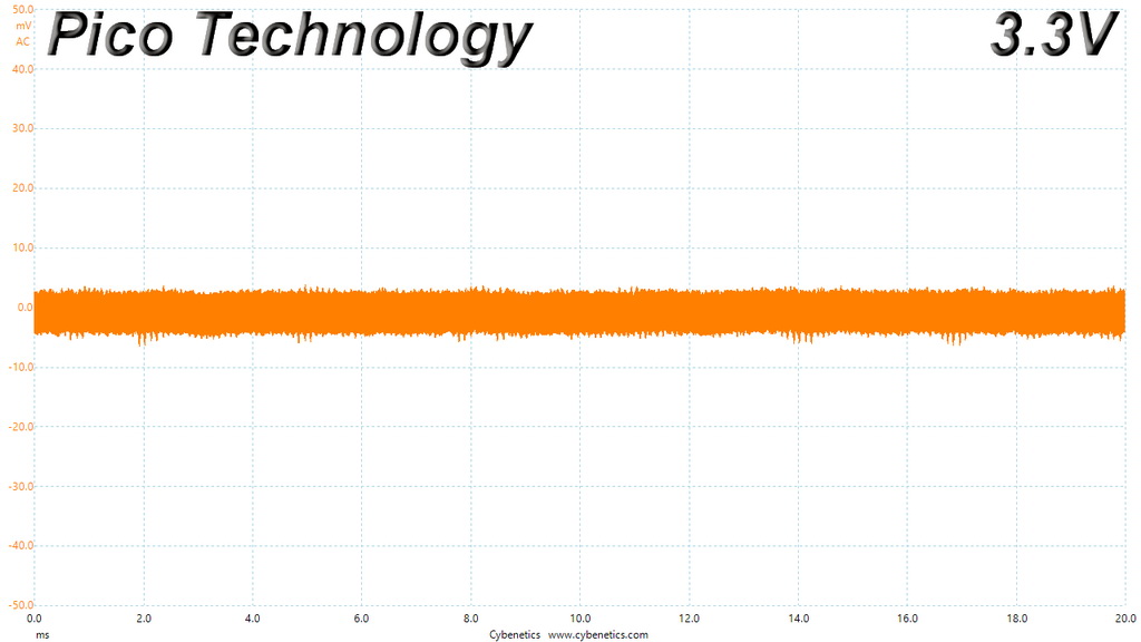
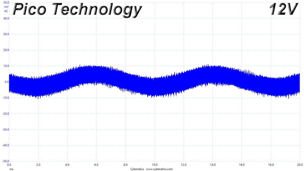
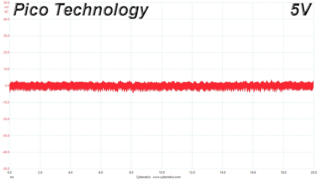
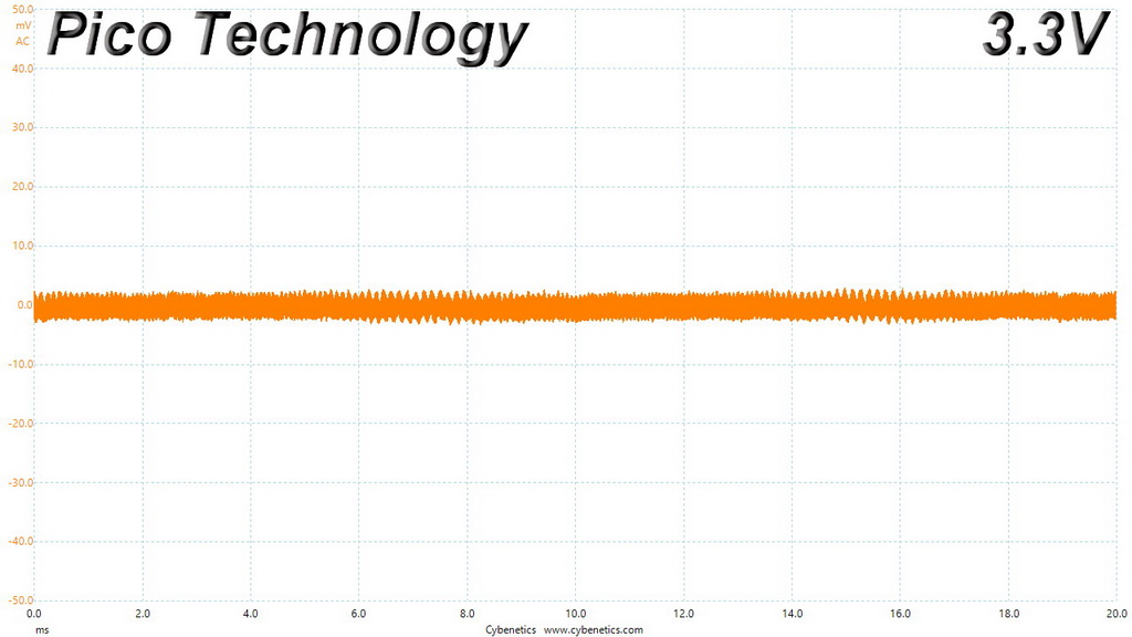
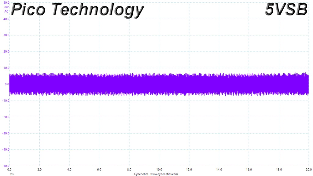
The ripple suppression is very good on all rails. You shouldn't expect to find the below 10mV readings that the high-end ATX units achieve, since the available space in the secondary side is limited in SFX units and Corsair didn't use in-cable caps. In any case though, 23.3mV of ripple at +12V under full load at 47°C is top-notch performance.
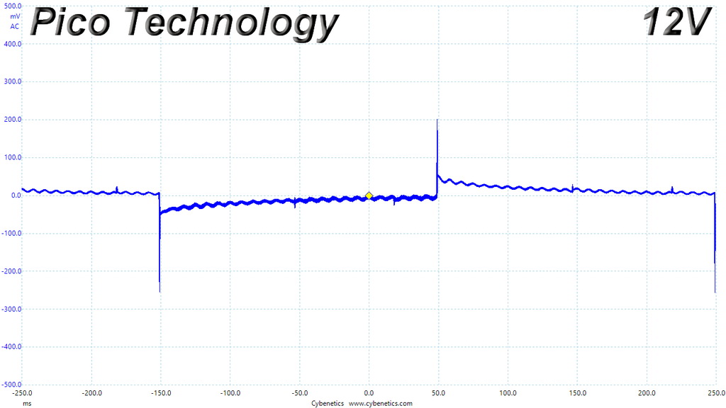
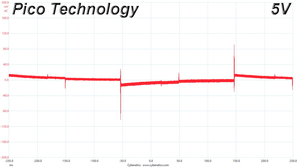
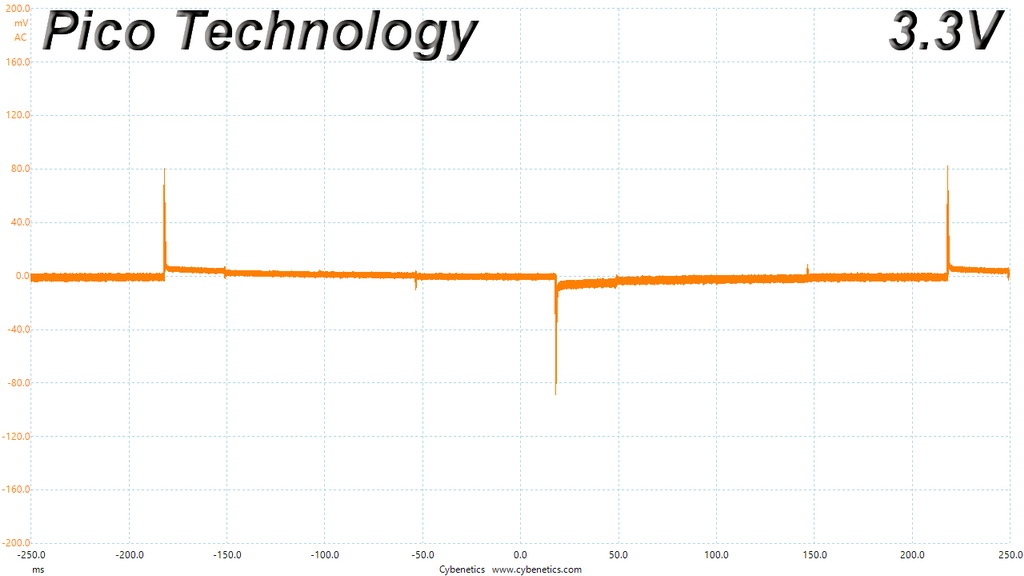
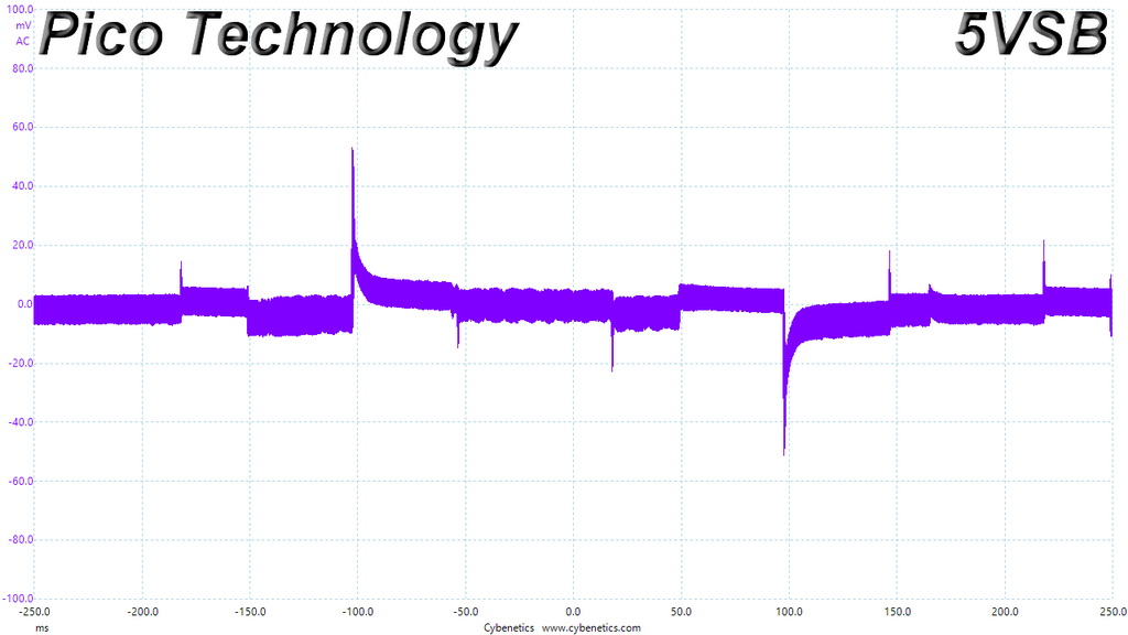
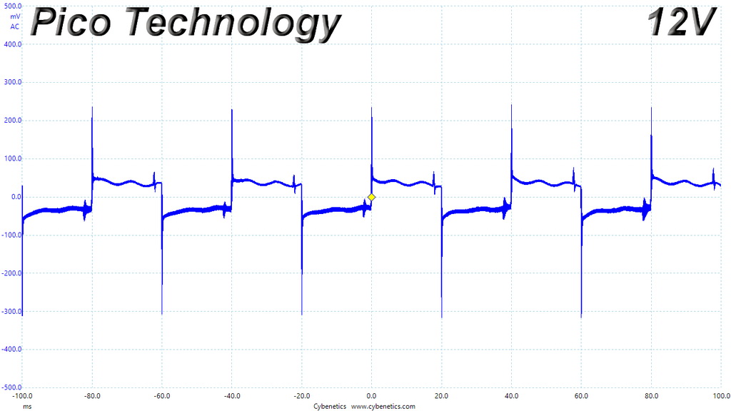
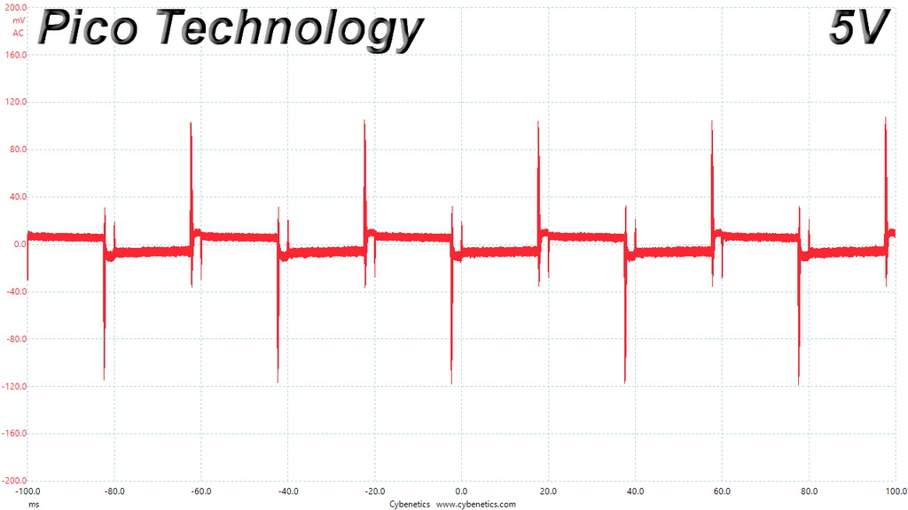
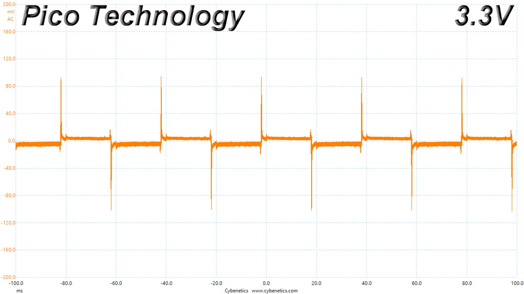
Ripple Oscilloscope Screenshots
The following oscilloscope screenshots illustrate the AC ripple and noise registered on the main rails (+12V, 5V, 3.3V and 5VSB). The bigger the fluctuations on the screen, the bigger the ripple/noise. We set 0.01 V/Div (each vertical division/box equals 0.01V) as the standard for all measurements.
Ripple At Full Load
Ripple At 110-Percent Load
Ripple At Cross-Load 1
Ripple At Cross-Load 2
Performance Rating
The following graph shows the unit’s total performance rating, comparing it to other units we have tested. To be more specific, the tested unit is shown as 100 percent, and every other unit's performance is shown relative to it.
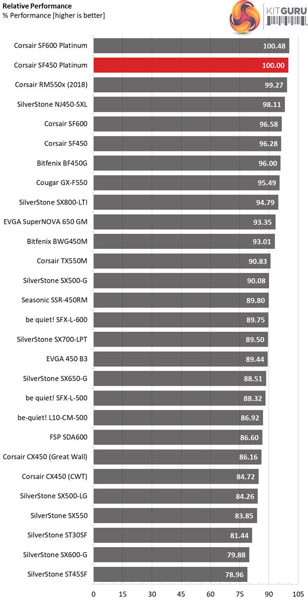
The SF450 and SF600 Platinum are the performance leaders in the small form factor category, with SilverStone's passive SFX-L model following closely.
Performance Per Dollar
The following chart may be the most interesting to many of you because it depicts the product’s performance-per-dollar score. We looked up the current price of each PSU on popular online shops and used those prices and all relative performance numbers to calculate the index. Note that all of the numbers in the following graphs are normalized by the rated power of each unit.
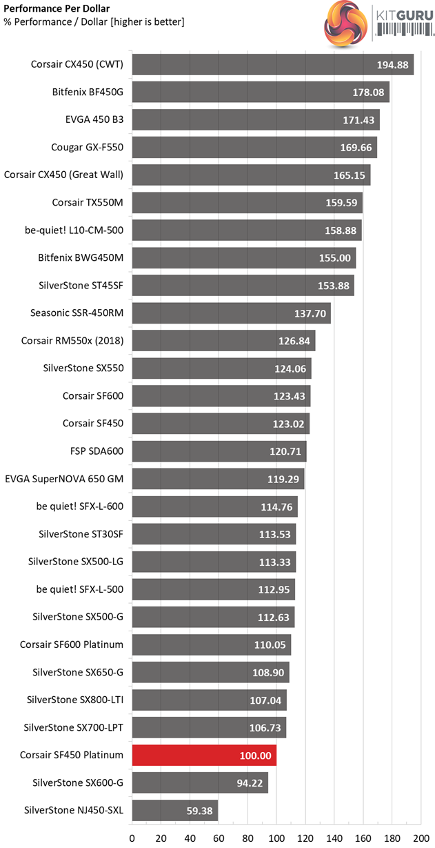
The Gold SF450 achieves a notably higher performance per buck score, thanks to its lower price tag. If you want top-notch efficiency though, then the Platinum model is definitely the one to get.
Noise Rating
The graph below depicts the cooling fan's average noise over the PSU's operating range, with an ambient temperature between 30°C and 32°C (86°F to 89.6°F).
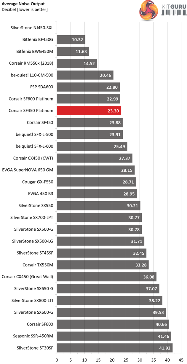
The difference in overall noise output is not so large between the Gold and Platinum SF450 models. On the contrary, the difference is enormous in the SF600 units.
Efficiency Rating
The following graph shows the PSU's average efficiency throughout its operating range, with an ambient temperature close to 30°C.
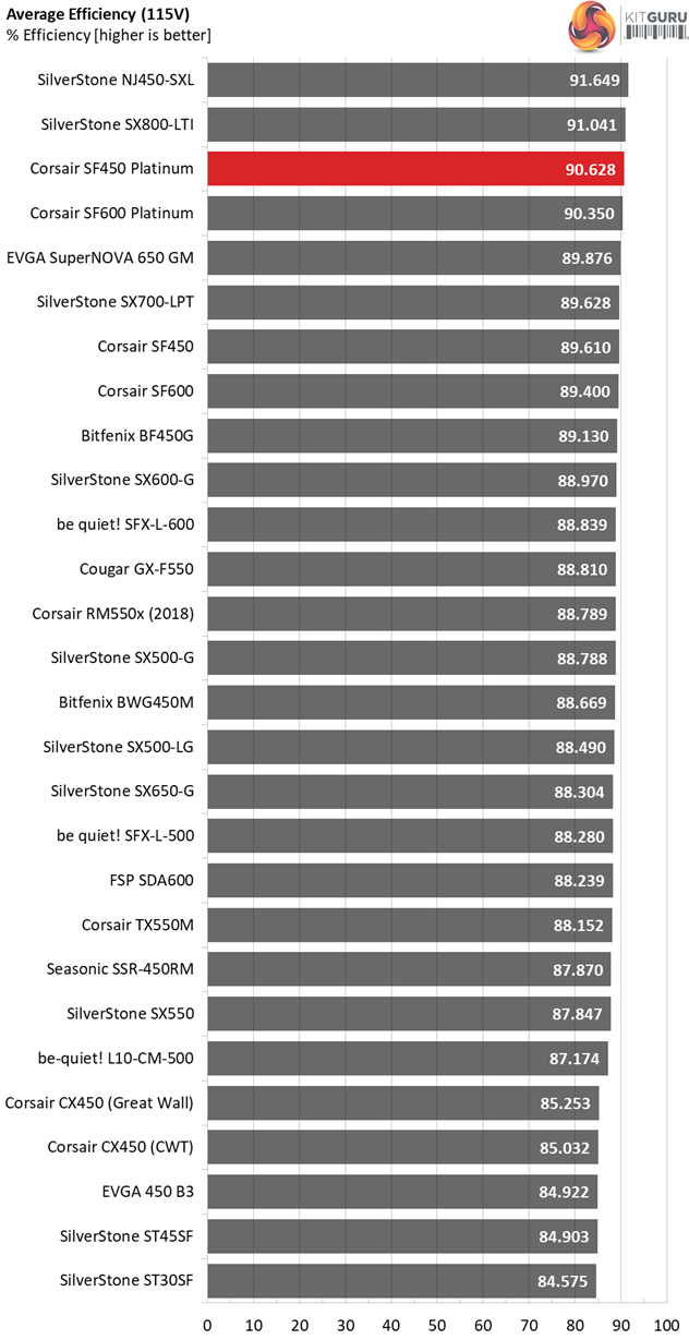
The SF450 Platinum is very close to the requirements of the Cybenetics ETA-A+ standard (>91% overall efficiency), which even a number of 80 PLUS Titanium units fail to meet. With a little more tuning this platform could meet the Titanium requirements, but it would probably had to sacrifice performance in other areas.
The Corsair SF450 Platinum retails for $115 in the US while in the UK market it is on sale for £106.99.
Corsair holds dominance in the SFX market with the addition of these new SF Platinum models. I have been impressed with the performance of the SF600 Platinum unit and the market position is cemented with this SF450. The cooperation between Corsair and Great Wall has brought some great results so far. We are looking forward to getting our hands on the Corsair SF750 – just to see what the more powerful unit can deliver.
The Corsair SF450 Platinum is obviously priced higher than its Gold rated counterpart. The major differences between these two models are the higher efficiency of the Platinum model and the much more efficient 5VSB rail.
The overall performance difference is about 3.7% in favour of the SF450 Platinum, while the overall noise output is about the same for both platforms, which isn't a bad thing as both units are extremely quiet under real world conditions. If you are not interested in the 1% efficiency increase and the 3.7% performance difference – and you don't need the SFX-to-ATX adapter (only bundled with the Platinum SF models), you can opt for the SF450 Gold which achieves a higher performance per buck score.
The small form factor power supply categories are hotly contested lately with more and more brands releasing compatible offerings. This downsizing trend is also popular in the ATX category, where we can find many mid-capacity units at only 140mm depth.
With the provided SFX-to-ATX adapter the SF450 Platinum can also used with normal chassis, however the short cables will force some limits. It would be nice if Corsair offered all of its SF models with two different cable configurations (short and long) in order to cover all possible scenarios. The corresponding adapter is already provided with the new SF Platinum models, so it is natural for users to ask for a set of longer cables as well.
![]()
You can get the SF450 Platinum from Overclockers UK for £106.99 inc VAT HERE.
Pros:
- Delivered full power at 47°C.
- Highly efficient.
- Top efficiency at 5VSB.
- Great overall performance.
- Silent operation.
- Excellent build quality.
- Fully modular.
- Individually sleeved cables.
- SFX-to-ATX bracket included in the bundle.
- 7-year warranty.
Cons:
- The transient response at +12V could be better.
- The semi-passive mode cannot be deactivated.
- Turn-off overshoot at +12V should be lower.
- High inrush current with 230V input.
KitGuru says: The SF450 Platinum is the best SFX 450W PSU that money can buy today. It offers a significant performance and efficiency increase over the SF450 Gold and it is also bundled with individually-sleeved cables and an SFX-to-ATX adapter, allowing you to install the PSU in a ATX chassis. Corsair seals its domination in the SFX category with the new SF Platinum models.