

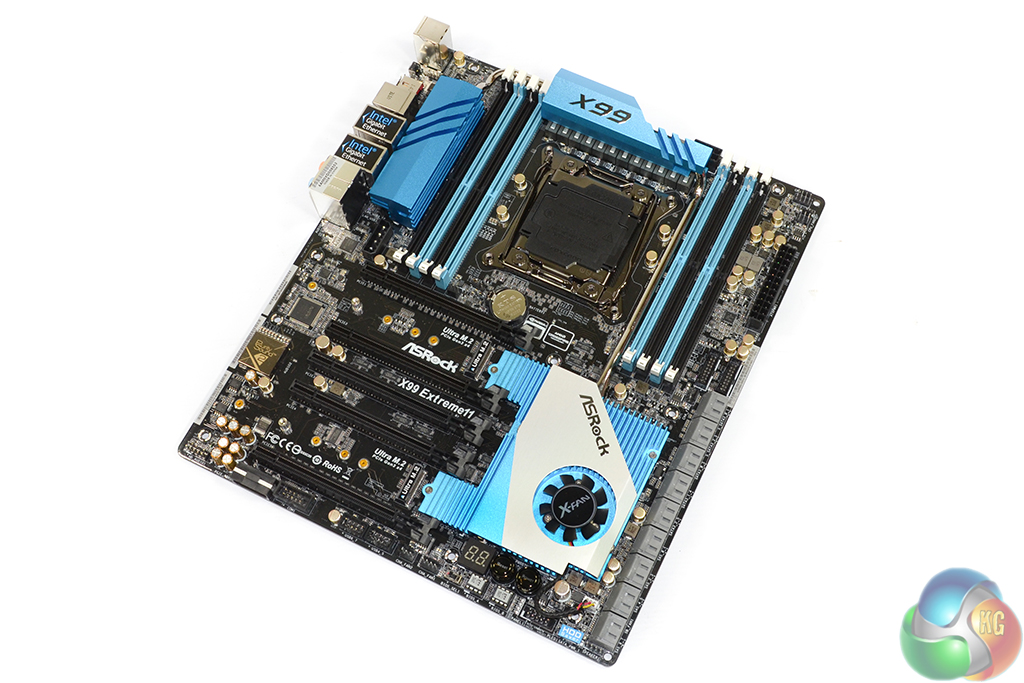
Given a potential target audience of high-performance enthusiasts (who may value aesthetics), ASRock maintains its recently-adopted light blue and black colour scheme for the X99 Extreme11.
The motherboard is widened to the E-ATX form factor in order to provide area for the sizable array of components.
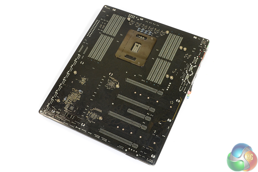
ASRock does a good job of keeping the PCB's all-black appearance, even under bright light. A look at the motherboard's rear side reveals the physical PCIe lane allocations and also shows a 1Mb MRAM chip from Everspin.
Marked as an MR0D08BMA45, the magnetoresistive random access memory chip is used to provide rapid access to permanently stored, critical data. It is intended to function with the LSI storage controller.
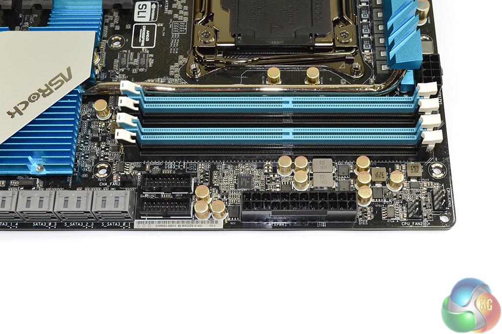
We took an in-depth look at ASRock's twelve-phase CPU power delivery system in our review of the company's X99 OC Formula motherboard, over here. The system deployed for the X99 Extreme11 is similar in many respects.
In short, the system uses 60A chokes, twelve MOSFETs, and 12,000 hour-rated (although significantly longer at realistic usage temperatures) Nichicon ‘Platinum' capacitors to provide power. Electronic management is conducted by Intersil's ISL6379 PWM controllers and six rear-mounted ISL6611A phase doublers from the same vendor.
All-in, the X99 Extreme11's power delivery system is not as pumped-up as that used on the X99 OC Formula, but it still looks to be capable of handling heavy overclocks, nevertheless.
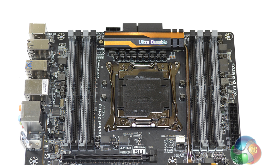
The eight DDR4 memory slots provide support for up to 128GB of quad-channel memory with operating frequencies in excess of 3200MHz (depending on other hardware's capabilities). Both ECC and non-ECC memory is supported, the former of which requires a Xeon processor for operation.
Two outwards-facing USB 3.0 headers provide a total of four SuperSpeed ports for front panel usage. To provide maximum bandwidth, ASRock does not use the popular ASM1074 bandwidth-dividing hub controller, instead opting to run each USB 3.0 connection directly from the X99 chipset.
Positioning of the headers keeps them away from potential interference. The decision not to go with a right-angled orientation is smart, given the board's already-wide E-ATX dimensions.
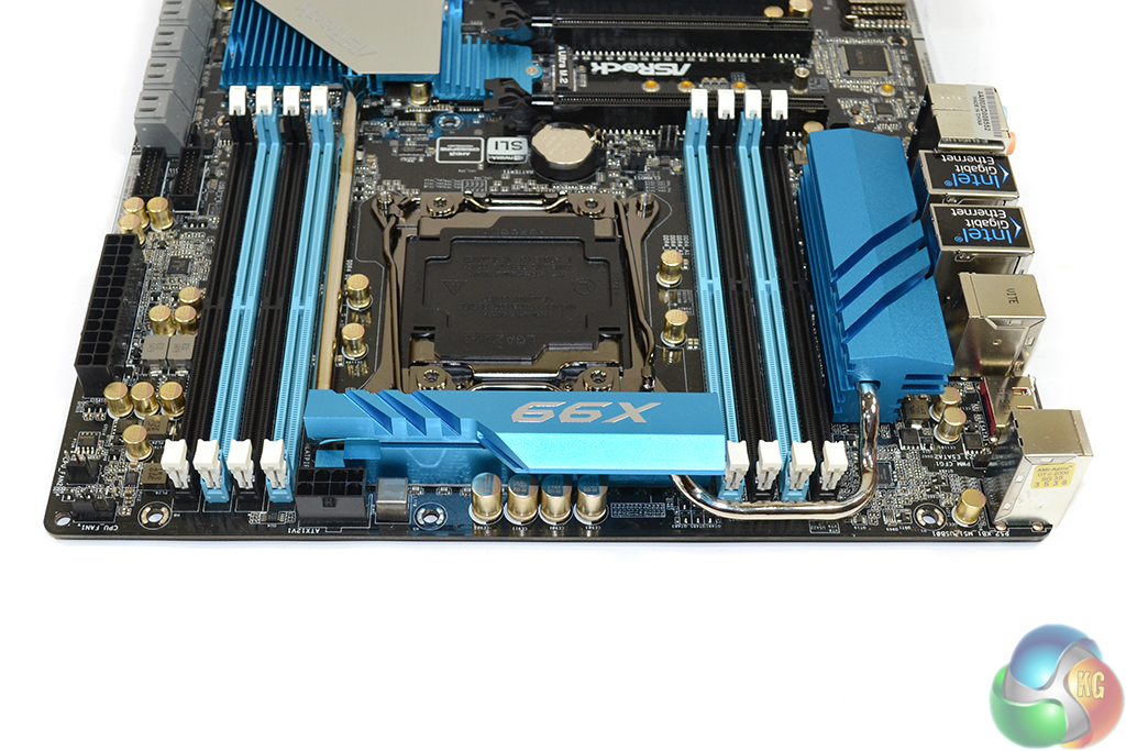
A few power delivery components and the 8-pin CPU power connector are nestled along the motherboard's top edge. The 8-pin EPS connector is further towards the 24-pin connector than usual, and its positioning may cause cable management issues.
ASRock's block diagram for the X99 Extreme11 is, by far, one of the most complex versions that I have seen. So let me try to make this explanation as clear as possible.
The PLX PEX8747 PCIe switch can take one 16-lane PCIe 3.0 input (from the CPU) and output up to 32 downstream lanes (in the form of expansion slots/components). For example, a 16-lane input can be split into x16/x16 or x16/x8/x8 or x8/x8/x8/x8 outputs.
Alternatively, ASRock feeds an x8 lane into the switch, with two x16 lanes being output (this approach decreases the upstream bandwidth to a Haswell-E CPU).
40-lane CPU operation:
4-card SLI and CrossFire are supported with 16 PCIe 3.0 lanes to every GPU, thanks to the pair of PEX8747 PCIe switches.
Assuming the LSI SAS 3008 storage controller is not being used, the first, second, fourth, and fifth PCIe slots are each fed with 16 lanes downstream of the PLX switches (one x16 lane input from the CPU to each PLX switch). That leaves eight CPU-fed PCIe 3.0 lanes to cater for the dual Ultra M.2 connectors. So 4-way SLI/CrossFire plus dual PCIe 3.0 x4 M.2 operation is possible.
And workstation users will be keen to know that PCIe slots three and four share sixteen PCIe 3.0 lanes between them. So two workstation graphics cards can be installed into those slots to receive eight PCIe 3.0 lanes each. In this case, the three other full-length PCIe slots will continue to operate at x16 bandwidth.
Adding the eight-lane LSI controller into the equation changes things a little. Eight PCIe 3.0 lanes are taken away from the first PEX8747 switch, which halves its communication bandwidth to the CPU. Two 16-lane PCIe outputs (slots one and two) are still supported, however.
28-lane CPU operation:
4-way, x16 SLI and CrossFire are still supported with the 28-lane 5820K CPU. That could result in a sizable cash saving for users who require PCIe connectivity without computer horsepower.
Up to sixteen lanes still feed into the first PEX8747 switch. As with the 40-lane solution, that number drops to eight if the LSI controller is using its eight lanes. Irrelevant of whether eight or sixteen lanes are being fed into the first PLX switch, two PCIe x16 outputs are provided.
The second PEX8747 switch is fed with a maximum of eight PCIe 3.0 lanes from the CPU. This allows up to two PCIe x16 outputs for graphics cards and the likes, and sharing of one of those x16 links is still possible between PCIe slots three and four.
That leaves us with a spare four PCIe 3.0 lanes from the 5820K's on-chip generator. ASRock diverts all four of those lanes to its upper Ultra M.2 connector, providing a single 32Gbps storage connection. The lower M.2 slot is left inactive for PCIe operation, although it can still support a SATA-based drive.
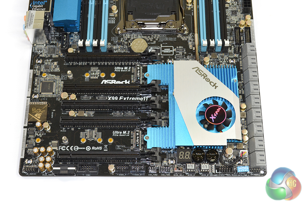
The standard affair of USB 2.0, front panel, and audio connectors are found along the X99 Extreme11 motherboard's bottom edge. ASRock also adds one of two 4-pin molex power connectors in this location to provide additional juice for heavy expansion configurations.
Dual BIOS chips, and a selector switch, for redundancy are positioned slightly below on-board power and reset buttons as well as a two-digit debug LED. The HDD Saver port is located towards the board's bottom-right corner.
Other than the on-board buttons and Dr. Debug display, there is nothing of considerable size on the bottom edge that will get blocked by an overhanging graphics card.
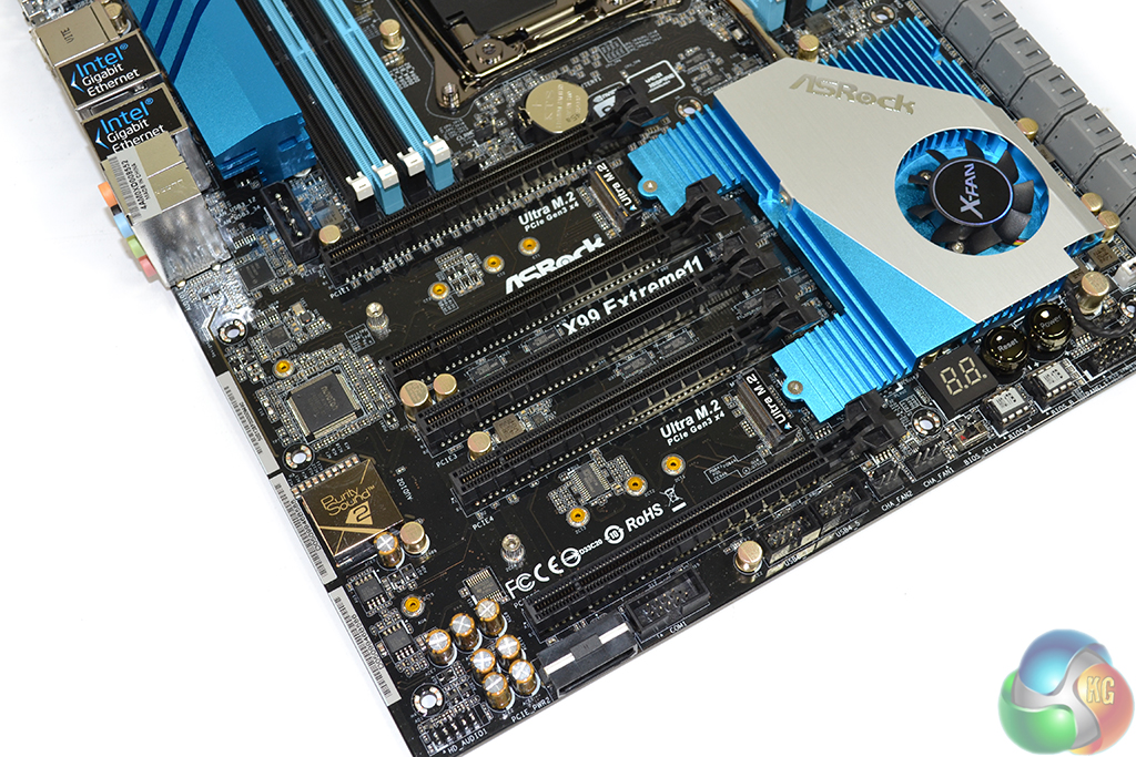
Given its storage-heavy design, it only makes sense that ASRock equips the X99 Extreme11 with two of the company's excellent Ultra M.2 connectors. We were impressed by Ultra M.2‘s performance when we tested it with the speedy Samsung XP941 SSD in our ASRock Z97 Extreme6 review.
The slots can use a PCIe 3.0 x4 connection directly from the CPU to provide up to 32Gbps of bandwidth each. They also support M.2 SATA connections by borrowing lanes from two of the chipset's SATA 6Gbps ports.
There is also the potential to software RAID a pair of PCIe-fed M.2 SSDs together to provide particularly high transfer rates.
All of the common M.2 form factors are supported, including the common 80mm-long design.
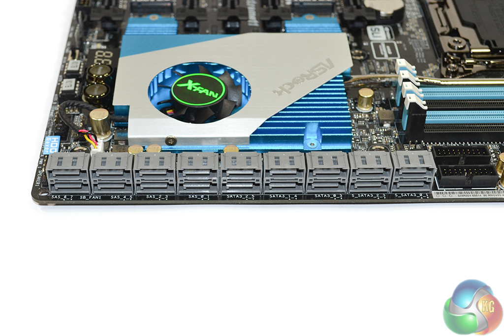
The ten SATA 6Gbps ports furthest to the right side are provided by the X99 chipset. Six of the ports support RAID, with the other four being useful for non-RAID purposes and sharing their connection with M.2 or eSATA connections.
With its eight-lane PCIe 3.0 connection directly to the CPU, the LSI SAS 3008 controller's eight SAS 12Gbps/SATA 6Gbps ports could be an important component for users with IO-heavy workloads. ASRock's promotional material shows the controller delivering transfer speeds of 6.1GBps.
RAID 0, 1, 1E, and 10 are supported by the LSI controller. I am surprised to see that RAID 5/6 support is omitted as I would think the combination of speed, redundancy, and drive cost would make it popular for IO-intensive workloads that deal with important data. That said, many users may deem RAID 1E a worthwhile substitute, albeit different in function.
There is no SATA Express on the X99 Extreme11, but given the sheer number and speed of alternative options (and the early popularity of M.2), I would not call this a negative point.
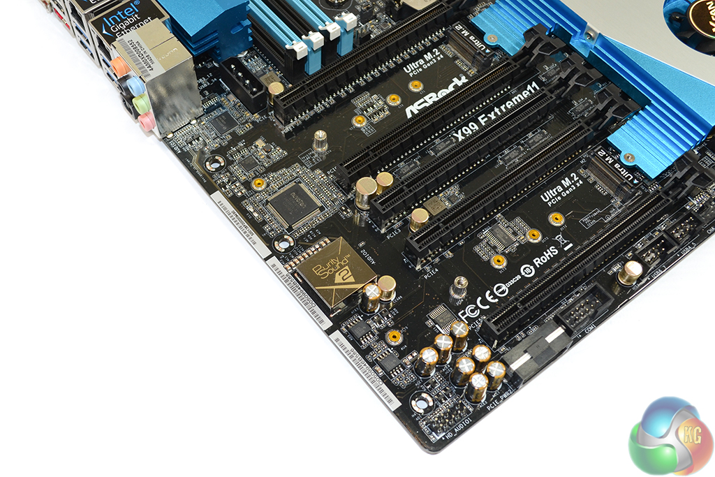
Realtek’s ALC1150 codec, with its 115dB signal-to-noise ratio (SNR), provides the foundation for ASRock’s Purity Sound 2 audio system. EMI shielding and a distinct PCB pathway are used to minimise signal interference.
A pair of Texas Instruments NE5532 operational-amplifiers are used to provide support for 600 Ohm headsets, while Nichicon fine gold series capacitors filter the audio signals.
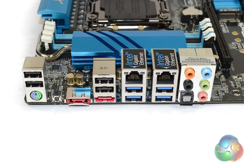
A total of four USB 2.0 ports and a single PS/2 connection provide peripheral installation points. Some people still use PS/2 keyboards, and old-school USB 2.0 is far more convenient than USB 3.0 when installing Windows 7, thanks to its inherent driver support.
Two eSATA connectors, in addition to four USB 3.0 ports (two of which operate from an ASMedia ASM1042AE PCIe 2.0 x2 host controller), continue the motherboard's storage theme. Intel I218-V and I211-AT Gigabit Ethernet NICs are used and can be teamed together.
Rear audio is fed by the Purity Sound 2 system, and a clear CMOS button provides convenience for overclockers using a chassis.
Thunderbolt 2 may have been a worthwhile addition to such a storage-centric board. Finding 20Gbps of bandwidth from the heavily-utilised X99 chipset would have required compromise elsewhere, but a PCIe 2.0-based PLX switch (such as the PEX8605) for lower bandwidth devices would have solved that issue. If you're going nuts on storage, why not offer everything that an enthusiast could ask for?
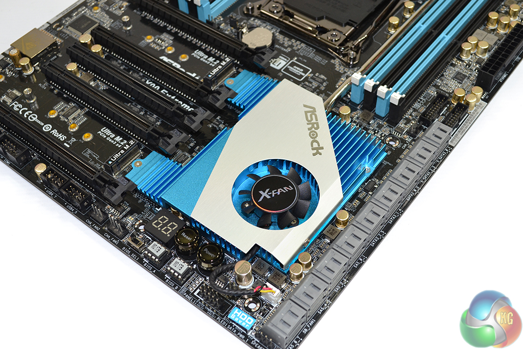
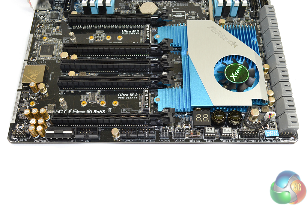
Covering the pair of PLX PEX8747 switches (which can drink up to 8W of power each) and the LSI SAS 3008 storage controller, not to mention the X99 PCH, ASRock is forced into using a sizeable, actively-cooled chipset heatsink.
The 37mm fan operates through its own header and can be speed-controlled via the UEFI or software. This is one of the louder chipset fans that I have worked with. It was clearly audible, even when idling, if the Corsair H100i fans were operating at reduced levels.
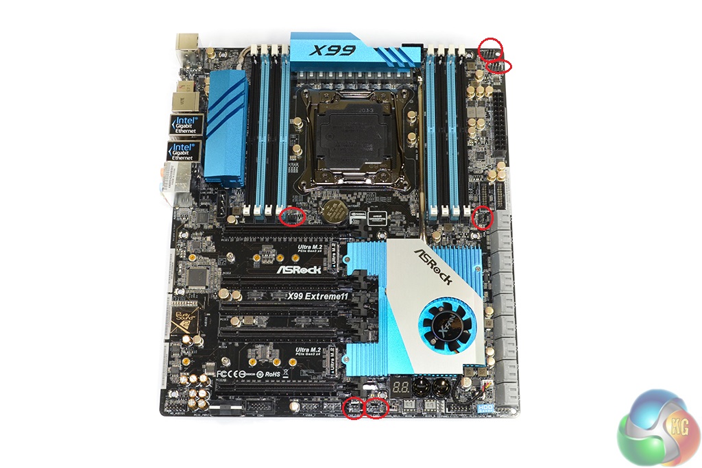
A total of six fan headers are found on the X99 Extreme11. Two headers (one 4-pin and the other 3-pin) in the top-right corner are allocated with the CPU fan duties. Their far-right positioning makes hiding CPU fan cables a little more difficult.
Sat just beneath the left-hand DIMM bank is a powered 3-pin fan header. While this is great for connecting the pump unit of an AIO liquid cooler, it is not good for connecting a rear chassis fan due to its lack of speed control.
The remaining three headers (one 4-pin along the bottom edge and two 3-pin) are all speed-controlled. Their distribution is optimised for connecting side panel and front chassis fans.

Hello Kitguru.Do you know which cases have at least 18 3.5″ drive bases to pair with this motherboard ?
Search for Lian LI bro