

The new be quiet! Pure Power 11 700W features a higher efficiency rating (80 PLUS Gold) than its predecessor and according to be quiet! it also delivers exceptionally quiet operation. Are those two enough though to justify the increased price tag?
Every year be quiet! releases a new Pure Power line, hitting the eleventh version this year. The Pure Power 11 series consists of both semi-modular and non-modular models, with the latter covering a large wattage range (300W to 700W) through six units. There are four semi modular supplies in the range and their capacities range from 400W to 700W. The major differences with the previous generation models are the increased efficiency levels (80 PLUS Gold Gold for the 400W and higher capacity units, instead of Silver) and the longer warranty (five vs three years).
In today's review we will evaluate the flagship model (model number L11-CM-700). It is based on a platform provided by FSP, which uses an Active Clamp Reset Forward (ACRF) topology in the primary side. This topology manages to offer high efficiency and a long hold-up, while using less (and lower cost) components compared to half/full bridge configurations. FSP is one of the very few brands that still utilize this topology – which doesn't tend to perform so well under transient loads.
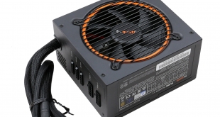
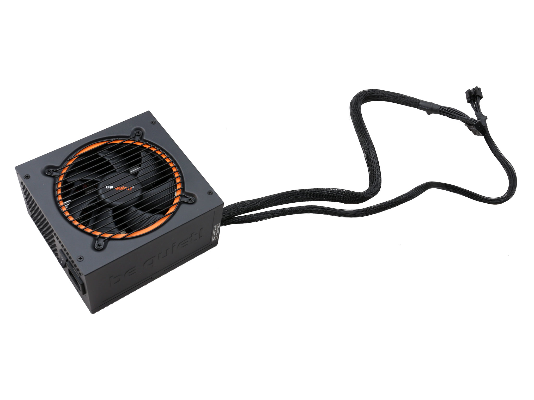
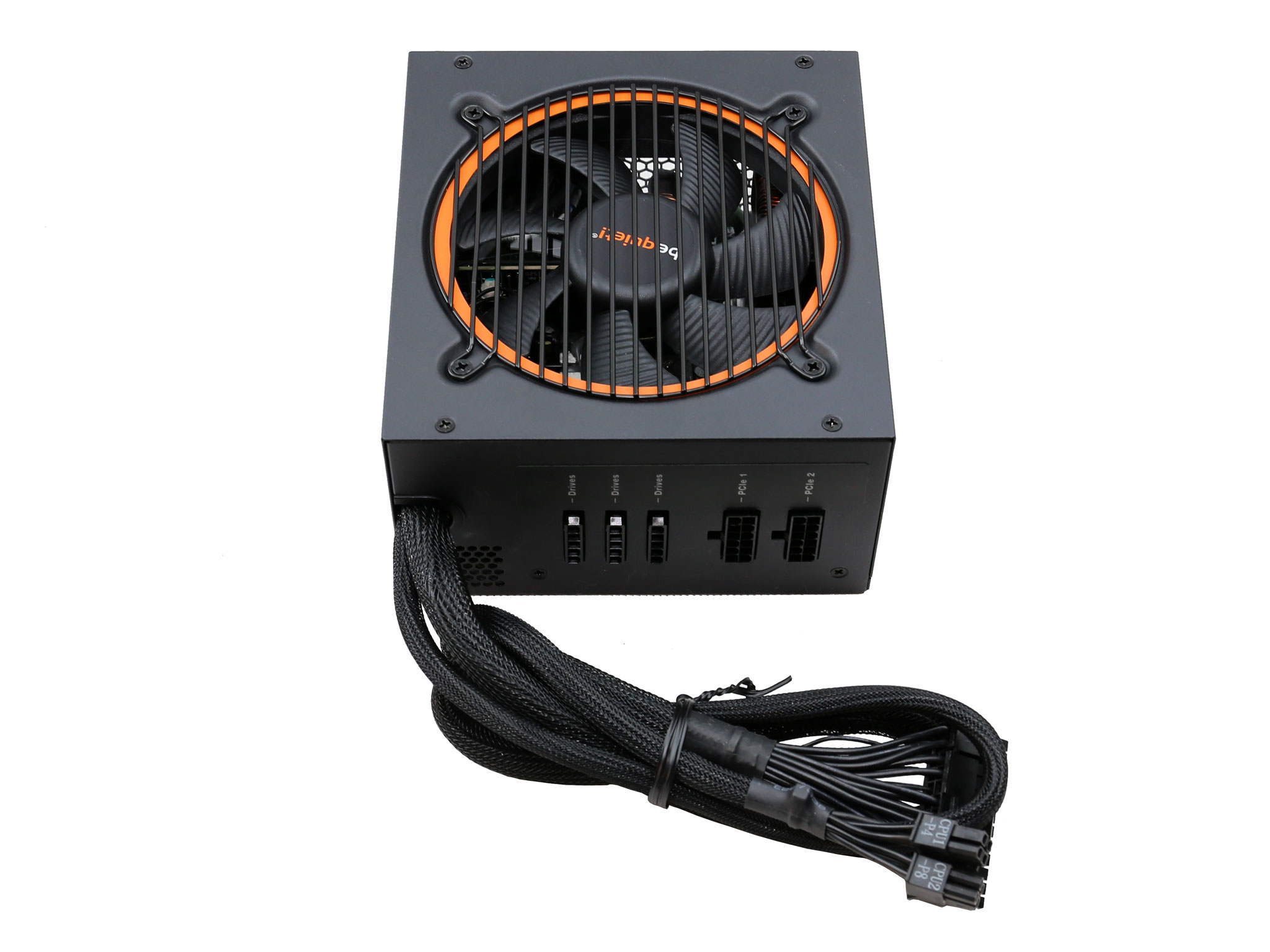
The native cables that this power supply features, besides a small number of modular ones, might look odd nowadays however this is the only way to keep the production cost low. The orange accent around the fan, its special designed blades and the nice fan grille, are the main features of this product's external design.
Read our How We Test Power Supplies HERE
Specifications
| Manufacturer (OEM) | FSP |
| Max. DC Output | 700W |
| Efficiency | 80 PLUS Gold, ETA-A (88-91%) |
| Noise | LAMBDA-A+ (15-20 dB[A]) |
| Modular | ✓ (Semi) |
| Intel C6/C7 Power State Support | ✓ |
| Operating Temperature | 0 – 40°C |
| Over Voltage Protection | ✓ |
| Under Voltage Protection | ✓ |
| Over Power Protection | ✓ |
| Over Current (+12V) Protection | ✓ |
| Over Temperature Protection | ✓ |
| Short Circuit Protection | ✓ |
| Surge Protection | ✓ |
| Inrush Current Protection | ✓ |
| Fan Failure Protection | ✗ |
| No Load Operation | ✓ |
| Cooling | 120mm Rifle Bearing Fan (BQ QF1-12025-HS) |
| Semi-Passive Operation | ✗ |
| Dimensions (W x H x D) | 152 x 87 x 162mm |
| Weight | 1.73 kg (3.81 lb) |
| Form Factor | ATX12V v2.4, EPS 2.92 |
| Warranty | 5 Years |
The max operating temperature is 40°C and according to be quiet! all necessary protection features are provided. The cooling duties are handled by a 120mm fan with a rifle bearing and strangely enough, there is no semi-passive operation. Nonetheless, from the moment the fan profile is relaxed we don't mind the lack of passive operation.
The unit's dimensions are compact with 162mm length and the weight is kept low as well. Finally, the provided warranty reaches five years which is a long period for a mid-range product.
Power Specifications
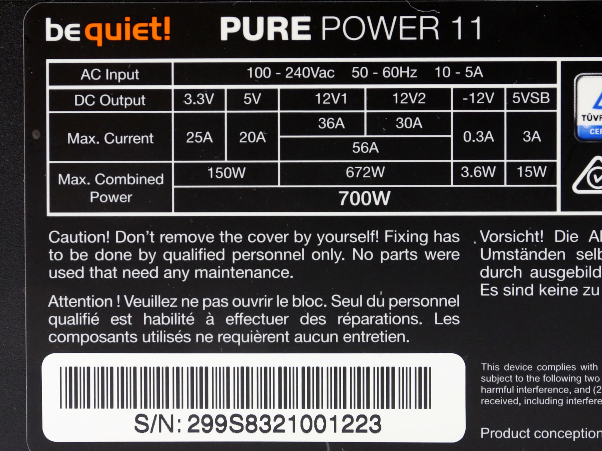
| Rail | 3.3V | 5V | 12V1 | 12V2 | 5VSB | -12V | |
| Max. Power | Amps | 25 | 20 | 36 | 30 | 3 | 0.3 |
| Watts | 150 | 56A | 15 | 3.6 | |||
| 672 | |||||||
| Total Max. Power (W) | 700 | ||||||
The minor rails have a very high maximum combined power level, given today's needs, and the pair of +12V rails cannot deliver the PSU's full power alone. This looks strange as usually in power supplies that feature DC-DC converters for the generation of the minor rails, the +12V rail has the same capacity as the unit's maximum power.
The 5VSB rail is a bit stronger than the usual, with 3 Amps max current output.
Cables & Connectors
|
Native Cables
|
||||
|
Description
|
Cable Count
|
Connector Count (Total)
|
Gauge
|
In Cable Caps
|
|
ATX connector 20+4 pin (550mm)
|
1
|
1
|
18-24AWG
|
No
|
|
4+4 pin EPS12V (600mm)
|
1
|
1
|
18AWG
|
No
|
|
Modular Cables
|
||||
|
Description
|
Cable Count
|
Connector Count (Total)
|
Gauge
|
Gauge
|
|
6+2 pin PCIe (500mm+150mm)
|
2
|
4
|
18AWG
|
No
|
|
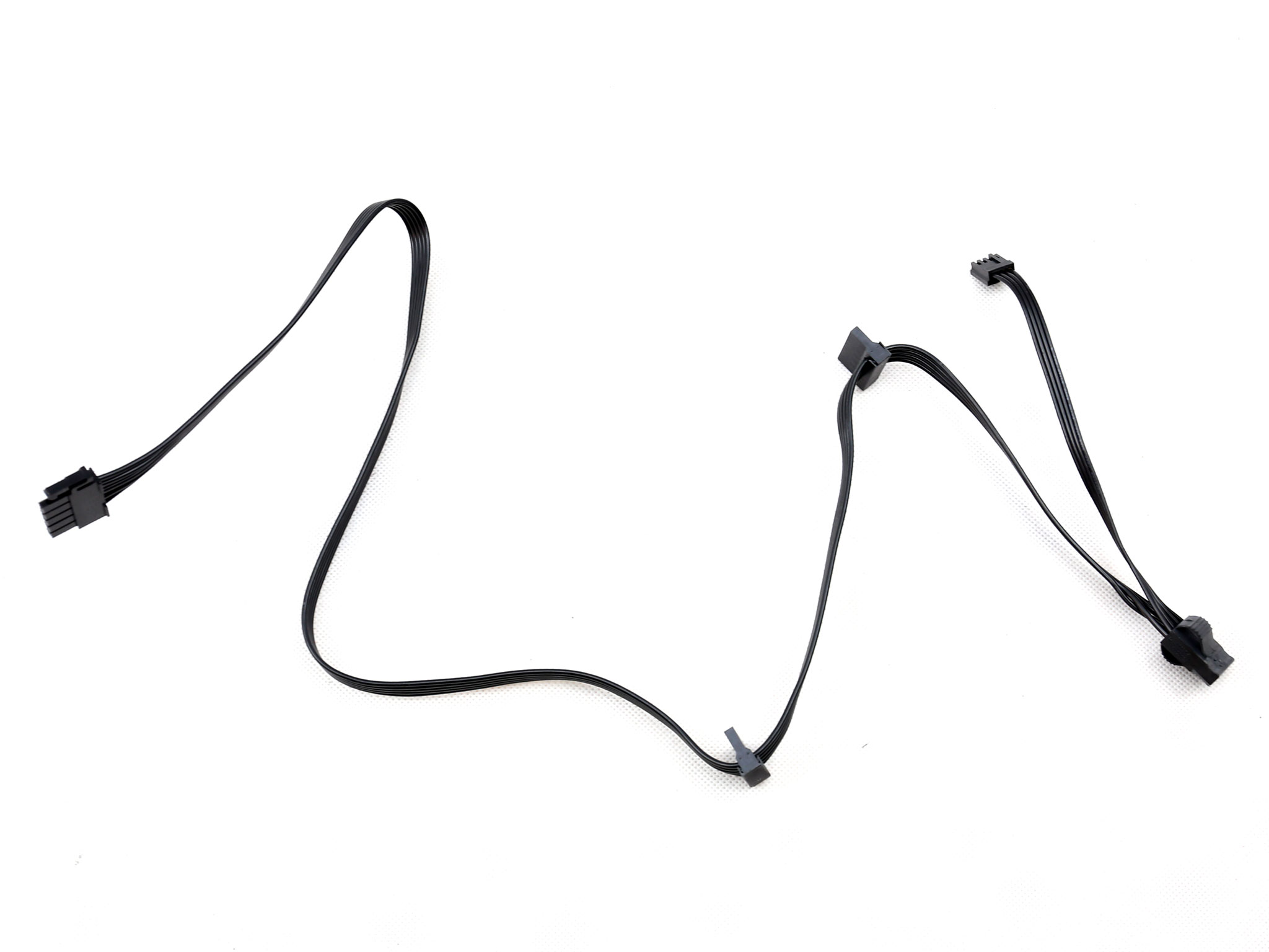
SATA (500mm+150mm+150mm)
|
1
|
3
|
18AWG
|
No
|
|
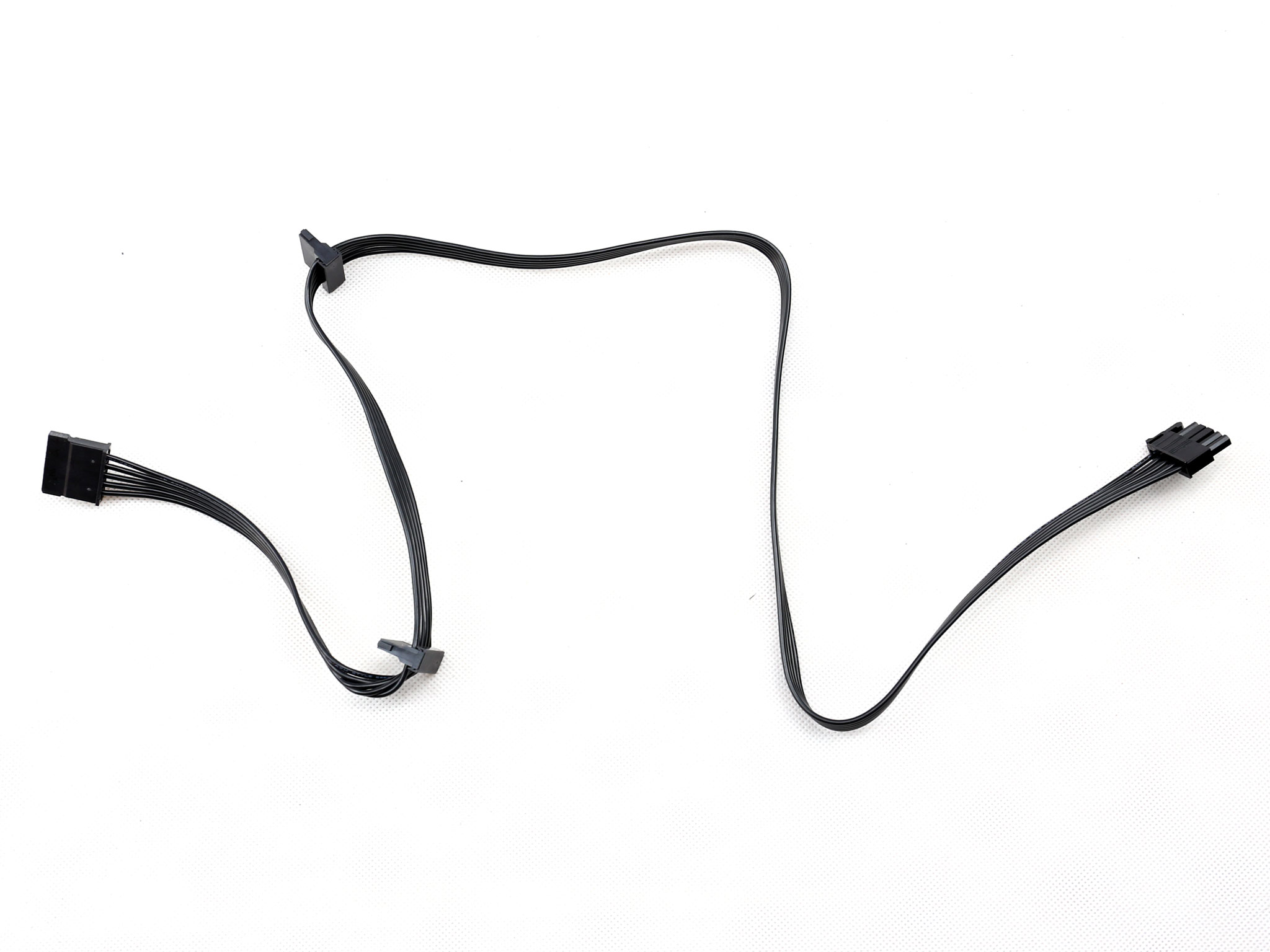
SATA (500mm) / 4-pin Molex (+150mm+150mm)
|
1
|
1 / 2
|
18AWG
|
No
|
|
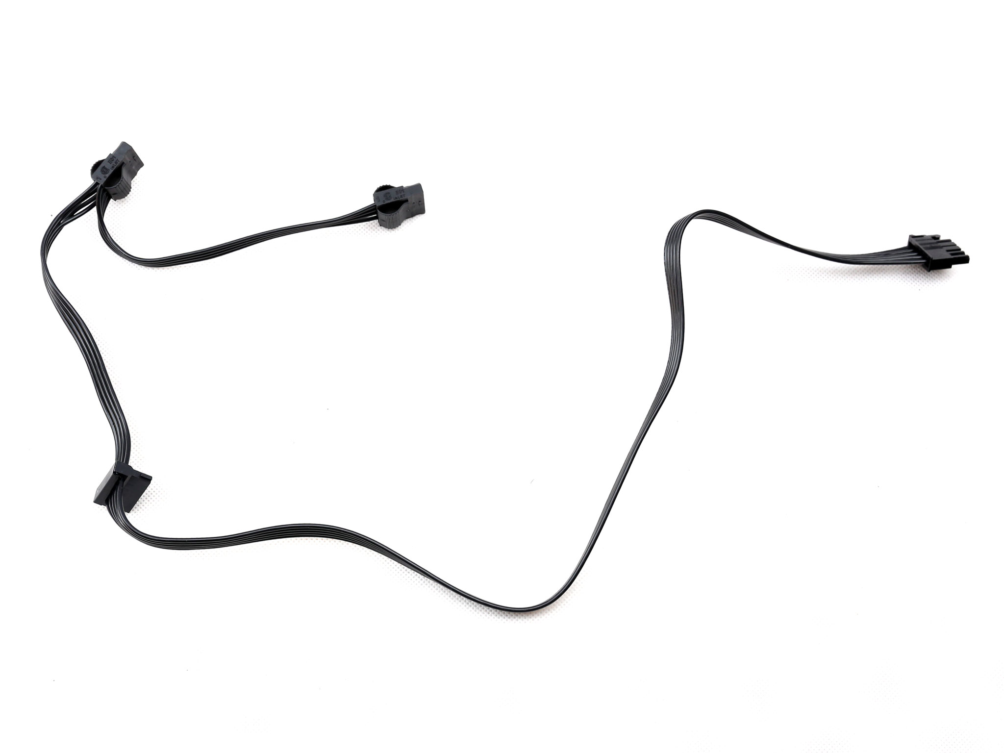
SATA (500mm+150mm) / 4-pin Molex (+150mm) / FDD (+150mm)
|
1
|
2 / 1 / 1
|
18-22AWG
|
No
|
|
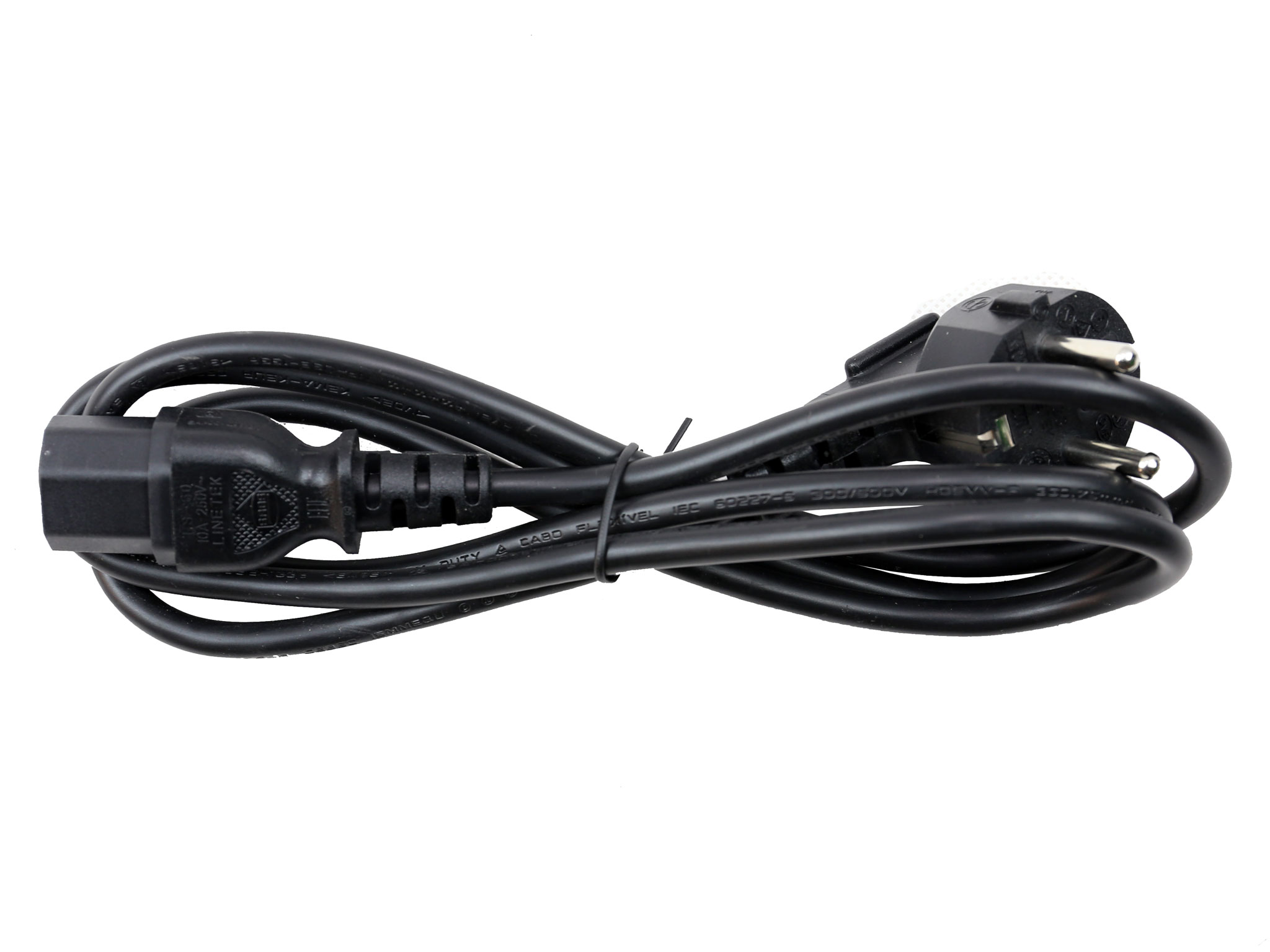
AC Power Cord (1360mm)
|
1
|
1
|
18AWG
|
–
|
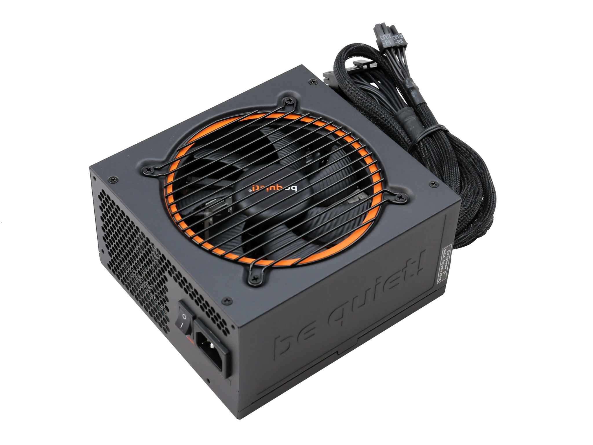
The absolutely necessary cables are fixed, with all the rest being modular. All cables have sufficient length, considering that usually a budget-oriented power supply is not combined with a huge full tower chassis, and the number of connectors is satisfactory.
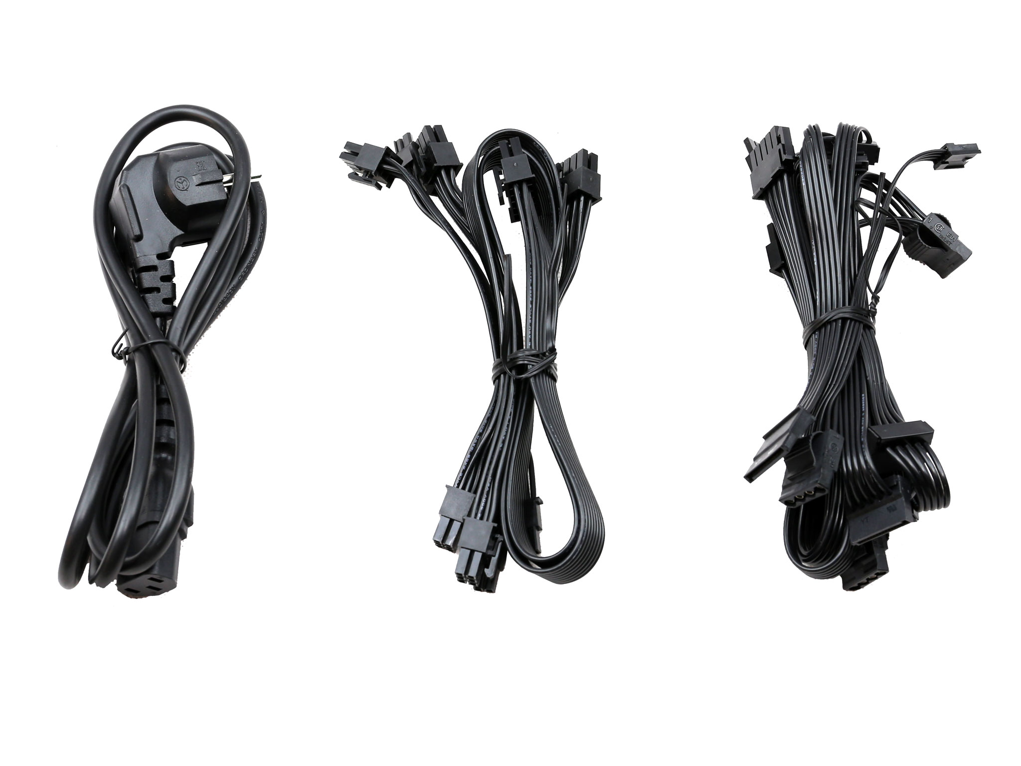
We would like to see of course a second EPS connector, but according to be quiet! this is a mainstream product so we cannot be too hard on them.
The distance between the connectors, in cables that have more than one, is adequate at 150mm. The only problem that we spot here is the fixed FDD connector. In our opinion this connector should be provided through an adapter (4-pin Molex to FDD), since most users won't even need it.
Power Distribution
|
Power Distribution |
|
|
12V1 |
ATX, Peripheral, SATA, PCIe2 (Left) |
|
12V2 |
PCIe1 (Right), EPS |
This unit has two +12V rails and the power distribution is not optimal, since the second +12V rail mixes one of the PCIe sockets with the single EPS connector. Normally none of the PCIe sockets should be on the same rail with the EPS cable.
Packaging
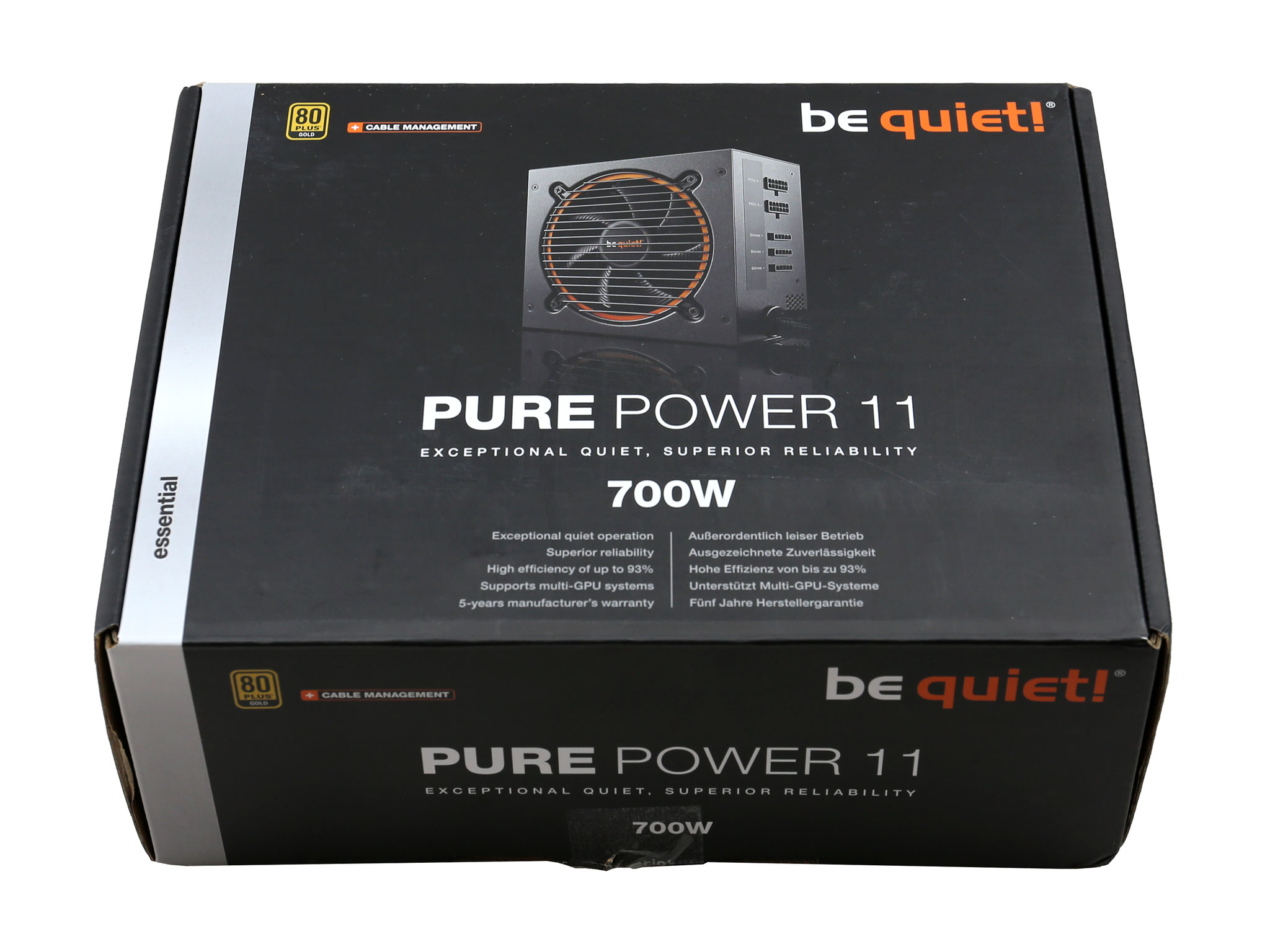
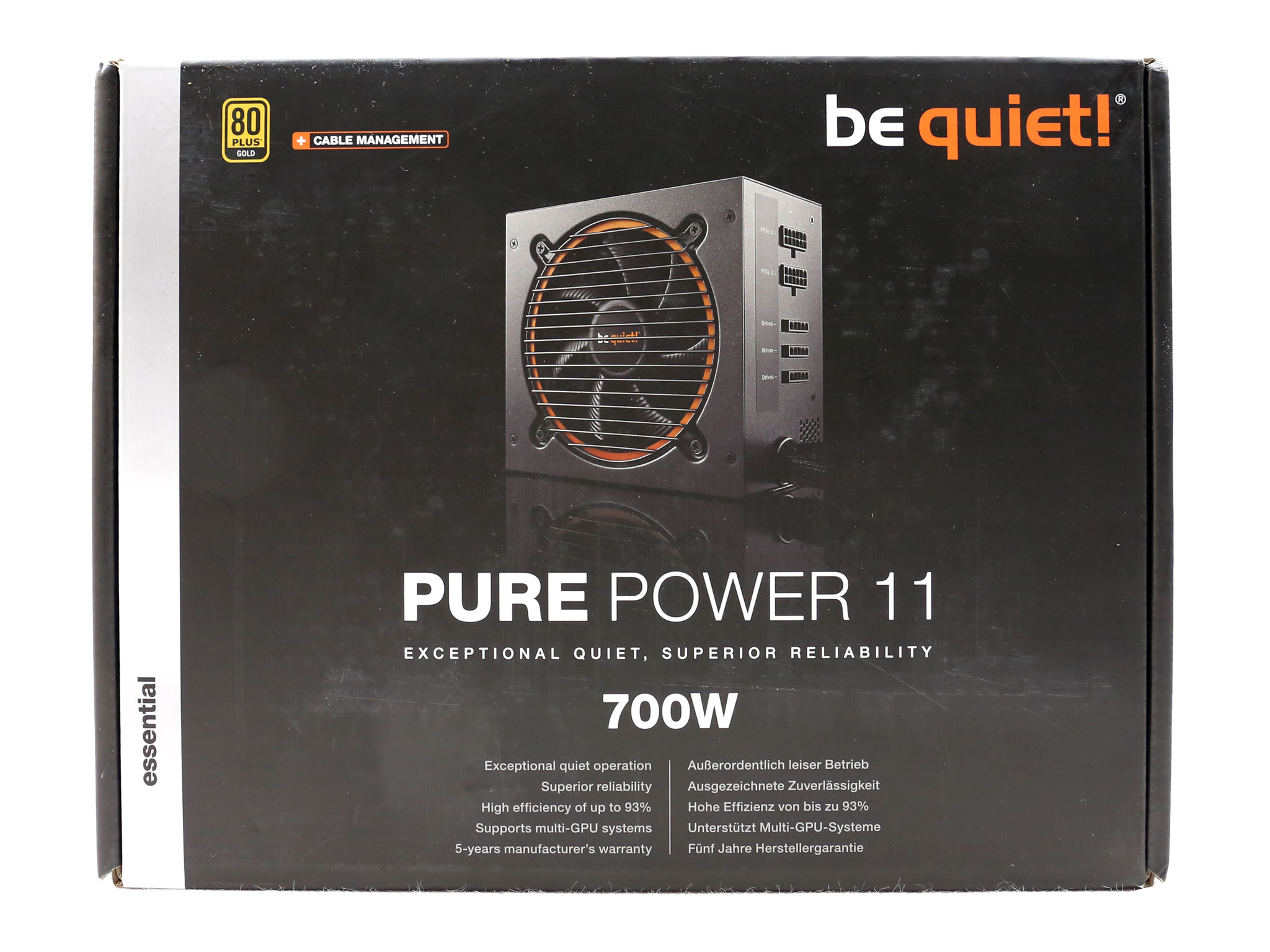
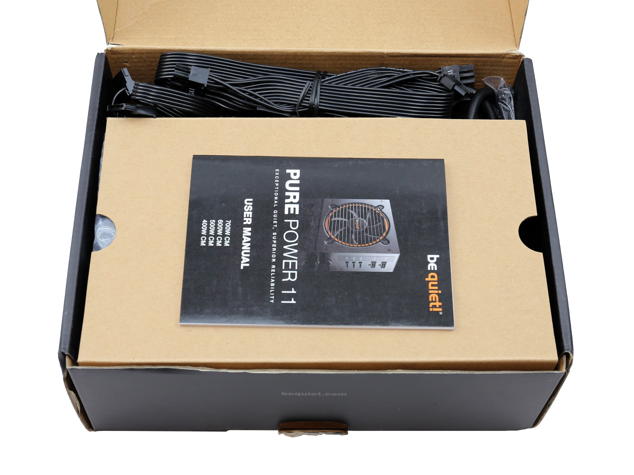
The box is small and at the front there is a photo of the product, with the semi-modular panel shown. The series description is highlighted in large fonts and below it we find the unit's capacity. The small 80 PLUS Gold badge is near the top-left corner.
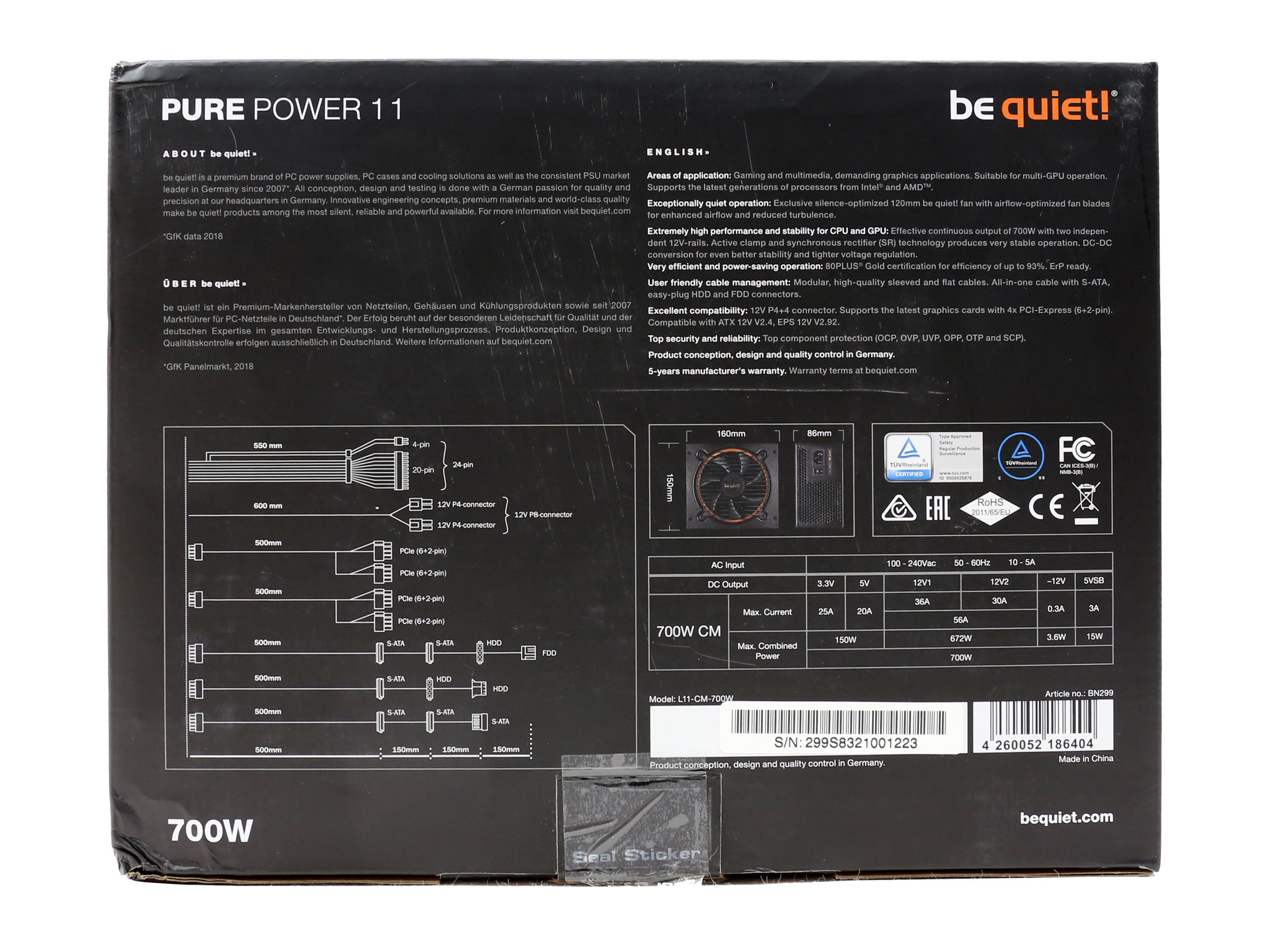
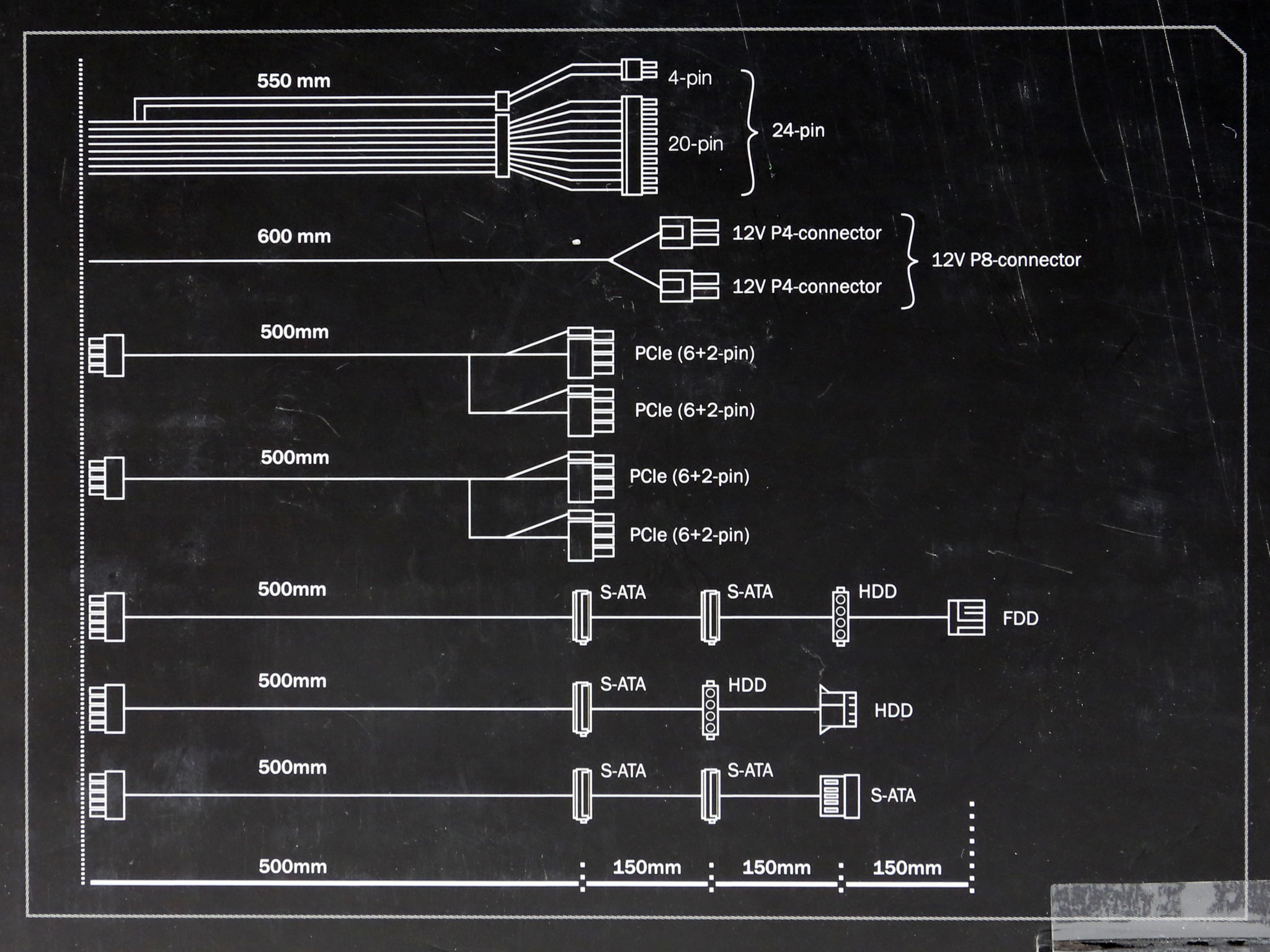
At the rear be quiet! gives information showing the length of both native and modular cables and the number of the respective connectors.
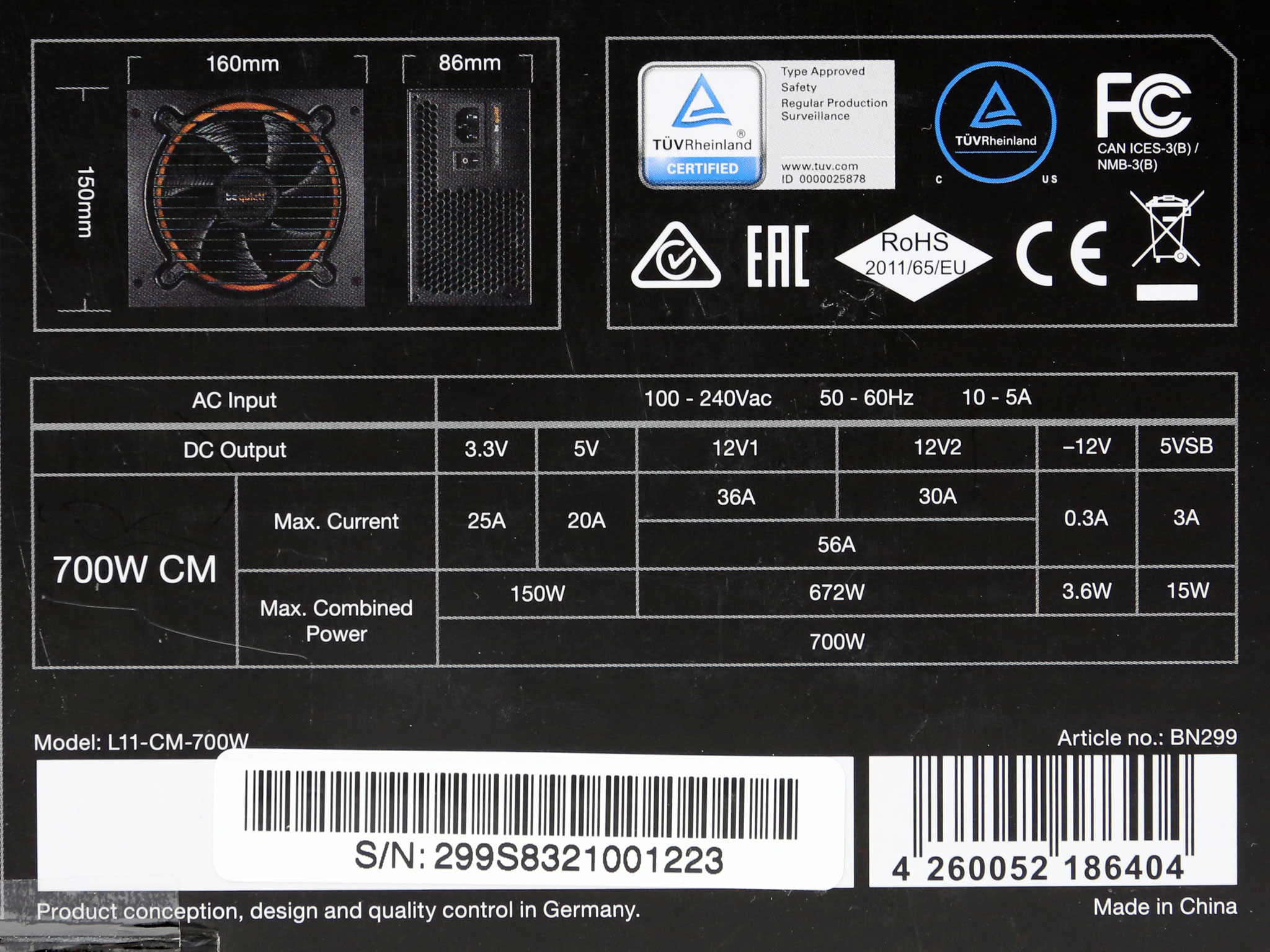
Another image highlights the unit's dimensions and here you will also find the power specifications table, the various certifications that the product has achieved. There are also a couple of stickers with one of them listing the serial number.
Contents
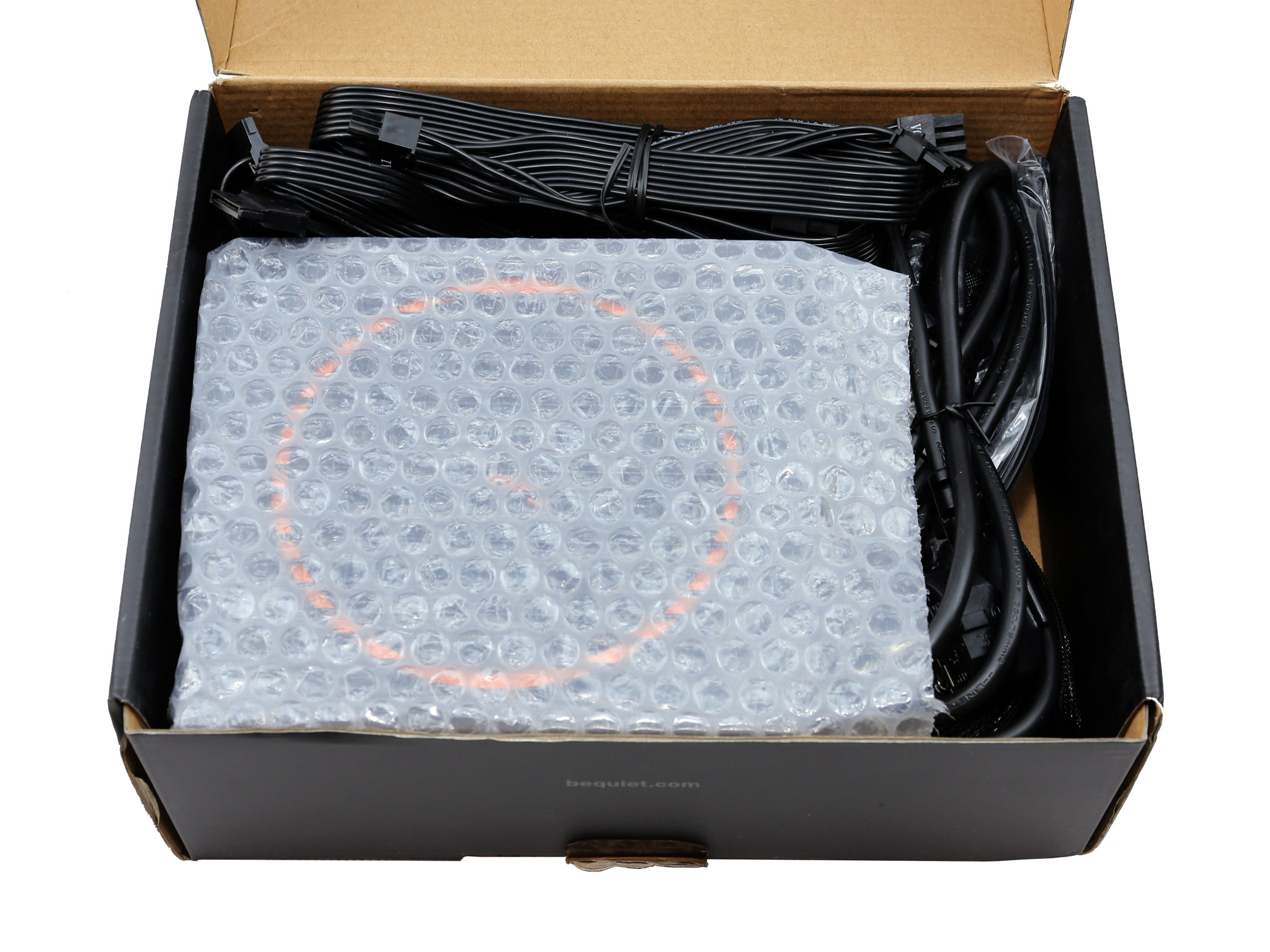
We cannot say that the protection inside the box is the best possible, since only a little bubble wrap is used. We would like to see packing foam used instead.
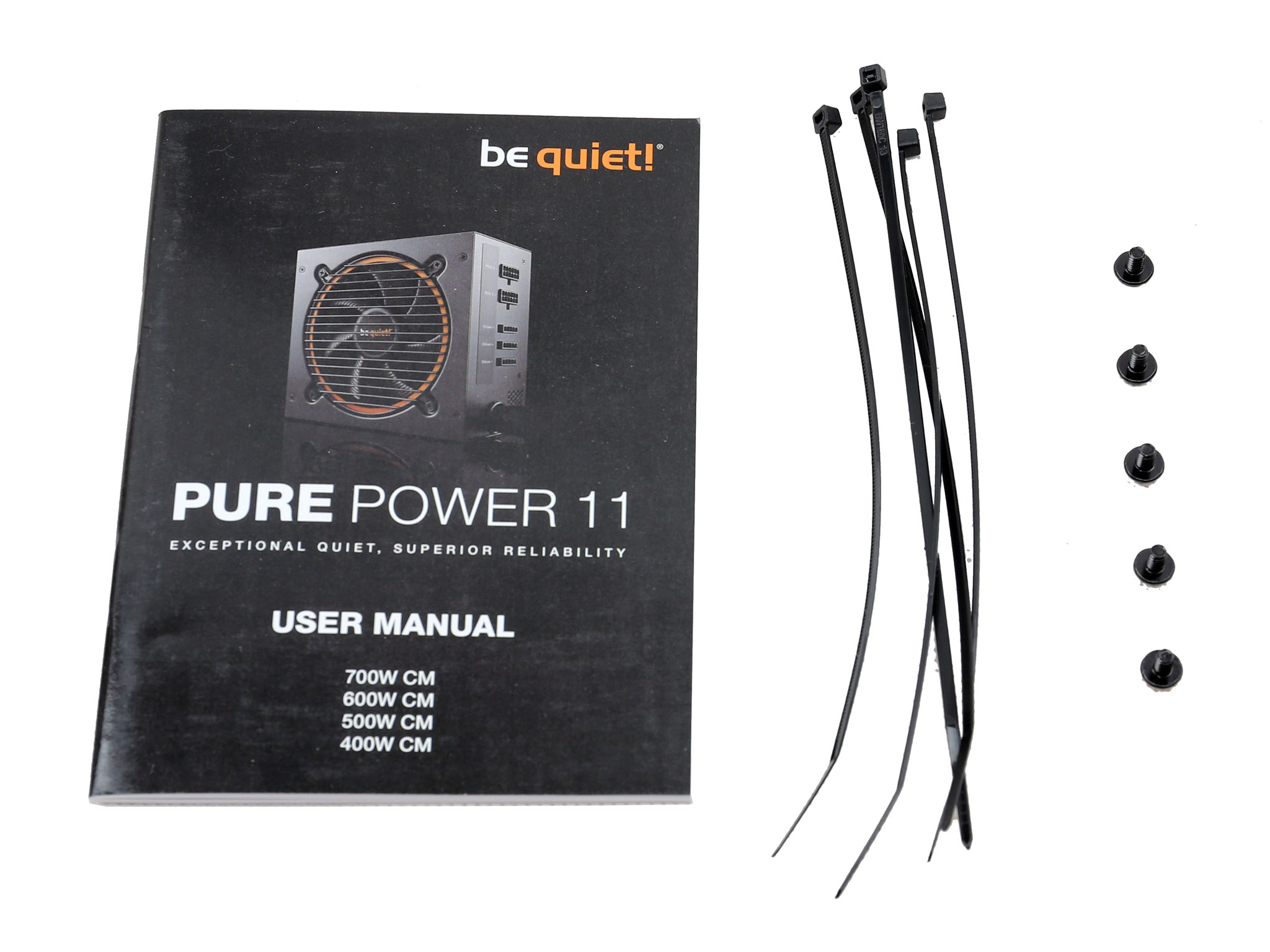
The bundle includes five screws, the user's manual and a set of zip ties.
Exterior
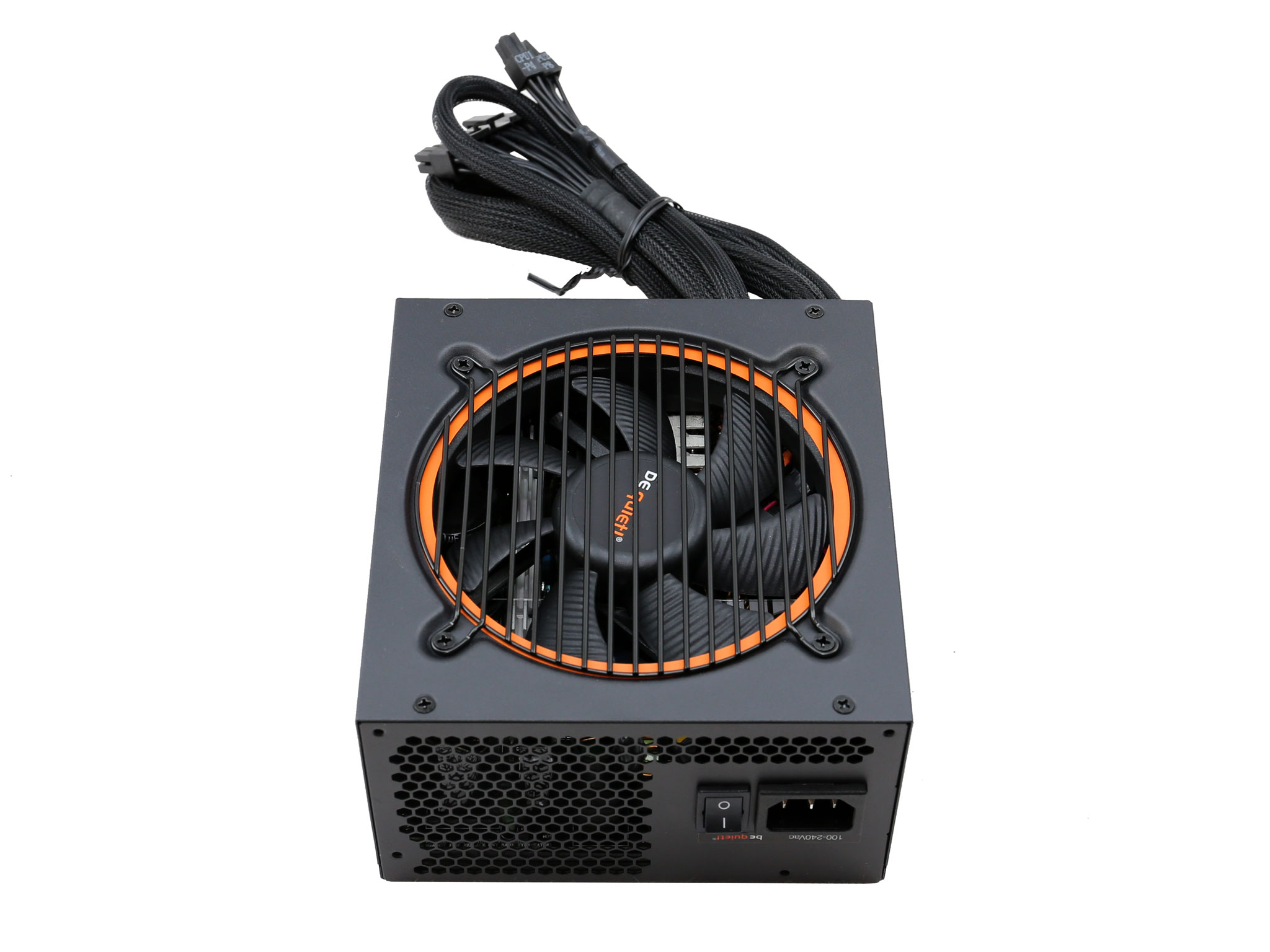
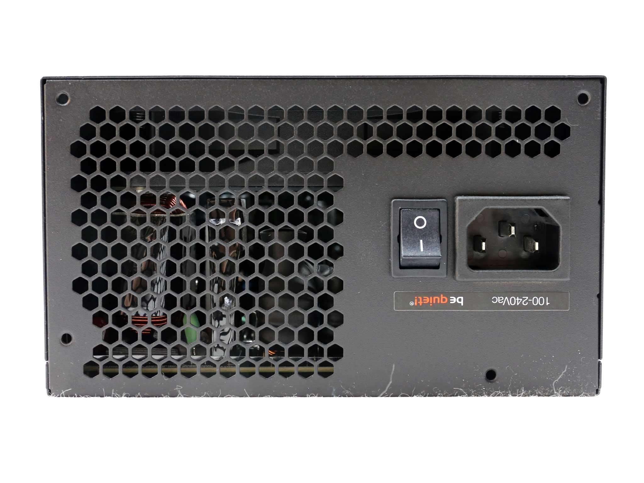
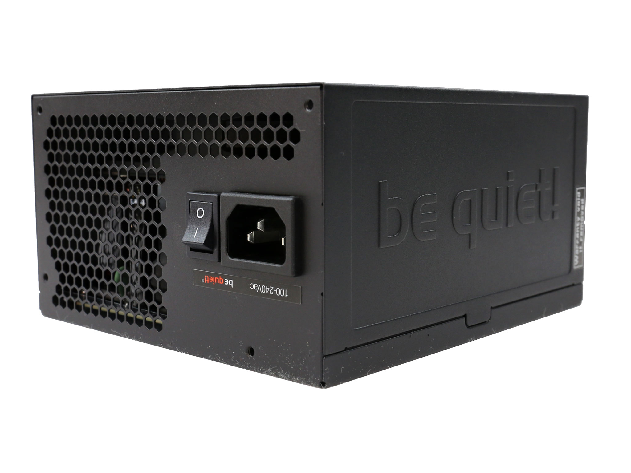
The front exhaust grille is not optimized for high airflow, since a major part of it doesn't feature any ventilation holes. The power switch is located right next to the AC receptacle.
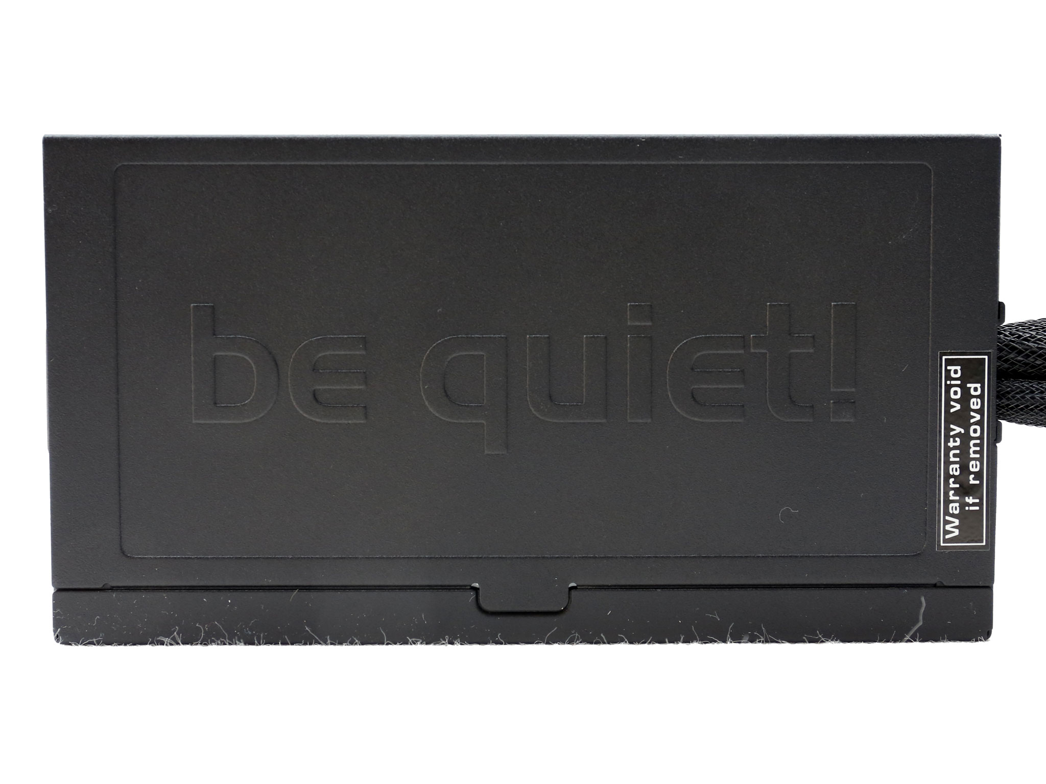
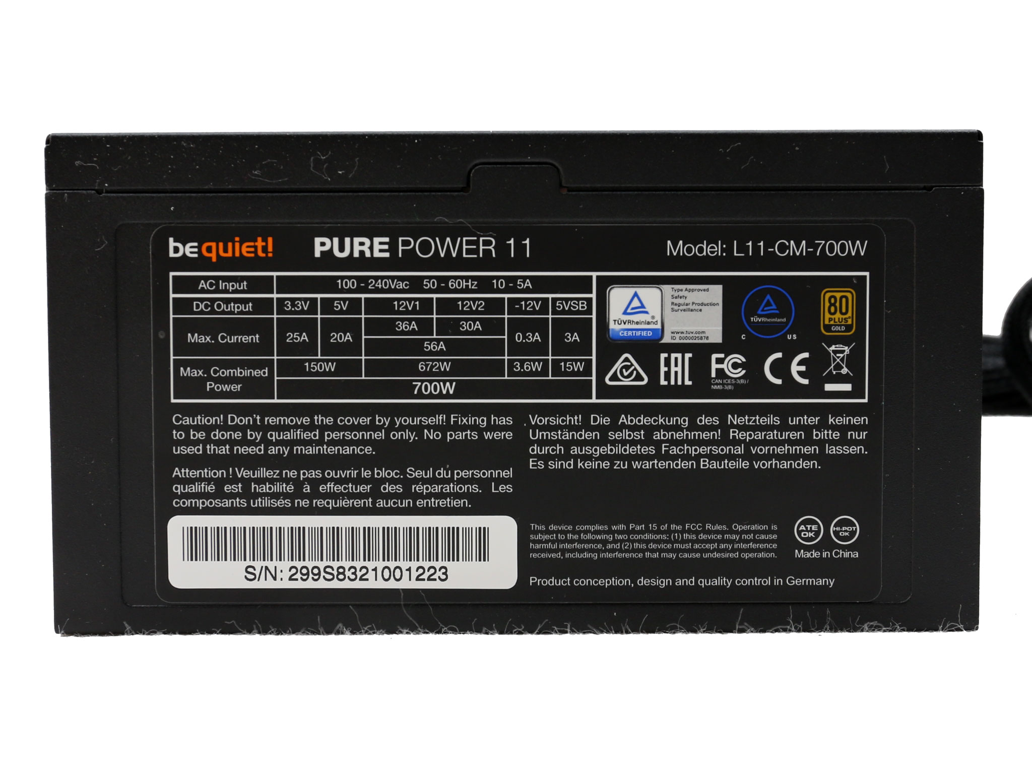
On one of the two sides we find a stamped be quiet! logo along with the warranty sticker, while on the other side is the large power specifications label, which also depicts the product's serial number.
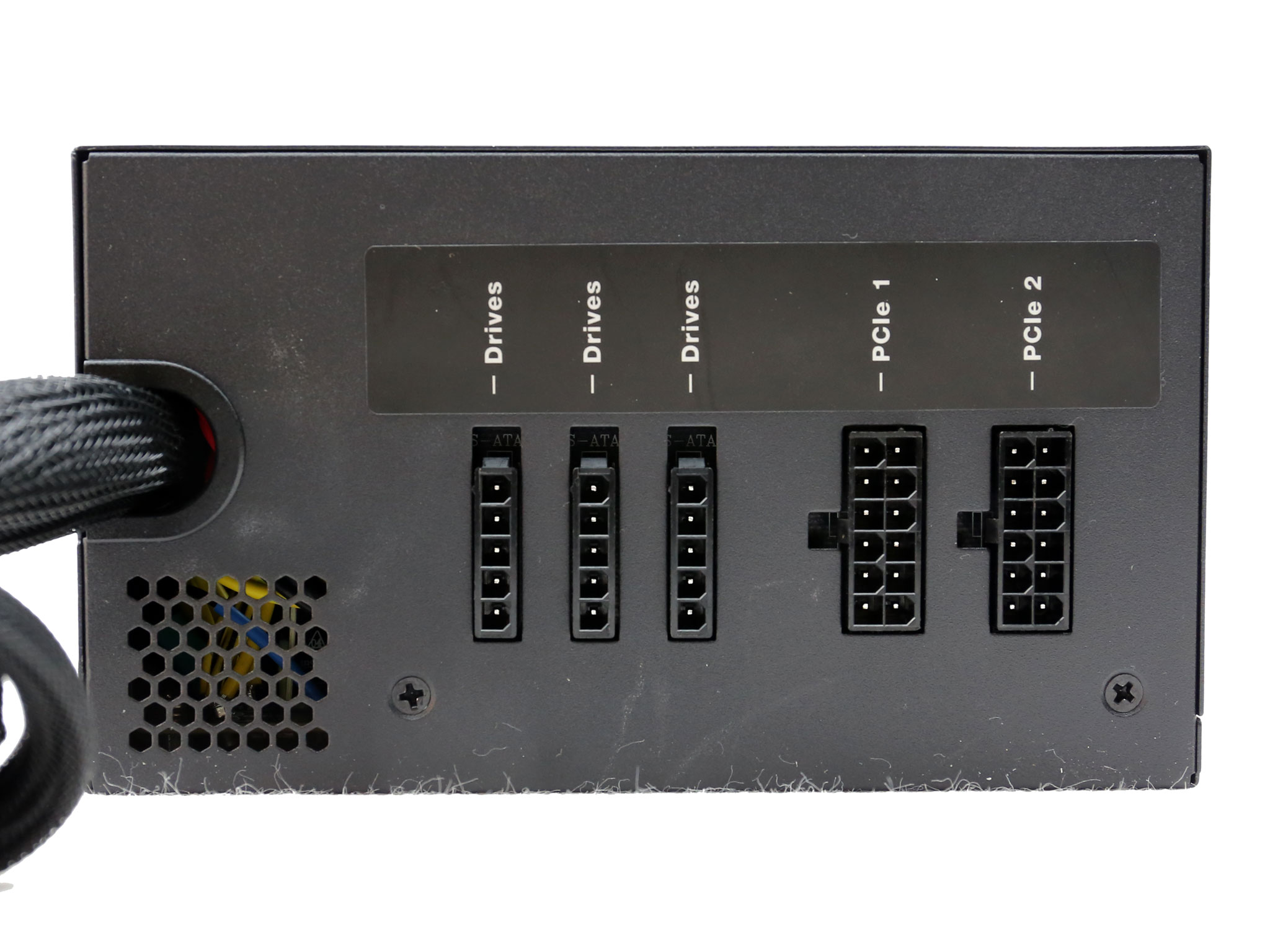
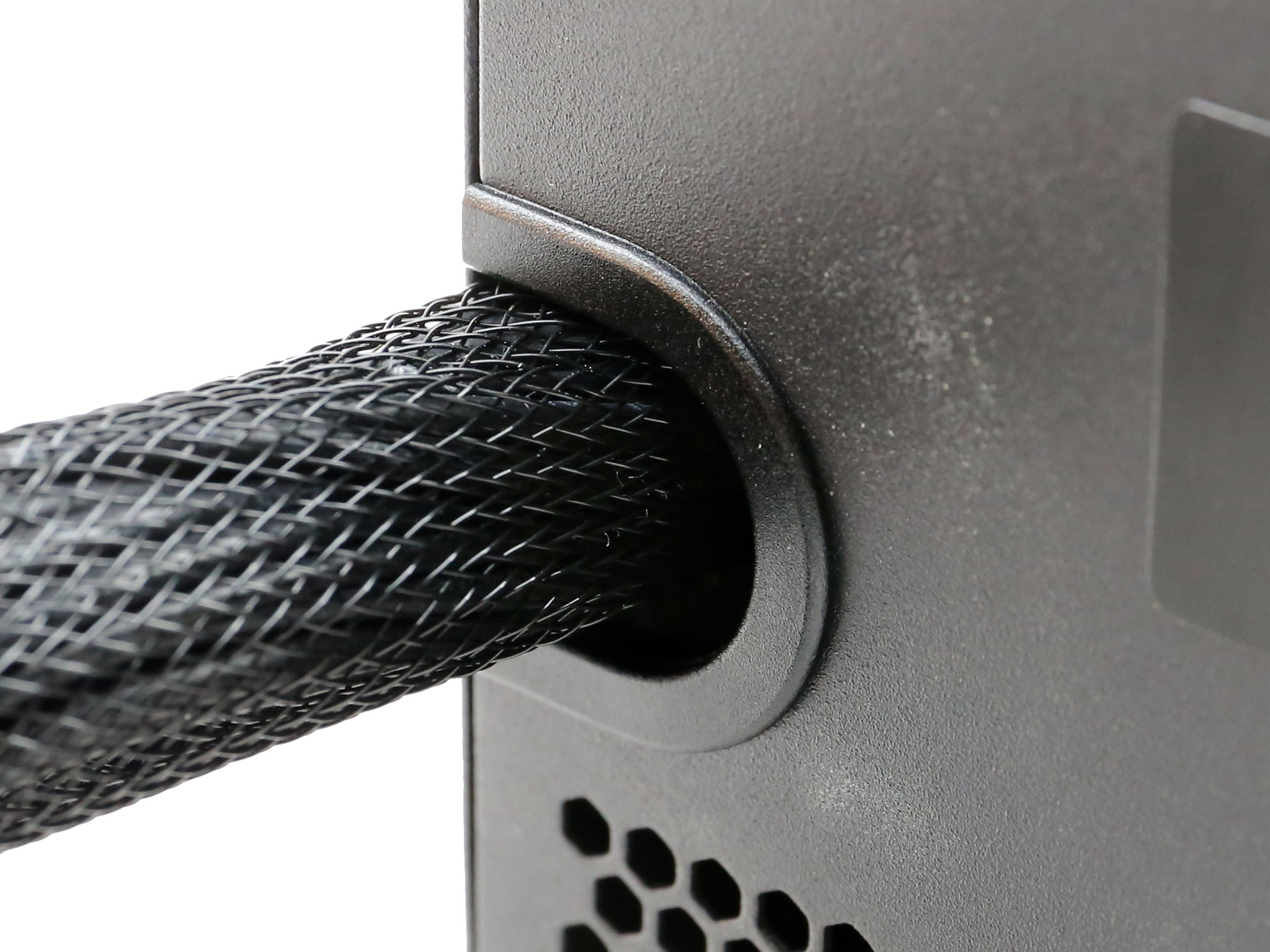
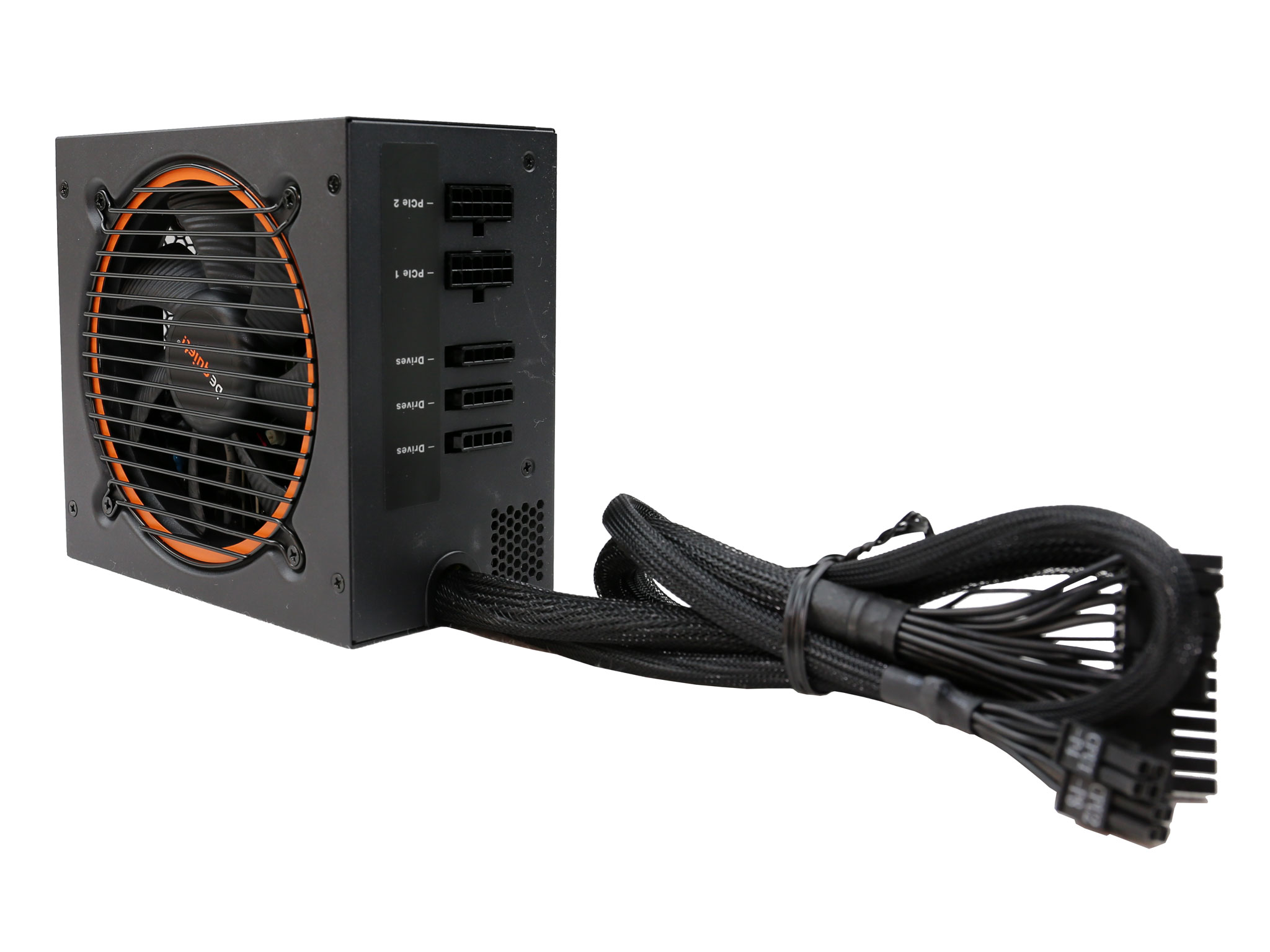
The modular panel only has five sockets, since two cables are fixed. Finally, there is a plastic grommet around the cable exit hole, to protect them from the chassis edges.
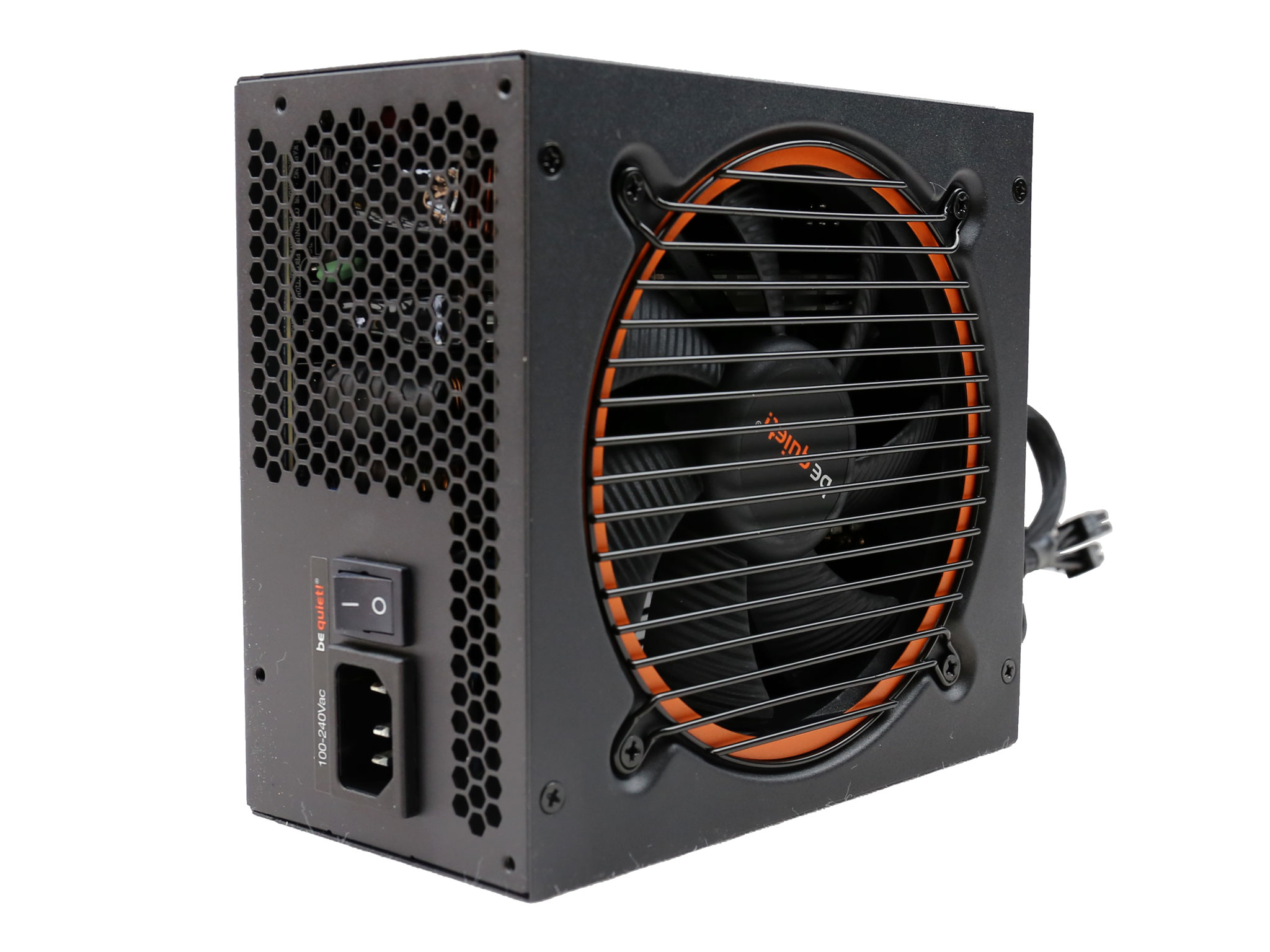
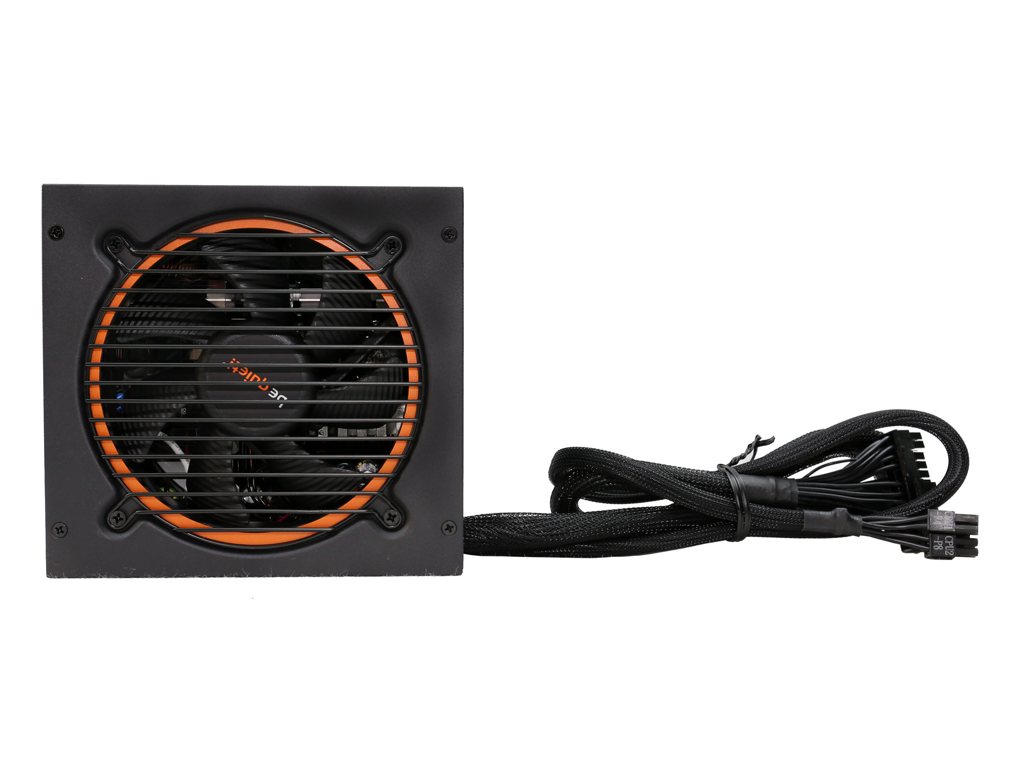
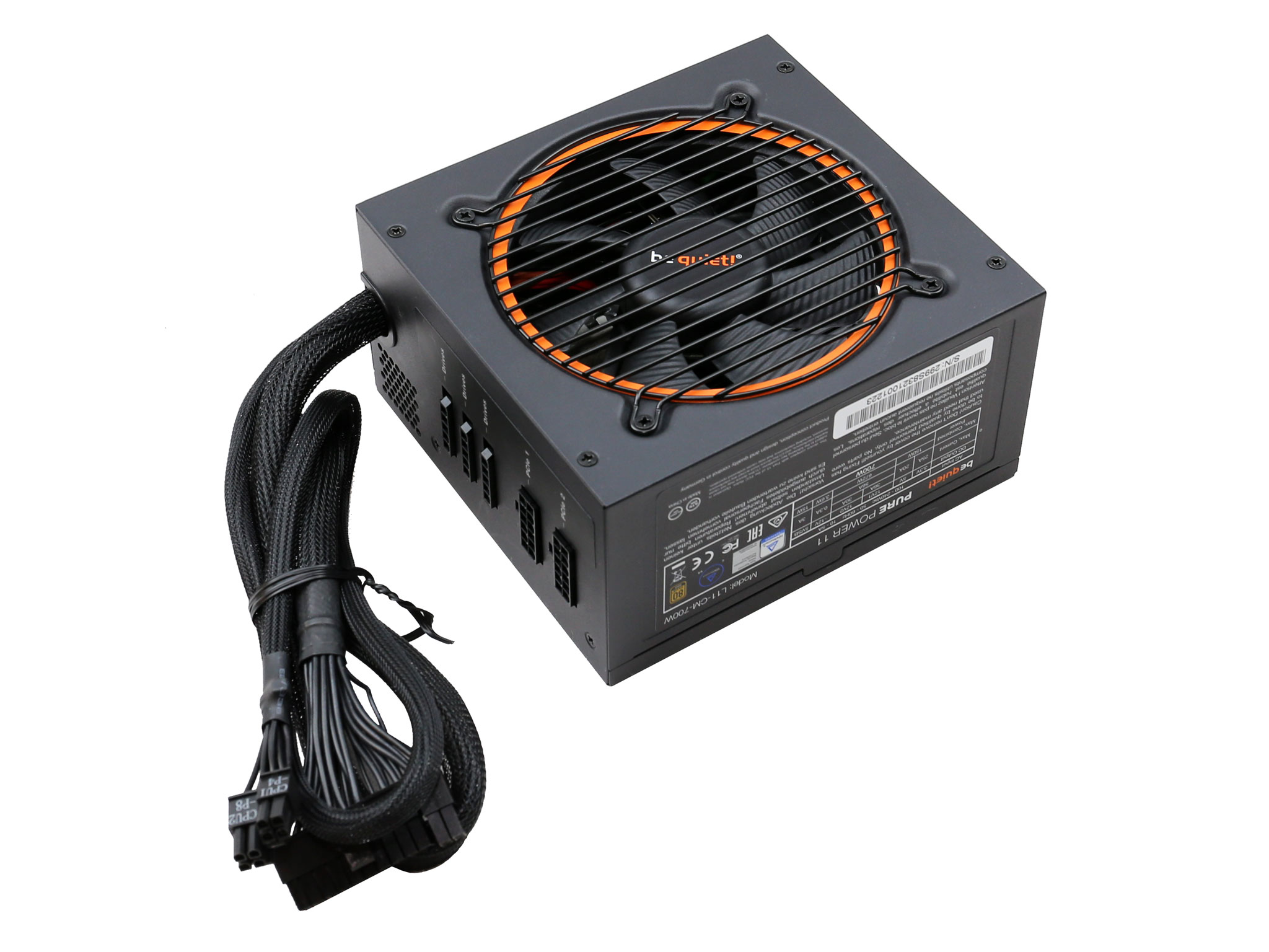
The dimensions are compact and the looks is distinctive, thanks to the orange accent around the fan and the minimalist-design fan grille.
| General Data | |
| Manufacturer (OEM) | FSP |
| Platform Model | Raider |
| Primary Side | |
| Transient Filter | 4x Y caps, 2x X caps, 2x CM & 1 DM chokes, 1x GTD |
| Inrush Protection | NTC Thermistor |
| Bridge Rectifier(s) |
1x
|
| APFC MOSFETS |
2x Infineon IPA60R190P6 (650V, 12.7A @ 100°C, 0.19Ω)
|
| APFC Boost Diode |
1x STMicroelectronics STTH8R06FP (600V, 8A @ 130°C)
|
| Hold-up Cap(s) |
1x Teapo (420V, 390uF, 2000h @ 85°C, LH)
|
| Main Switch |
1x STMicroelectronics STF25N80K5 (800V, 12.3A @ 100°C, 0.26Ω)
|
| Reset Switch |
1x CET CEF03N8 (800V, 2A @ 100°C, 4.8Ω)
|
| Combo APFC/PWM Controller |
FSP 6600 IC
|
| Topology |
Primary side: Active Clamp Reset Forward
Secondary side: Synchronous Rectification & DC-DC converters |
| Secondary Side | |
| +12V MOSFETS | 2x |
| 5V & 3.3V | DC-DC Converters: 4x Infineon IPD031N03L G (30V, 90A @ 100°C, 3.1mΩ) PWM Controller: 2x FSP6601 |
| Filtering Capacitors | Electrolytics: 8x Teapo SC (1-3,000 @ 105°C, SC), 4x Teapo SY (3-6,000 @ 105°C) Polymers: 5x CapXon (modular board), 1x Teapo (-12V board) |
| Supervisor IC | Weltrend WT7527 (OVP, UVP, OCP, SCP, PG) |
| Fan Model | BQ QF1-12025-HS (120mm, 12V, 0.30A, 2000 RPM, Rifle Bearing) |
| 5VSB Circuit | |
| Rectifier FET |
CET CEF02N7G (700V, 1.3A @ 100°C, 6.75Ω)
|
| Rectifier SBR | 1x PS30U60CTR |
| -12V Circuit | |
| Rectifier IC |
7912
|
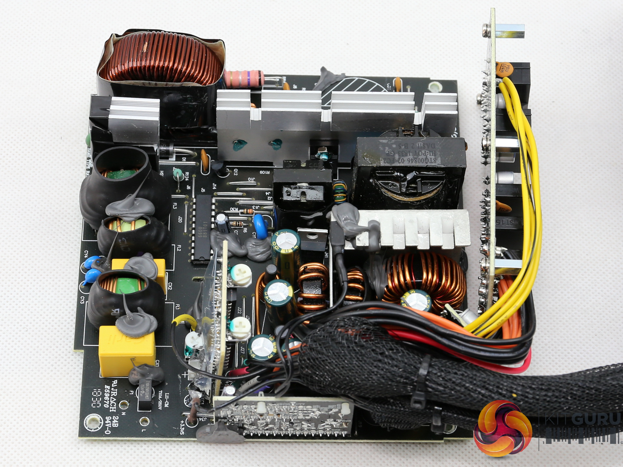
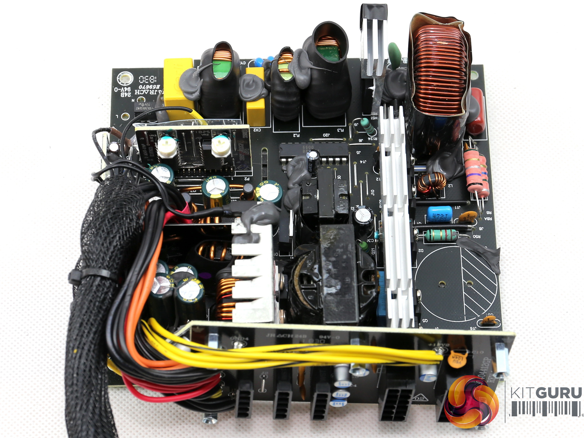
This is FSP's Raider platform, which is more budget than performance oriented. At the primary side it uses an Active Clamp Reset Forward (ACRF) topology which offers high efficiency without needing extra components such as an LLC resonant converter.
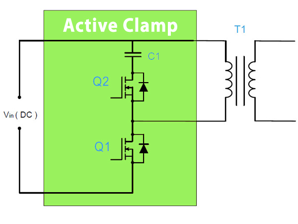
In low capacity ACRF platforms a couple of FETs are used with one of them being the main switcher (Q1), while the other one is the reset switch (Q2) which disconnects the clamp capacitor when Q1 is active.
The power is transferred from the primary to the secondary side only when the Q2 FET is active. This topology allows for an almost lossless switching of the Q1 FET, since while it is off the drain voltage is very low.
The second major advantage of the ACRF topology is the long hold-up time that it provides, even with low capacity bulk caps. Since those caps are among the most expensive parts of a power supply, the savings are notable.
The scheme below shows an ACRF design. When Q1 is active voltage runs through the T1 transformer, so there is power transfer from the primary side to the secondary one. When the Q2 FET is active, clamp voltage is applied to T1.
As C1's capacity increases, the ripple voltage gets lower however a high capacity C1 affects the transient response, so a good engineer has to find the optimal balance between ripple and performance under transient loads.
The major breakthrough in the Pure Power line was made last year since the Pure Power 10 models were equipped with DC-DC converters, for the generation of the minor rails. The previous units used a group-regulation scheme which tied the +12V and 5V rails together, with only the 3.3V rail being independently regulated.
Finally, from the Pure Power 10 line FSP started (finally) to use NTC thermistors to restrict the large inrush currents that occur during the start-up phase.
![]()
![]()
![]()
![]()
![]()
![]()
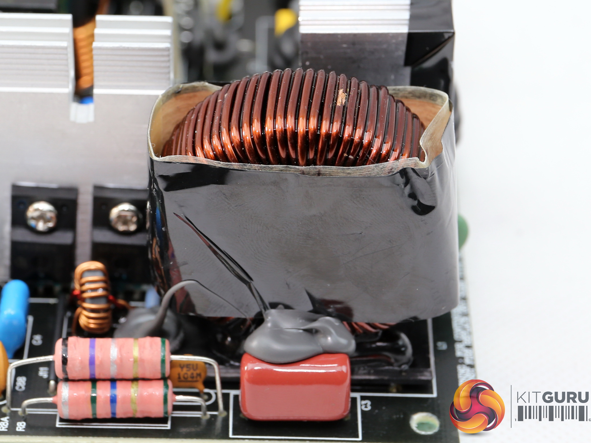
The first part of the EMI filter consists of two Y and one X caps. The second part, on the main PCB, includes the same amount of Y and X caps, two CM chokes, a single DM choke and a Gas Discharge Tube (GDT) instead of an MOV.
We would prefer to see the latter component being used, since it has faster response and good overall clamping performance. The only problem with MOVs is that repeated surges cause wear and while clamping the voltage rises along with surge current.
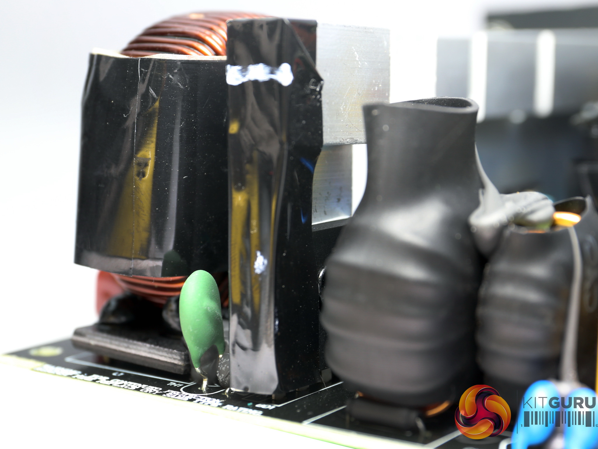
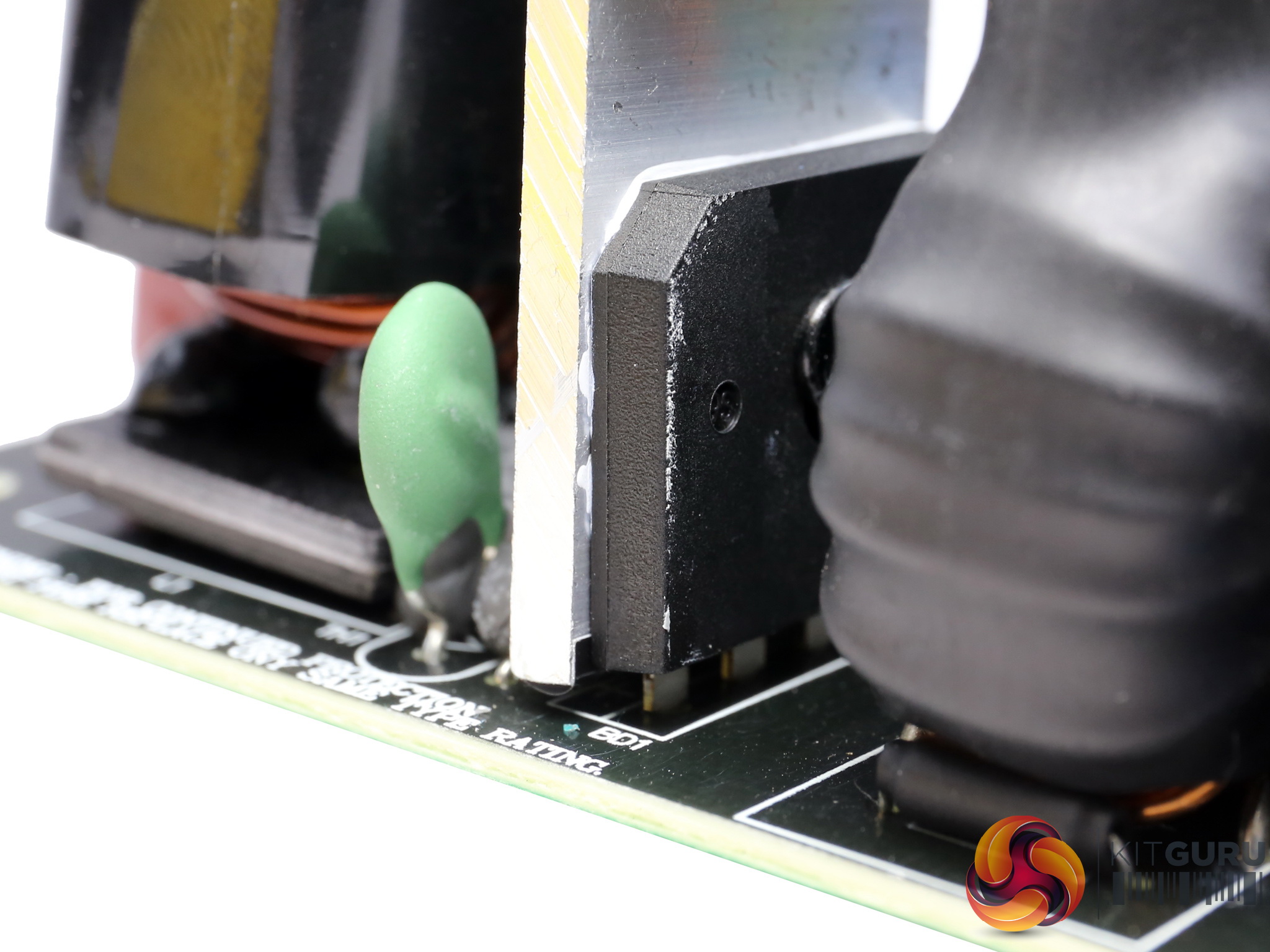
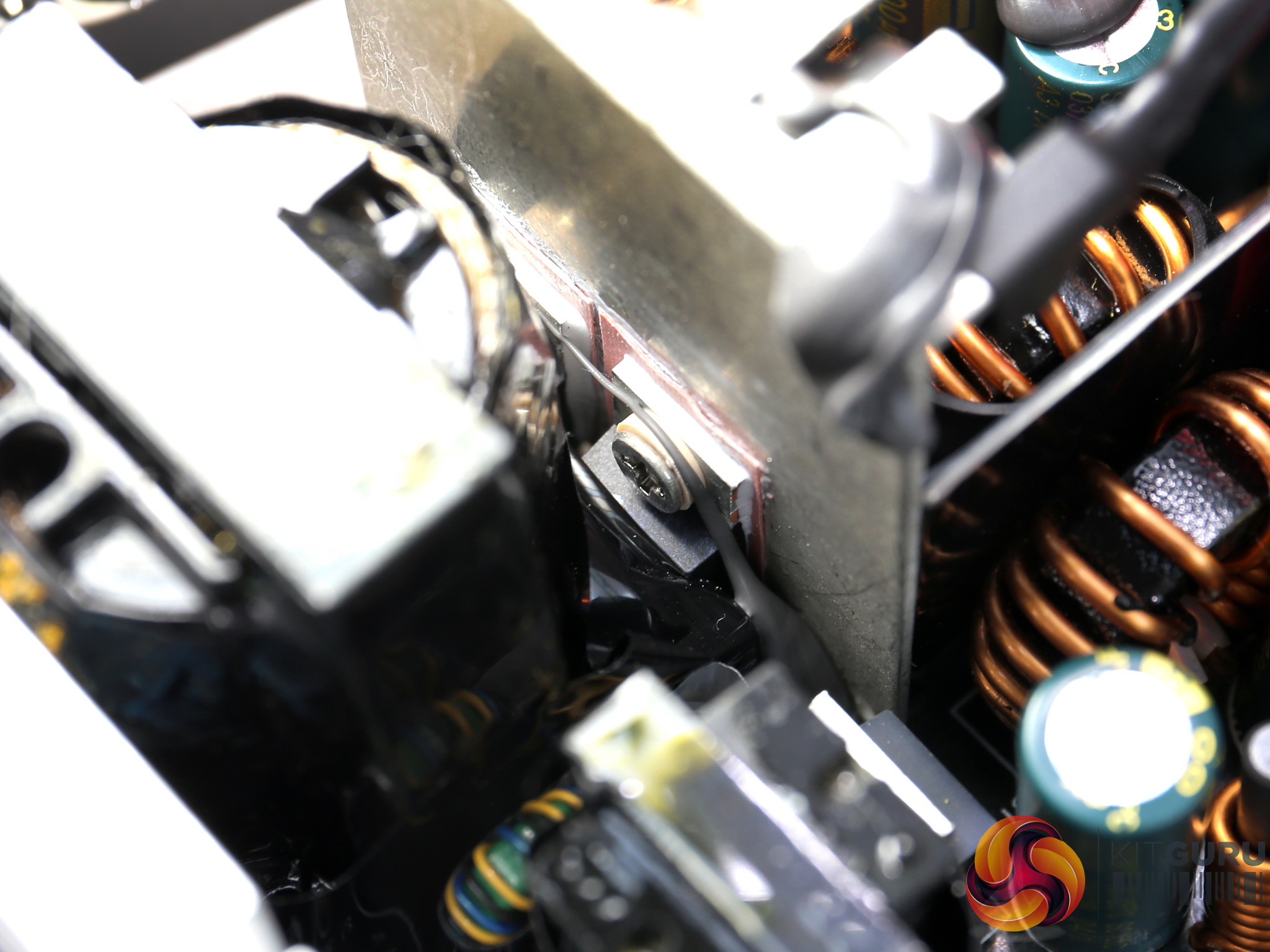
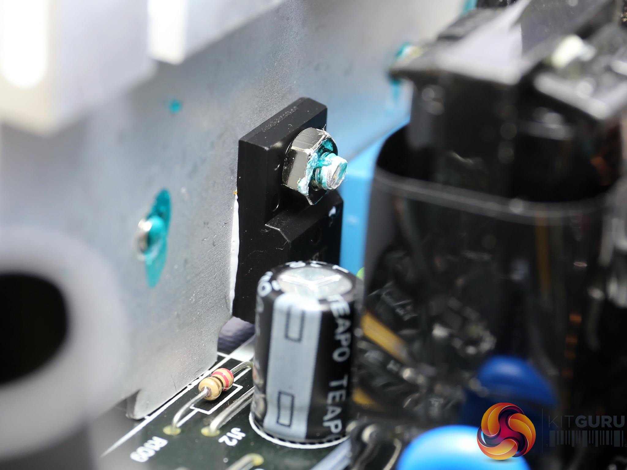
The single bridge rectifier is bolted onto a dedicated heatsink. We cannot make out its model number without desoldering it, something that we want to avoid since those parts are very sensitive to high temperatures.
Next to the bridge's heatsink is a small NTC thermistor, responsible for protection against large inrush currents. Unfortunately FSP didn't use a bypass relay, to restrict energy losses and allow for the thermistor's fast cool down.
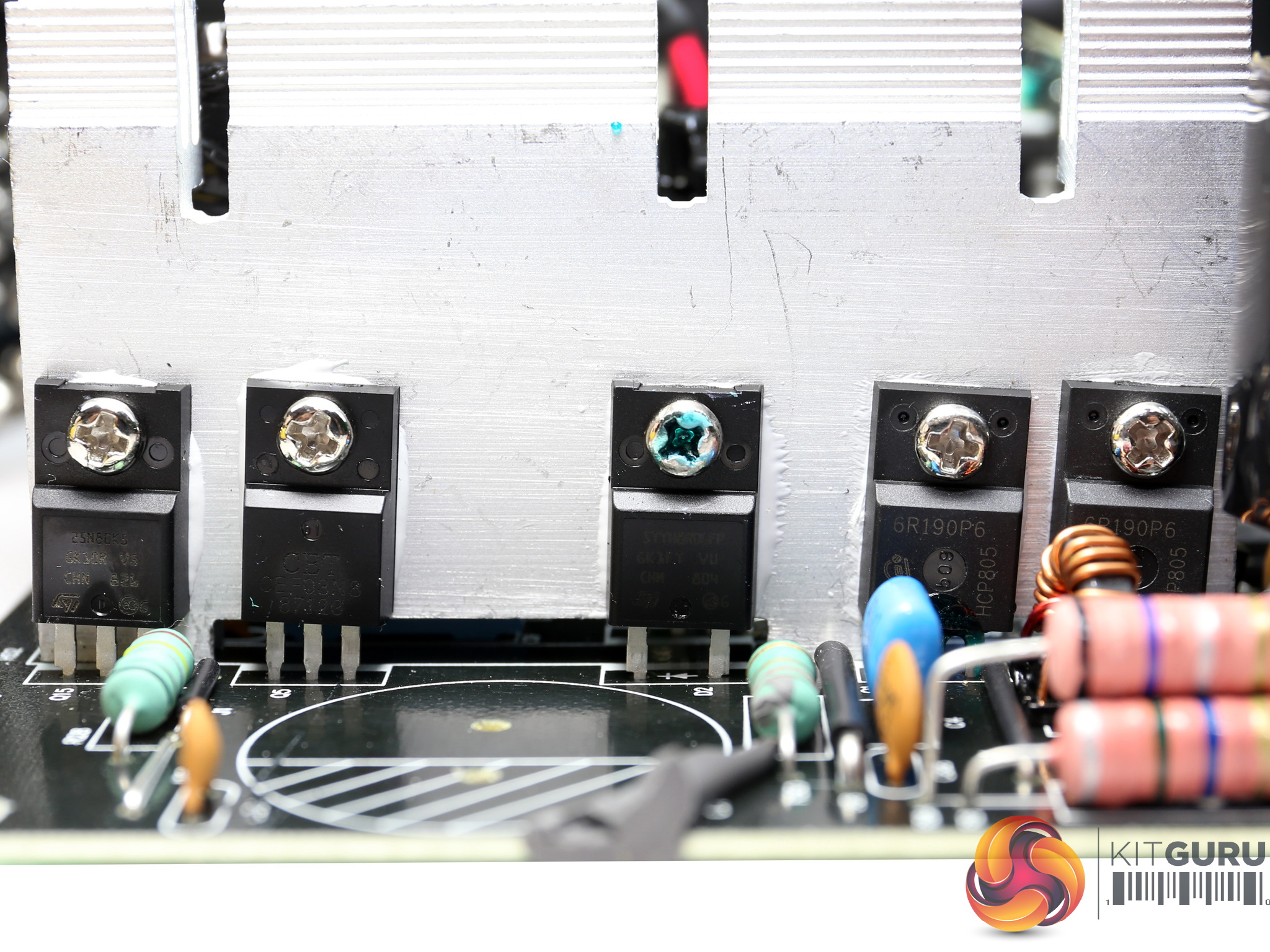
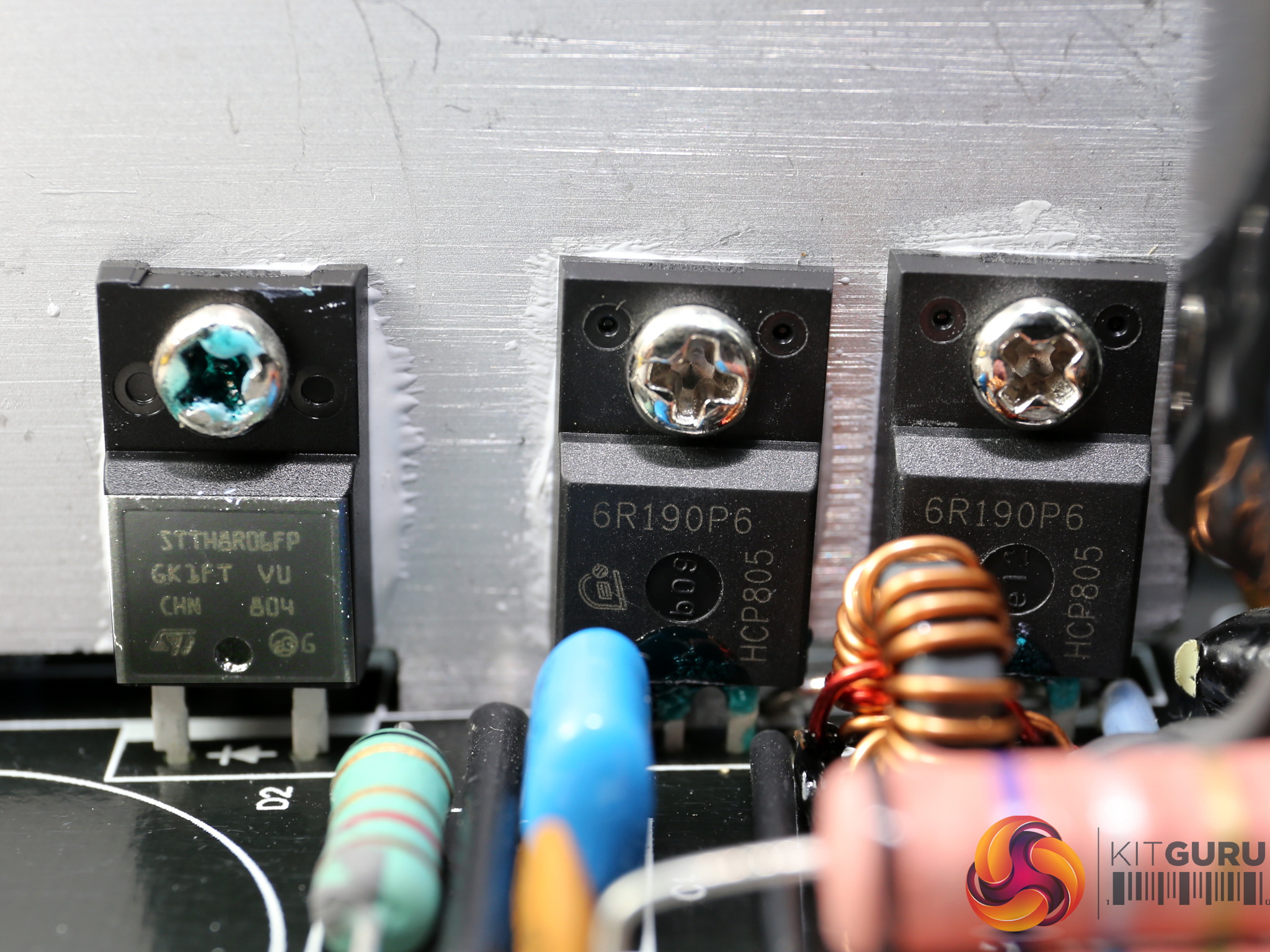
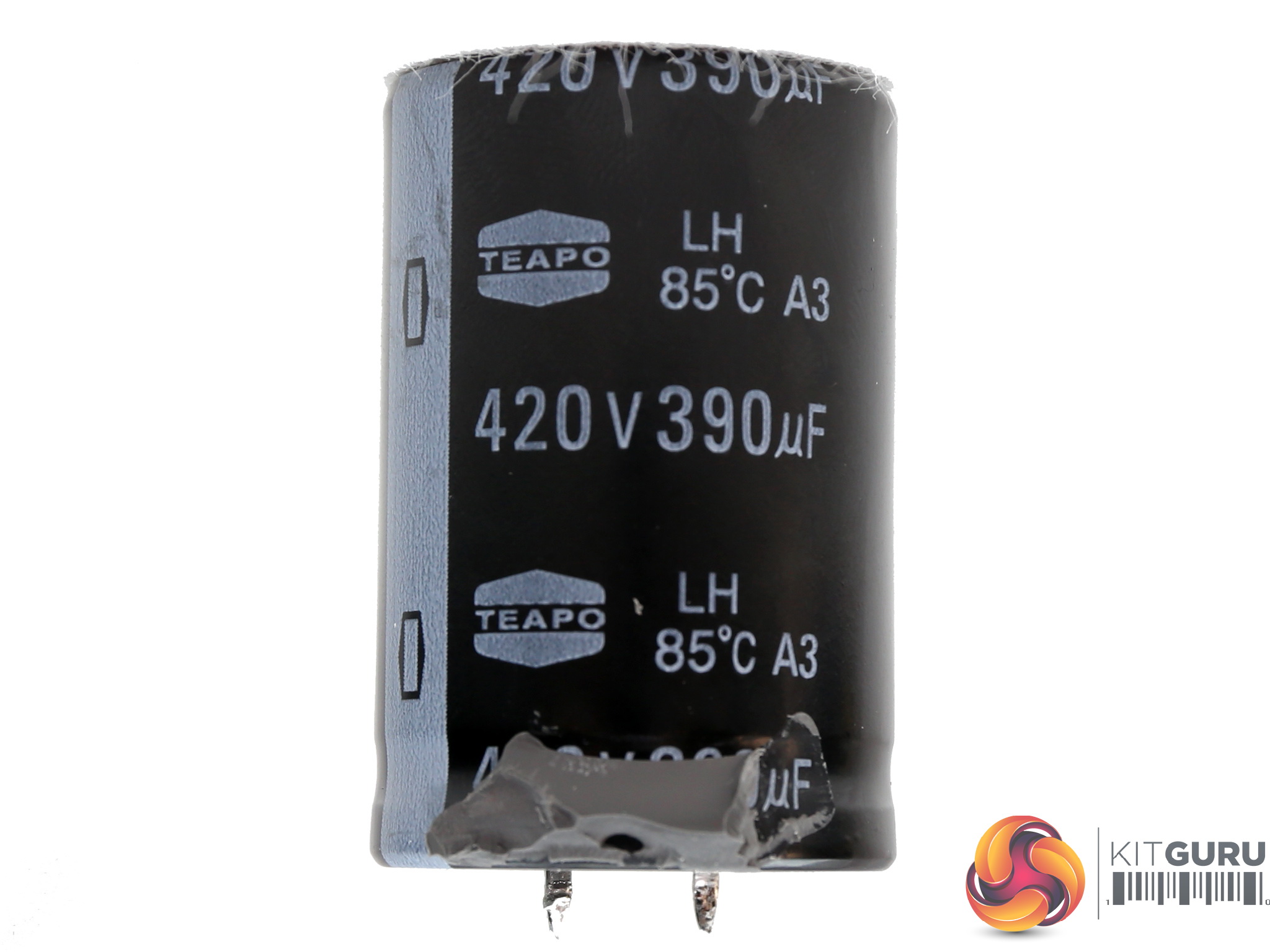
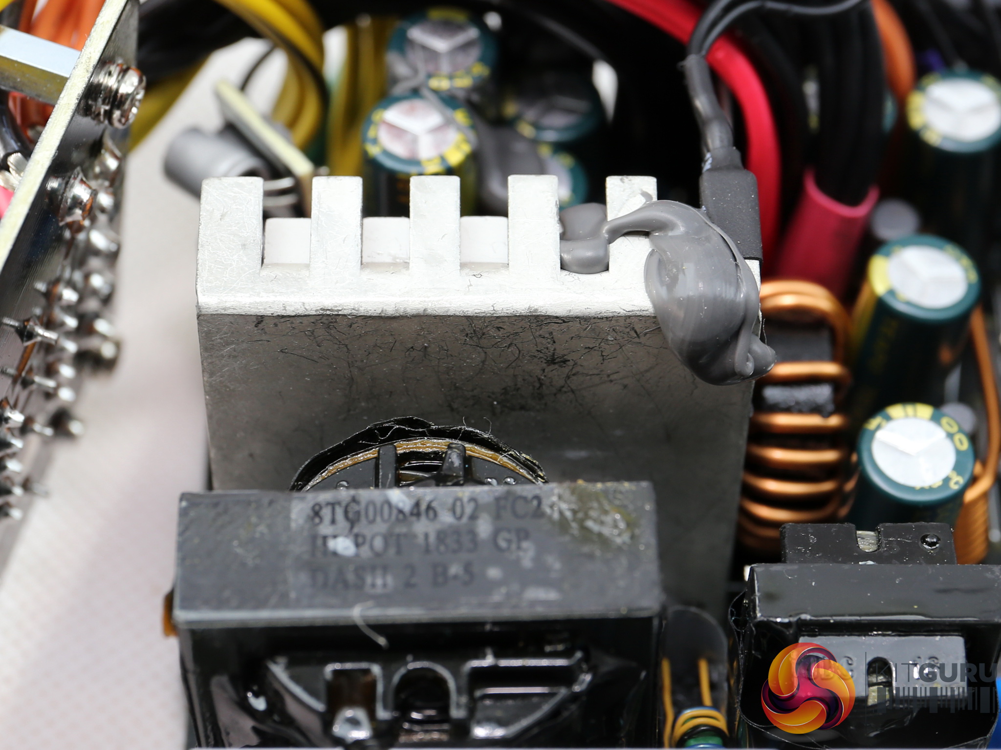
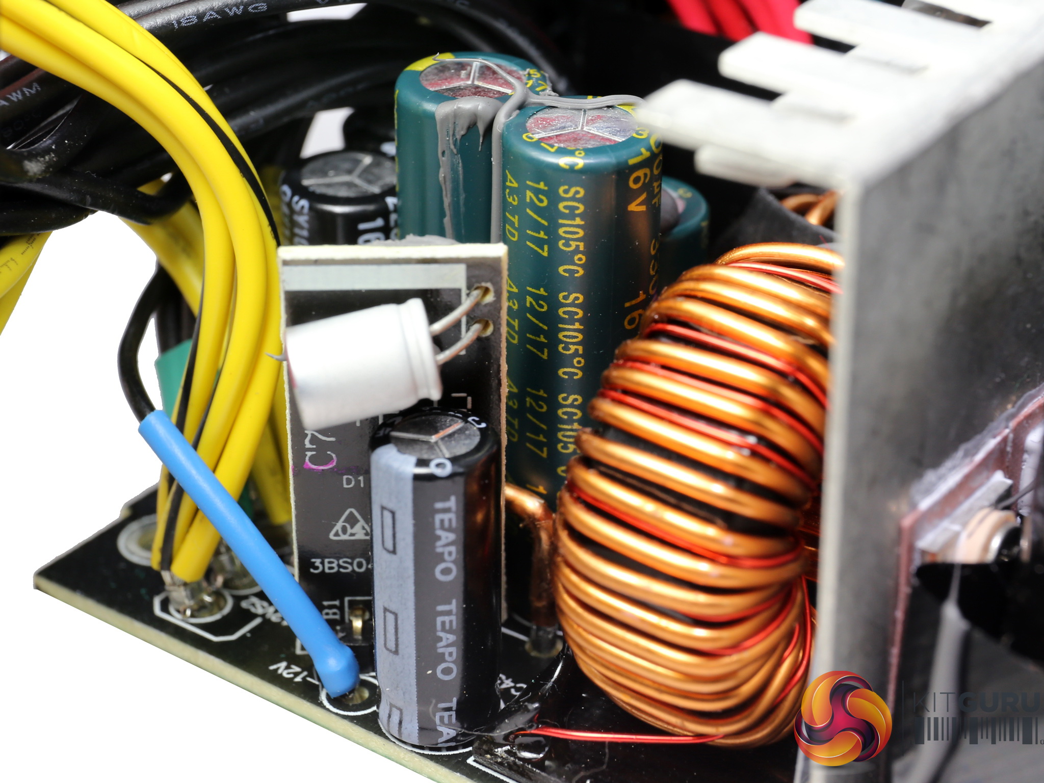
The APFC converter uses two Infineon IPA60R190P6 FETs and a single STMicroelectronics STTH8R06FP boost diode. The bulk cap is provided by Teapo and is only rated at 85°C. A better component should be used in this stage.
Although this cap has low capacity, still thanks to the ACRF topology the hold-up time that it provides is long.
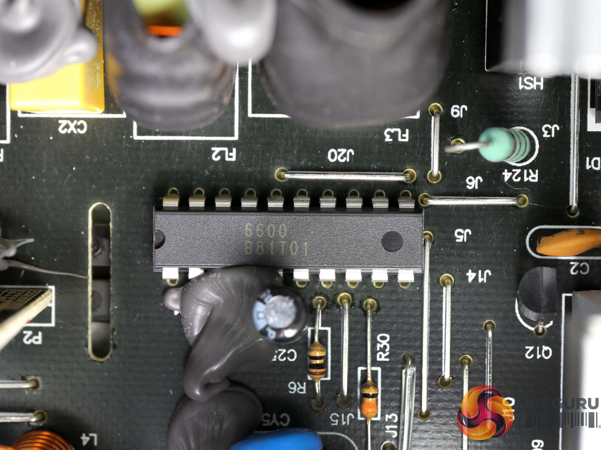
The combo PFC/PWM controller is an FSP6600 IC. There is no information available about it, since it is exclusively made for FSP products.
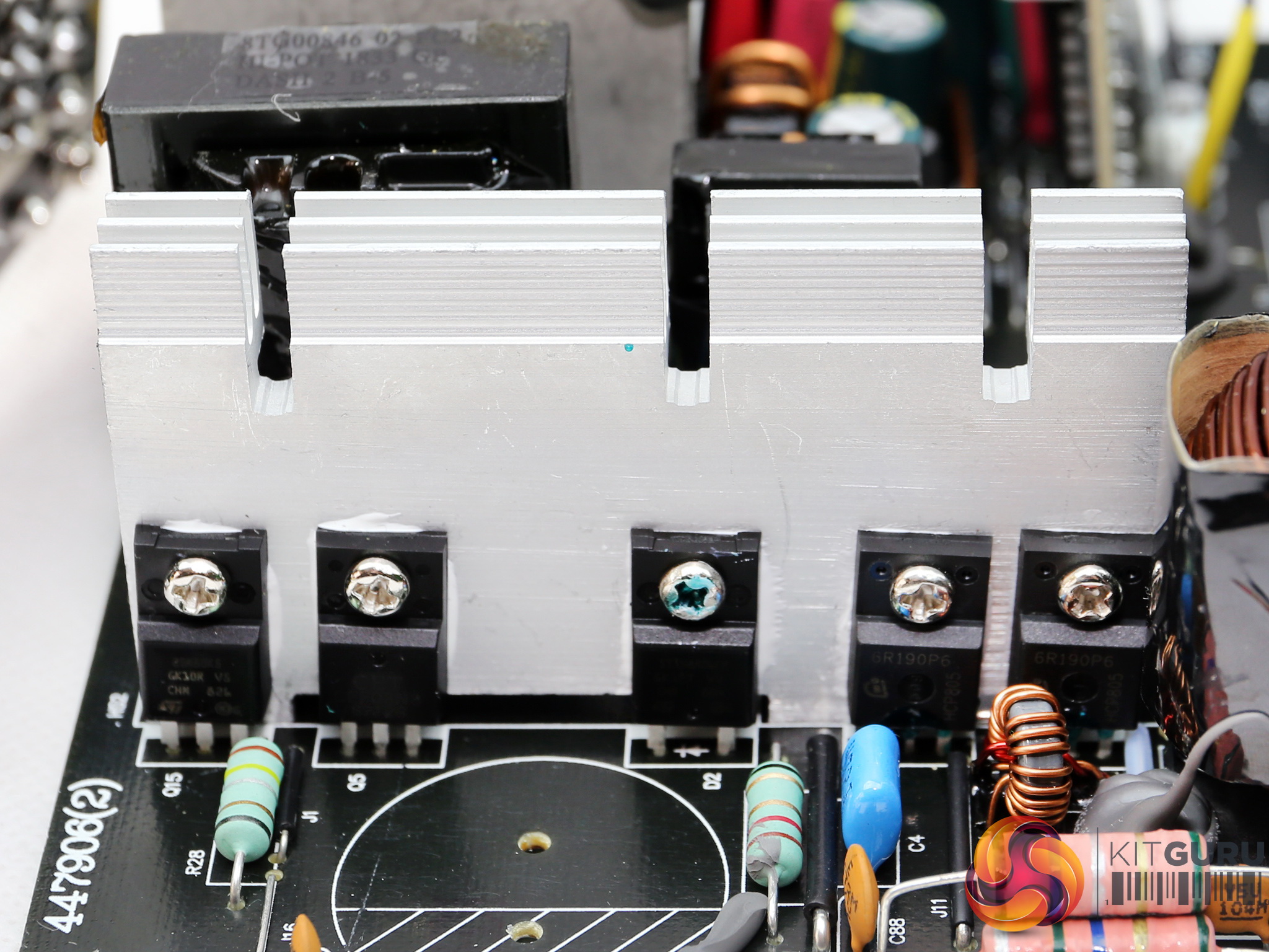
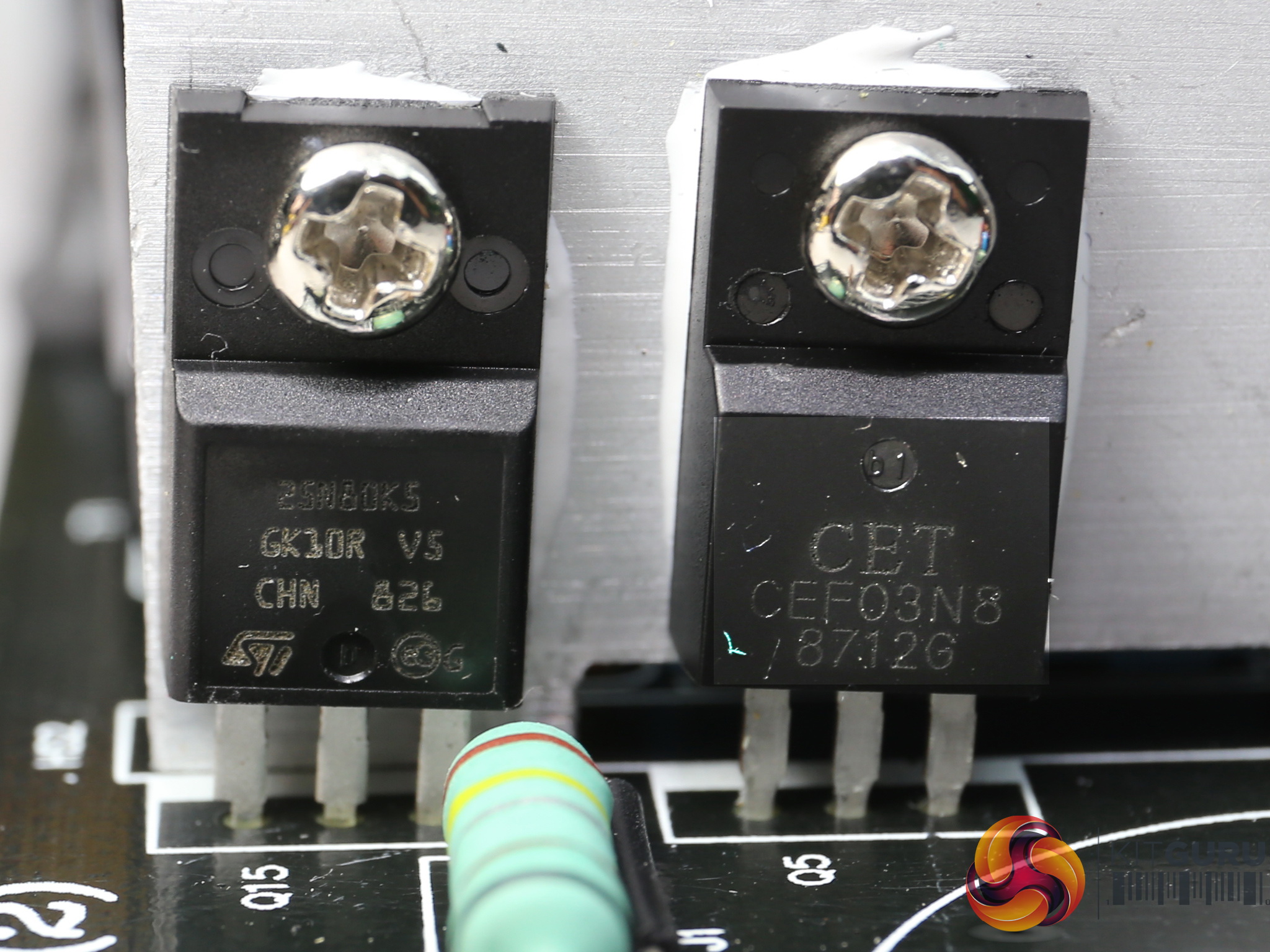
The main switching FET is a STMicroelectronics STF25N80K5 and the reset switch is a CET CEF03N8.
![]()
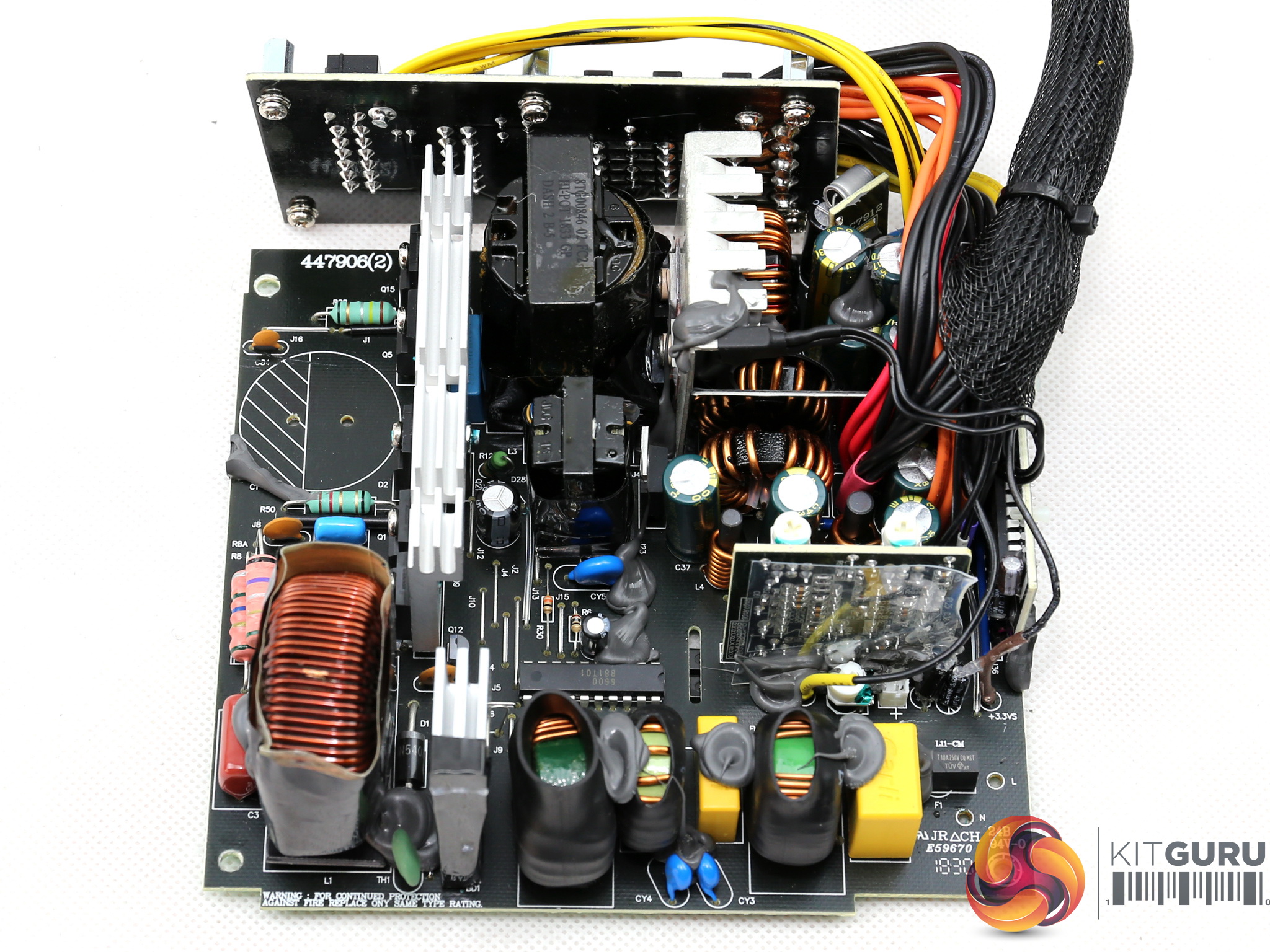
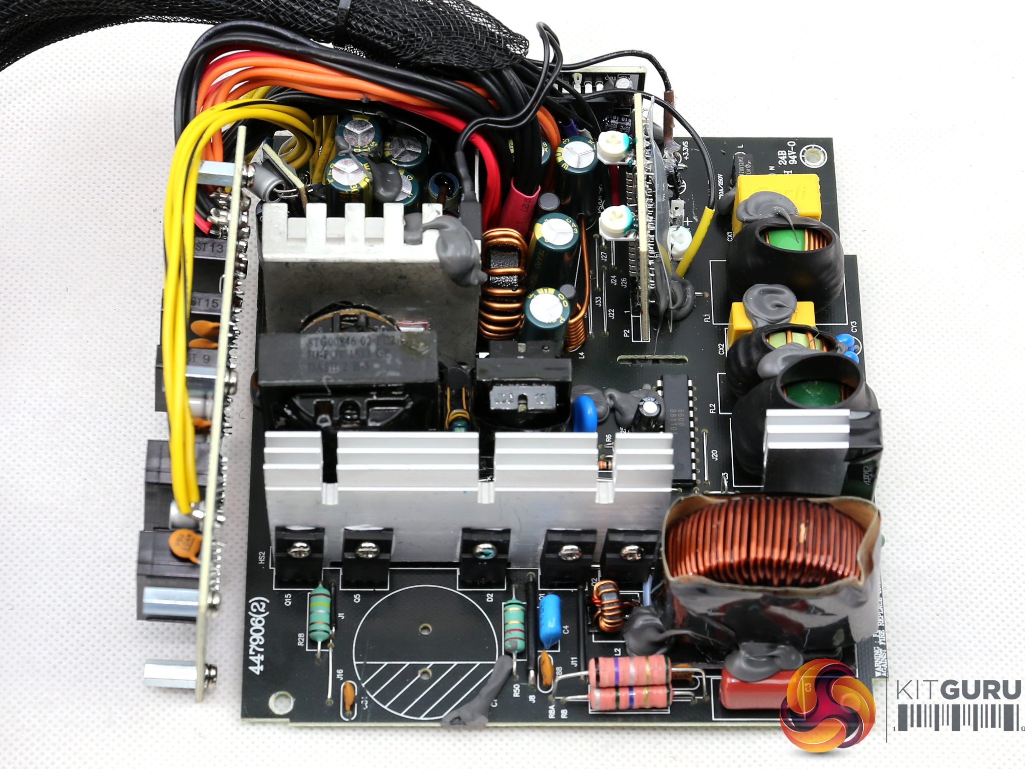
Two FETs regulate the +12V rail, and it is impossible to identify them without removing either their heatsink, or the main transformer. In general this platform is hard to work with.
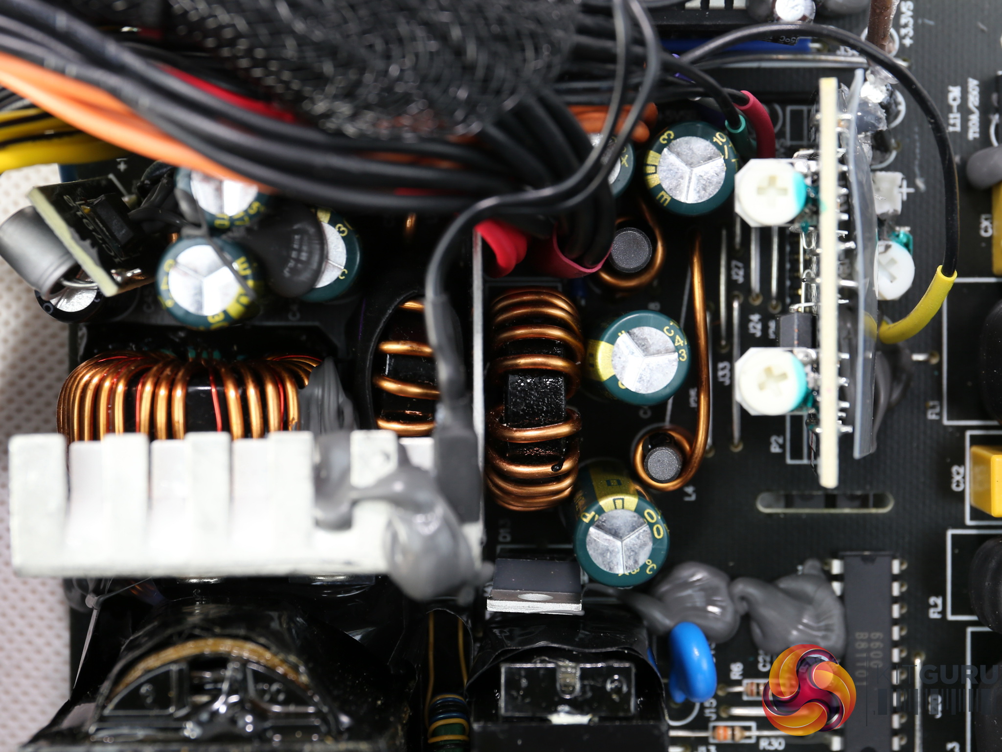
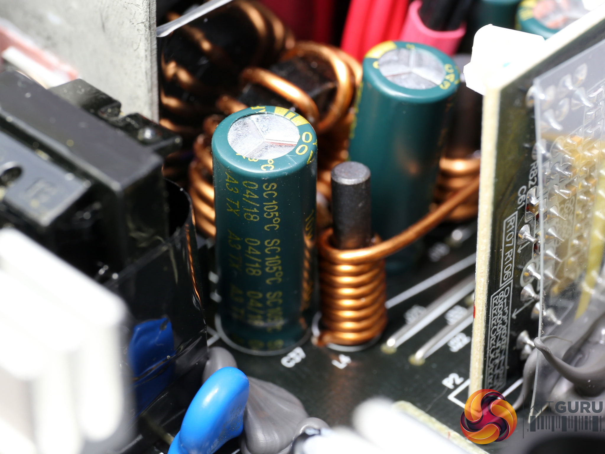
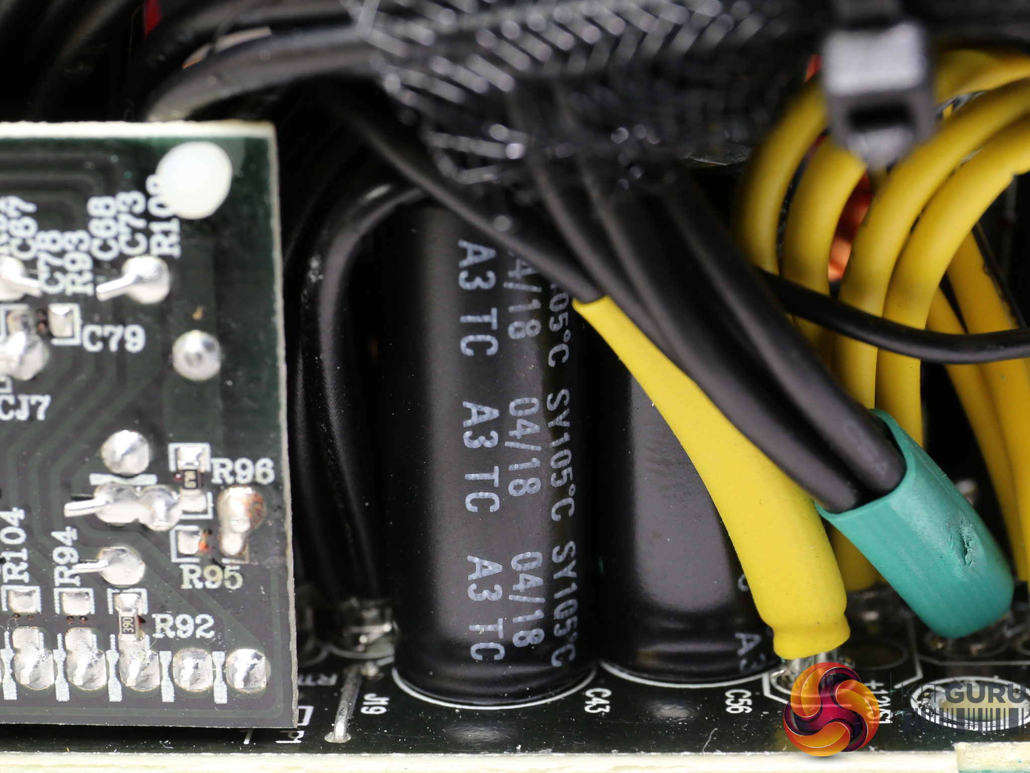
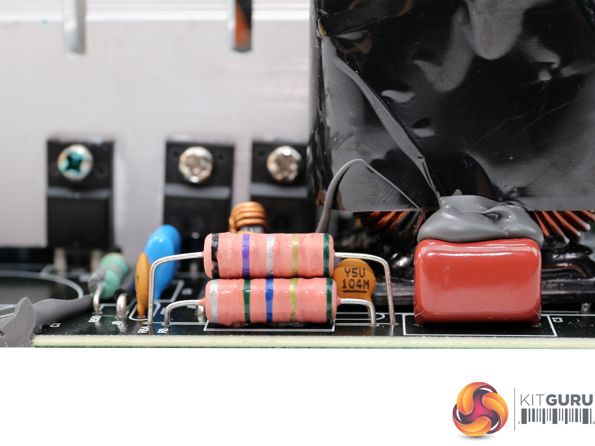
All filtering caps are provided by Teapo with the majority of them belonging to the mainstream SC line. We were expecting to see higher quality parts in a product of this price range.
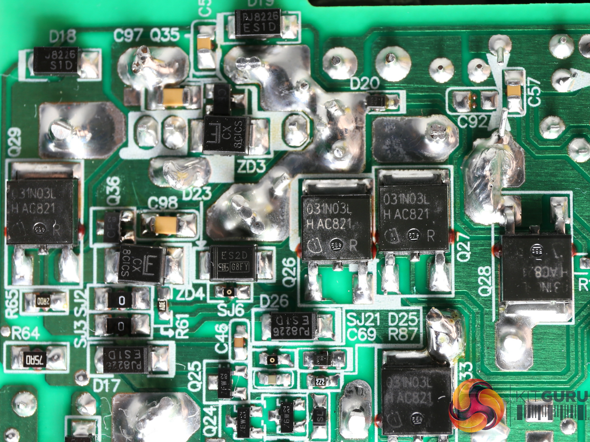
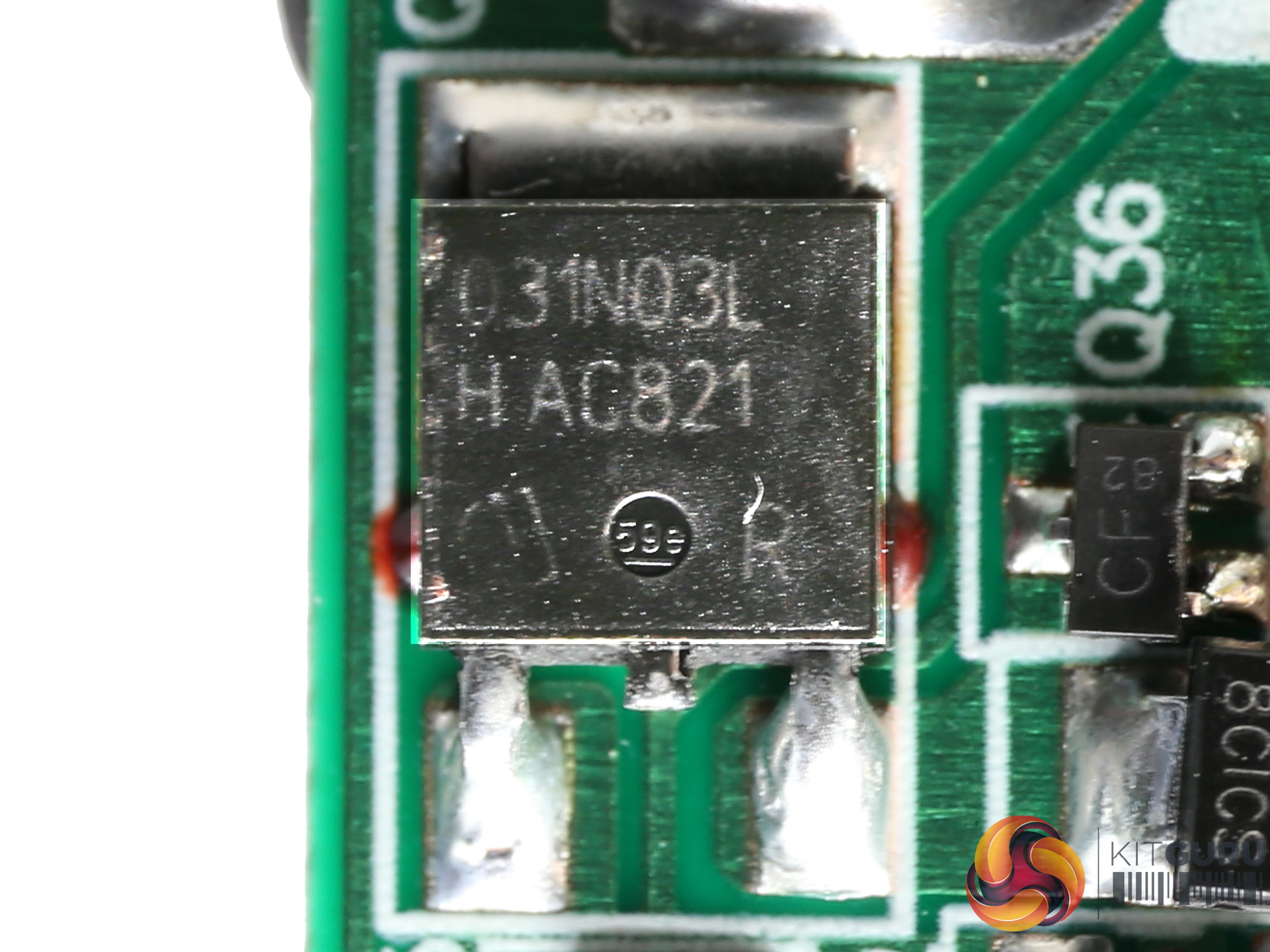
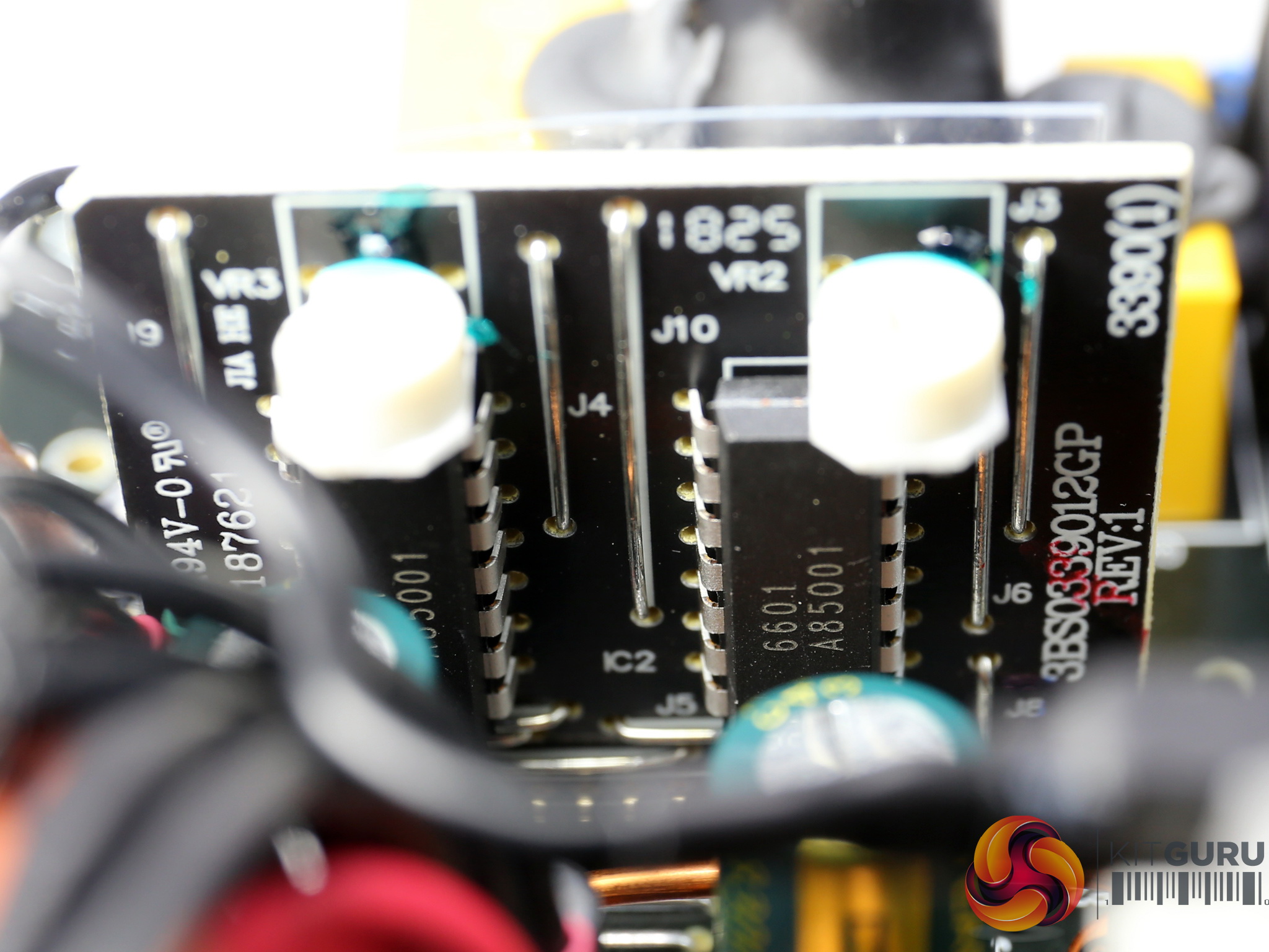
The voltage regulation modules are installed on the solder side of the PCB, instead of a daughter-board. In total four Infineon IPD031N03L G are used in this circuit, while the PWM controllers are two FSP6601 ICs.
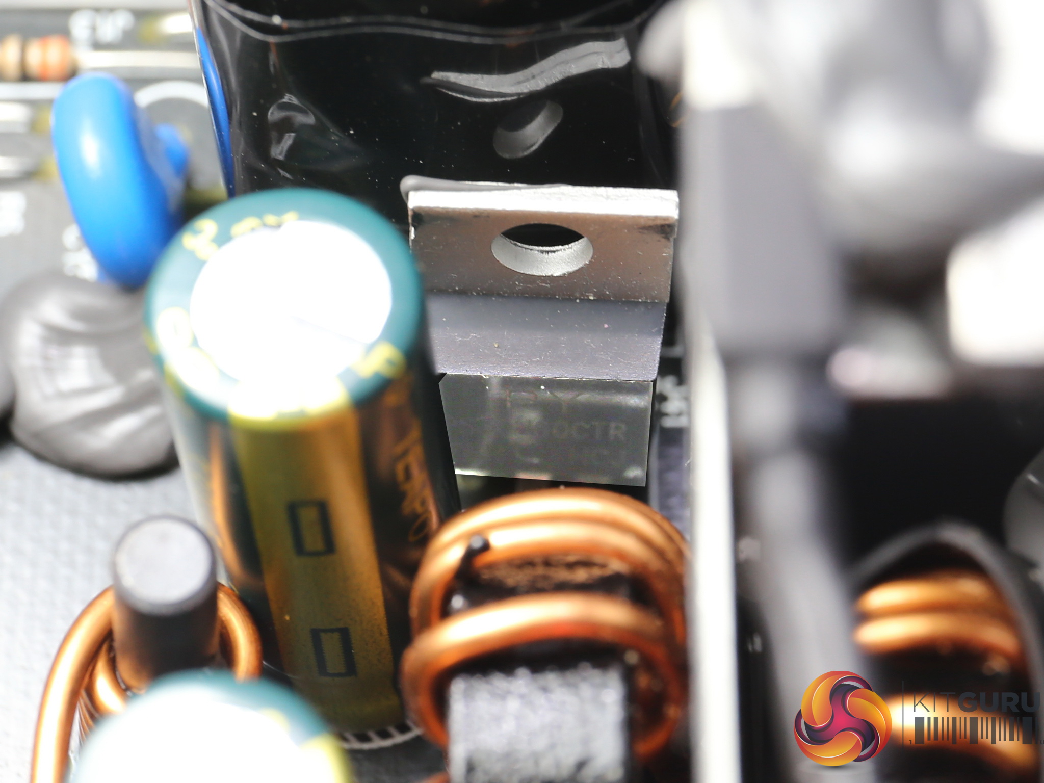
The 5VSB rail is rectified by a CET CEF02N7G and a PS30U60CTR SBR.
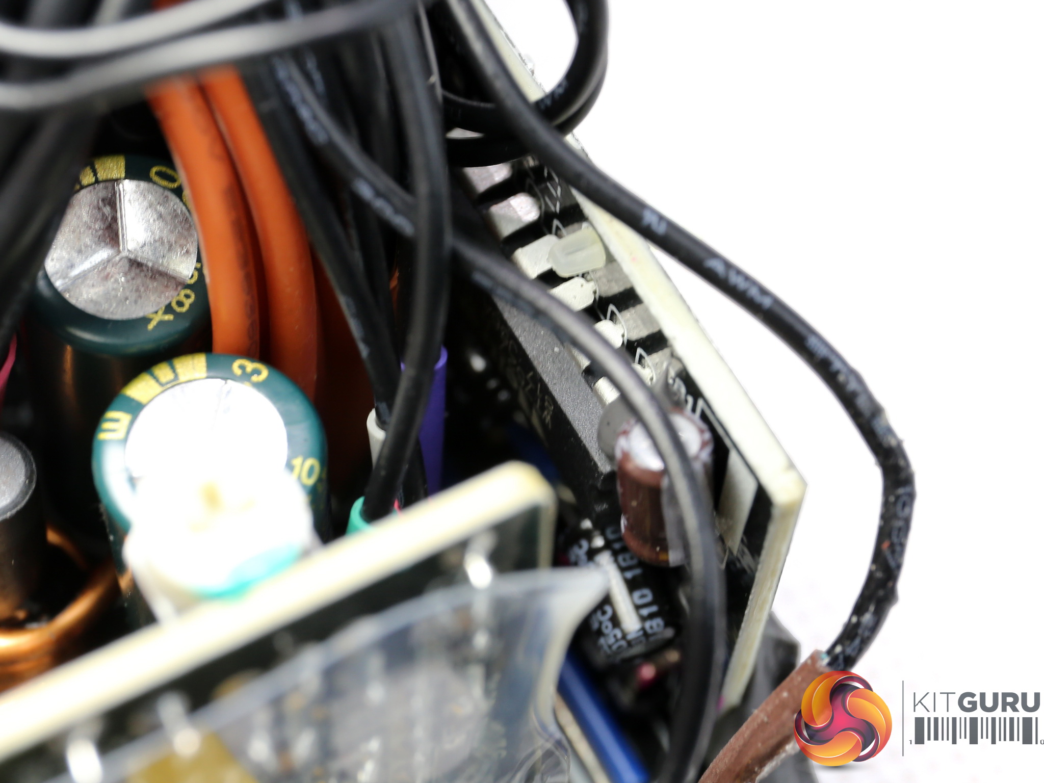
The supervisor IC is a Weltrend WT7527 which among others has two +12V OCP channels.
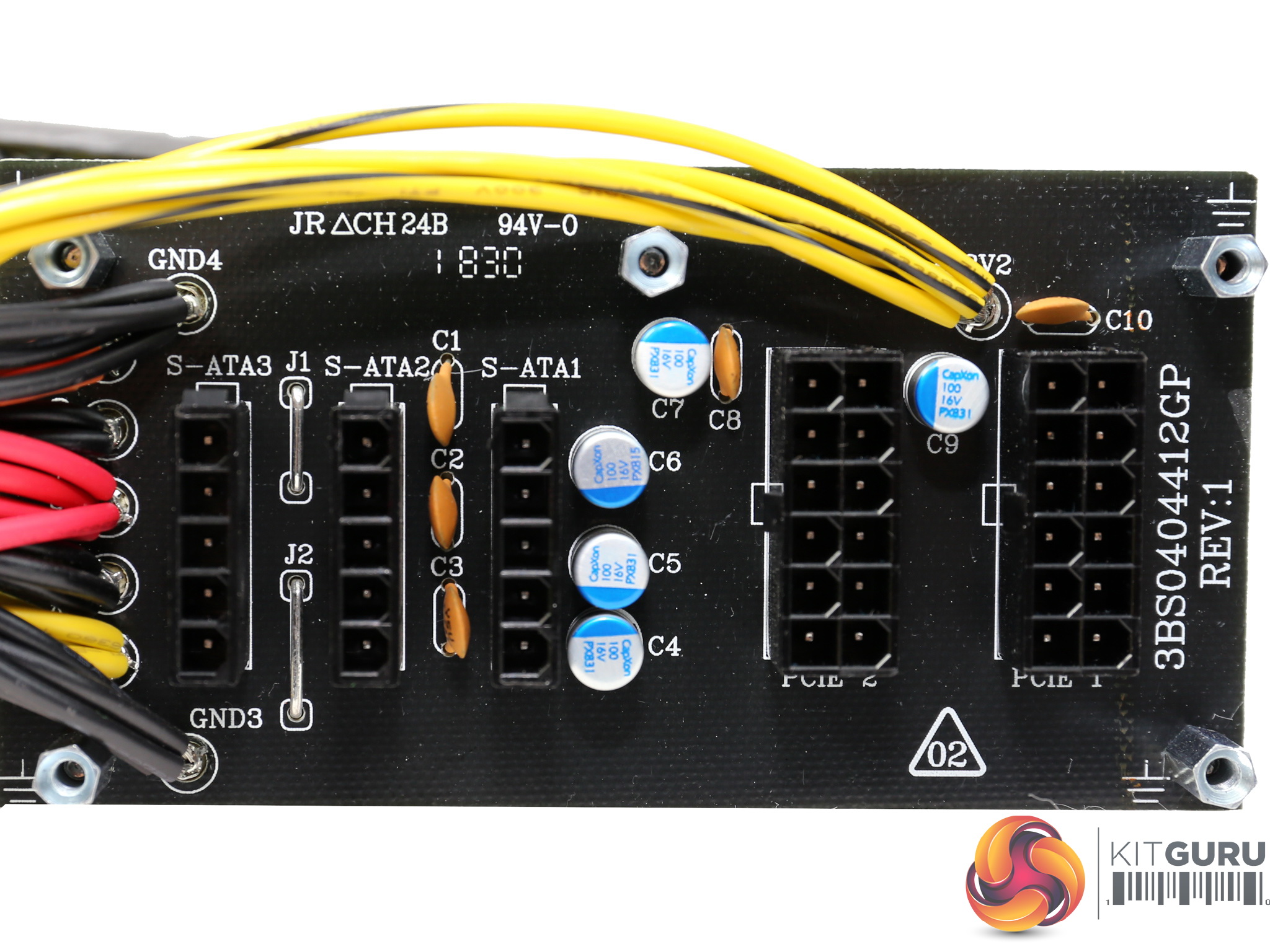
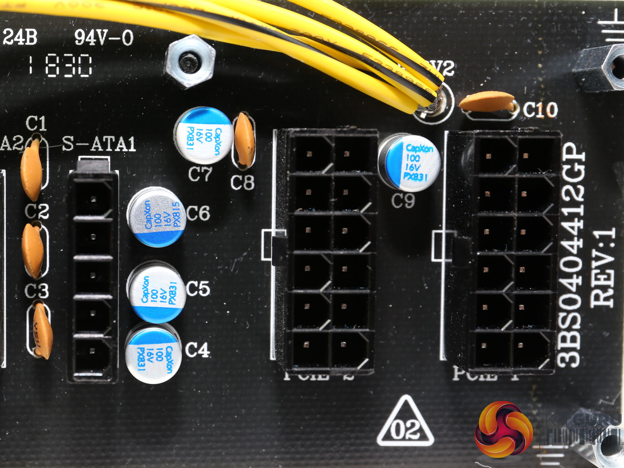
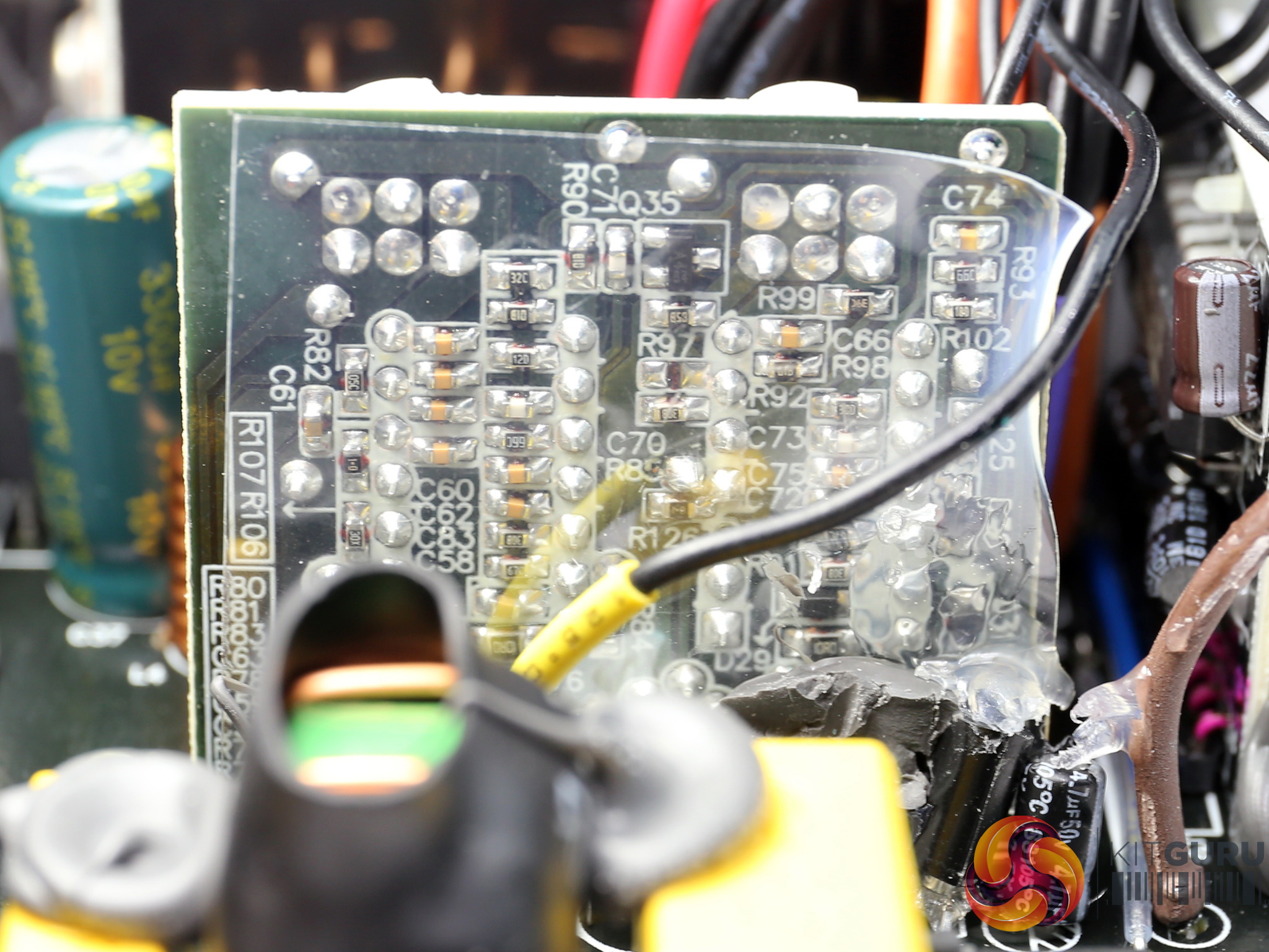
At the front of the modular board several polymer CapXons are installed, along with five ceramic disc caps which are used for high frequency ripple suppression.
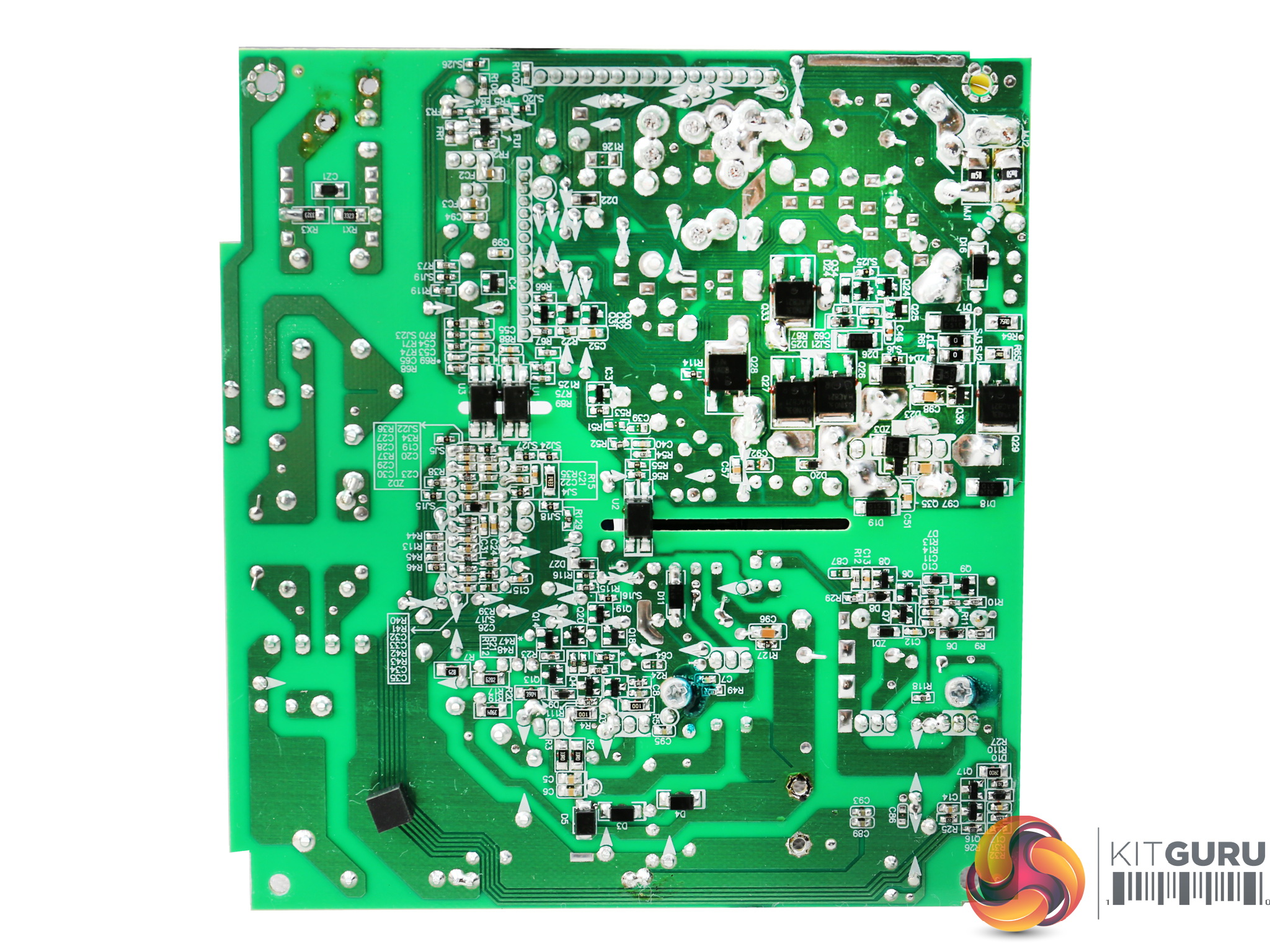
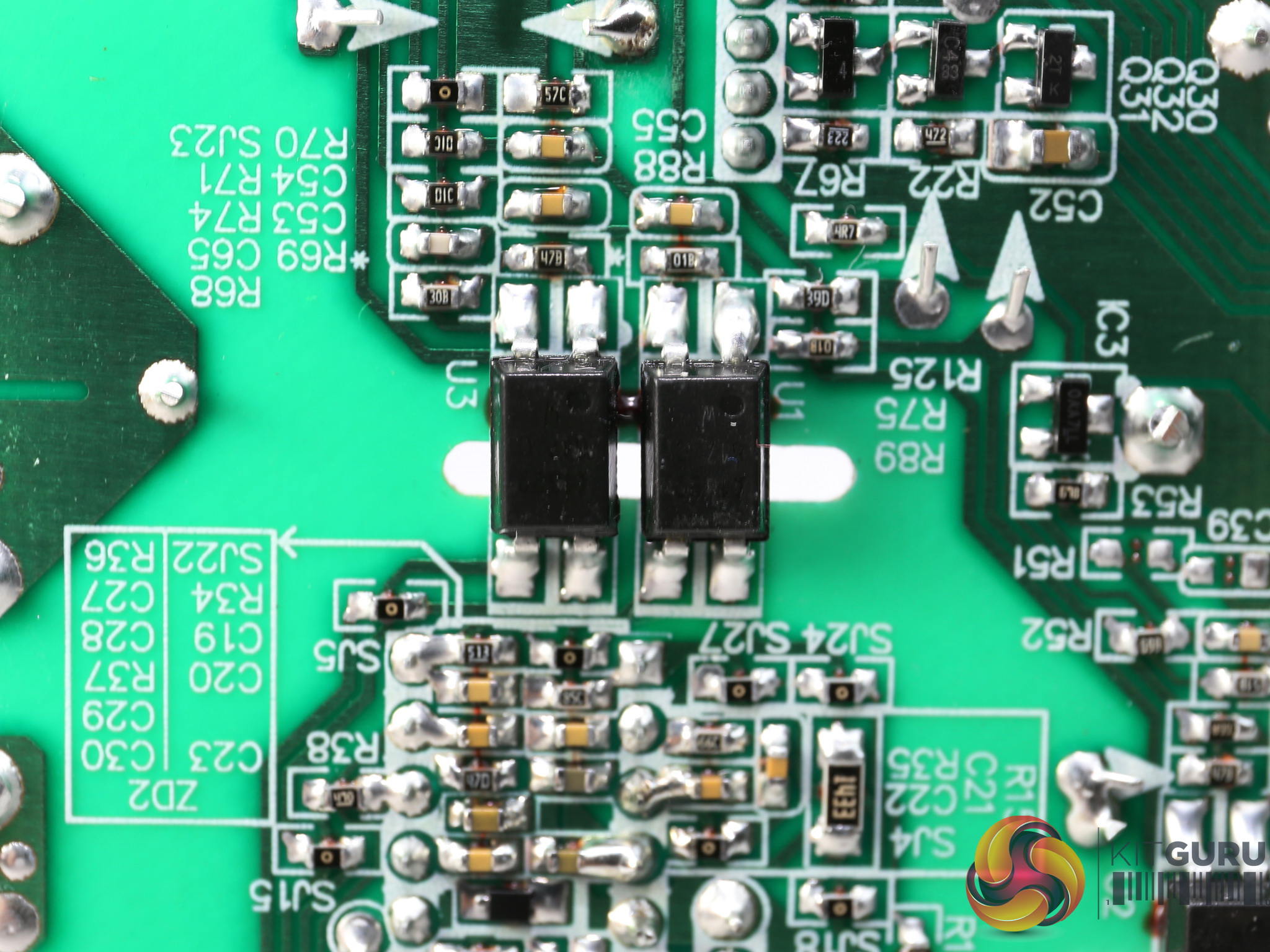
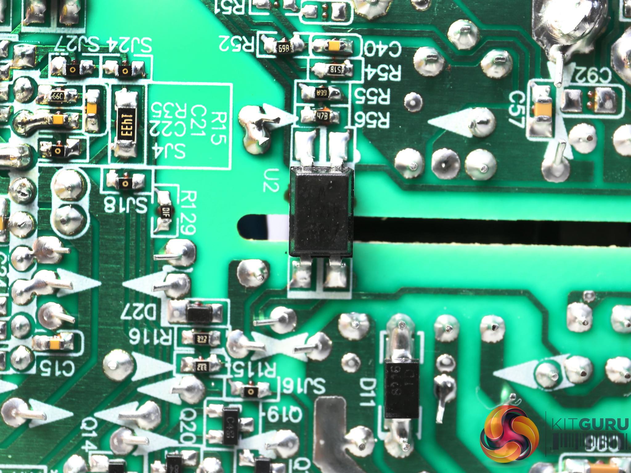
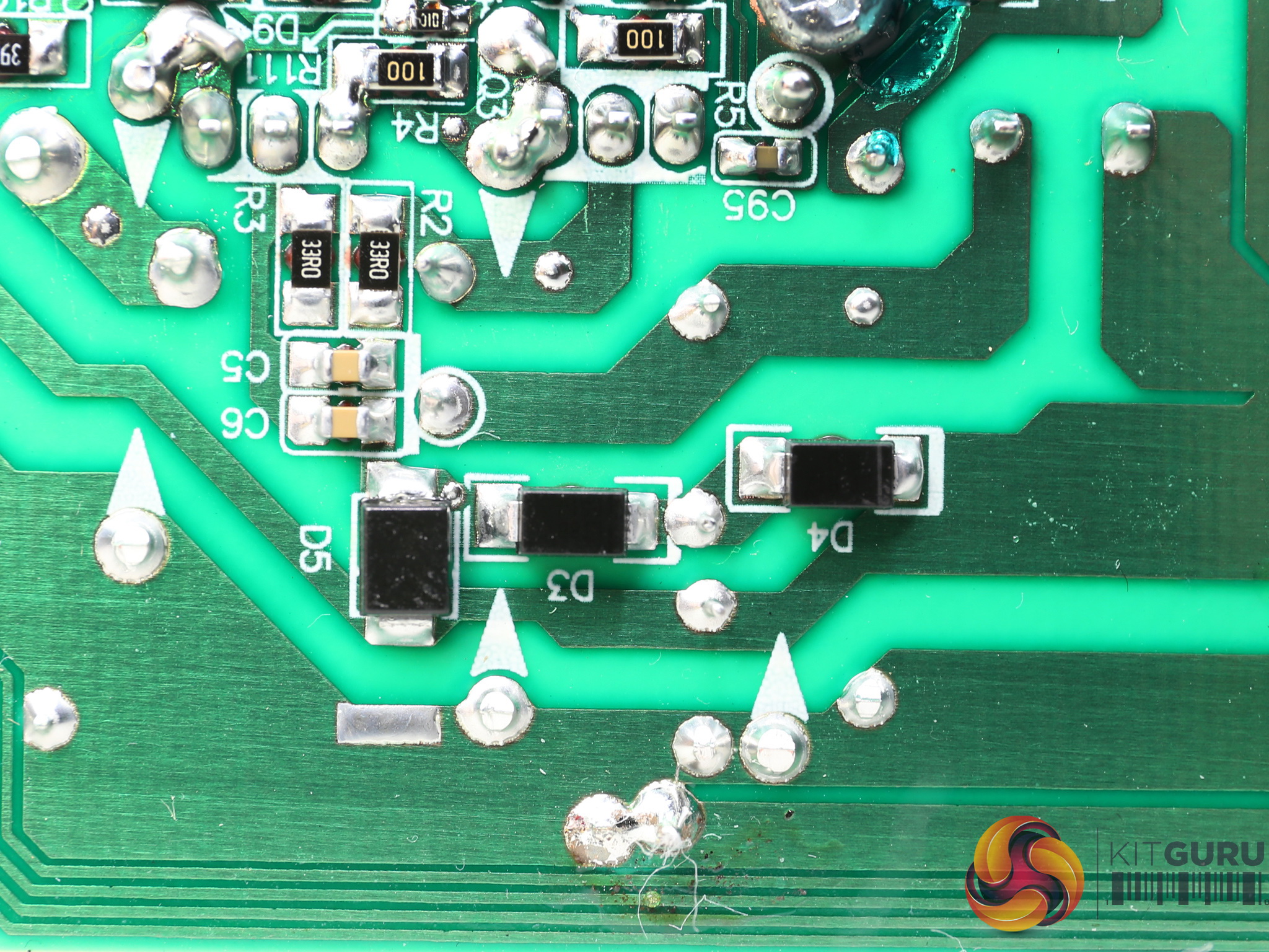
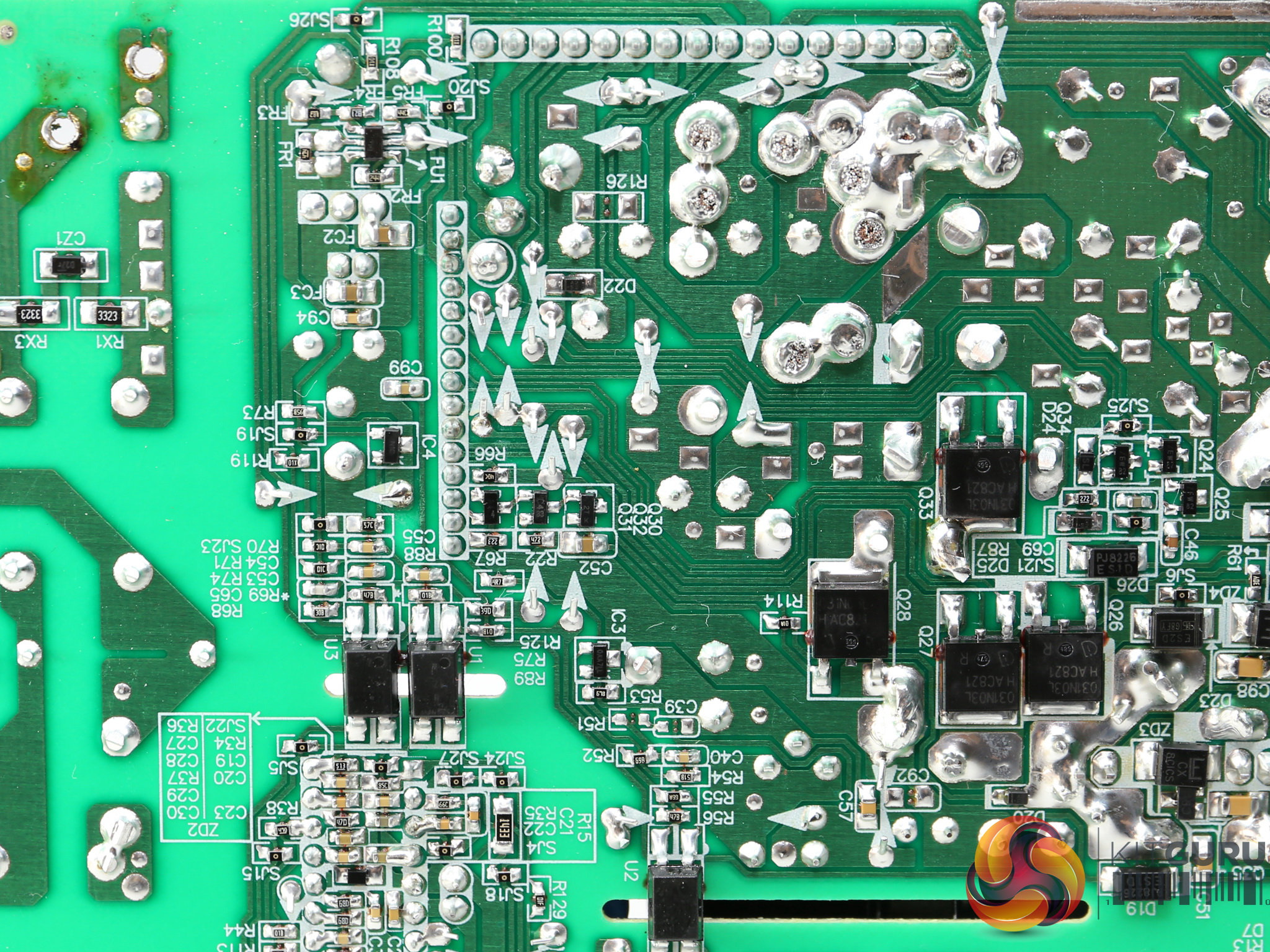
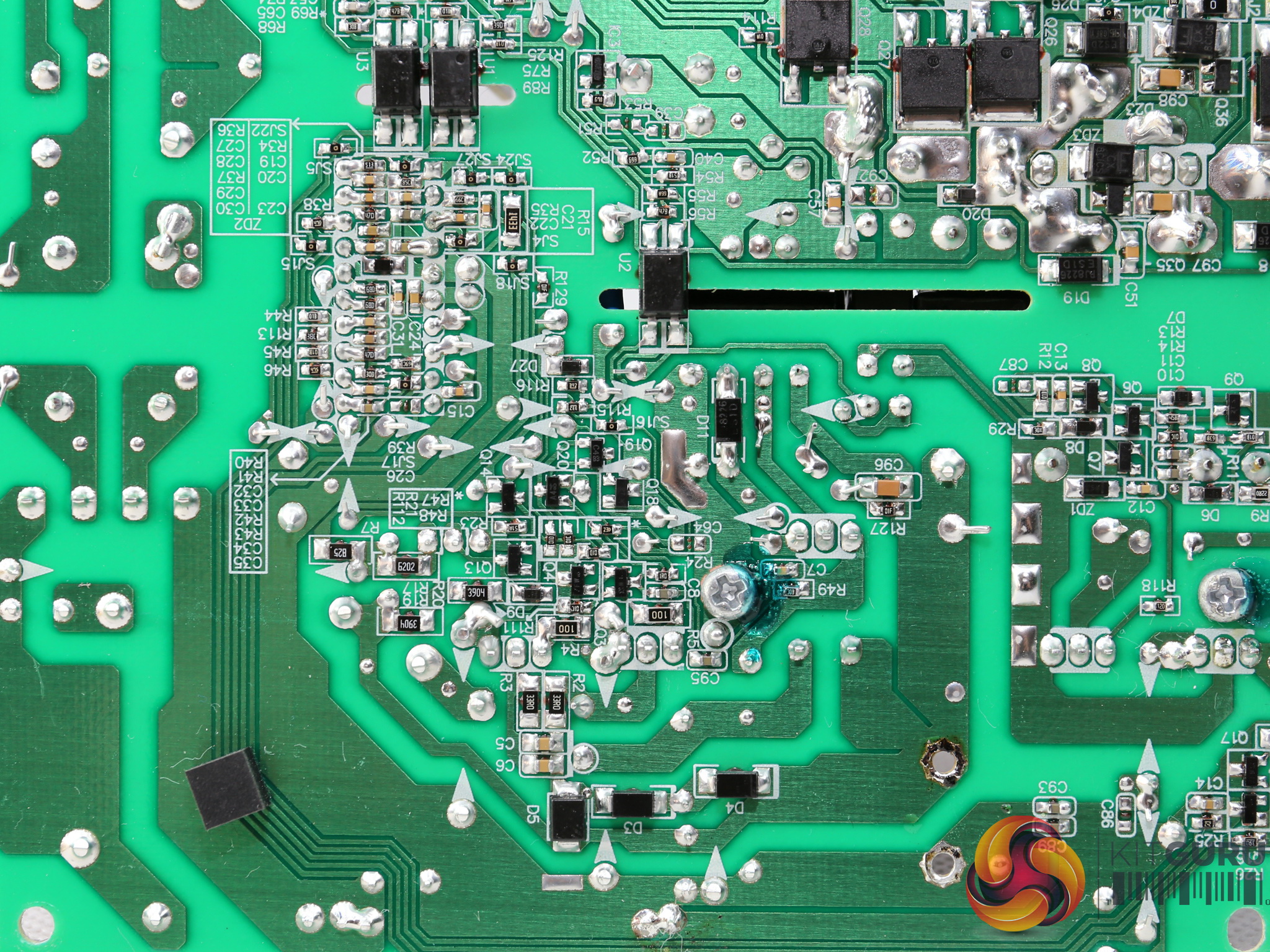
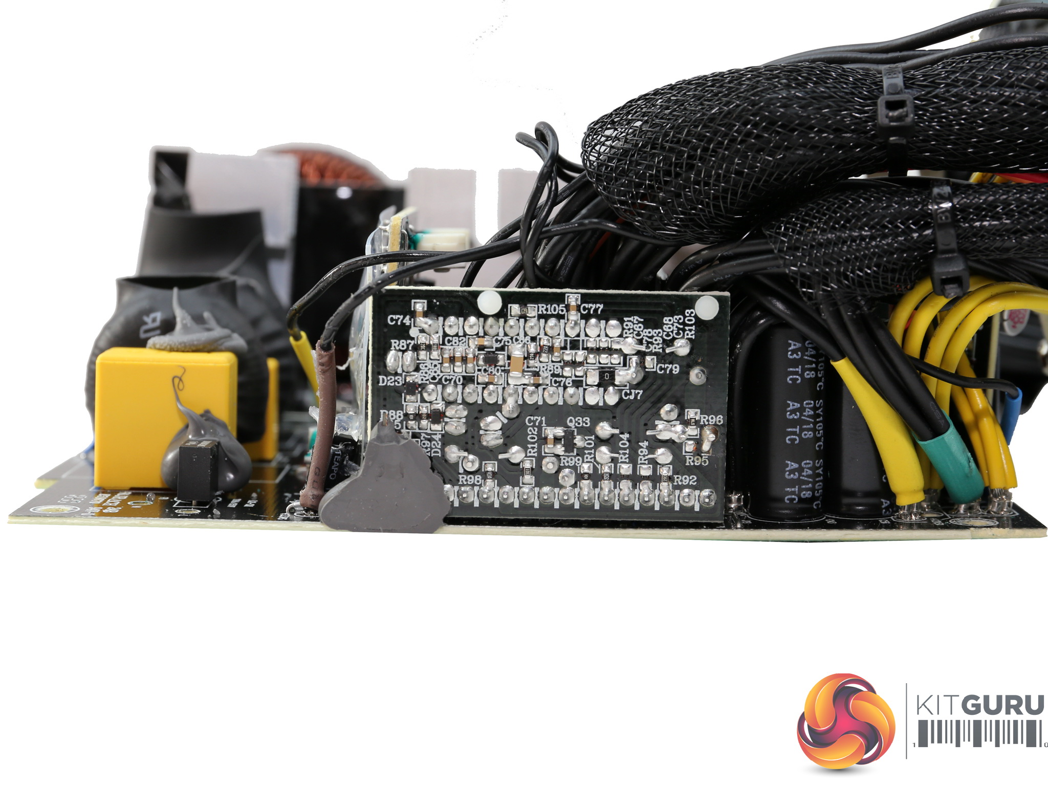
The soldering quality is not the best we have seen from FSP. Moreover, some component leads are quite long. On the positive side, the PCB is clean, without any notable traces of flux residue.
The couple of burn marks are our fault, since we had to desolder some parts and because of the lead-free solder, high temperatures needed to be applied.
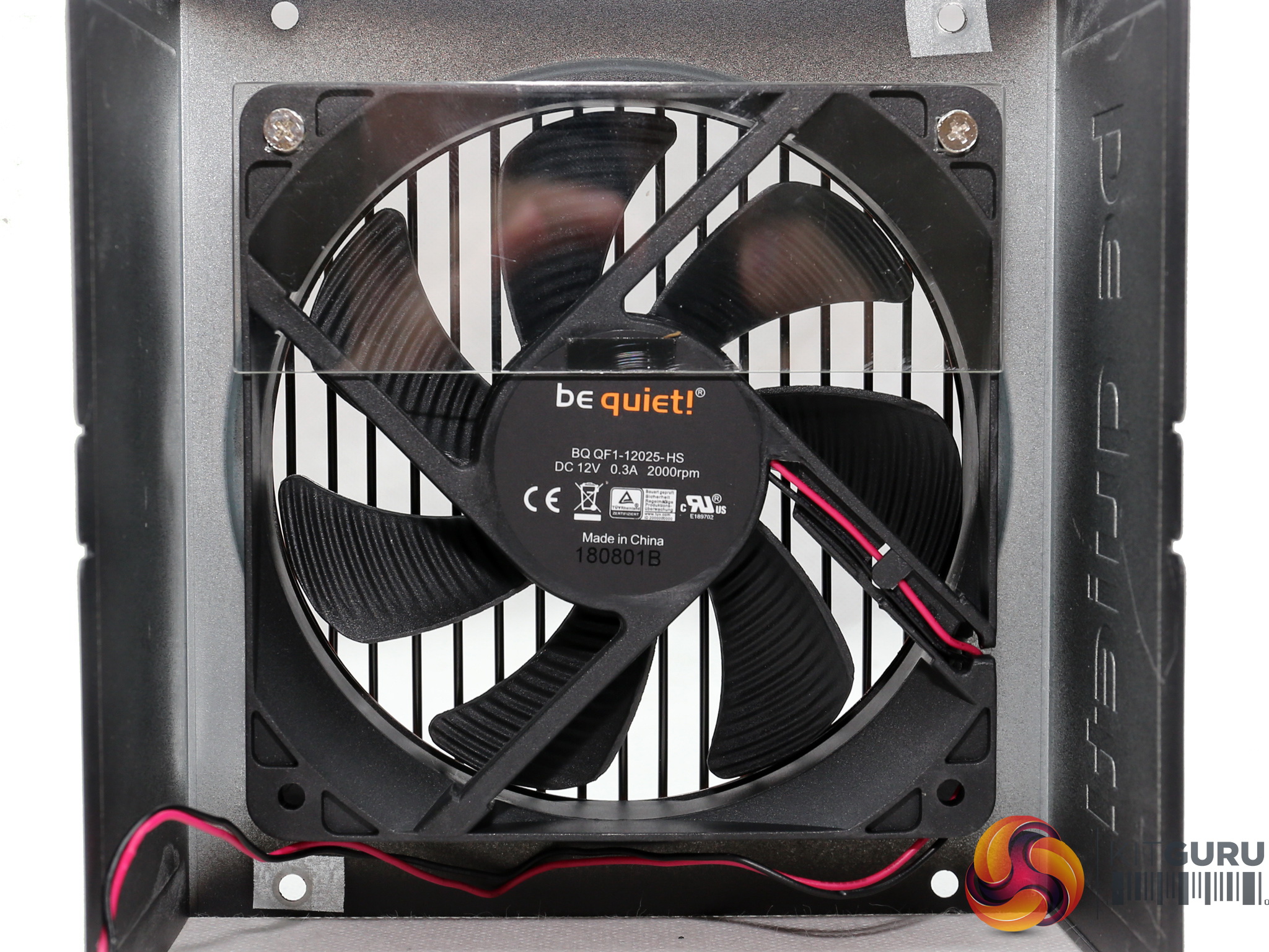
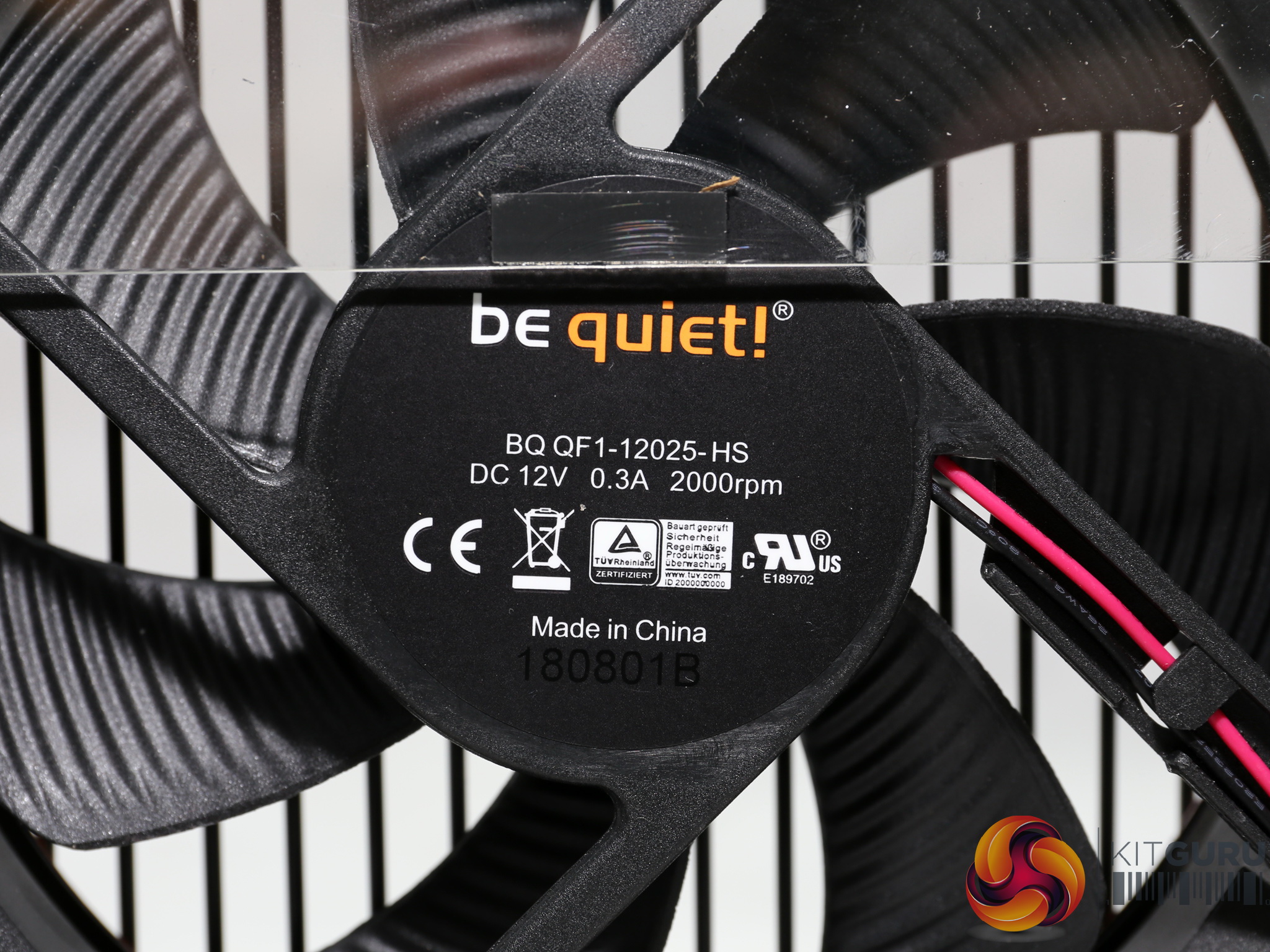
The cooling fan (BQ QF1-12025-HS) uses a rifle bearing and measures 120mm in diameter. Thanks to the relaxed fan profile, the noise output remains low and on top of that, we didn't notice any high-pitched sounds (aka coil whine) coming out from this platform.
To learn more about our PSU tests and methodology, please check out How We Test Power Supply Units.
Primary Rails And 5VSB Load Regulation
Load Regulation testing is detailed here.
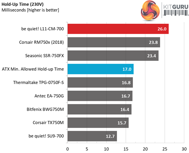
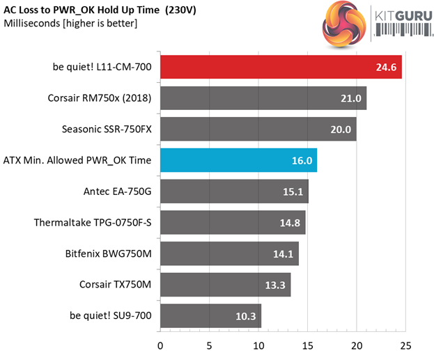
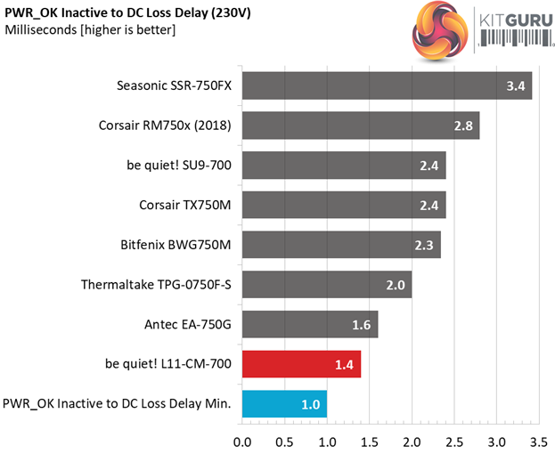
Hold-Up Time
Our hold-up time tests are described in detail here.
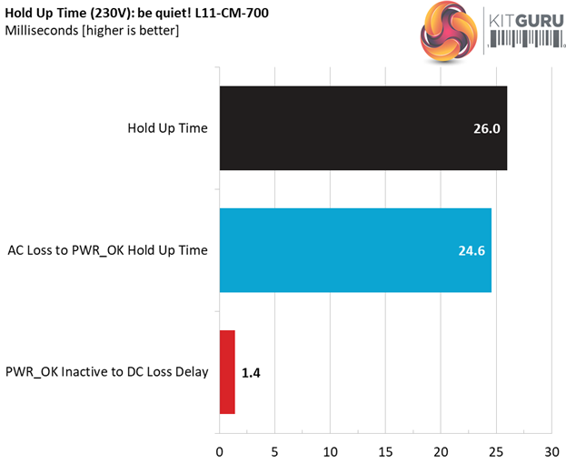
The oscilloscope screenshots that we took during the hold-up time measurements:
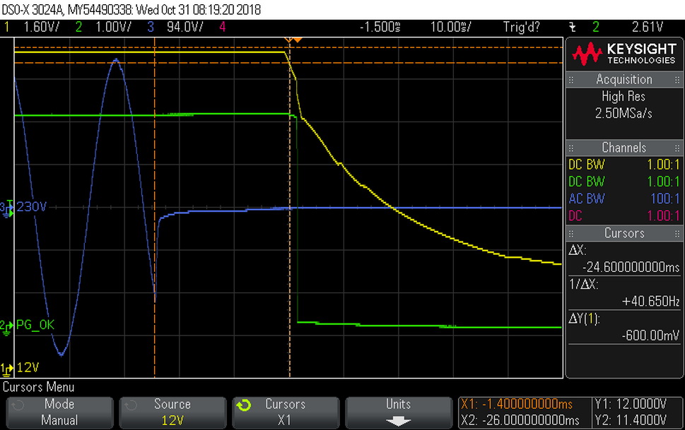
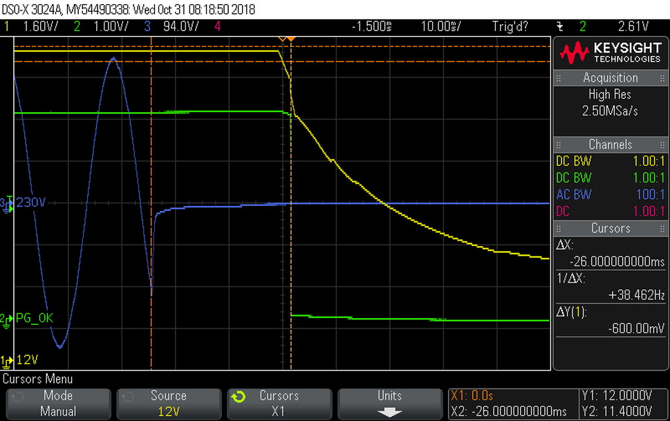
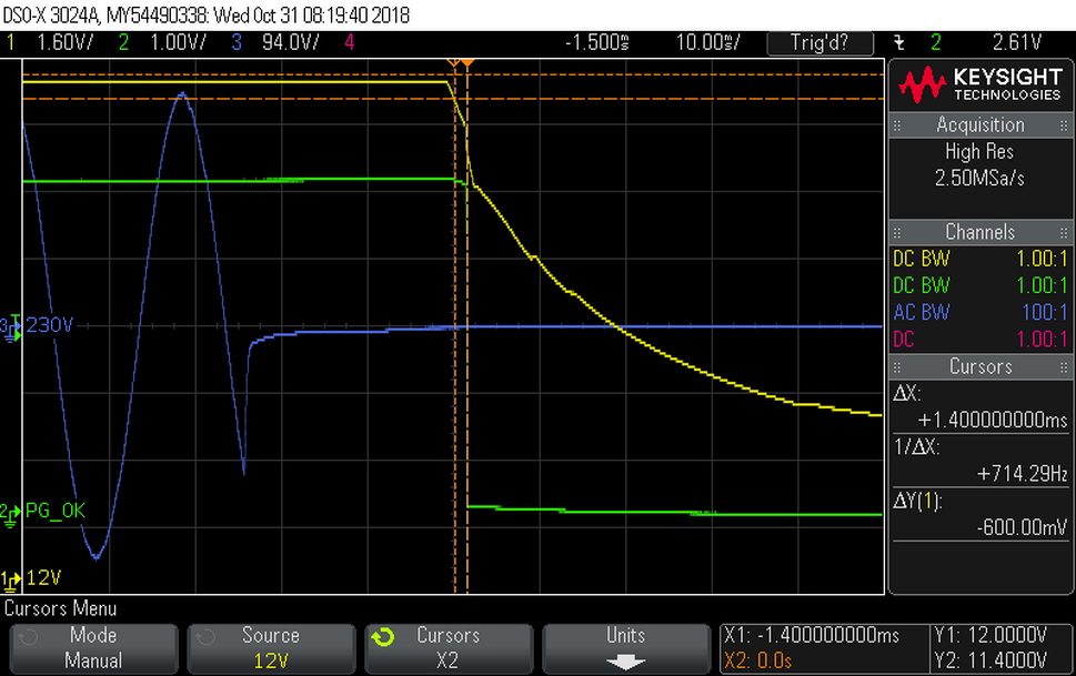
The hold-up time is long, something that we expected because of the ACRF topology, and the power ok signal is accurate.
Inrush Current
For details on our inrush current testing, please click here.
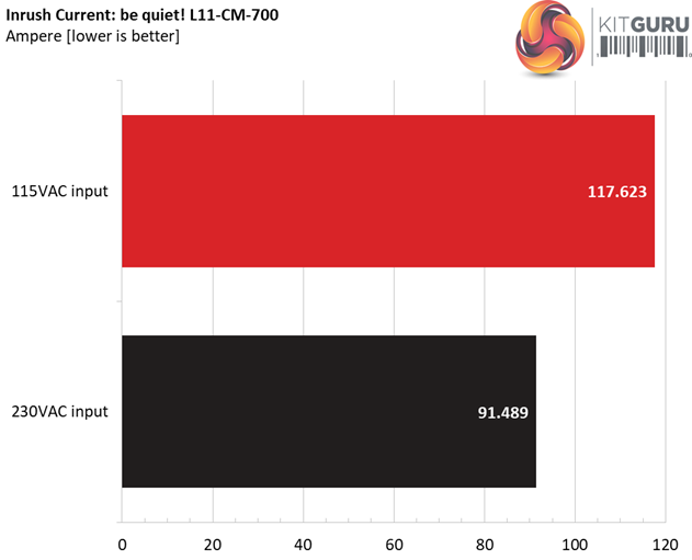
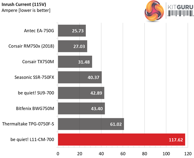
We measure very high inrush currents, with both voltage inputs. The NTC thermistor, responsible for lowering those currents, is small and on top of that it is not supported by a bypass relay, so it gets hot soon and its resistance drops.
Load Regulation And Efficiency Measurements
The first set of tests reveals the stability of the voltage rails and the L11-CM-700’s efficiency. The applied load equals (approximately) 10 to 110 percent of the power supplies maximum load in increments of 10 percentage points.
We conducted two additional tests.
During the first, we stressed the two minor rails (5V and 3.3V) with a high load, while the load at +12V was only 0.1A. This test reveals whether a power supply is compatible with Intel’s C6/C7 sleep states or not. In the second test, we determined the maximum load the +12V rail could handle with minimal load on the minor rails.
| Test # | 12V | 5V | 3.3V | 5VSB | DC/AC (Watts) | Efficiency | Fan Speed (RPM) | PSU Noise (dB[A]) | Temps (In/Out) | PF/AC Volts |
| 1 | 3.971A | 1.990A | 1.948A | 0.985A | 69.651 | 86.337% | 685 | 12.5 | 40.04°C | 0.915 |
| 12.101V | 5.026V | 3.386V | 5.077V | 80.673 | 44.95°C | 115.05V | ||||
| 2 | 9.002A | 2.991A | 2.933A | 1.185A | 139.723 | 90.135% | 687 | 12.1 | 40.45°C | 0.948 |
| 12.088V | 5.017V | 3.375V | 5.064V | 155.015 | 45.72°C | 115.05V | ||||
| 3 | 14.378A | 3.495A | 3.415A | 1.386A | 209.635 | 91.060% | 687 | 12.1 | 41.26°C | 0.968 |
| 12.076V | 5.009V | 3.367V | 5.052V | 230.217 | 46.74°C | 115.05V | ||||
| 4 | 19.764A | 4.003A | 3.932A | 1.588A | 279.657 | 91.198% | 689 | 11.2 | 41.88°C | 0.979 |
| 12.065V | 4.997V | 3.357V | 5.038V | 306.649 | 47.84°C | 115.04V | ||||
| 5 | 24.829A | 5.013A | 4.928A | 1.791A | 349.737 | 90.811% | 692 | 11.1 | 42.54°C | 0.987 |
| 12.052V | 4.988V | 3.347V | 5.024V | 385.125 | 48.86°C | 115.04V | ||||
| 6 | 29.908A | 6.027A | 5.934A | 1.996A | 419.850 | 90.217% | 693 | 10.9 | 42.97°C | 0.991 |
| 12.039V | 4.977V | 3.335V | 5.011V | 465.380 | 50.52°C | 115.04V | ||||
| 7 | 34.993A | 7.052A | 6.956A | 2.202A | 489.979 | 89.479% | 789 | 14.0 | 43.22°C | 0.992 |
| 12.027V | 4.964V | 3.322V | 4.997V | 547.594 | 52.08°C | 115.03V | ||||
| 8 | 40.096A | 8.081A | 7.984A | 2.409A | 560.070 | 88.639% | 1047 | 19.1 | 43.89°C | 0.993 |
| 12.013V | 4.950V | 3.306V | 4.982V | 631.853 | 53.30°C | 115.03V | ||||
| 9 | 45.607A | 8.606A | 8.497A | 2.414A | 629.791 | 87.761% | 1270 | 25.1 | 44.55°C | 0.994 |
| 12.000V | 4.939V | 3.295V | 4.973V | 717.623 | 54.54°C | 115.03V | ||||
| 10 | 50.897A | 9.137A | 9.053A | 3.031A | 699.814 | 86.678% | 1476 | 29.4 | 45.19°C | 0.995 |
| 11.987V | 4.926V | 3.281V | 4.949V | 807.369 | 56.29°C | 115.03V | ||||
| 11 | 56.801A | 9.156A | 9.081A | 3.037A | 769.846 | 85.389% | 1712 | 33.5 | 46.98°C | 0.993 |
| 11.974V | 4.916V | 3.270V | 4.941V | 901.578 | 58.52°C | 115.02V | ||||
| CL1 | 0.139A | 18.004A | 18.000A | 0.000A | 151.169 | 82.350% | 906 | 17.7 | 42.94°C | 0.958 |
| 12.068V | 4.967V | 3.337V | 5.063V | 183.568 | 48.88°C | 115.05V | ||||
| CL2 | 56.005A | 1.002A | 1.001A | 1.000A | 685.276 | 86.822% | 1496 | 29.9 | 45.73°C | 0.994 |
| 11.999V | 4.949V | 3.300V | 5.009V | 789.287 | 56.46°C | 115.03V |
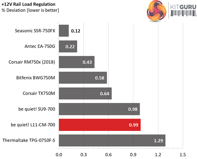
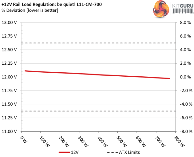
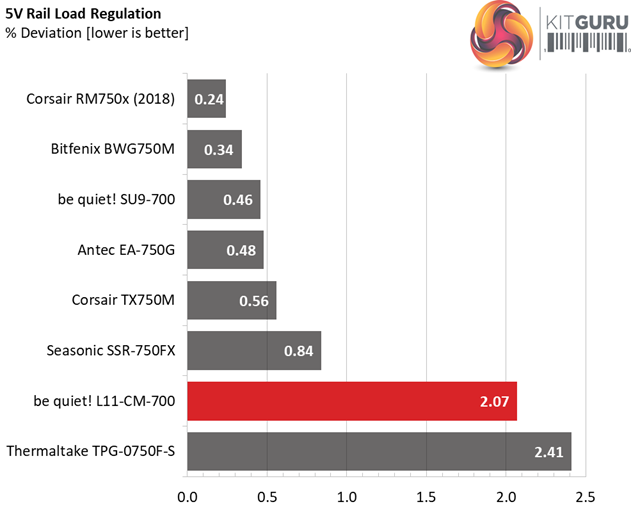
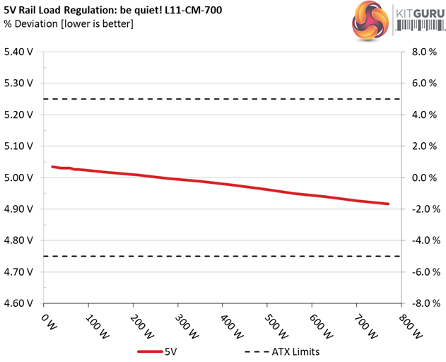
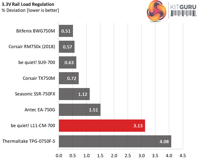
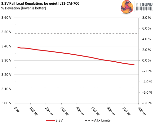
The load regulation at +12V cannot compete with units that feature half or full-bridge topologies, however still it is within 1% so it is satisfactory. The voltage deviations on the rest rails are notable, under increased loads.
The registered efficiency levels meet the corresponding 80 PLUS Gold requirements with 20% and 50% of the unit's max-rated load, while with full load efficiency cannot reach 87%. Nonetheless, we apply a huge stress with an over 45°C ambient, so inevitably the PSU's efficiency takes a big hit.
Despite of the 40°C rating, we cranked up the heat inside the hotbox at up to 47°C and everything went smooth. Even under very tough conditions the cooling fan spins at low speeds, with the output noise remaining at equally low levels.
Efficiency
Our efficiency testing procedure is detailed here.
Using results from the previous page, we plotted a chart showing the L11-CM-700’s efficiency at low loads, and loads from 10 to 110 percent of its maximum-rated capacity.
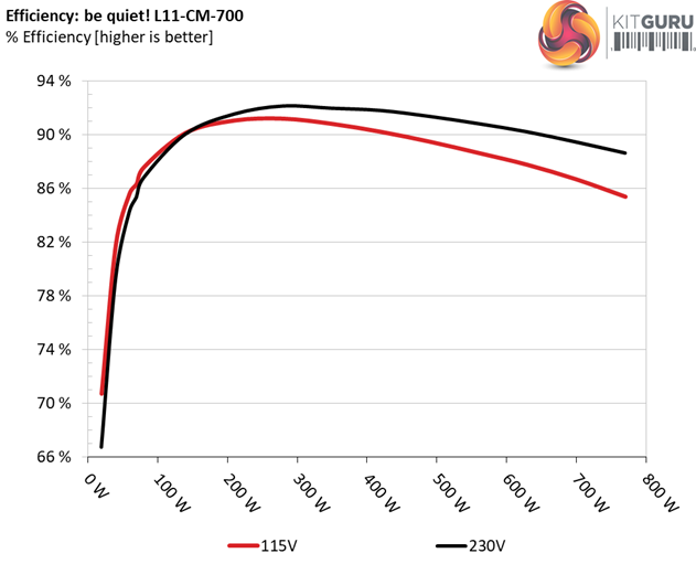
The efficiency levels are pretty high under both light and normal loads. The ACRF topology indeed delivers what FSP and be quiet! promises, in this section at least.
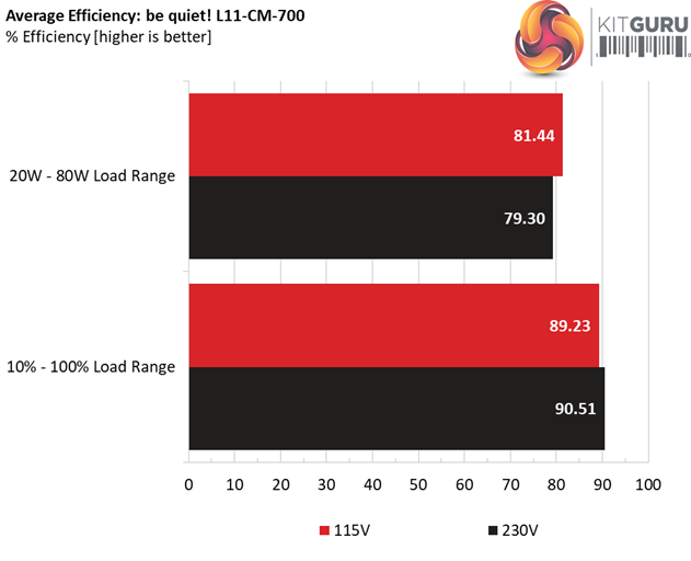
Efficiency At Low Loads
In the following tests, we measure the L11-CM-700's efficiency at loads significantly lower than 10 percent of its maximum capacity (the lowest load the 80 PLUS standard measures). The loads we dial are 20, 40, 60, and 80W. This is important for representing when a PC is idle, with power-saving features turned on.
| Test # | 12V | 5V | 3.3V | 5VSB | DC/AC (Watts) | Efficiency | Fan Speed (RPM) | PSU Noise (dB[A]) | PF/AC Volts |
| 1 | 1.195A | 0.497A | 0.472A | 0.196A | 19.575 | 70.727% | 677 | 11.5 | 0.836 |
| 12.112V | 5.035V | 3.391V | 5.100V | 27.677 | 115.05V | ||||
| 2 | 2.453A | 0.994A | 0.972A | 0.393A | 39.992 | 81.845% | 681 | 12.4 | 0.885 |
| 12.107V | 5.030V | 3.387V | 5.093V | 48.863 | 115.04V | ||||
| 3 | 3.636A | 1.491A | 1.446A | 5.087A | 59.410 | 85.605% | 682 | 12.4 | 0.906 |
| 12.104V | 5.030V | 3.387V | 5.087V | 69.400 | 115.05V | ||||
| 4 | 4.896A | 1.987A | 1.949A | 0.787A | 79.824 | 87.568% | 684 | 12.5 | 0.922 |
| 12.100V | 5.026V | 3.385V | 5.080V | 91.157 | 115.05V |
The fan spins at very low speeds and the unit's efficiency is high during all four light load tests that we conduct.
5VSB Efficiency
The ATX specification (revision 1.4), along with CEC, ErP Lot 3 2014 and ErP Lot 6 2010/2013, states that the 5VSB standby supply efficiency should be as high as possible, recommending 75 percent or higher with 550mA, 1A, and 1.5A of load.
The supply should also achieve higher than 75% efficiency at 5VSB under full load, or with 3A if its max current output on this rail is higher than 3A.
We take six measurements: one each at 100, 250, 550, 1000, and 1500mA, and one with the full load the 5VSB rail can handle.
| Test # | 5VSB | DC/AC (Watts) |
Efficiency | PF/AC Volts |
| 1 | 0.100A | 0.510 | 73.066% | 0.124 |
| 5.101V | 0.698 | 115.05V | ||
| 2 | 0.250A | 1.275 | 78.413% | 0.233 |
| 5.098V | 1.626 | 115.05V | ||
| 3 | 0.550A | 2.801 | 79.393% | 0.329 |
| 5.092V | 3.528 | 115.05V | ||
| 4 | 1.000A | 5.083 | 78.490% | 0.382 |
| 5.082V | 6.476 | 115.06V | ||
| 5 | 1.500A | 7.609 | 80.553% | 0.408 |
| 5.072V | 9.446 | 115.05V | ||
| 6 | 3.000A | 15.122 | 78.642% | 0.453 |
| 5.040V | 19.229 | 115.06V |
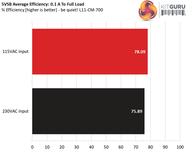
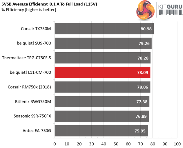
Satisfactory efficiency from the 5VSB circuit, however we know that FSP can do better here. Obviously its engineers avoided using a more advanced circuit, to keep the production cost under control.
Power Consumption In Idle And Standby
In the table below, you’ll find the power consumption and voltage values of all rails (except -12V) when the PSU is idle (powered on, but without any load on its rails), and the power consumption when the unit is in standby mode (without any load, at 5VSB).
| Mode | 12V | 5V | 3.3V | 5VSB | Watts | PF/AC Volts |
| Idle | 12.116V | 5.048V | 3.396V | 5.104V | 7.952 | 0.667 |
| 115.1V | ||||||
| Standby | 0.100 | 0.020 | ||||
| 115.1V | ||||||
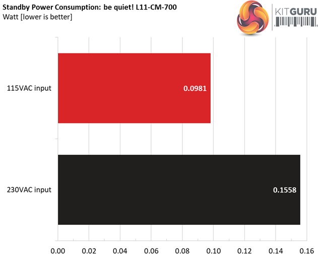
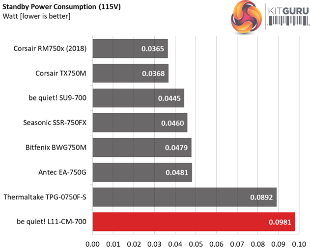
The vampire power is increased with both 115V and 230V input.
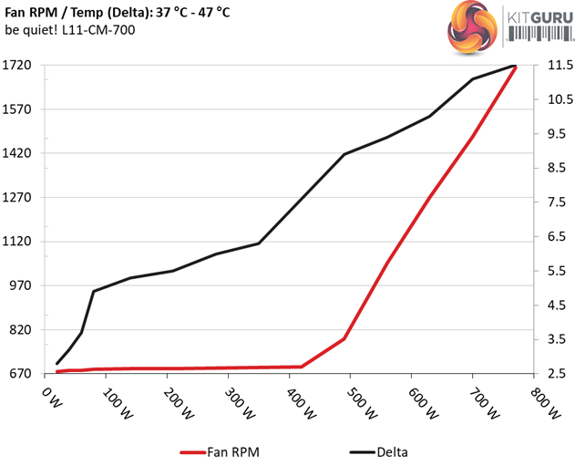
Fan RPM, Delta Temperature, And Output Noise
Our mixed noise testing is described in detail here.
The first chart below illustrates the cooling fan's speed (in RPM), and the delta between input and output temperature. The results were obtained at 37°C (98.6°F) to 47°C (116.6°F) ambient temperature.
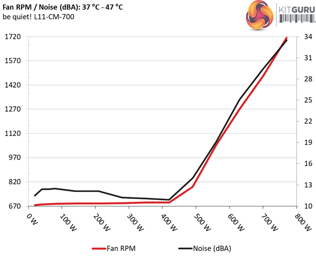
The next chart shows the cooling fan's speed (again, in RPM) and output noise. We measure acoustics from one meter away, inside a hemi-anechoic chamber. Background noise inside the chamber is below 6 dB(A) during testing (it's actually much lower, but our sound meter’s microphone hits its floor), and the results are obtained with the PSU operating at 37°C (98.6°F) to 47°C (116.6°F) ambient temperature.
The following graph illustrates the fan's output noise over the PSU's operating range. The same conditions of the above graph apply to our measurements, though the ambient temperature is between 30°C (86°F) to 32°C (89.6°F).
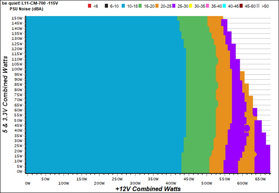
The PSU's noise is low, throughout its entire operation range. Up to 440W the acoustics noise is within the 10-15 dB(A) range, while in the worst case scenario we measure less than 30 dB(A).
Protection Features
Our protection features evaluation methodology is described in detail here.
|
Protection Features |
|
|
OCP |
12V: 73A (130.36%), 11.662V |
|
OPP |
891.7W (127.39%) |
|
OTP |
✓ (120°C @ 12V Heatsink) |
|
SCP |
12V: ✓ |
|
PWR_OK |
Proper Operation |
|
NLO |
✓ |
|
SIP |
Surge: MOV |
The OCP triggering point at +12V is properly set, however this is not the case on the minor rails. In the 3.3V rail we have to go up to 39.5A till the over current protection intervenes. This is just too high!
The over power and over temperature protections are working well, while all rails are protected against possible short circuits. Finally, the power ok signal is accurate and lasts long.
DC Power Sequencing
According to Intel’s most recent Power Supply Design Guide (revision 1.4) the +12V and 5V voltages must be equal or greater than the 3.3V rail’s output at all times, during the power-up and normal operation. For our first measurement, we turn the unit off and switch it back on without any load in any of the rails.
In the second test, we set the PSU to standby mode, dial full load and start it afterwards. In the last test, while the power supply is completely switched off (we cut off the power or switch the supply off through its power switch), we dial full load before restoring power.
We notice a small problem here during the second test, where the 3.3V rail for a very short period has a higher voltage level than the 5V rail. There should be a clear distinction between 5V and 3.3V.
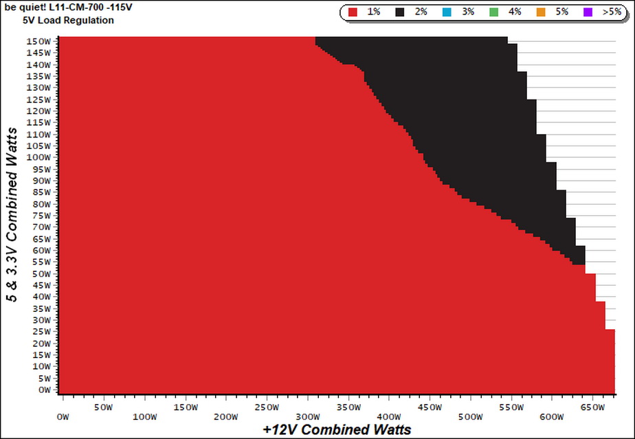
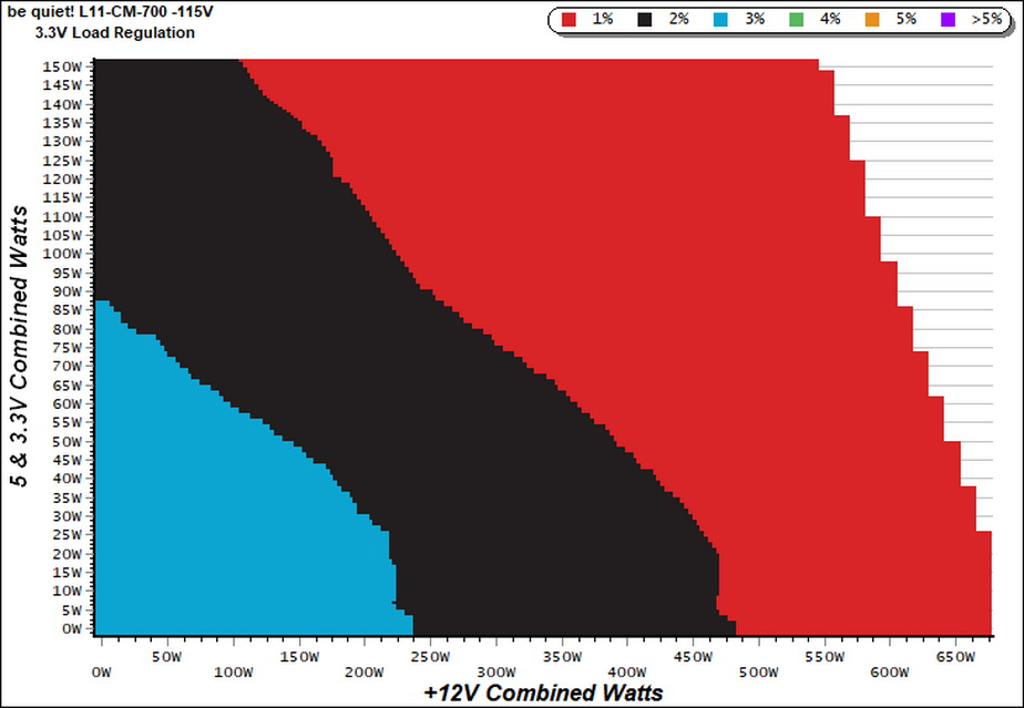
Our cross-load tests are described in detail here.
To generate the following charts, we set our loaders to auto mode through our custom-made software before trying more than 1500 possible load combinations with the +12V, 5V, and 3.3V rails. The load regulation deviations in each of the charts below are calculated by taking the nominal values of the rails (12V, 5V, and 3.3V) as point zero. The ambient temperature is between at 30°C (86°F) to 32°C (89.6°F).
Load Regulation Charts
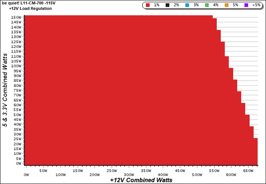
Efficiency Chart
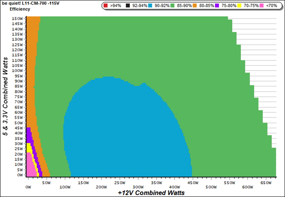
The high efficiency region is from 120W to around 450W at +12V, with the load on the minor rails staying below 95W. In the majority of its operating range the unit delivers within 85-90% efficiency.
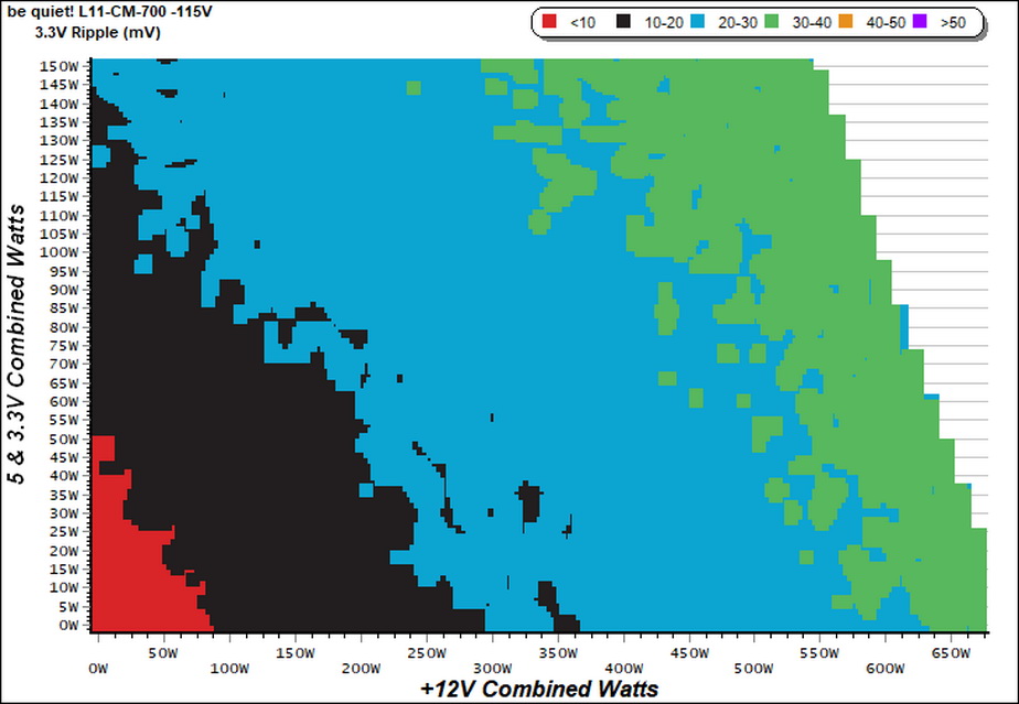
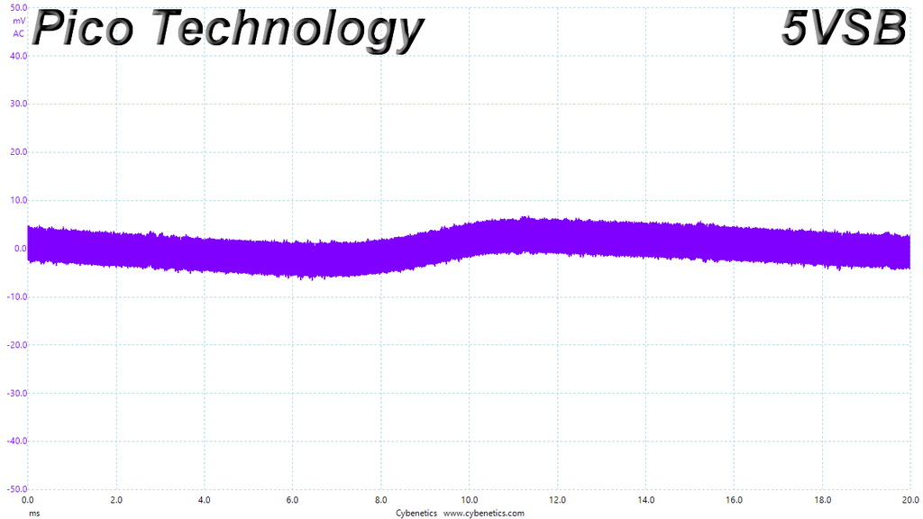
Ripple Charts
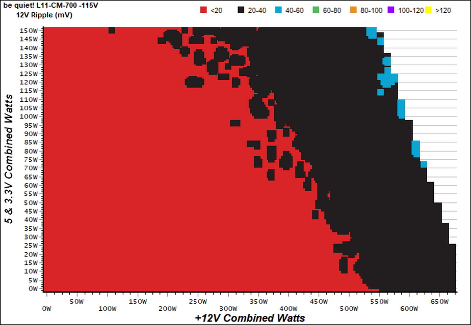
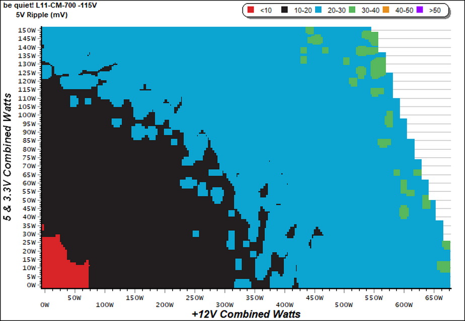
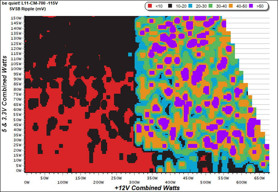
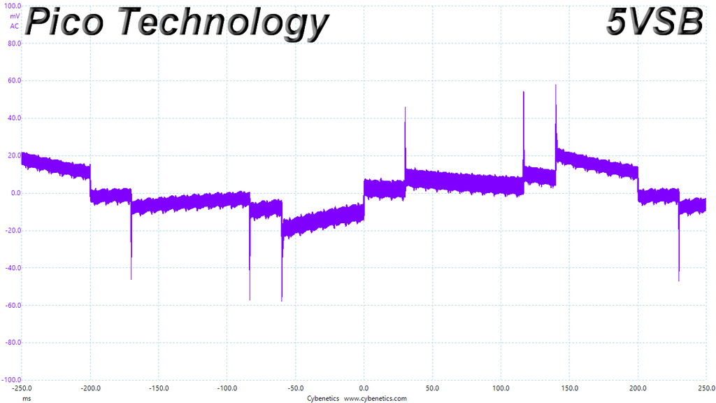
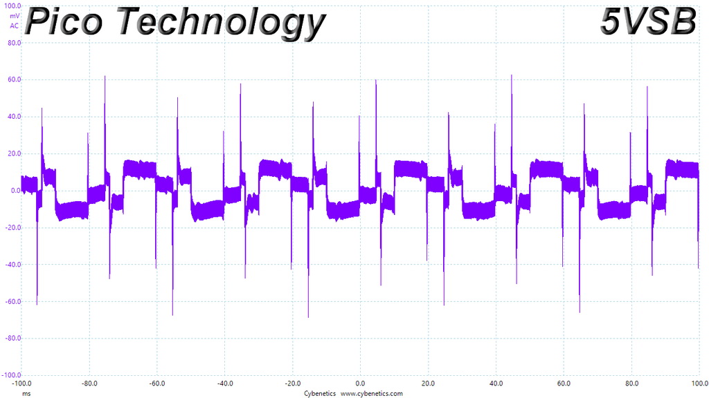
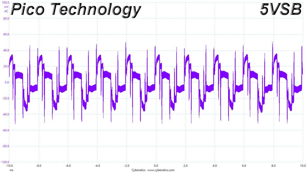
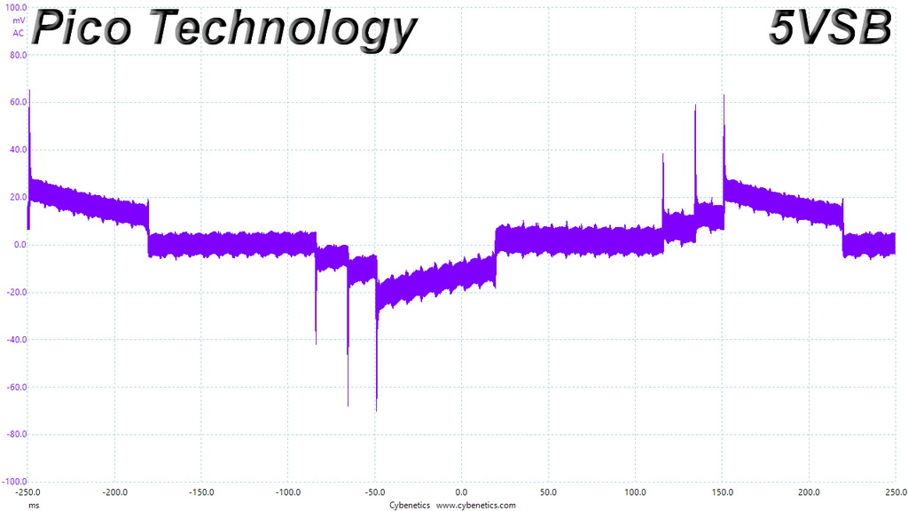
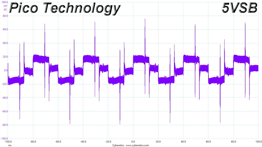
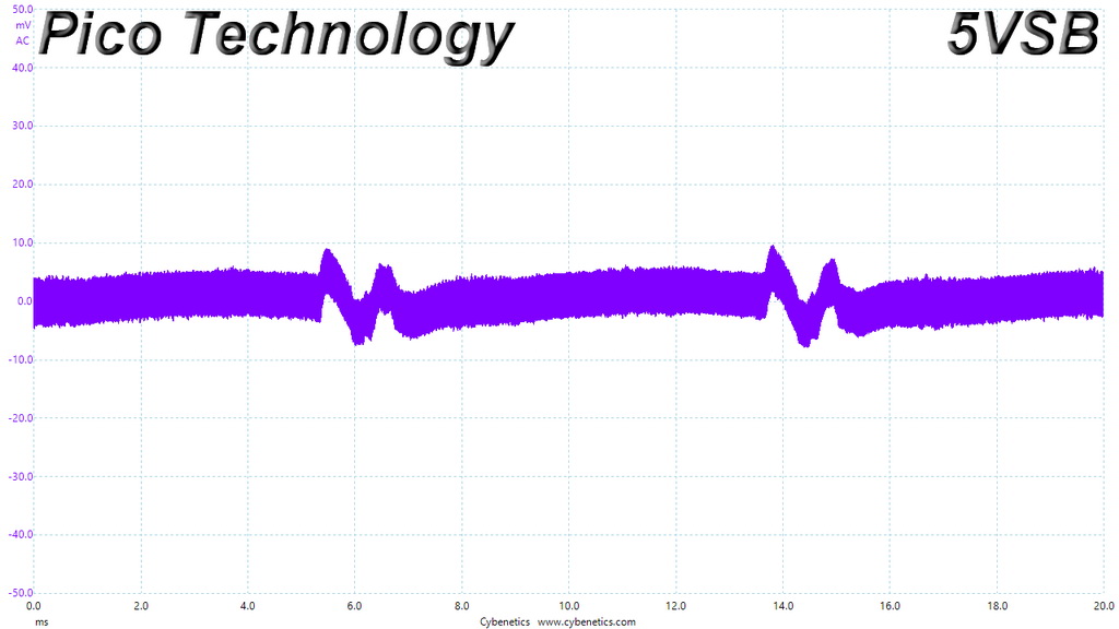
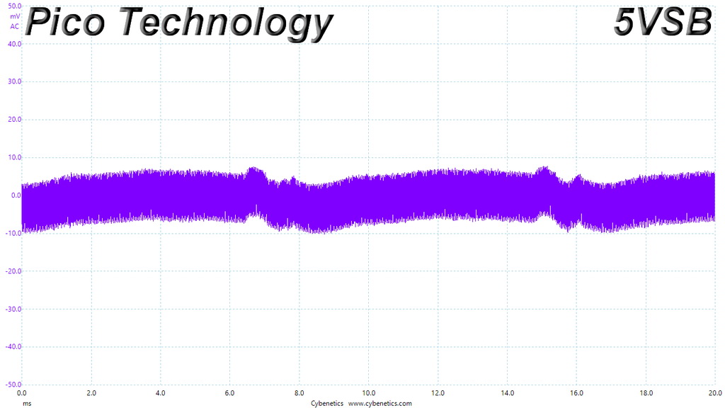
The 5VSB rail's ripple graph is colorful! The vivid colors might look nice, but actually depict a ripple suppression problem.
Infrared Images
We apply half-load for 10 minutes with the PSU’s top cover and cooling fan removed before taking photos with our modified FLIR E4 camera that delivers 320×240 IR resolution (76,800 pixels).
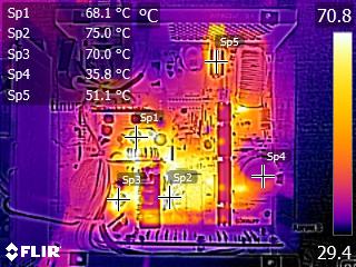
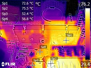
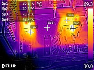
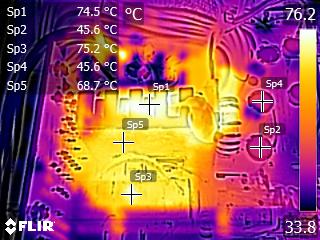
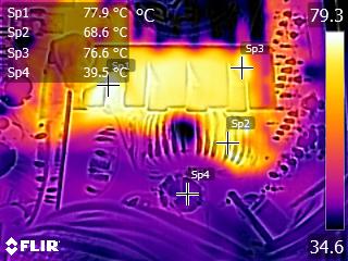
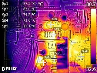
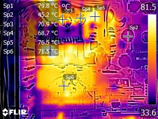
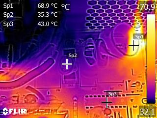
The caps close to the chokes of the secondary side get quite hot, and this can be a problem since they belong to Teapo's mainstream SC line. Other than that, we don't spot anything strange in those IR shots. The temperatures in the rest components are kept at normal levels, considering this platform's efficiency.
Advanced Transient Response Tests
For details on our transient response testing, please click here.
These tests are crucial because they simulate the transient loads a PSU is likely to handle (such as booting a RAID array or an instant 100 percent load of CPU/GPUs). We call these “Advanced Transient Response Tests” and they are designed to be very tough to master, especially for a PSU with a capacity of less than 500W.
In all of the tests, we use an oscilloscope to measure the voltage drops caused by the transient load. The voltages should remain within the ATX specification's regulation limits.
We should note that the ATX spec requires for capacitive loading during the transient rests, but in our methodology we chose to apply the worst case scenario with no extra capacitance on the rails.
Advanced Transient Response at 20 Percent – 200ms
| Voltage | Before | After | Change | Pass/Fail |
|---|---|---|---|---|
| 12V | 12.089V | 11.917V | 1.42% | Pass |
| 5V | 5.027V | 4.844V | 3.64% | Pass |
| 3.3V | 3.380V | 3.175V | 6.07% | Pass |
| 5VSB | 5.061V | 4.998V | 1.24% | Pass |
Advanced Transient Response at 20 Percent – 20ms
| Voltage | Before | After | Change | Pass/Fail |
|---|---|---|---|---|
| 12V | 12.087V | 11.839V | 2.05% | Pass |
| 5V | 5.034V | 4.834V | 3.97% | Pass |
| 3.3V | 3.384V | 3.161V | 6.59% | Pass |
| 5VSB | 5.060V | 4.991V | 1.36% | Pass |
Advanced Transient Response at 20 Percent – 1ms
| Voltage | Before | After | Change | Pass/Fail |
|---|---|---|---|---|
| 12V | 12.088V | 11.885V | 1.68% | Pass |
| 5V | 5.032V | 4.808V | 4.45% | Pass |
| 3.3V | 3.383V | 3.164V | 6.47% | Pass |
| 5VSB | 5.060V | 5.008V | 1.03% | Pass |
Advanced Transient Response at 50 Percent – 200ms
| Voltage | Before | After | Change | Pass/Fail |
|---|---|---|---|---|
| 12V | 12.053V | 11.880V | 1.44% | Pass |
| 5V | 5.014V | 4.819V | 3.89% | Pass |
| 3.3V | 3.360V | 3.144V | 6.43% | Pass |
| 5VSB | 5.021V | 4.952V | 1.37% | Pass |
Advanced Transient Response at 50 Percent – 20ms
| Voltage | Before | After | Change | Pass/Fail |
|---|---|---|---|---|
| 12V | 12.053V | 11.814V | 1.98% | Pass |
| 5V | 5.009V | 4.791V | 4.35% | Pass |
| 3.3V | 3.357V | 3.106V | 7.48% | Fail |
| 5VSB | 5.022V | 4.943V | 1.57% | Pass |
Advanced Transient Response at 50 Percent – 1ms
| Voltage | Before | After | Change | Pass/Fail |
|---|---|---|---|---|
| 12V | 12.053V | 11.894V | 1.32% | Pass |
| 5V | 5.008V | 4.801V | 4.13% | Pass |
| 3.3V | 3.356V | 3.111V | 7.30% | Fail |
| 5VSB | 5.022V | 4.960V | 1.23% | Pass |
![]()
![]()
![]()
![]()
![]()
The transient response of the +12V rail is decent, while at 5V we would like to see a within 3% deviations. On the 3.3V rail the performance is mediocre, to say the least, since we measure over 7% deviations in two tests. Finally, the 5VSB rail performs good enough.
We didn't expect to get top results here, because of the ACRF topology.
Here are the oscilloscope screenshots we took during Advanced Transient Response Testing:
Transient Response At 20 Percent Load – 200ms

Transient Response At 20 Percent Load – 20ms

Transient Response At 20 Percent Load – 1ms
Transient Response At 50 Percent Load – 200ms
Transient Response At 50 Percent Load – 20ms
Transient Response At 50 Percent Load – 1ms

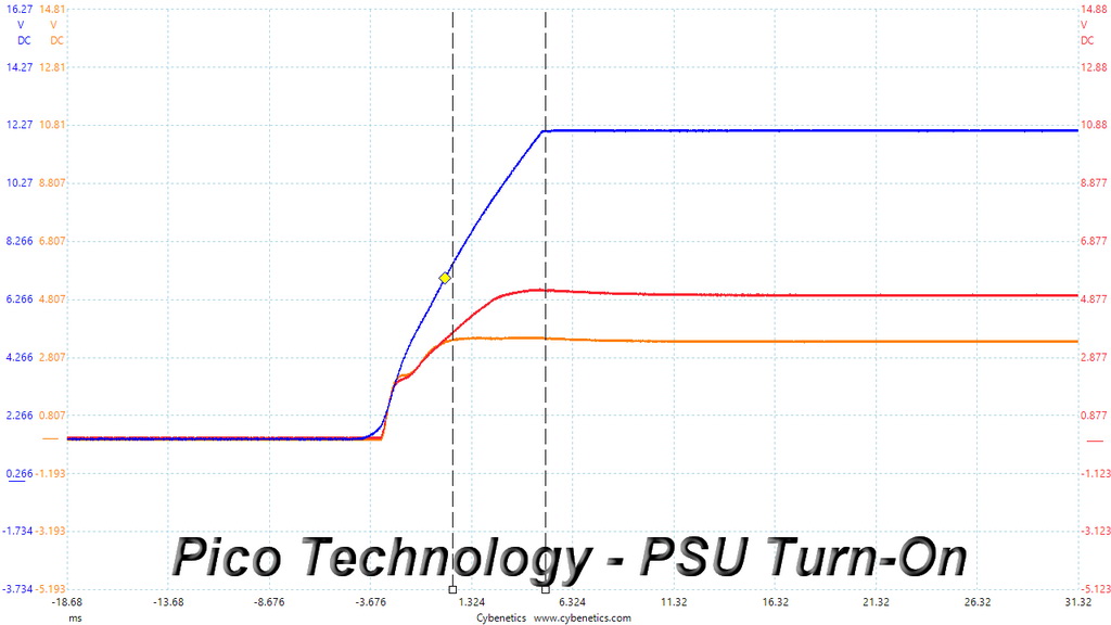
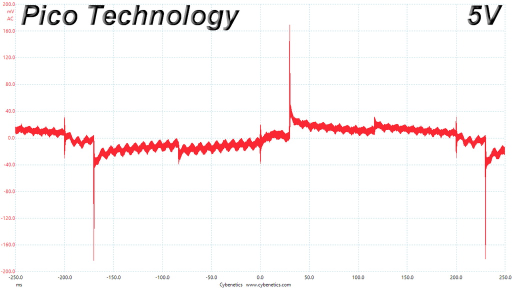
Turn-On Transient Tests
In the next set of tests, we measure the L11-CM-700’s response in simpler transient load scenarios—during its power-on phase.
For our first measurement, we turn the L11-CM-700 off, dial in the maximum current the 5VSB rail can handle, and switch the PSU back on.
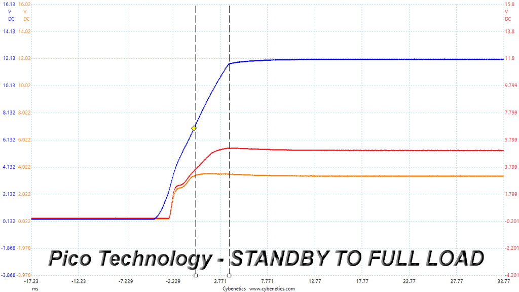
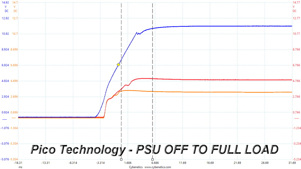
In the second test, we dial the maximum load the +12V rail can handle and start the PSU while it is in standby mode. In the last test, while the PSU is completely switched off (we cut off the power or switch the PSU off through its power switch), we dial the maximum load the +12V rail can handle before restoring power. The ATX specification states that recorded spikes on all rails should not exceed 10 percent of their nominal values (+10 percent for 12V is 13.2V, and 5.5V for 5V).
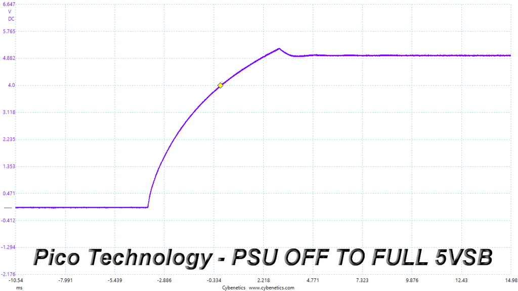
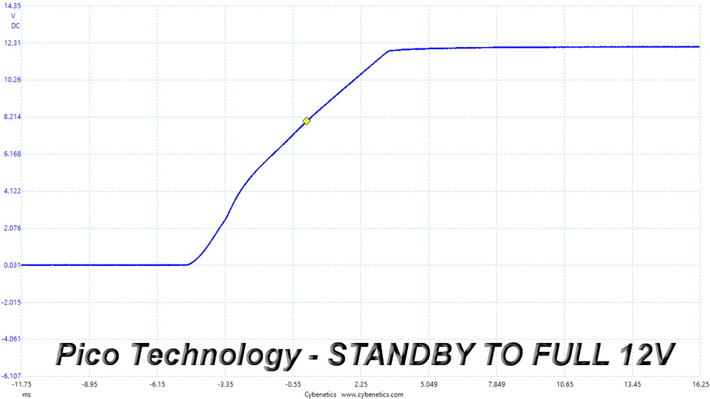
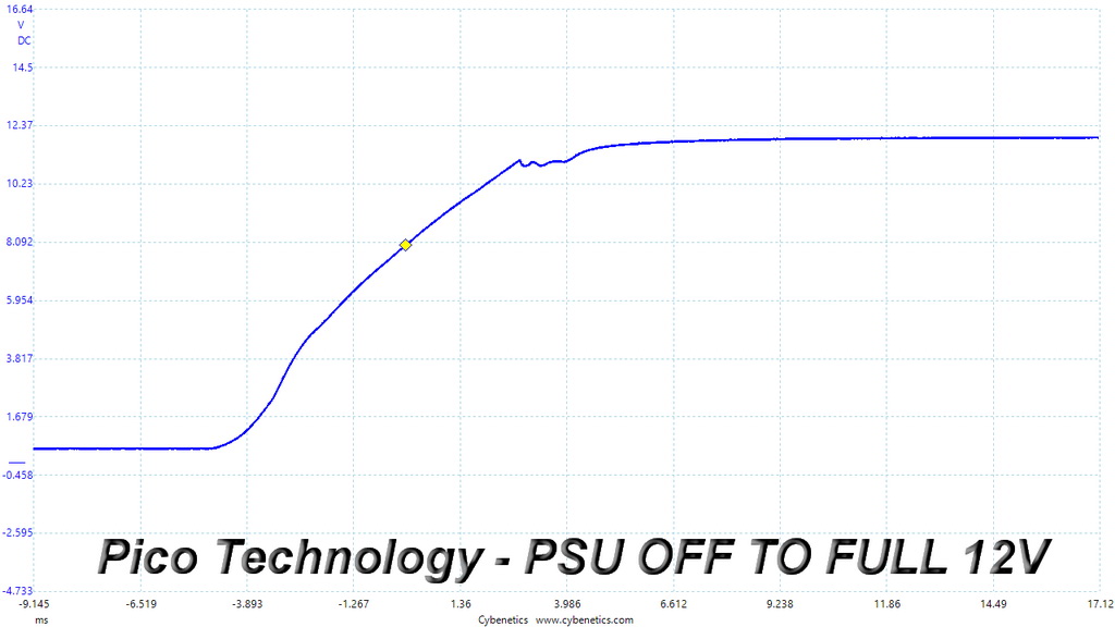
We notice a voltage overshoot at 5VSB which is around 5.2V so it is within the limits. The slopes in the rest two tests are quote smooth.
To learn how we measure ripple, please click here.
The following table includes the ripple levels we measured on the L11-CM-700's rails. The limits, according to the ATX specification, are 120mV (+12V) and 50mV (5V, 3.3V, and 5VSB).
| Test | 12V | 5V | 3.3V | 5VSB | Pass/Fail |
| 10% Load | 5.7 mV | 12.7 mV | 11.6 mV | 15.5 mV | Pass |
| 20% Load | 13.1 mV | 17.4 mV | 17.3 mV | 18.5 mV | Pass |
| 30% Load | 16.6 mV | 19.9 mV | 21.5 mV | 17.9 mV | Pass |
| 40% Load | 18.0 mV | 21.9 mV | 22.7 mV | 11.4 mV | Pass |
| 50% Load | 20.8 mV | 24.7 mV | 25.4 mV | 12.5 mV | Pass |
| 60% Load | 21.8 mV | 26.2 mV | 28.4 mV | 11.4 mV | Pass |
| 70% Load | 24.1 mV | 27.6 mV | 32.2 mV | 14.5 mV | Pass |
| 80% Load | 25.7 mV | 30.9 mV | 33.6 mV | 15.6 mV | Pass |
| 90% Load | 33.3 mV | 33.0 mV | 36.5 mV | 16.6 mV | Pass |
| 100% Load | 43.3 mV | 35.8 mV | 41.6 mV | 18.2 mV | Pass |
| 110% Load | 59.6 mV | 37.9 mV | 44.4 mV | 19.9 mV | Pass |
| Crossload 1 | 18.2 mV | 27.5 mV | 24.4 mV | 19.3 mV | Pass |
| Crossload 2 | 39.0 mV | 33.8 mV | 37.5 mV | 18.9 mV | Pass |
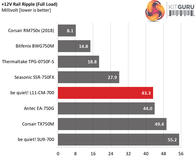
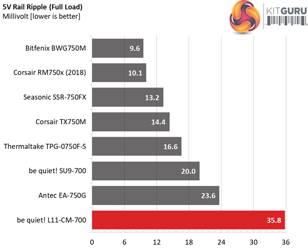

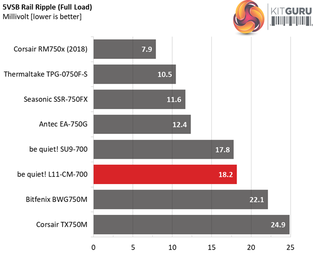
The ripple suppression cannot meet the competition in this price range, with both the Seasonic SSR-750FX and Bitfenix BWG750M units achieving much better results (with only exception the 5VSB rail where the BWG750M falls a bit behind).
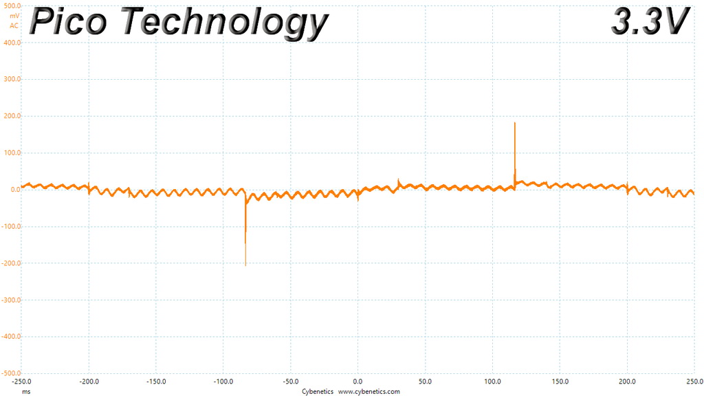
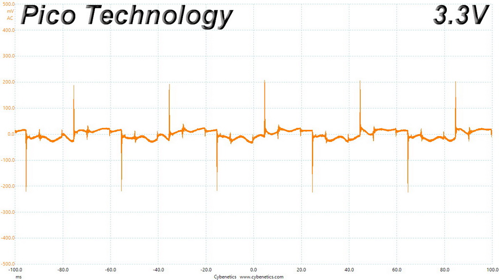
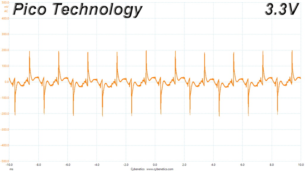
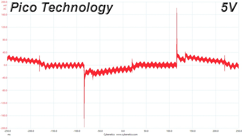
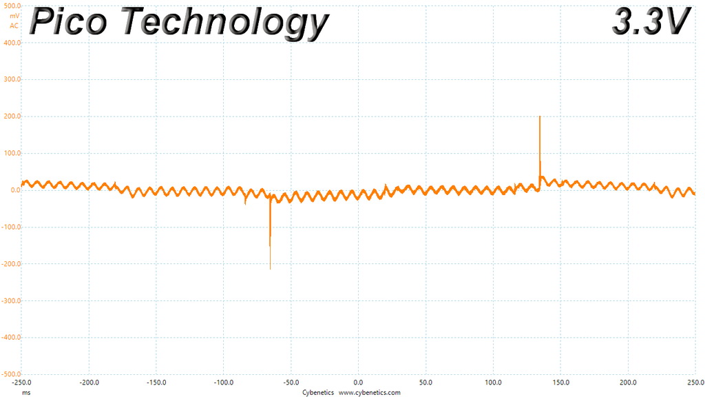
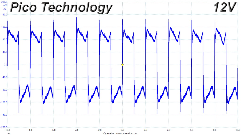
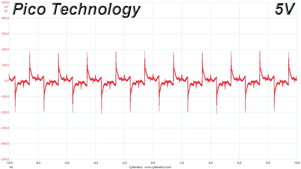
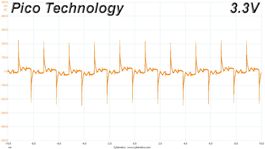
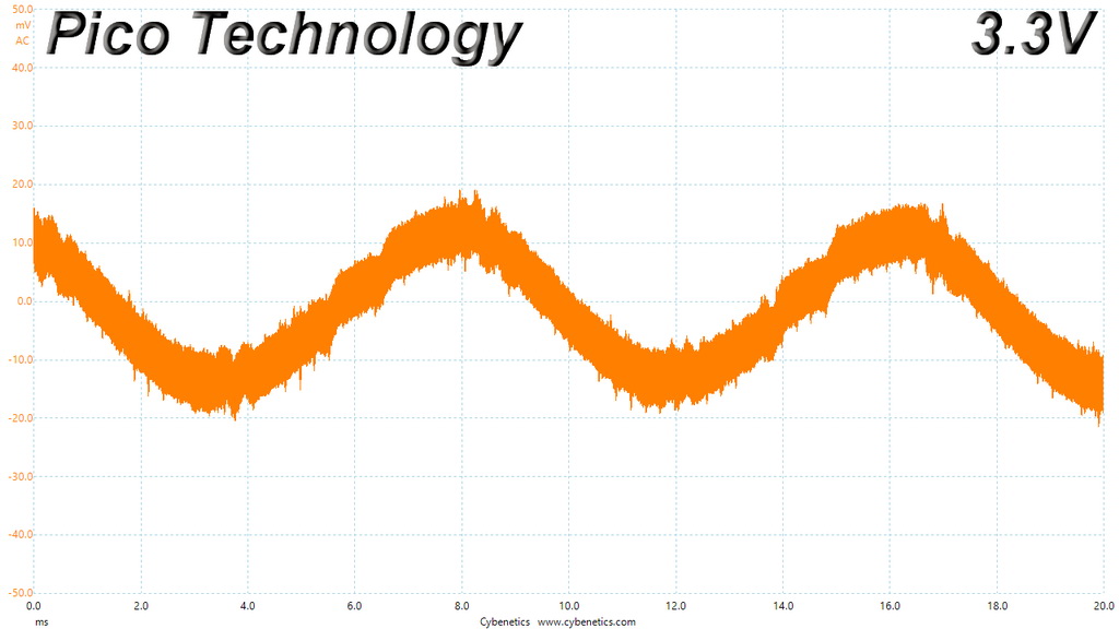
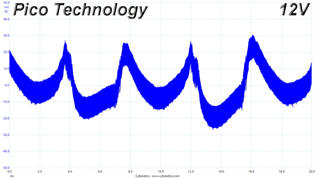
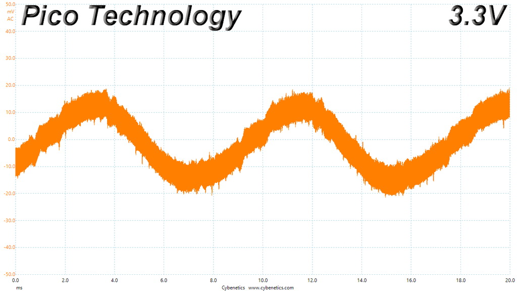
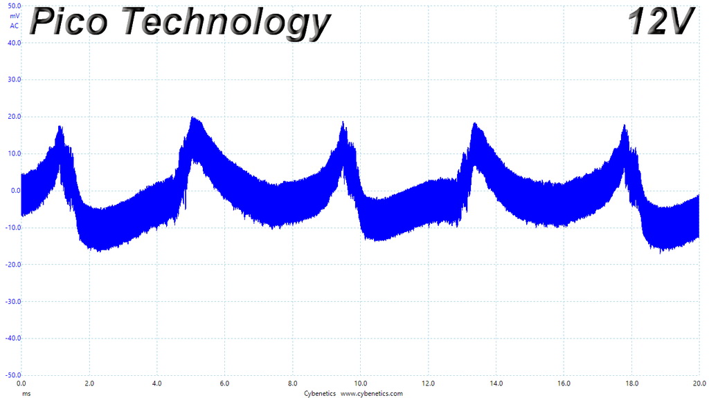
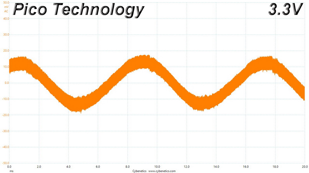
The +12V rail goes close to 45mV under full load at high ambient, which is a satisfactory result, however the minor rails, especially 3.3V, clearly need more filtering caps.
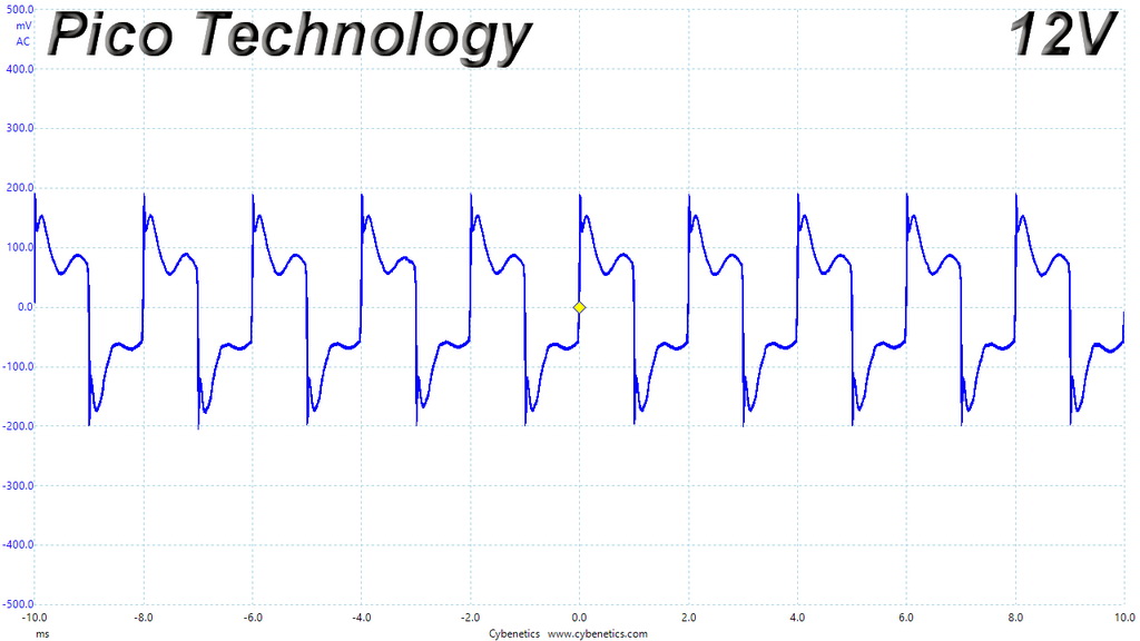
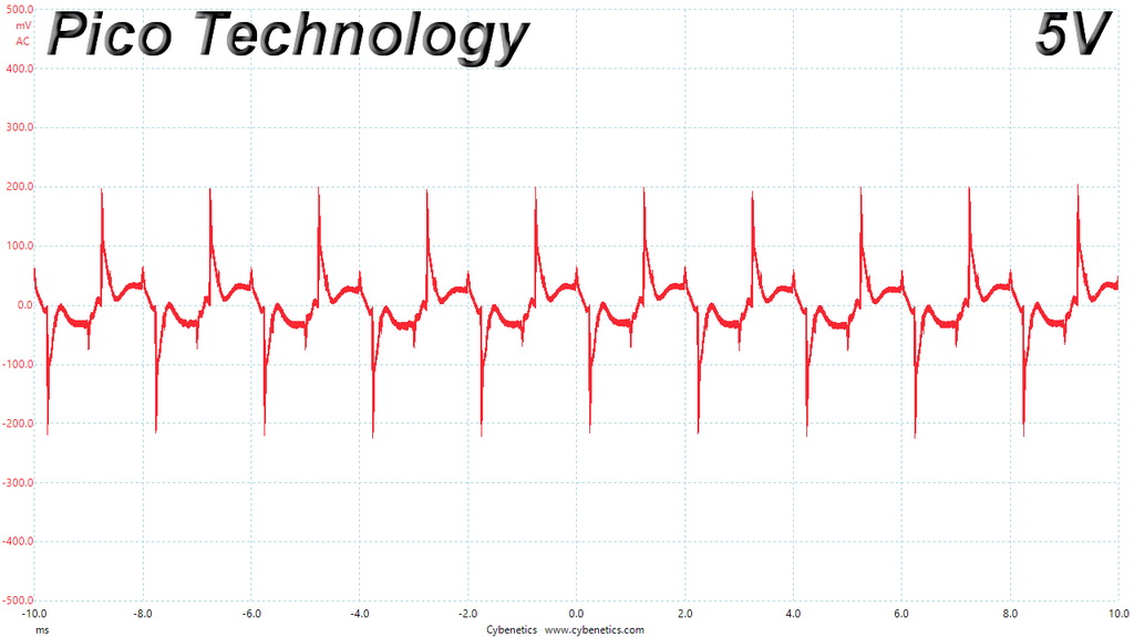
Ripple Oscilloscope Screenshots
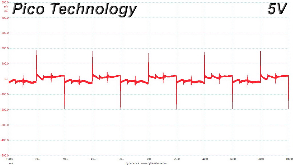
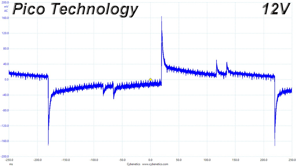
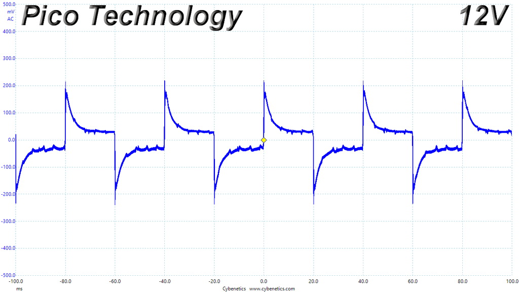
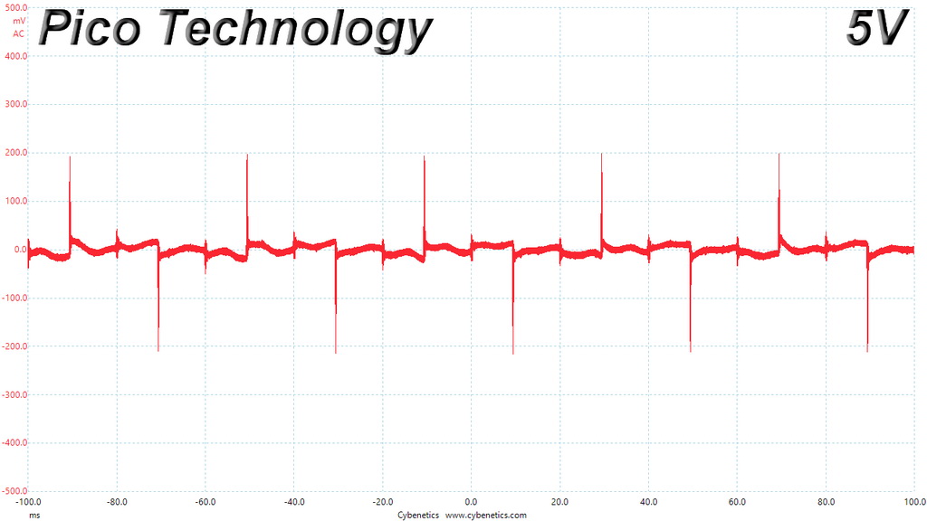
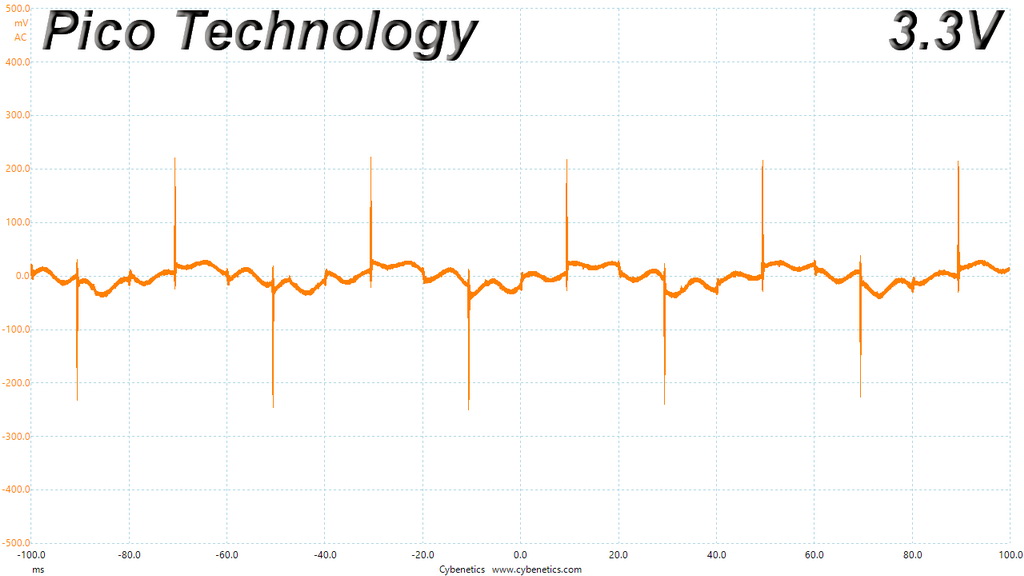
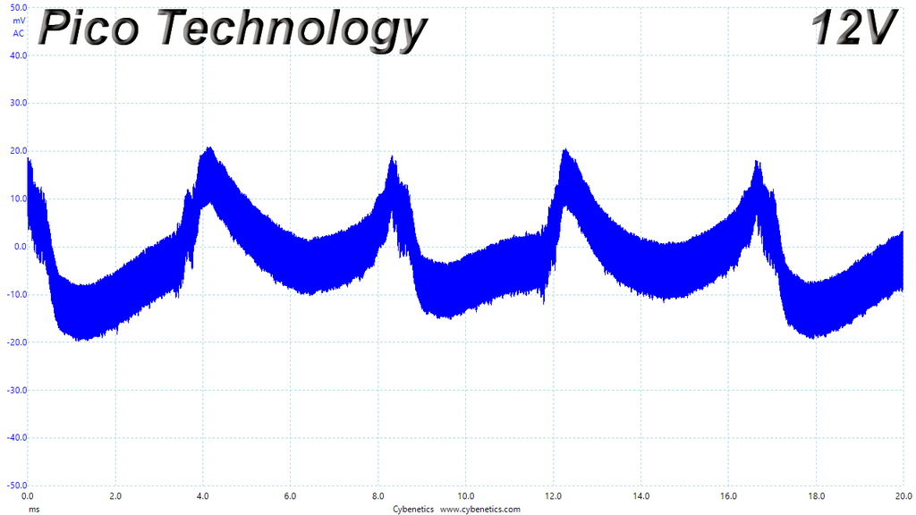
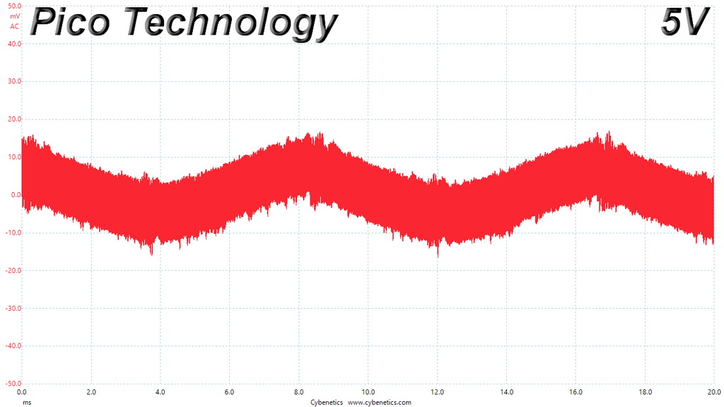
The following oscilloscope screenshots illustrate the AC ripple and noise registered on the main rails (+12V, 5V, 3.3V and 5VSB). The bigger the fluctuations on the screen, the bigger the ripple/noise. We set 0.01 V/Div (each vertical division/box equals 0.01V) as the standard for all measurements.
Ripple At Full Load
Ripple At 110-Percent Load

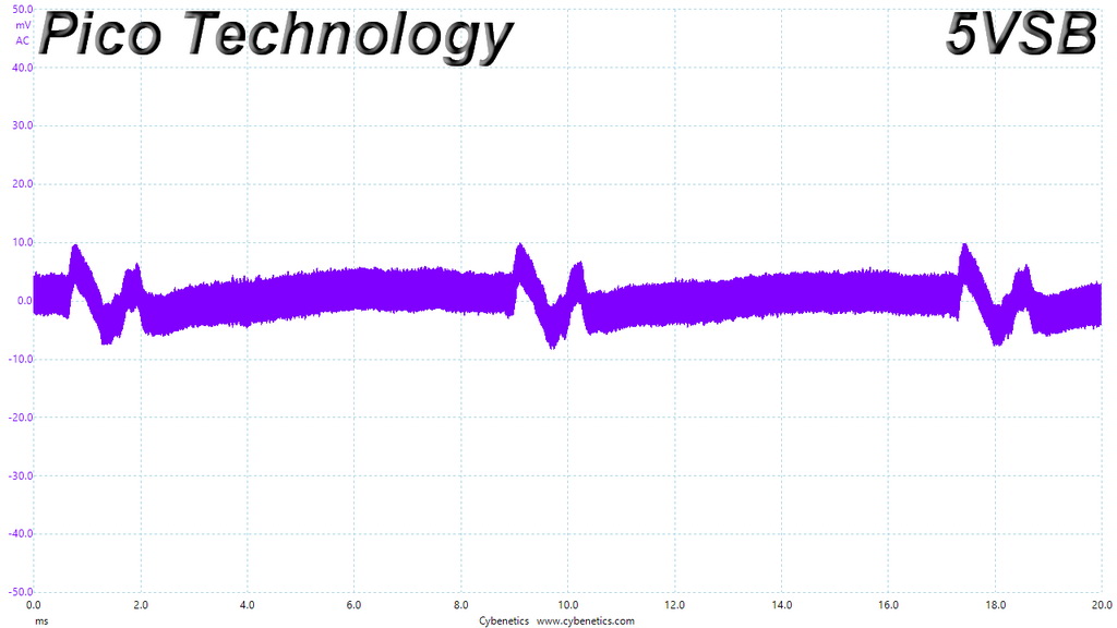
Ripple At Cross-Load 1

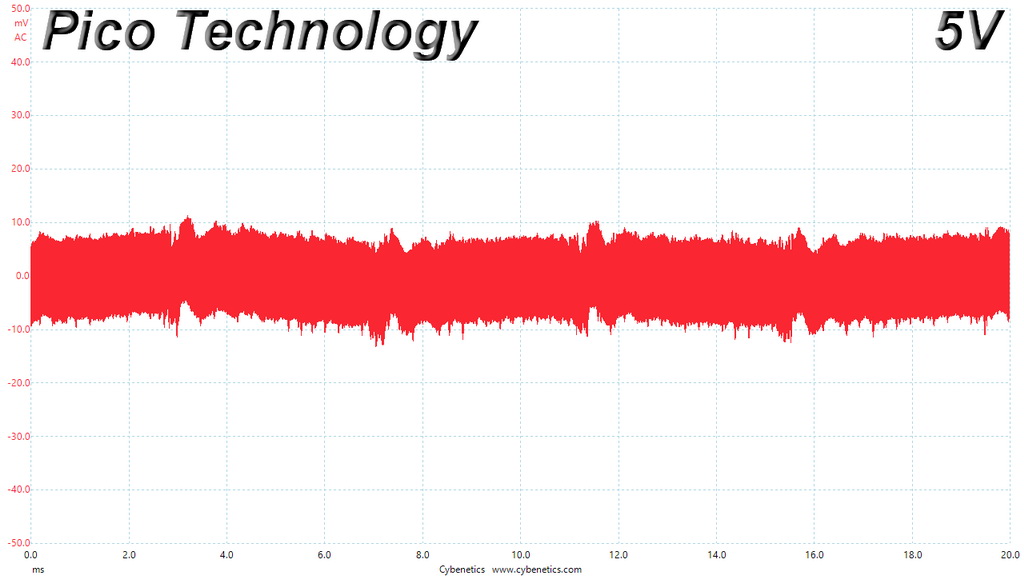
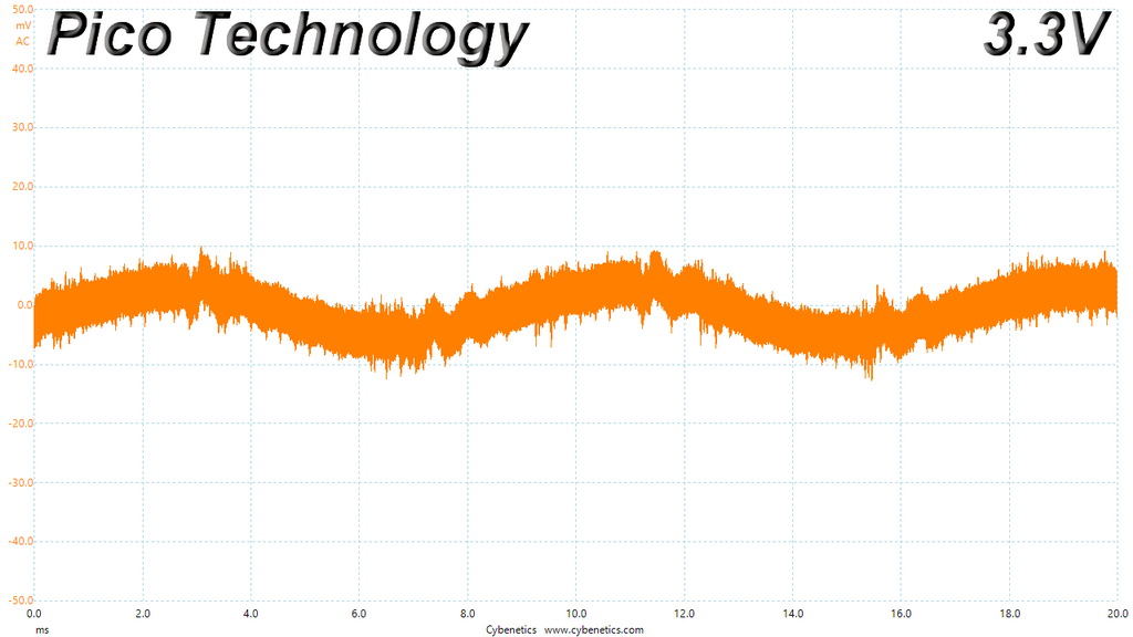
Ripple At Cross-Load 2

To learn more about our EMI testing equipment, please check out How We Test Power Supply Units.
EMI Results
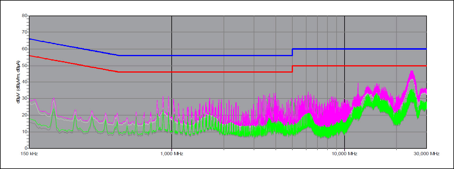
Low conducted EMI emissions through out the entire frequency range. The EMI filter does a splendid job!
Performance Rating
The following graph shows the L11-CM-700’s total performance rating, comparing it to other units we have tested. To be more specific, the tested unit is shown as 100 percent, and every other unit's performance is shown relative to it.
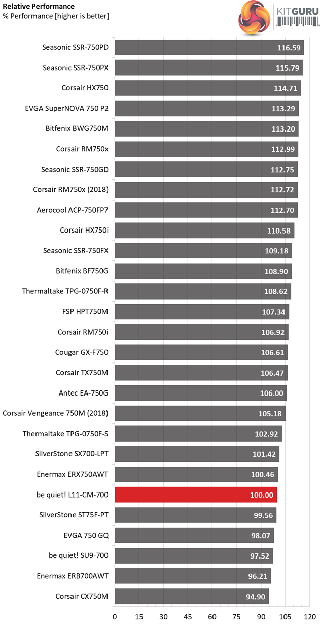
The overall performance is not high, with the SSR-750FX and the BWG750M being way ahead. Even the Corsair Vengeance 750M, which has similar specs, achieves a notably higher score.
Performance Per Dollar
The following chart may be the most interesting to many of you because it depicts the product’s performance-per-dollar score. We looked up the current price of each PSU on popular online shops and used those prices and all relative performance numbers to calculate the index. Note that all of the numbers in the following graphs are normalized by the rated power of each unit.
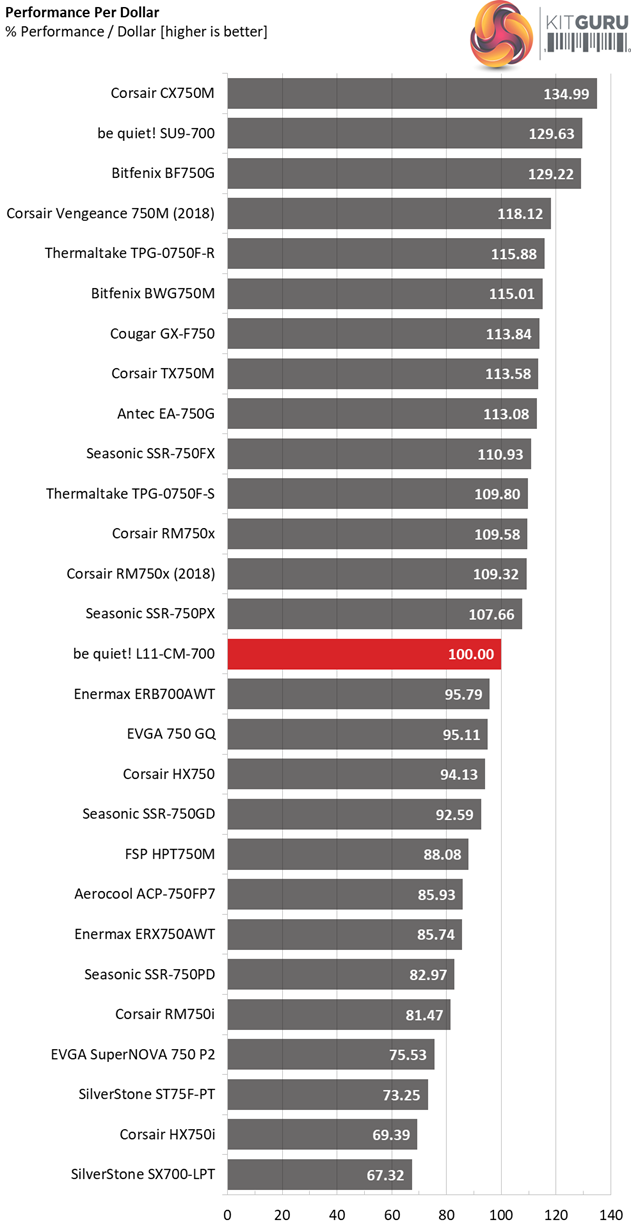
With a close to 100 dollars price tag the performance per buck is not so competitive. With the same amount someone can get a Seasonic Focus Plus Gold 750W or the similar capacity Bitfenix Whisper M, with both units offering higher performance and a longer warranty.
Noise Rating
The graph below depicts the cooling fan's average noise over the PSU's operating range, with an ambient temperature between 30°C and 32°C (86°F to 89.6°F).
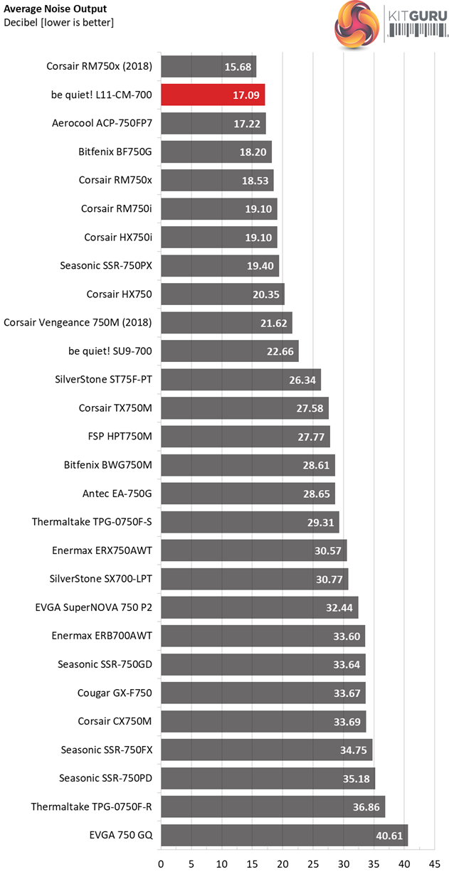
When it comes to noise output, the L11-CM-700 honors its brand's name since it is super quiet. Only the, more expensive, Corsair RM750x (2018) manages to outperform it in this section.
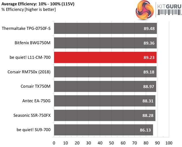
Efficiency Rating
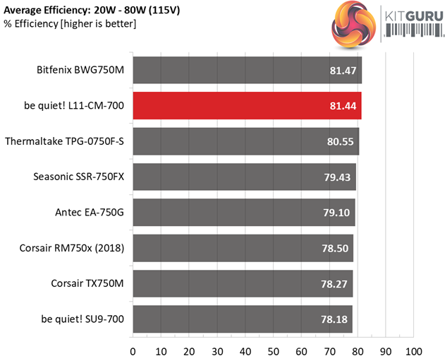
The following graph shows the PSU's average efficiency throughout its operating range, with an ambient temperature close to 30°C.
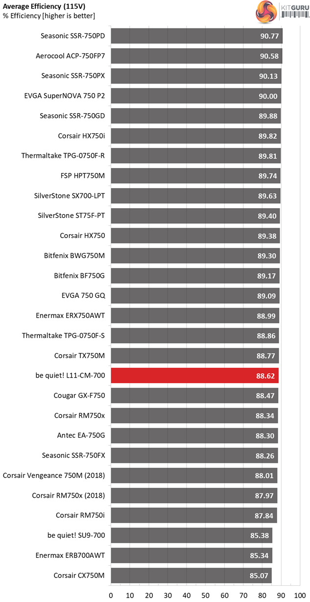
The ACRF topology delivers what it promises, ETA-A and 80 PLUS Gold efficiency levels.
The be quiet! Pure Power 11 700W will be offered at around $100 in the US while in the UK market is sold for £96.95, at OverClockers UK
The Pure Power line is frequently updated, although power supplies tend to be kept in production for quite long without any changes. We are all used to seeing products like smartphones getting yearly updates but as it seems be quiet! wishes to bring a new era in power supplies as well. This is not a bad thing, definitely, since through often platform updates you can achieve higher performance and increased reliability.
The truth is though that the technology in this technology sector doesn't move at a fast pace. The most interesting innovation that I have noticed in the last couple of years is the GaN technology, which for the moment is only used in high-end and super-expensive power supplies such as the Corsair AX1600i.
Compared to the previous model, the L11-CM-700 offers higher efficiency (Gold instead of Silver) and it is also covered by a larger warranty (five vs three years). In my opinion though, FSP should abandon the Active Clamp Reset Forward topology and focus instead on half and full-bridge topologies, which achieve better performance.
Through ACRF it might be possible to offer a very long hold-up time without using a high capacity bulk cap which costs a lot, and you also reduce the number of parts needed in the primary side. That said the transient response is not so good and when it comes to PSUs the transient loads are what matter the most, since they are a major part of a system's daily routine. Only rarely will a PC apply a constant load. In the majority of cases the load-changing repetition rate will be high.
The L11-CM-700 features very quiet operation and it is efficient, however unfortunately it is also rather expensive in the UK. Right now the price difference in the UK against the SSR-750FX is around £8 – and the majority of users will prefer to pay this small amount to get the superior Seasonic offering. The Seasonic unit offers an extra 50W of power, has a fully modular cable design, Japanese caps and it is supported by a longer warranty.
If be quiet! wants to boost the sales of this power supply it is going to have to drop the price point by at least £10 or else it will have a very hard time keeping up with the competition. The fact is that Seasonic set the bar high with the Focus line, offering good performance at affordable prices so competitors have no option but to follow this example. If they want to remain in the game at least.
With a price of 80 pounds (including VAT) in the UK or 80 dollars (without VAT) in the US, the L11-CM-700 would get a higher rating but at its current (high) price point I have to compare it with strong competition, which offer more for the money.
Hopefully with the Pure Power 12 line be quiet! will force FSP to abandon the ACRF topology and move forward with a more capable design. A better choice of capacitors is also required.
![]()
You can get the be quiet! Pure Power 11 700W from Overclockers UK for £96.95 inc VAT HERE.
Pros:
- Full power at 47°C.
- Quiet operation.
- Long hold-up time.
- Accurate power ok signal.
- Complete protection features set.
- Low conducted EMI.
- Long enough warranty period (5-year).
Cons:
- Very high price for what it has to offer.
- Poor choice of bulk and filtering caps for a product of this price tag.
- High inrush currents and very high OCP triggering points at 5V and 3.3V.
- Mediocre transient response on the minor rails.
- The power distribution could be better.
- Found a small problem during the DC power sequencing tests.
- Single EPS connector (however it is sold as a mainstream unit so this is kind of expected).
- The protection inside the box is not optimal.
KitGuru says: At its current price point the be quiet! Pure Power 11 700W faces stiff competition as for similar amounts of money enthusiast users can get the similar capacity Seasonic Focus Plus Gold or the Bitfenix Whisper M – both of which feature higher performance and fully modular cable interfaces. With a 20 pounds/dollars lower price tag the L11-CM-700 would be much more appealing since it can easily meet the competition in this category. An added benefit is the whisper quiet operation.