
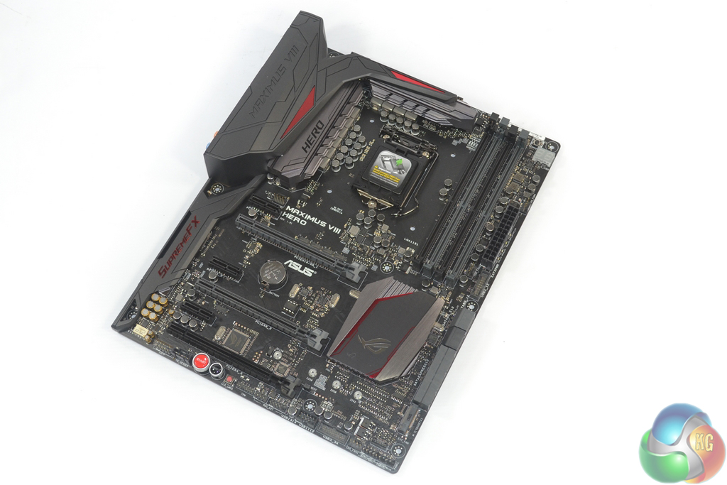
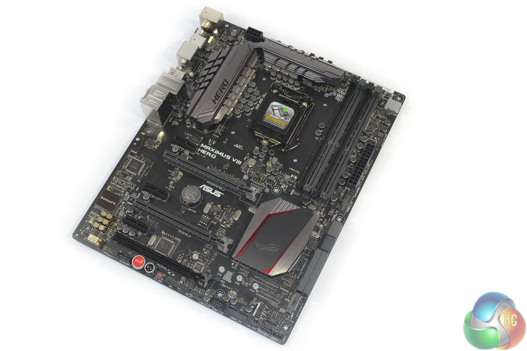
In a noticeable change from previous generation ROG products, Asus equips the Maximus VIII Hero with a largely black and grey colour scheme that sports tints of red. Asus is most likely of the mindset that red and black is becoming an overused colour scheme for motherboard and that something different, but not too far from past successes, should be attempted.
As is to be expected by any motherboard aiming for aesthetic wins, a matte black PCB is used throughout. Making use of a motherboard component that is becoming increasingly popular, Asus equips a plastic covering to block ugly reflections from the rear IO ports. The plastic shield also provides Asus with additional surface area that can be branded and styled to fit the ROG bill.
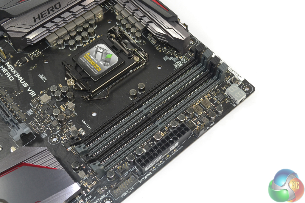
Four single-latch DIMM slots provide support for up to 64GB of dual-channel DDR4 memory. Asus quotes frequency support of up to 3733MHz, although higher memory frequency dividers are accessible in the UEFI. DDR3L memory is not supported by this motherboard. Close to the 24-pin connector is an outwards-facing USB 3.0 header. The upper-right corner is also the location for a two-digit debug LED.
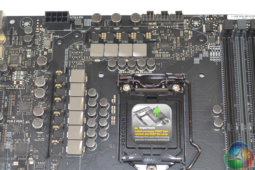
Feeding an LGA 1151 CPU are eight power phases that form Asus' Extreme Engine Digi+. A further two phases are used to drive the CPU's integrated GPU, while a separate pair is allocated memory powering duties. The Extreme Engine Digi+ power delivery components include 10K-rated black metallic capacitors, MicroFine alloy chokes which have a higher density through using a finer powder processing techniques, and NexFET MOSFET packages. All of this is managed by a digital PWM controller.
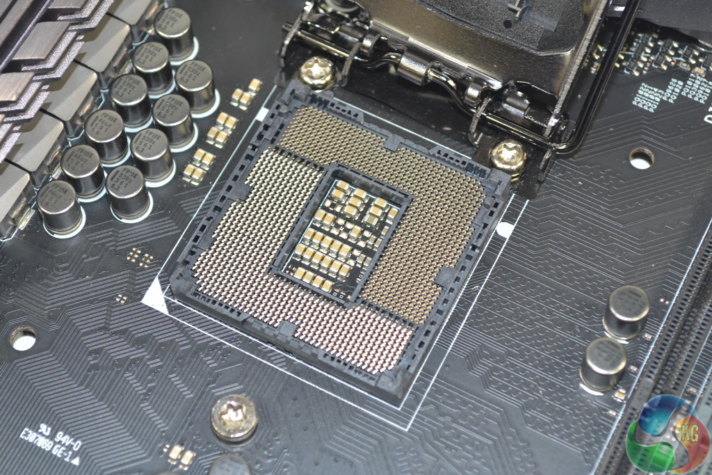
While there has been reference towards an enhanced OC socket design for Asus LGA 1151 motherboards, this is only applicable for the highest-end Deluxe and Maximus VIII Extreme SKUs. The Maximus VIII Hero does not feature a CPU socket that is any different to Intel's reference design.
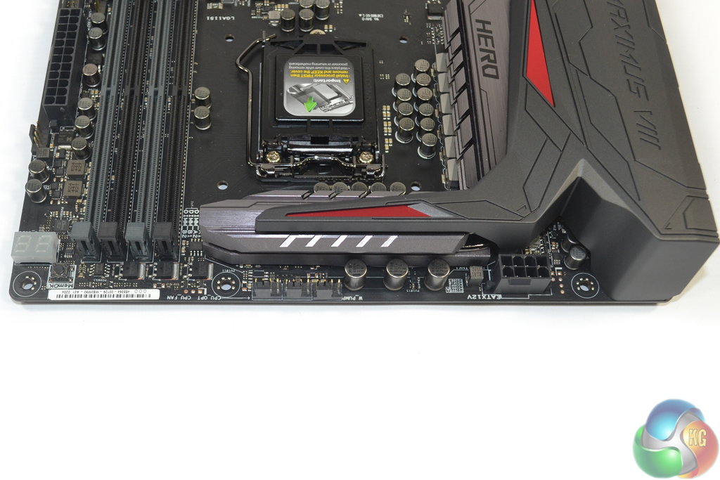
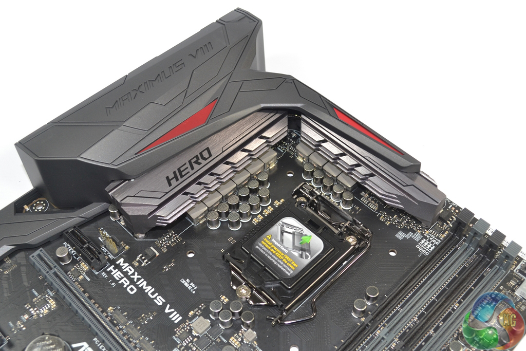
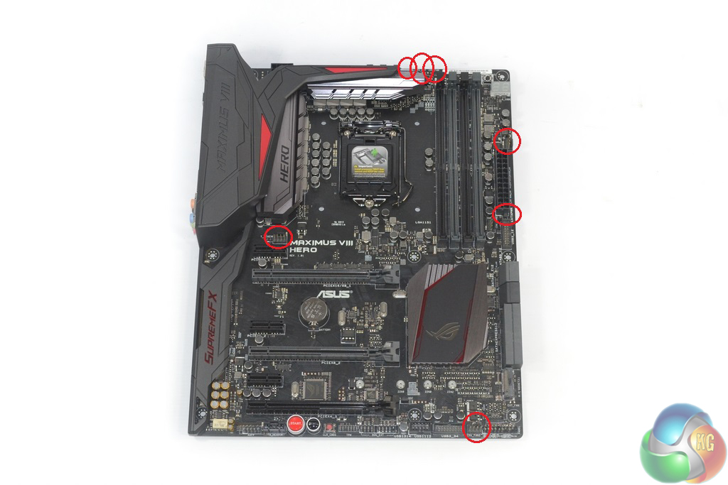
Along the motherboard's upper edge, nestled closely to the VRM heatsink are the 8-pin power connector and three fan headers.
Two of the 4-pin fan headers are allocated CPU fan duties, while the third is designed to be used with pump units for AIO water coolers. Asus decided to allocate a completely separate fan header that is intended to run at 100% speed so that users can avoid confusion when plugging in their AIO liquid cooler's pump. And if you don't require the header for a pump unit, it can be treated as a generic fan header and controlled through the UEFI.
I like this move because it makes the system building process less confusing for inexperienced builders. And even to those who understand how their AIO liquid cooler's pump functions, having a trio of fan headers in close proximity makes for easier cable management.
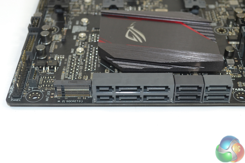
A total of six SATA 6Gbps ports are provided by the Z170 chipset, four of which can be used to double up as two 10Gbps SATA-Express connectors. An additional two SATA 6Gbps ports are provided by ASMedia' ASM1061 chipset. These connections are slower than the ones operating from Intel's chipset and should be reserved for slower storage devices.
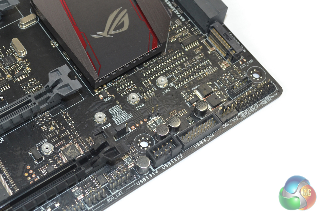
In the motherboard's bottom-right corner is the M.2 connector. Asus routes four PCIe 3.0 lanes to the slot in order to provide a bandwidth capacity of 32Gbps – an ideal number for fast drives such as Intel's SSD 750 and Samsung's SM951. M.2 drives up to 110mm-long are supported, as are adapter cards to provide a U.2 connector although these are likely to interfere with a graphics card in the second PCIe x16 slot.
M.2 SATA drives are also supported by the M.2 connector thanks to Intel's flexible IO lanes and their ability to switch between PCIe and SATA modes.
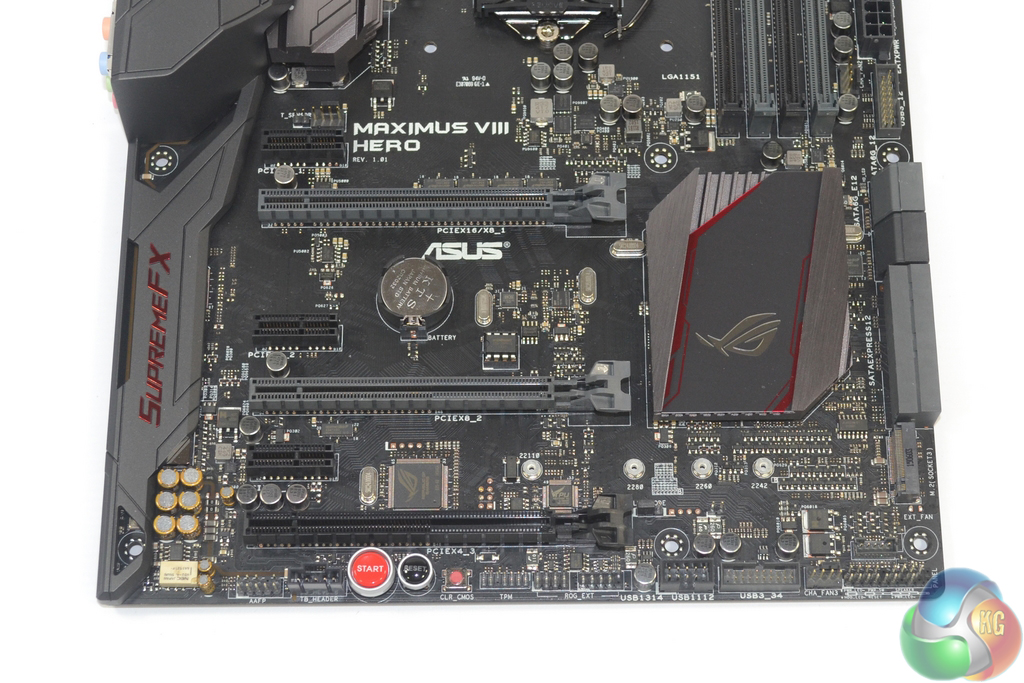
The uppermost pair of full-length PCIe 3.0 slots (the grey-coloured ones) receive their lanes directly from the LGA 1151 CPU, so these are the ones that you will want to use for graphics cards or high-speed PCIe storage devices. x16/x0 and x8/x8 operation is supported, making 2-card SLI and CrossFire possible.
The lowermost full-length PCIe slot siphons four PCIe 3.0 lanes from the Z170 chipset's plentiful stack. Thanks to the Z170 chipset's healthy allocation of PCIe 3.0 lanes, this connector can be used simultaneously with a PCIe 3.0 x4 SSD in the M.2 slot. There's nothing preventing the PCIe 3.0 x4-capable slot from housing an AMD GPU for a triple-card configuration, but the latency penalty would likely be significant.
A more sensible usage for the slot is as a home for PCIe SSDs such as the PCIe 3.0 x4 NVMe Intel SSD 750 drive. While this induces higher latency than the CPU-fed PCIe lanes, it also leaves those available exclusively to graphics cards. Two of the three open-ended PCIe 3.0 x1 connectors share bandwidth with the lowermost expansion slot and will force it into PCIe 3.0 x2 operation if all slots are utilised.
With Intel's latest RST drivers touting support for RAID of PCIe SSDs, I see no reason as to why one PCIe and one M.2/U.2 form factor (via an adapter) SSDs could not be installed and work together in RAID. They are both connecting via PCIe lanes to the chipset, and it's that connection method that is important, not the form factor that the drive occupies.
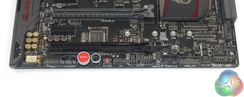
We find the usual USB, front panel, and audio connectors along the board's bottom edge. There's also an additional USB 3.0 header, power and reset buttons, a clear CMOS button, the Thunderbolt header, and a connector for the ROG OC panel.
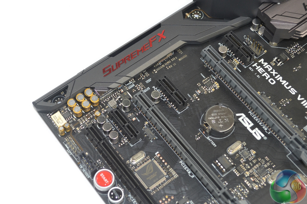
Audio is one of the areas where Asus invest heavily in the Maximus VIII Hero. Based around the Realtek ALC 1150 codec, Asus adds an ESS ES9023P DAC, A Texas Instruments R4580 amplifier, an NEC UD2-4 5NU de-pop relay, Nichicon audio capacitors, a dedicated clock, and a cluster of EMI prevention methods.
To compliment that audio hardware, Asus provides a comprehensive software tool to give audio control to the motherboard's users.
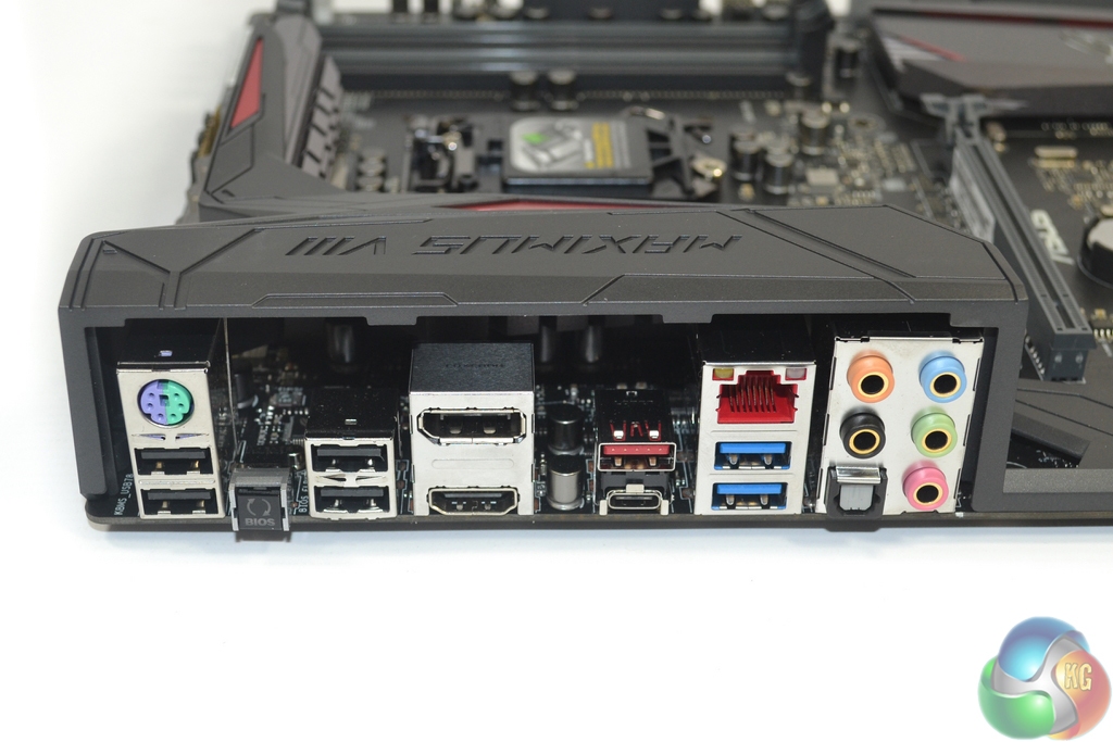
Four legacy USB 2.0 ports and the venerable PS/2 connector are retained for peripheral and BIOS flashing duties. Asus also outfits a pair of USB 3.0 Type-A ports stemming from the Z170 chipset, as well as a single 10Gbps USB 3.1 Type-A and one 10Gbps USB 3.1 Type-C connector which are provided by ASMedia ASM1142 and Etrontech EJ179V chipsets.
Gigabit Ethernet is provided by means of Intel's I219V NIC and Asus' own GameFirstIII network control software. The standard affair of audio connections is present. A 4K resolution at 60Hz is supported by the onboard DisplayPort connector, while the HDMI plug also support 4K but at a 24Hz refresh rate.
Asus' BIOS Flashback button can be used to flash the BIOS without hardware installed. It also serves as a convenient clear CMOS mimicking tool.
Distribution of the seven 4-pin fan headers is excellent. With the aid of Nuvoton's NCT6793D chipset, Asus allows these headers to be controlled via the UEFI or through a tool in its OS-based AI Suite 3 software.
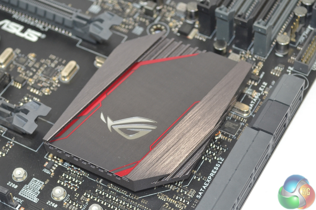
A practically limitless choice of colours can be selected for the chipset lighting feature. Users who want a stroke of yellow to contrast their black and red motherboard can apply that scheme. The lighting glows from beneath the chipset heatsink.
The plastic cover can be easily taken away by removing a handful of screws. Removing the cover reveals a sizeable pair of MOSFET heatsinks that are linked via a heatpipe.
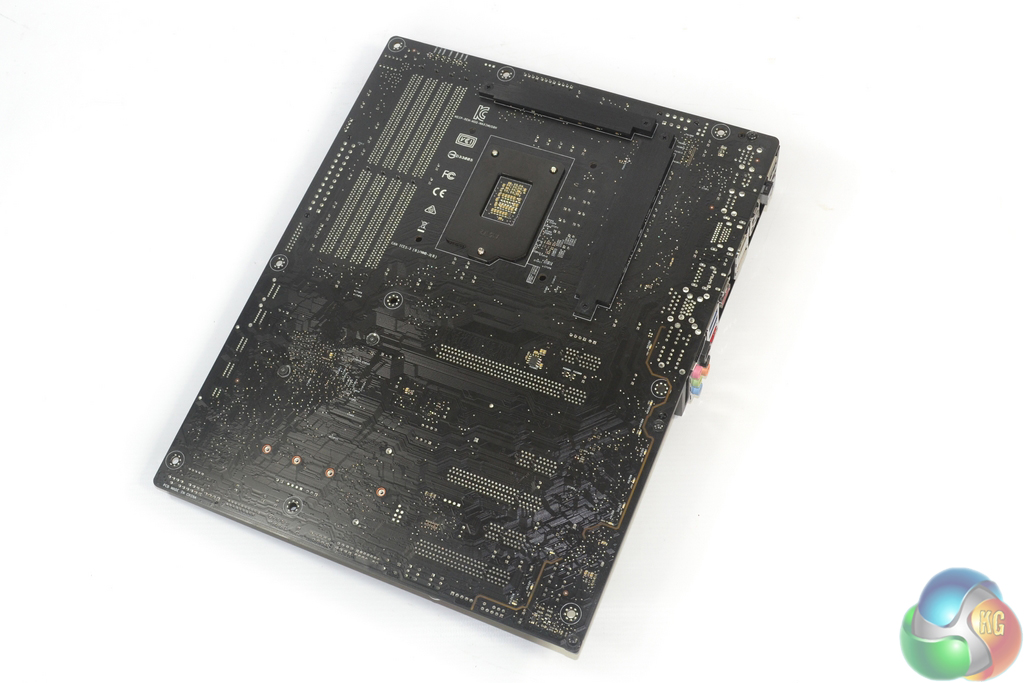
Two metal strips on the motherboard's rear side cool voltage regulation hardware that is mounted behind the board.
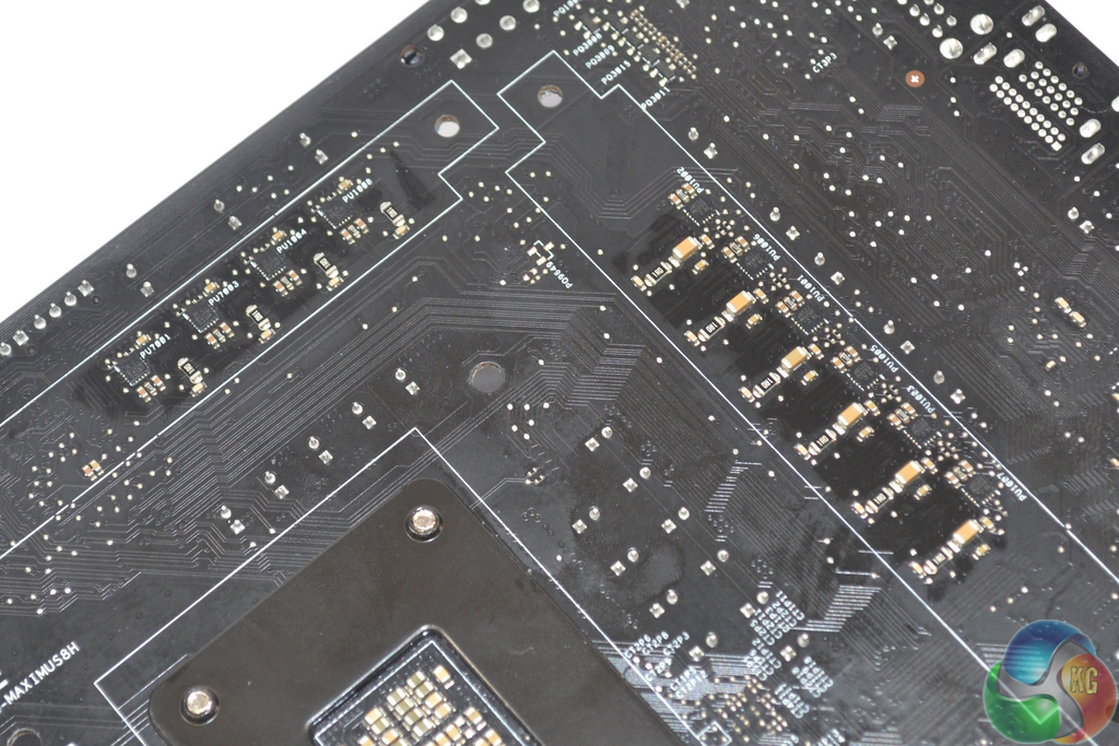
The Maximus VIII Hero's ten-phase power delivery solution relies upon Texas Instruments 87350D MOSFET power blocks which are rated up to 40A operation. The chokes do not seem to be of Asus' 60A BlackWing variety, so I would assume that the ones employed here sport a lower operating current level that matches the MOSFETs' limits.
While Asus' Digi+ VRM EPU ASP14051 controller is used to manage the power delivery system, the TI power blocks are driven by ten rear-mounted International Rectifiers IR3535M MOSFETs drivers. A Digi+ ASP1103 controller manages the DRAM power delivery system, while an IDT 6V41538NLC clock gen is used for fine BCLK adjustments.