

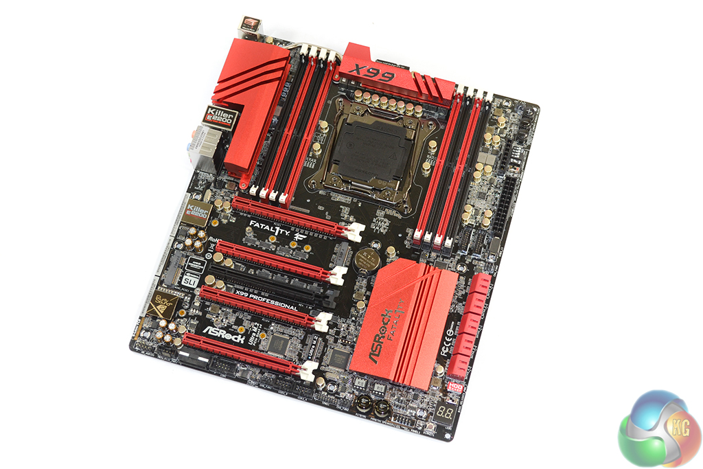
The ASRock Fatal1ty X99 Professional uses the typical red and black colour scheme that is associated with the series. While recent feedback from readers may suggest that red and black themes are beginning to bore them, old habits die hard. A black PCB is almost a necessity on the calibre of gaming board, so I am happy to report that ASRock has complied.
ASRock widens the motherboard’s PCB to the E-ATX form factor in order to fit the necessary hardware. This shouldn’t cause clearance issues for enthusiast cases, which are likely to support the extended PCB.
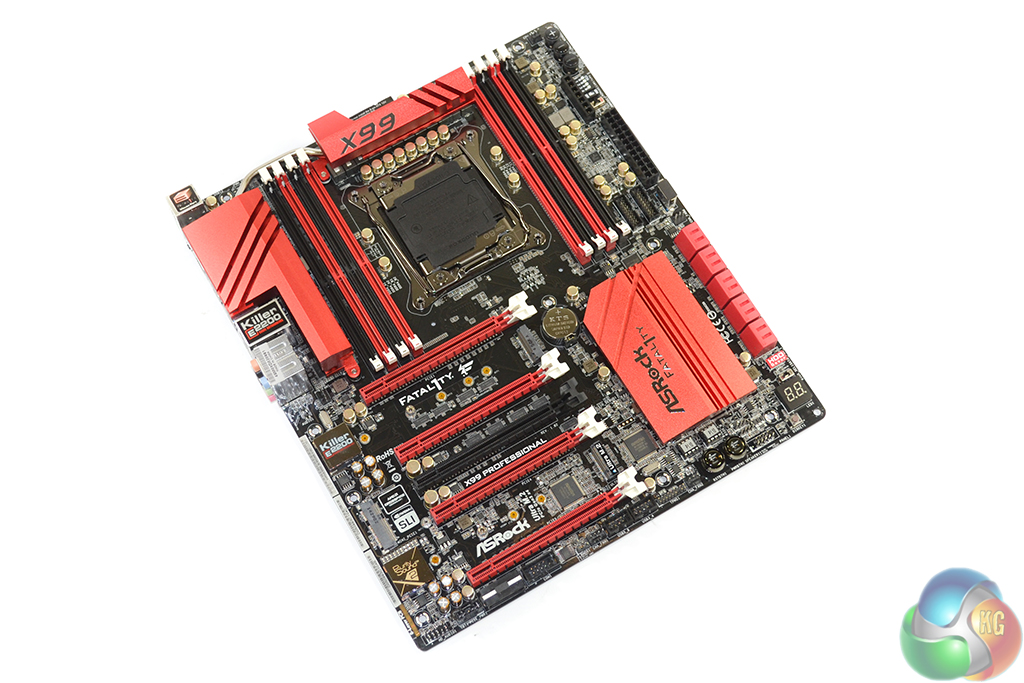
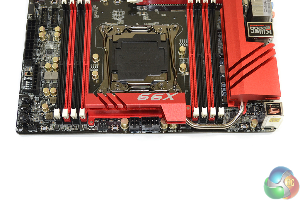
“XXL Aluminium Alloy” VRM and chipset heatsinks engulf a sizeable portion of the motherboard. While oversized heatsinks can sometimes act as an inconvenience, their implementation on X99’s hard-pushed VRM is welcomed.
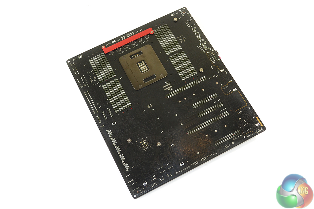
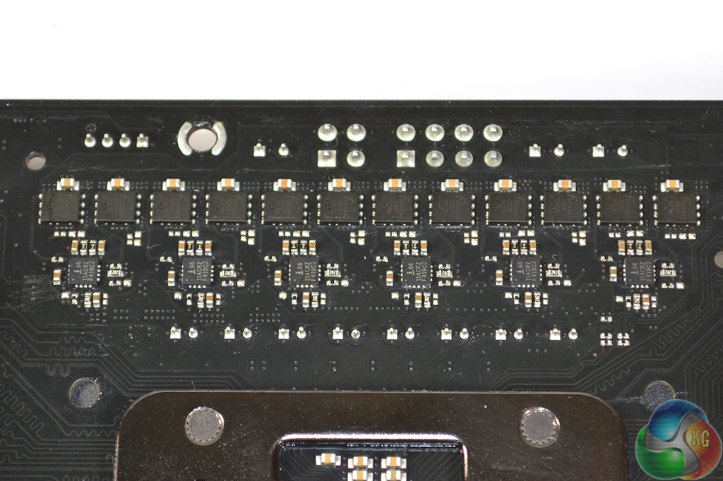
A smaller strip heatsink cools an additional 12 MOSFETs mounted on the motherboard’s rear side.
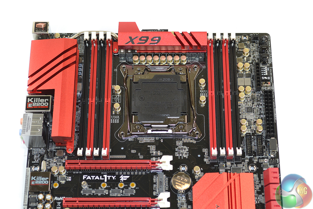
Sandwiched between a pair of DDR4 DIMM banks is the large LGA 2011-3 CPU socket. ASRock quotes support for memory frequencies above 3400MHz, although reaching those speeds will depend upon the BIOS implementation and the CPU’s IMC strength.
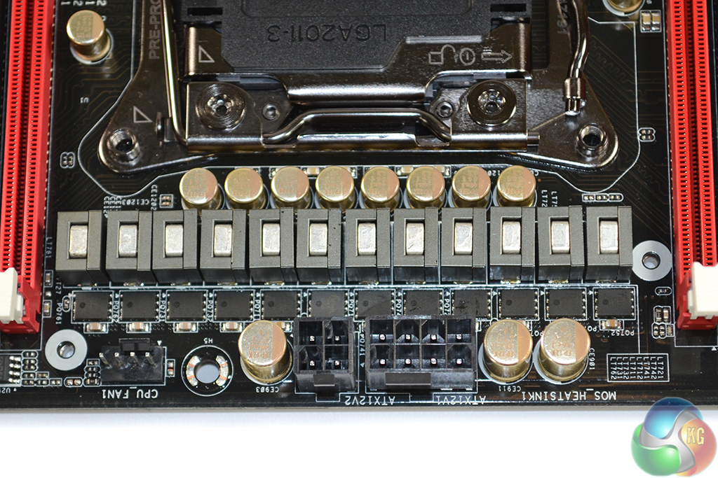
The power delivery system used by ASRock is generically similar across the company’s range of high-end X99 motherboards. Proving that point, the Fatal1ty X99 Professional uses a twelve phase system to feed a power-hungry LGA 2011-3 CPU. We took an in-depth look at ASRock’s power delivery system on the X99 OC Formula, over here (which is, as far as I can tell, identical to the Fatal1ty X99 Professional's system).
ASRock suggests that the system is capable of delivering up to 1300W of power to the CPU. Some quick maths suggests that this would be using a core voltage of around 1.8V, based on the 720A capacity of twelve 60A chokes.
ASRock also uses Nichicon ‘Platinum’ capacitors, rated for 12,000 operating hours at 105°C, for power delivery functions. Scale that running temperature down to a realistic operating value and it translates into a very long operational lifespan for each capacitor.
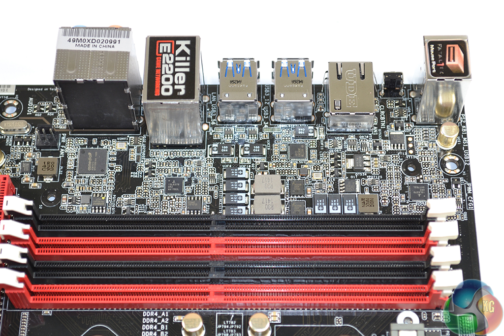
Two ISL6379 PWM controllers manage the X99 Professional’s two 2-phase memory power delivery systems (one power system for each DIMM bank). ASRock uses two Fairchild FDMS3660S MOSFETs per DIMM bank, as well as ‘Premium Memory Alloy Chokes‘ which are suggested to deliver their current with reduced temperatures.
Other memory-related components include (for each of the two systems/DIMM banks) Richtek's RT9045 regulator, two R30 1417 chokes, one R22 428 ZXA choke, one 1R0 430 C93 choke, and a mixture of capacitors.
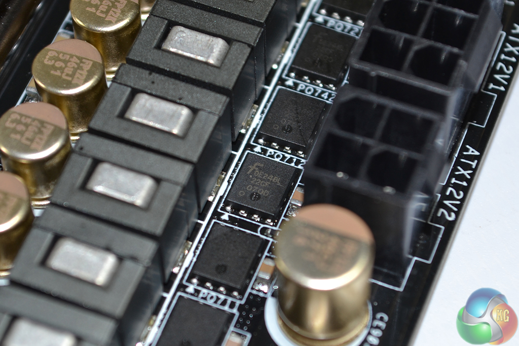
Looking more specifically at the CPU power delivery components, ASRock opts for a 6-phase Intersil ISL6379 PWM controller to provide the overall VRM management. Six Intersil ISL6611A phase-doublers each take a single PWM input lane from the ISL6379 and convert it to two PWM output lanes. This allows ASRock to provide twelve physical power delivery phases for the CPU.
Finding information for the ISL6379 PWM chip is very difficult, although numerous sources suggest that it is a ‘hybrid’ analog/digital controller. If that is indeed the case, it’s the analog section of the controller that is to thank for ASRock’s rapid voltage switching frequency which leads to positive power consumption numbers under low stock-clocked loads (as we will outline later). However, some of the enhanced accuracy and future-looking voltage level projection may be missing compared to a purely digital component.
A total of 24 MOSFETs are used to switch voltages, with twelve residing on the motherboard's front side and a further dozen on the rear. Marked with Fairchild Semiconductor's logo and DE24BL 22CF 070D text, these are the same FDMS3660S dual N-channel MOSFETs that we saw used on ASRock's X99 OC Formula motherboard.
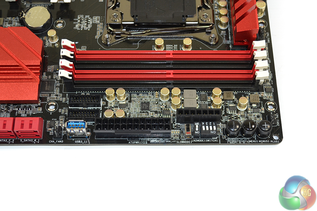
Situated in close proximity to the 24-pin power connector are two USB 3.0 headers. An ASM1074 hub controller is used to split one of the PCH USB 3.0 links in order to provide an outwards-facing standard USB 3.0 Type-A port.
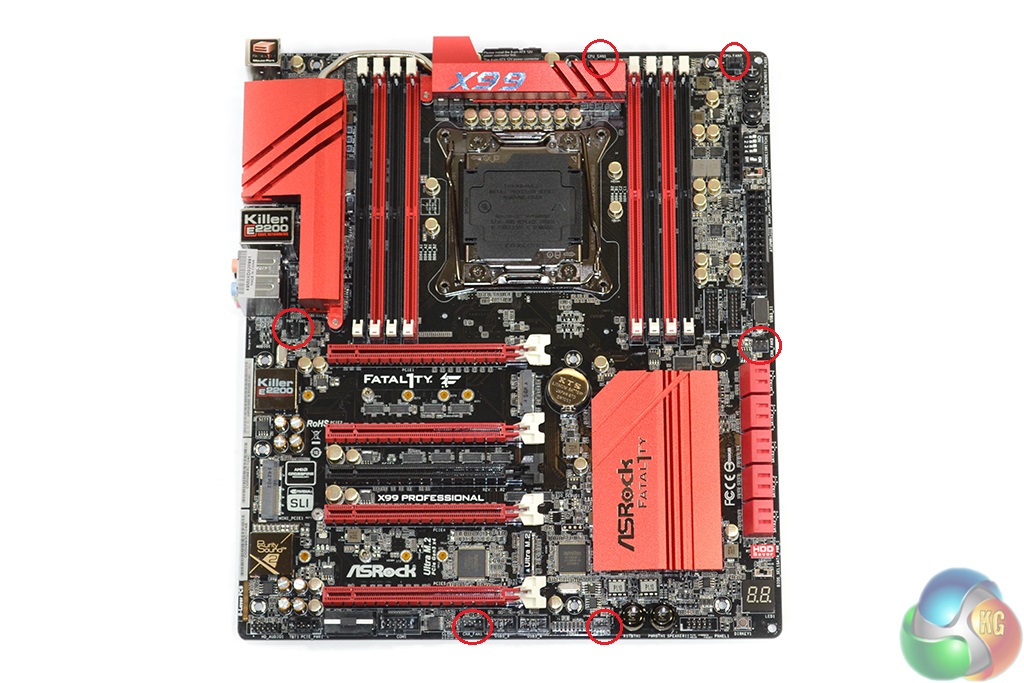
Voltage checking points, PCIe lane disabling switches, toggles for LN2 and slow mode operation, and onboard overclocking buttons spill over from ASRock’s overclocking-geared SKUs.
I like the inclusion of voltage checking headers and the PCIe lane disabling switch, although I don’t see the need for the other switches and buttons which are heavily geared towards sub-zero overclockers (which is not this board’s target audience).
An 8-pin CPU power connector is joined by a 4-pin slot in order to feed high currents to the hungry Haswell-E CPUs.
Although I do not believe that dual power connectors is necessary for a gaming motherboard, splitting the high currents demanded by a Haswell-E chip through two connectors may aid their longevity.
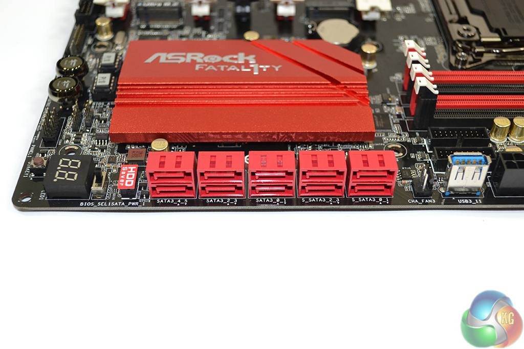
Ten SATA 6Gbps ports are all provided directly from the Intel X99 PCH. The six to the left should currently be used for RAID configurations, while the four on the right (labelled S_SATA_0-3) should be reserved for slower storage until Intel’s RST driver supports RAID on those ports.
Although we are still in the early stages of post-SATA-6Gbps storage interfaces, M.2 seems to have already prevailed as the primary solution for high-speed drive connections. For that reason, I do not see the lack of SATA Express as a glaring negative; there are the M.2 connectors to rely upon for high-speed SSD-based storage, while SATA 6Gbps proves adequate for slower HDDs.
ASRock’s HDD Saver port can be used to power up to two drives. The function is useful if you want to control your drive’s operating state via the OS – perhaps for security, noise, or longevity purposes.
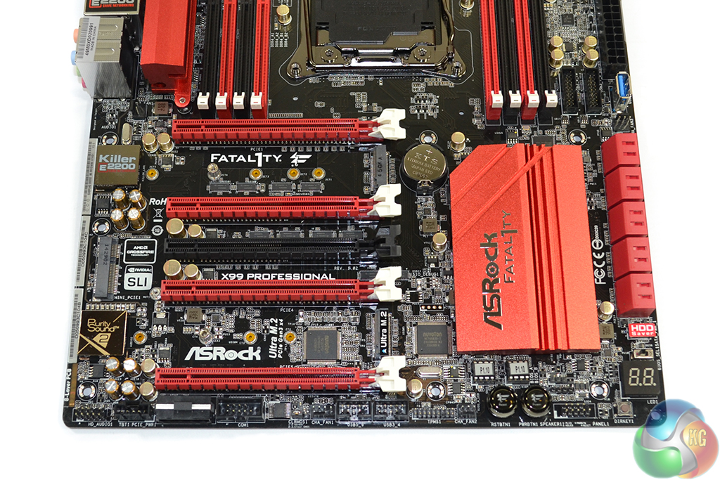
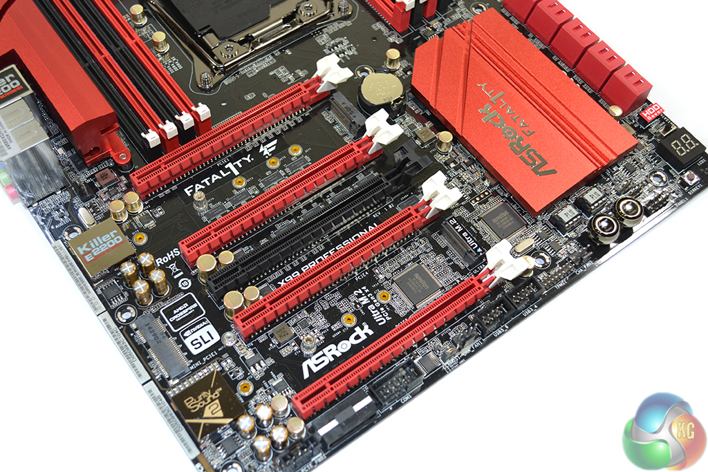
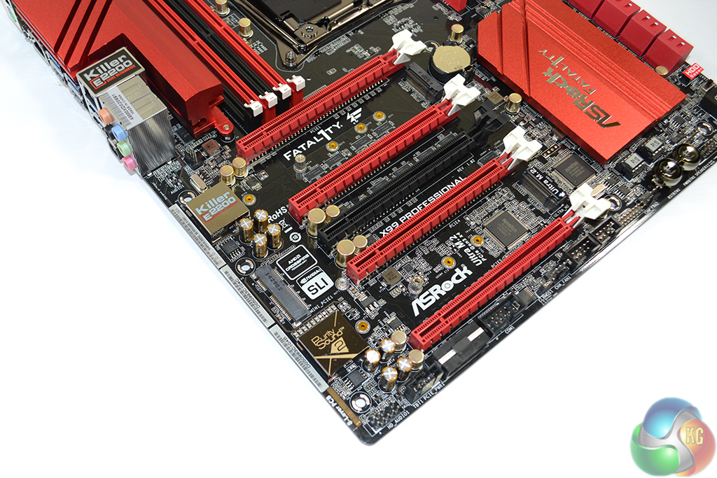
High-bandwidth 4-way SLI and CrossFire are both supported by the X99 Professional, provided a 40-lane CPU is used. The red slots are to be used for graphics cards, the first and third of which are hard-wired for up to sixteen PCIe lanes, with the other two linking by a maximum of eight lanes.
The uppermost (PCIE1) PCIe slot is used for a full x16 link to one card, while two cards are given sixteen lanes each, as well as two cooling gaps, using the PCIE1 and PCIE4 connectors. Three cards rely upon the first three red connectors, and are linked to the CPU at PCIe 3.0 x8/x8/x16. 4-way configurations use all of the red PCIe connectors in an x8/x8/x8/x8 link.
With a 28-lane CPU, the lowest PCIe slot is disabled and the remaining PCIe links are x16/x0/x4/x8 or x8/x8/x4/x8. So back-to-back triple-card configurations are inevitable with a 40- or 28-lane CPU. But two-card spacing is excellent.
The black connector can be thought of as an expansion card slot (for the likes of high-bandwidth PCIe SSDs or RAID cards); the connector runs at a maximum of PCIe 3.0 x4 and steals its bandwidth from the PCIe 3.0 x4 Ultra M.2 slot.
I have no problems with ASRock’s PCIe configuration; the layout is smart and 4-way SLI/CrossFire can be used alongside a PCIe 3.0 x4 SSD in the Ultra M.2 slot.
Aiming to provide further upgrade potential, ASRock equips the Fatal1ty X99 Professional with not one, but two M.2 connectors. Both slots support the common 2242, 2260, and 2280 form factors, as well as the 110mm-long 22110 implementation. Hardware RAID is not supported between the two connectors due to one connection deriving from the chipset and the other from the CPU.
The uppermost slot receives up to four PCIe 2.0 lanes from the X99 PCH, giving it a bandwidth of 20Gbps which is ideal for serving fast M.2 SSDs, such as Samsung’s XP941. M.2 SATA drives are also supported on the uppermost slot, although this renders the S_SATA_3 port inactive.
ASRock’s Ultra M.2 moniker is given to the lower M.2 connector, indicting its usage of four PCIe 3.0 lanes from the CPU for up to 32Gbps bandwidth potential. This 32Gbps M.2 port can still be used alongside 3-way graphics setups on a 28-lane CPU and 4-way on a 40-lane chip.
A half mini-PCIe slot uses a single PCIe 2.0 lane from the X99 PCH. Its inclusion is convenient for users who want internal WiFi but cannot afford to sacrifice an expansion slot from a high-bandwidth PCIe device or graphics card.
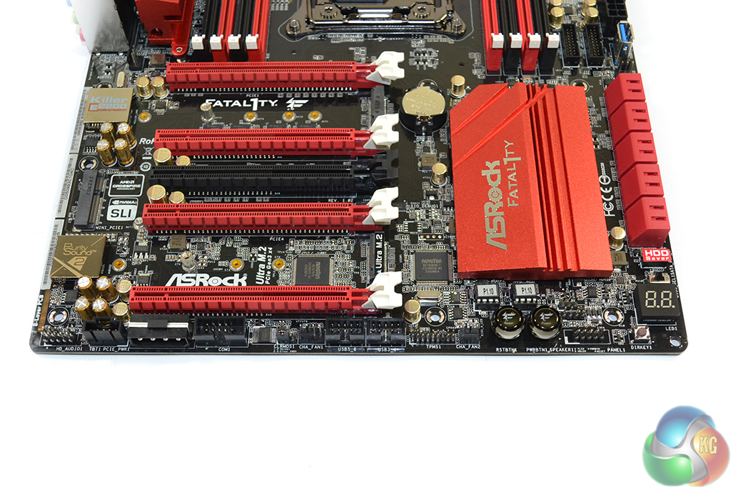
Bottom edge connectors are the standard affair – audio to the left and front panel connector to the right. Two USB 2.0 headers feature, as well as a synchronisation link for add-in Thunderbolt II cards. ASRock includes a downwards-facing molex power connector to stealthily provide additional juice for taxing multi graphics card setups.
Onboard power and reset buttons are convenient when troubleshooting, while the DirectKey button is useful for booting straight into the BIOS. The onboard debug LED is equally convenient for rapid troubleshooting measures.
That said, all of those ports should be placed on the upper-right corner of the board where they are always accessible. Users of this board are far more likely to require access to the power and DirectKey buttons than the finesse overclocking toggles.
I like ASRock’s inclusion of two BIOS chips and the linked toggle switch – it gives the board redundancy in the event of a BIOS corruption. Other notable connectors are COM and TPM headers, a clear CMOS jumper, and two chassis fan headers.
ASRock’s Purity Sound 2 audio system is based around the Realtek ALC1150 codec. Nichicon Fine Gold series capacitors smooth the audio signal while a pair of Texas Instruments NE5532 amplifiers cater for high impedance headphones to both the front and rear IO ports.
A dedicated cover for the codec and a segregated audio path aim to minimise the level of EMI. ASRock does not use gold-plated jacks on the rear IO, however.
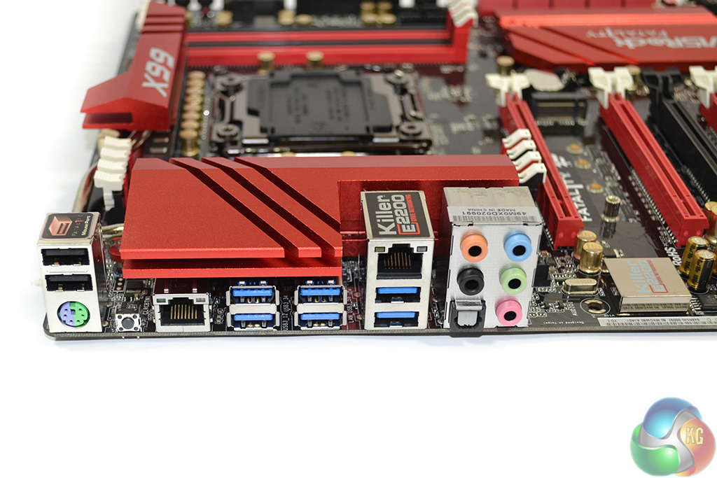
Six USB 3.0 ports are found on the rear IO, four of which are duplicated by an ASMedia ASM1074 hub controller. Two USB 2.0 ports are ideal for low-bandwidth peripherals, with one of the connectors supporting ASRock's Fatal1ty Mouse Port. PS/2 is provided for legacy support.
Intel's I218-V chipset provides one of the GbE connections, while the other is controlled by a Killer E2200 series NIC. I like this move by ASRock because I know that many enthusiasts detest Killer NICs, while others may prefer its OS-based network management software.
Audio connectors and a clear CMOS button (which I absolutely love to see included) complete the rear IO.
Distribution of the board's six fan headers (four 3-pin, two 4-pin) is excellent. Two headers cater for CPU fans, although I would have liked to see easier access to a third – powered – connector for AIO liquid coolers' pump units. Placing three headers on the board's edges is great for cable management purposes, while the cable path for a rear chassis fan is minimal.
ASRock employs two Nuvoton SuperIO chipsets – the NCT6791D and NCT6683D-T. While they can both perform the same voltage, temperature, and fan speed monitoring functions, I’d wager that the more advanced NCT6683D-T is included for its enhanced fan control and SPI flash capabilities.
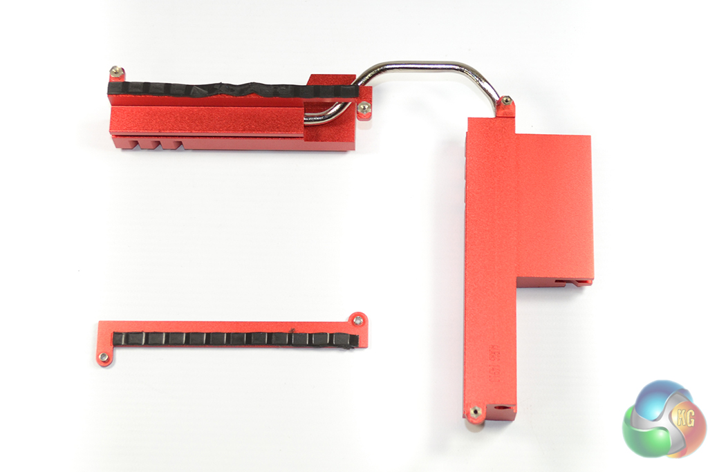
The sizeable pair of aluminium alloy heatsinks are easy to remove from the motherboard. Although technically analysing their performance is very difficult, the heatsinks' sheer bulk makes them seem sufficient for cooling the motherboard VRM.
Its quite controversial for a company linked to overworked employees suicides to name their product Fatality…
♪♪get $73 every /hr@ac23:
Going Here you
Can Find Out,
►►► http://CareerMaxJobs91.biz/live/trades/onlines…
You guys make some weird choices. You have trouble using the 2666MMhz g.skill memory and opted to use memory from Corsair, but later in the review you say that the 3000Mhz G.Skill memory was performing fine. So why not do the main tests with the 3000Mhz memory instead of 2666Mhz memory from another manufacturer. It seems to me that the 3000Mhz and 2666Mhz memory modules of G.Skill are closer to each other than 2666Mhz memory from different manufacturers..
so what’s better for gaming the z170 or the x99