
MSI MPG X570 Gaming Edge WiFi
MSI’s MPG X570 Gaming Edge Wi-Fi uses an eight-phase CPU power delivery system, just like ASRock. However, it is the only board in our comparison that opts for the cheaper On Semi discrete MOSFETs rather than Vishay DrMOS power stages.
As already mentioned, we had issues trying to get the wall power draw from the MSI board to comparable levels when overclocked. As such, our wall power draw for the MSI competitor was 250-265W, though it generally stayed between 250-260W.
Another challenge with testing the MSI board is that our thermocouples were experiencing significantly higher levels of EMI than with the competing solutions. This forced us to use a tactic of quickly killing system power directly after heavy load in order to record the MOSFET temperatures without EMI.
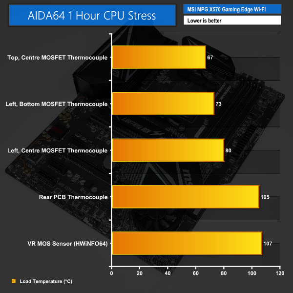
We recorded a maximum temperature of 80°C with our thermocouple mounted on the left-side, centre MOSFETs. One challenge with this reading was that our thermocouple could sometimes bridge across the high- and low-side MOSFETs as this board was particularly difficult when installing the thermocouples. Nevertheless, 80°C reading from our thermocouple is undeniably high.
Interestingly, the left-side, bottom MOSFET actually ran around 7°C cooler at 73°C. The top-side MOSFET also ran cooler at 67°C, when normalised to 25°C ambient. The difference in recorded temperature between the centre and bottom MOSFETs on the left side of the CPU socket implies that the centre one is having difficulty in shedding its heat.
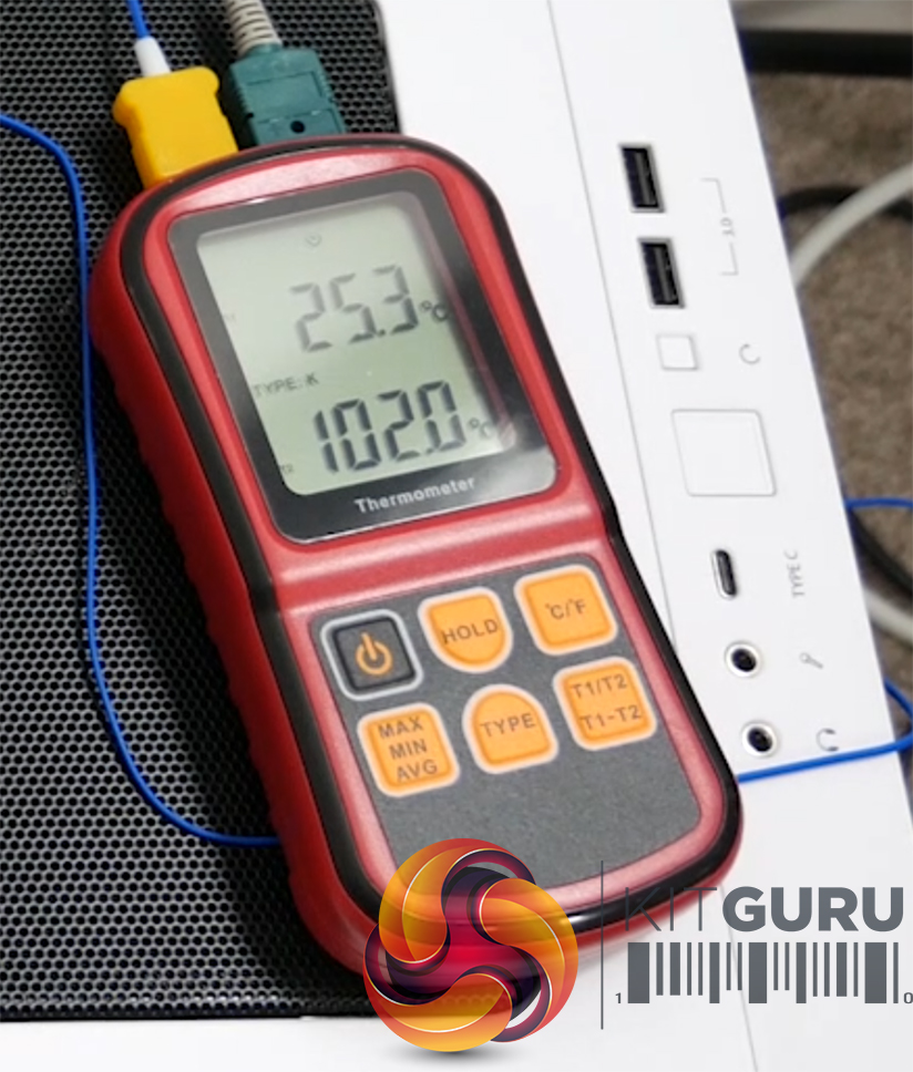
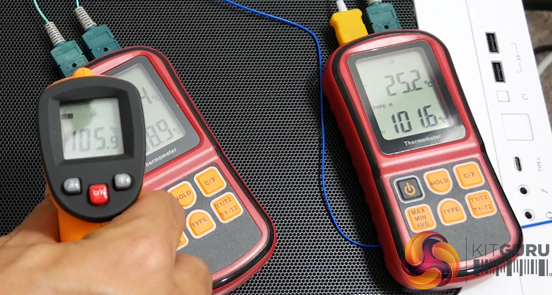
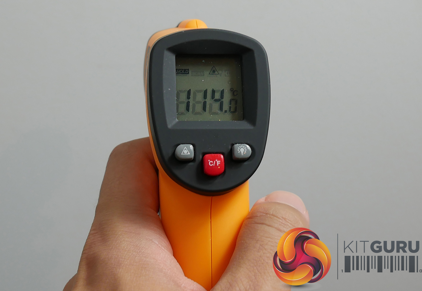
It doesn’t take us long to find the source of that difficulty in shedding heat – the PCB temperature. Topping out at more than 105°C on our thermocouple (we actually read as high as 114°C in certain spots with the laser thermometer), the PCB temperature anywhere near the MOSFETs was ridiculous. We wanted to make sure these alarming readings were correct, so an additional thermocouple was mounted on the front side PCB, to the right of the inductors. Its reading was 100°C also, so we were confident in the results.
To say that a PCB temperature of more than 100°C is alarming is an understatement. With this temperature level, I would not feel comfortable running this kind of workload on a frequent basis. Also bear in mind that there was no GPU, M.2 SSD, or X570 chipset load dumping additional heat into the motherboard PCB.
Checking the sensors from the IR PWM controller and a Nuvoton monitoring chipset in HWiNFO64 highlighted readings of just under 110°C in both cases. While the MOSFETs may technically be able to operate at these temperatures, the levels certainly aren’t good for longevity or peace of mind (which is important when building a system).
Considering that running temperatures over 100°C were highlighted by the International Rectifiers and Nuvoton sensors built into MSI’s motherboard, in addition to our own PCB readings in several locations using a laser thermometer and K-type thermocouples, we’re more than happy to believe those. The difficulties that we had with EMI and correct mounting of our thermocouples on top of the MOSFETs imply that our recorded MOSFET temperatures are possibly lower than the actual temperatures.
MSI’s power delivery solution on this motherboard is not well equipped for handling an overclocked 12-core Ryzen part. That’s disappointing, especially when its competitors all fare so well.
At least the cooling rate from MSI’s massive heatsink was a positive – the MOSFETs and PCB dropped to around 50°C five minutes after the load was removed, and with no system airflow.