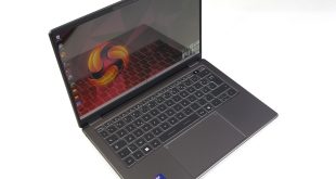
ASRock’s roughly £210 competitor comes in the form of the X570 Steel Legend. This motherboard features a unique and interesting design style, with camo-type patchwork on the PCB.
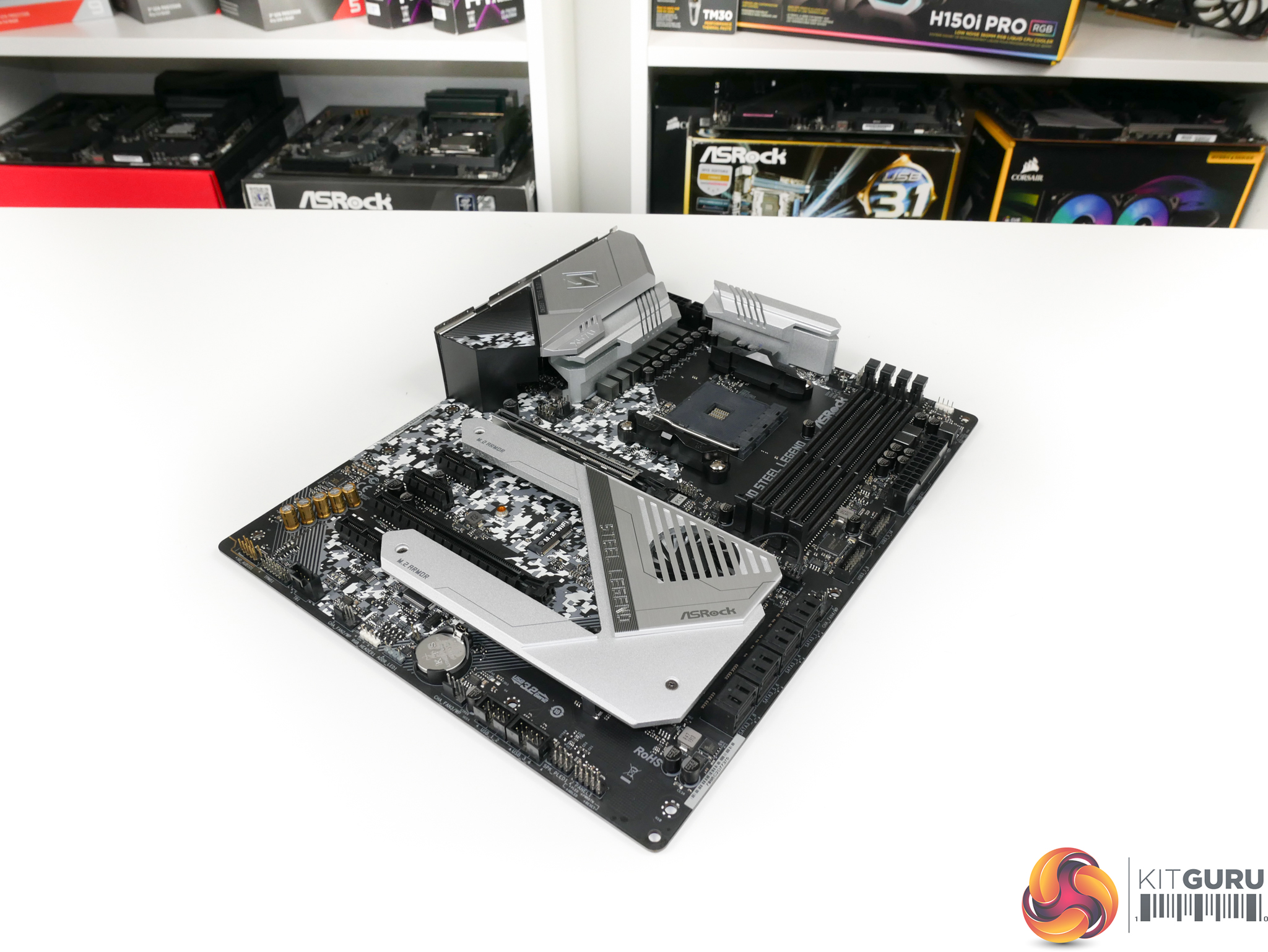
Focusing on the power delivery system, ASRock equips this motherboard with an 8+2 phase physical implementation.


ASRock is using an Intersil ISL69147 which is a dual output digital PWM controller that supports up to seven total control phases in an X+Y configuration. ASRock uses this capability, with the assistance of four ISL6617A phase doublers, all of which are mounted on the rear of the PCB in an un-cooled position.
The combination of ISL69147 PWM controller + four ISL6617 phase doublers gives ASRock’s X570 Steel Legend an electronic VRM system of 4×2 + 2. So, the CPU VCore VRM is made up of four doubled phases while the SoC VRM gets two dedicated phases without doublers.
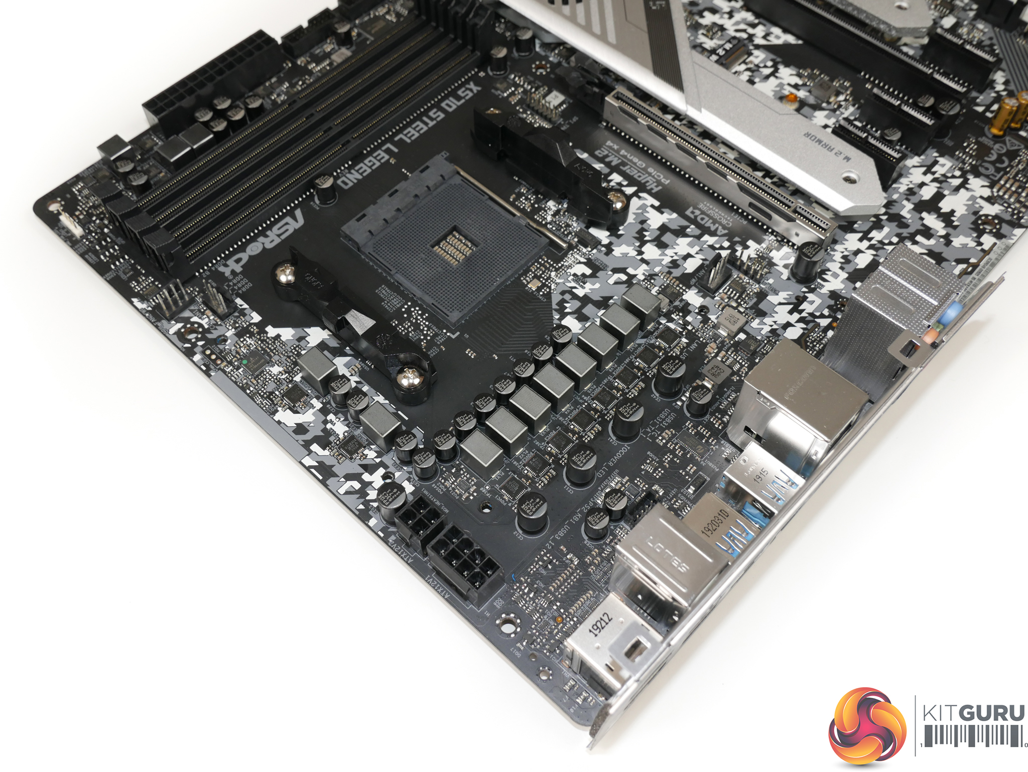
Focussing specifically on the 4×2-phase CPU VCore MOSFET solutions, ASRock is using eight Vishay SiC634 DrMOS power stages. These co-packaged power stages are advertised with a 50A current capability for continuous output, though they do support a 10% higher current load for 10ms bursts. These are the same solutions that we have seen on ASRock’s higher-end X570 Taichi motherboard.
Overall, they’re pretty decent units and I would not call them out of place on a £210 mainstream motherboard. Importantly, for this test, the integrated power stages look to have a solid thermal resistance rating which should help when trying to shed their electrical resistance heat.
The two-phase SoC VRM is handled by a pair of Vishay SiC632A integrated power stages. These look to effectively be de-rated SiC634 solutions, with many of the specification curves highlighting a 45A realistic limit. These should be perfectly adequate for pushing the SoC, even when an APU is used.

Worth noting briefly is ASRock’s use of 12K-rated capacitors in the CPU and SoC region. This is an improvement to longevity over the 5K-rated caps we’d typically see on motherboards trying to squeeze the budget for their respective platform. It’s quite important in this scenario too, as the nearby heat from the VRM and high core count CPU can drive up capacitor temps and push them closer to that 105C rating level where the printed number of hours (5,000 or 12,000, for example) is a genuine statistical reality for expected operating life.

In terms of MOSFET heatsinks, I’d say ASRock’s effort is pretty poor. The two discrete heatsinks are more of a fashion accessory rather than real heatsinks as they feature very little effort to increase their surface area. There are some cut-outs here and there and a through-channel does help to increase surface area a little, but there’s no real sign of fins or genuine good heatsink design practice. At least the mounting pressure is good thanks to the use of screw fittings, and ASRock doesn’t overdo the thermal pad thickness which is good to see.


To an extent, inefficient heatsink design can be counteracted by simple metal mass. ASRock hasn’t really applied this logic, either, with the top-side SoC heatsink weighing 61 grams and the left-side CPU VCore heatsink weighing 82 grams.
The distribution of heatsink weight is actually pretty important in ASRock’s design as all of the CPU VCore MOSFET heat will be dumped into the single 82 gram heatsink. Typically, we’d see the CPU VCore MOSFETs mounted to the left and to the top of the CPU socket, thus splitting their thermal load between heatsinks. That’s not the case on the X570 Steel Legend.
At least the height of ASRock’s heatsinks is somewhat positive. They’re not low-profile or flat, so it is likely that incidental airflow will at least interact with the metal, even if not significantly.
There’s no heatpipe connecting the two heatsinks to one another, or to other heat-producing components such as M.2 SSDs or the X570 chipset. That means that the small blocks of metal are simply tasked with handling cooling for their MOSFETs mounted beneath, and nothing else.

Finally, you get a supplementary 4-pin power connector partnering the 8-pin. That’s not really important for AM4 with a motherboard of this calibre.