
ASRock X570 Steel Legend
First up is ASRock with its doubled 8-phase CPU VCore VRM consisting of Vishay SiC634 DrMOS power stages.
Our overclocked settings resulted in 245-250W of wall power draw under AIDA64 load. Importantly, we saw no signs of VRM-induced frequency throttling, so that’s a good result to start with.
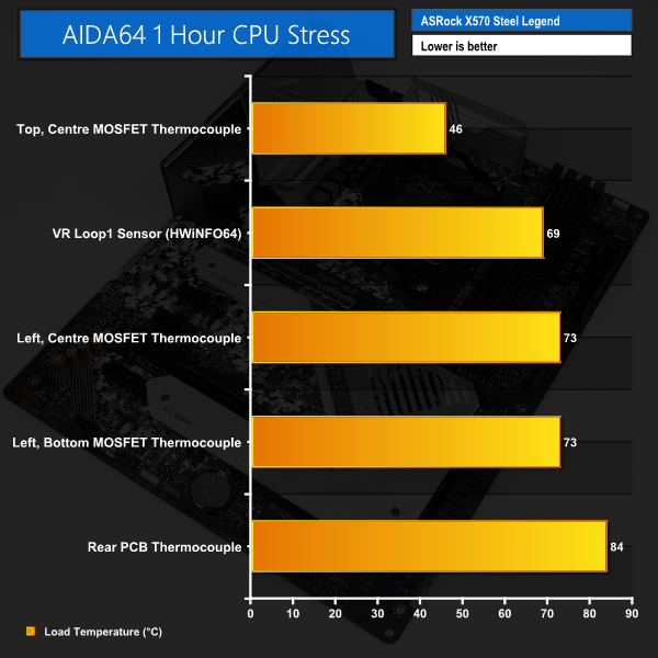
Looking at the MOSFET temperature performance, we saw a maximum temperature of 73°C, when normalised to 25°C ambient. This highest temperature reading was actually displayed on both the bottom- and middle-mounted power stages in ASRock’s configuration, which is a little surprising at first. It then becomes clear why the central power stage is operating at the same temperature as the end power stage – ASRock puts the entire bank of eight phases feeding the CPU to the left of the motherboard and underneath the single 82 gram heatsink. 1 hour is long enough to reach thermal steady state and the nearby MOSFETs operate at the same temperature.
73°C is hot but it is no real cause for concern. According to ASRock’s software-based sensor reading, the motherboard VR Loop1 sensor showed 69°C, so this reading is not too far away from our direct measurement, which is good.
Our thermocouple mounted on the top-side bank of MOSFETs above the AM4 socket highlighted that the SoC doesn’t get pushed particularly hard for CPU-only loads. The reading stayed below 50°C throughout testing. This does, however, highlight some degree of inefficiency with ASRock’s power delivery layout. Two of the eight CPU power phases could have been shifted to this region so that their heat load could be placed on the secondary heatsink. Perhaps this is not deemed an issue as the recorded temperature levels were fine anyway.
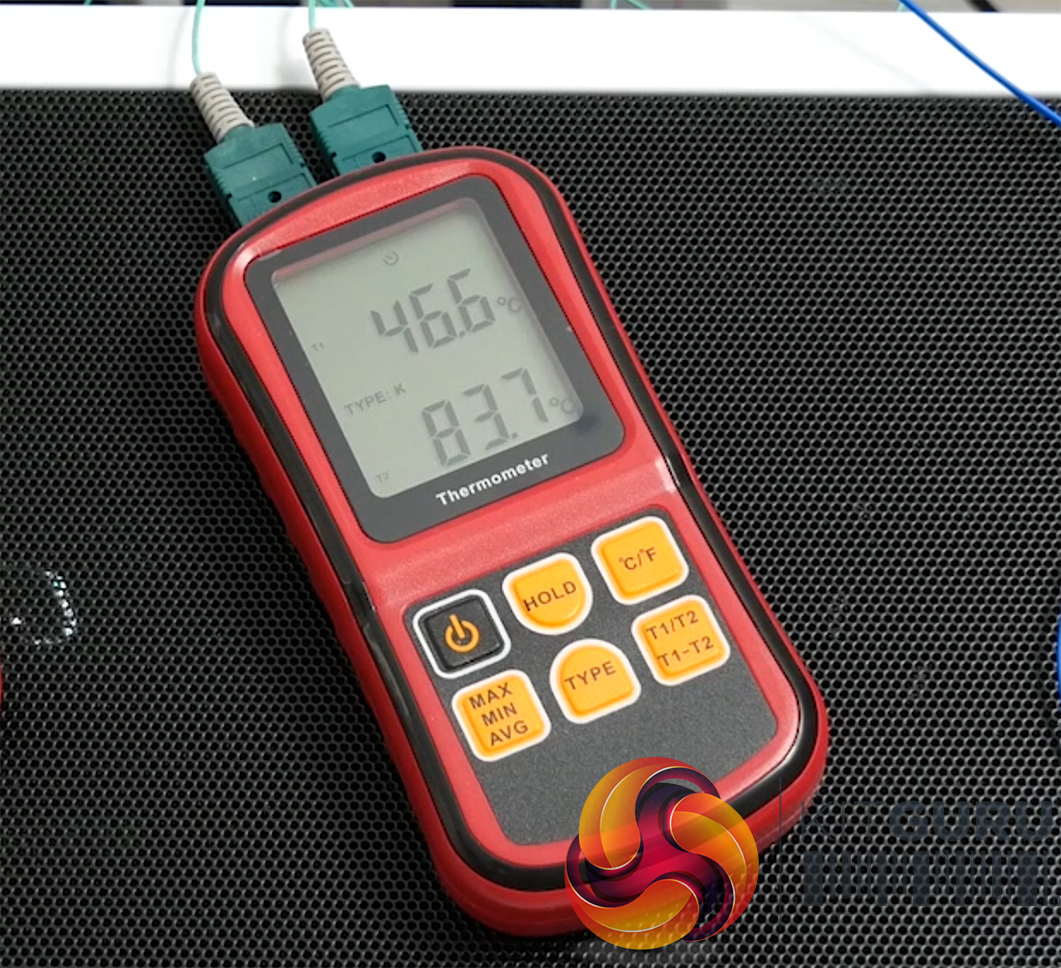
The rear PCB recorded temperature was high at just under 85°C. That’s pretty hot for a motherboard PCB. Clearly, a significant amount of thermal energy is soaking into the motherboard PCB rather than through the heatsink. A better heatsink design and more efficient physical distribution of the MOSFET power stages would have compensated for this.
We also noticed that the top side power stage temperature rose by a couple of degrees when the system was powered down and airflow was removed. This implies that heat from the PCB is soaking into the top VRM heatsink and causing a rise in MOSFET temperature, even if it is only for a few minutes before starting to cool again. Thankfully, the PCB temperature drops quite quickly once load is removed, however, that may not be the case if a heavy GPU or X570 chipset load has been applied in tandem.
After five minutes of the load being removed on system shut down, the CPU-side power stages cooled to just over 50°C while the PCB was just under 50°C. This is a decent cooling rate and shows that the heatsink can flush away its thermal load even if the system is shut down quickly after a heavy load.
Overall, we would say that there is no cause for concern from ASRock’s X570 Steel Legend. The relatively small heatsink does a decent enough job at dealing with the efficient 8-phase power delivery system. PCB temperatures are pretty high, but this did not result in instability or worrying temperature sensor readings. We saw no signs of instability at all throughout testing.