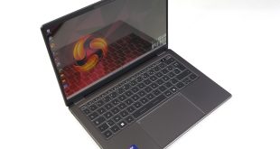

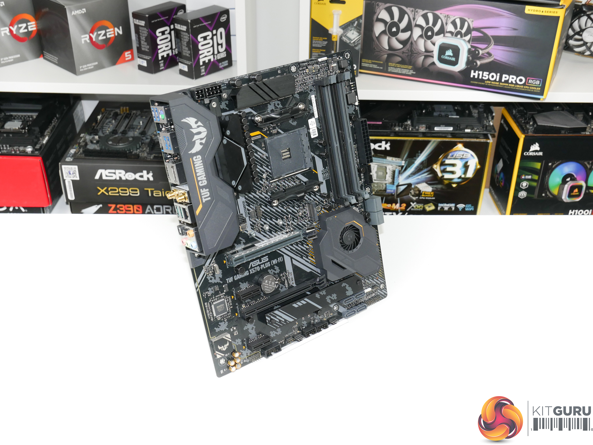
ASUS’ £210 competitor comes in the form of the TUF Gaming X570-Plus Wi-Fi – a name that is far, far too long! Technically, we have the £225 Wi-Fi version of this motherboard, but ignoring the wireless adapter makes it the £210 version. We checked with ASUS and they confirmed that there is no power delivery difference between the £225 Wi-Fi version and the £210 non-Wi-Fi alternative. So, we have no problem including this with our £210 competitors.
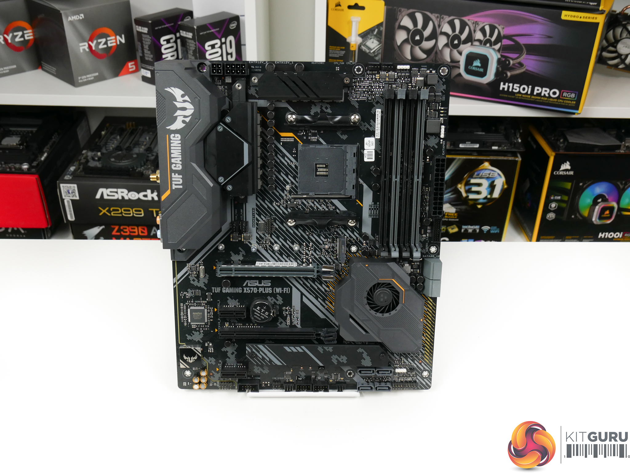
Here we see another motherboard that features camo-style design work on the PCB, in addition to ASUS’ usual yellow and grey accents for TUF series products.
Focusing on the power delivery solution, ASUS equips the TUF X570-Plus with a 12+2 phase physical implementation.
ASUS is using a proprietary ASP1106G PWM controller in a 4+2 phase mode. Details for this controller are limited but it is likely a re-badged Intersil PWM.
Interestingly, given the rather limited 4+2 electrical phase control capability of the PWM, we do not see ASUS applying any PWM phase doublers. This is typical of what we have seen from ASUS motherboards recently, with the vendor arguing that ‘fattening up’ the quantity of electrical components per phase signal is more beneficial than doubling the phases via a dedicated logic IC.
As such, ASUS’ 12 CPU VCore phases are actually a 4×3 design with three lots of electrical components per single control phase. You can see which phases are working together by decoding the text on the PCB highlighting power phase mounting positions.
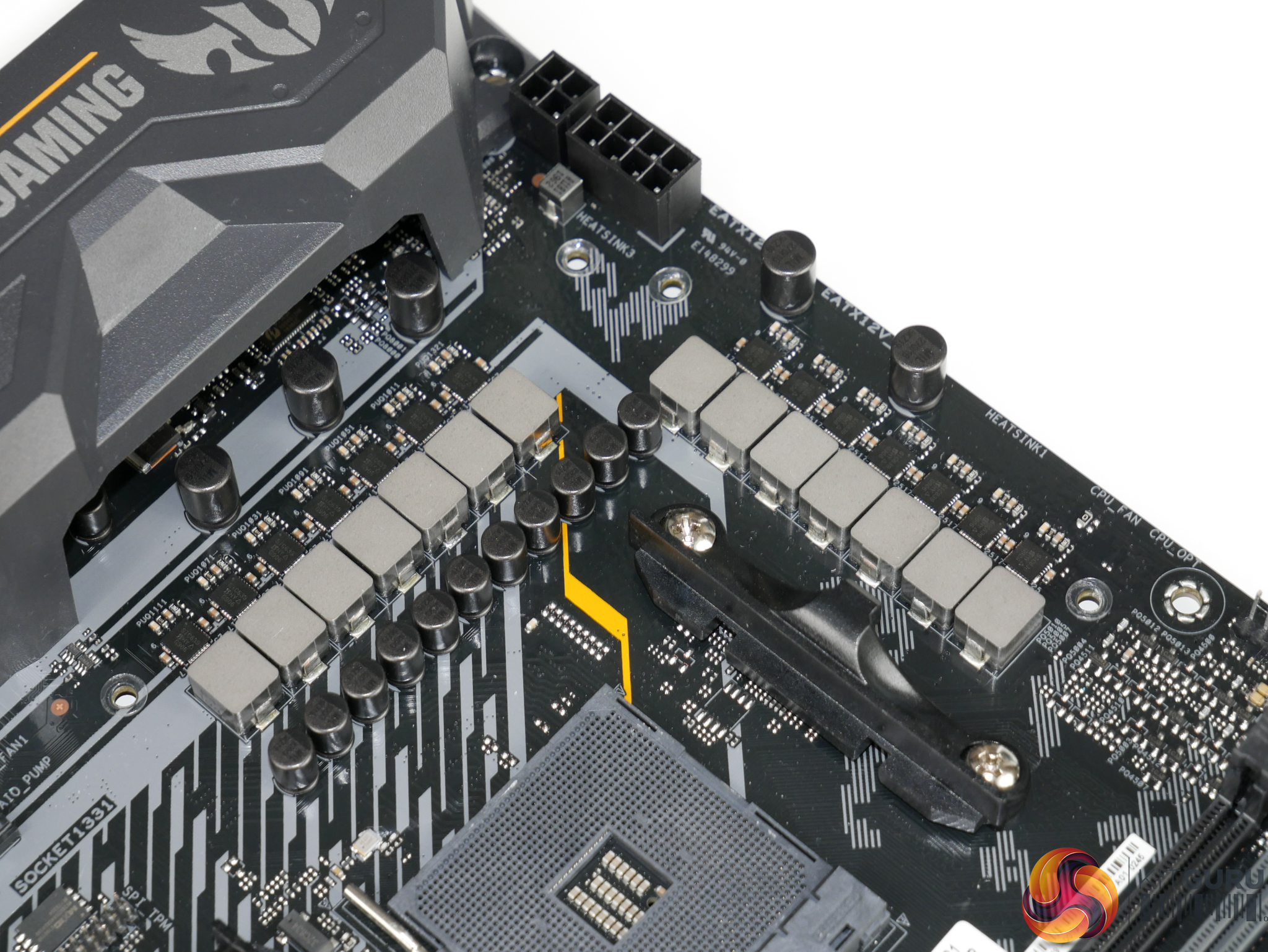
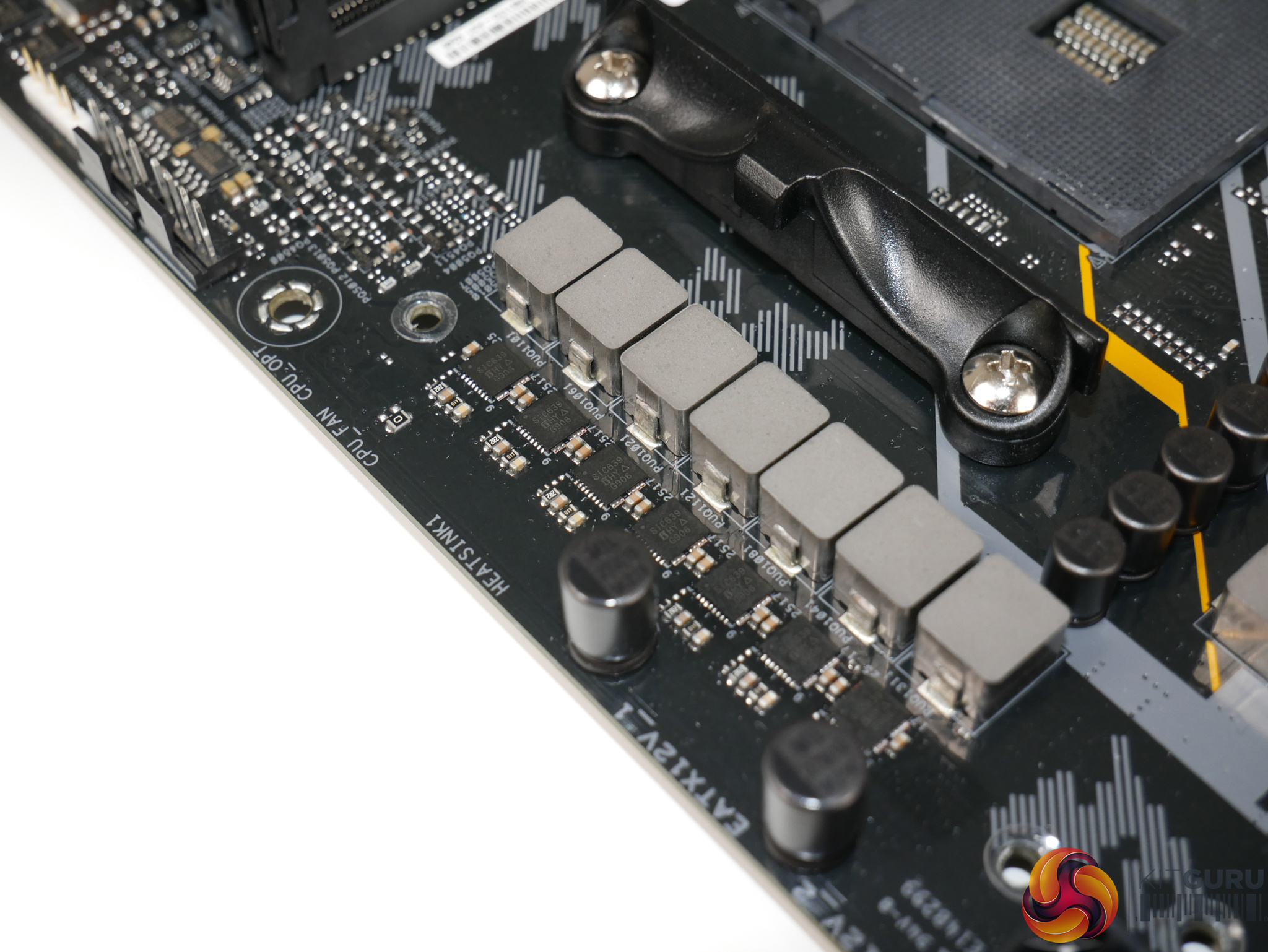
Focussing specifically on the 4×3, non-doubled CPU VCore power delivery system, ASUS is using a total of twelve Vishay SiC639 DrMOS power stages. These power stages are rated at ‘up to’ 50A of continuous current output just like we see from the SiC632 solutions and they look to be very slightly de-rated compared to the SiC634 alternatives.
Digging deeper into the spec sheet, the SiC639 looks to feature more focus on thermal monitoring compared to the SiC634 packages found on competing motherboards. The electronic block diagram shows an in-built thermal monitoring and warning function that features in the control loop. Either way, the SiC639 power stages look to be good solutions for a £210 AM4 motherboard, especially with the quantity of physical phases that ASUS deploys to balance the overall CPU load.
The two SoC phases uses the same SiC639 power stages and each electronic phase gets one power stage, not three like we see for the CPU VCore VRM. Rather than split the SoC VRM phases off into their own PCB section, ASUS deploys them on the top-left corner of the of the bank of 14 physically mounted phases.
Capacitor-wise, ASUS is using 5,000 hour rated ‘Black Metallic TUF caps’. While the headline 5,000 hour figure of these capacitors is pretty basic for a £210 motherboard, ASUS’ marketing material highlights an operating temperature of up to 125°C for the 5,000 hour rating. This is important, as the exponential-style curve will mean that the lifespan is mathematically likely to be higher than 5,000 hours at the usual rating temperature of 105°C. The operating life will be even longer when realistic running temperatures of 80°C or below are used.
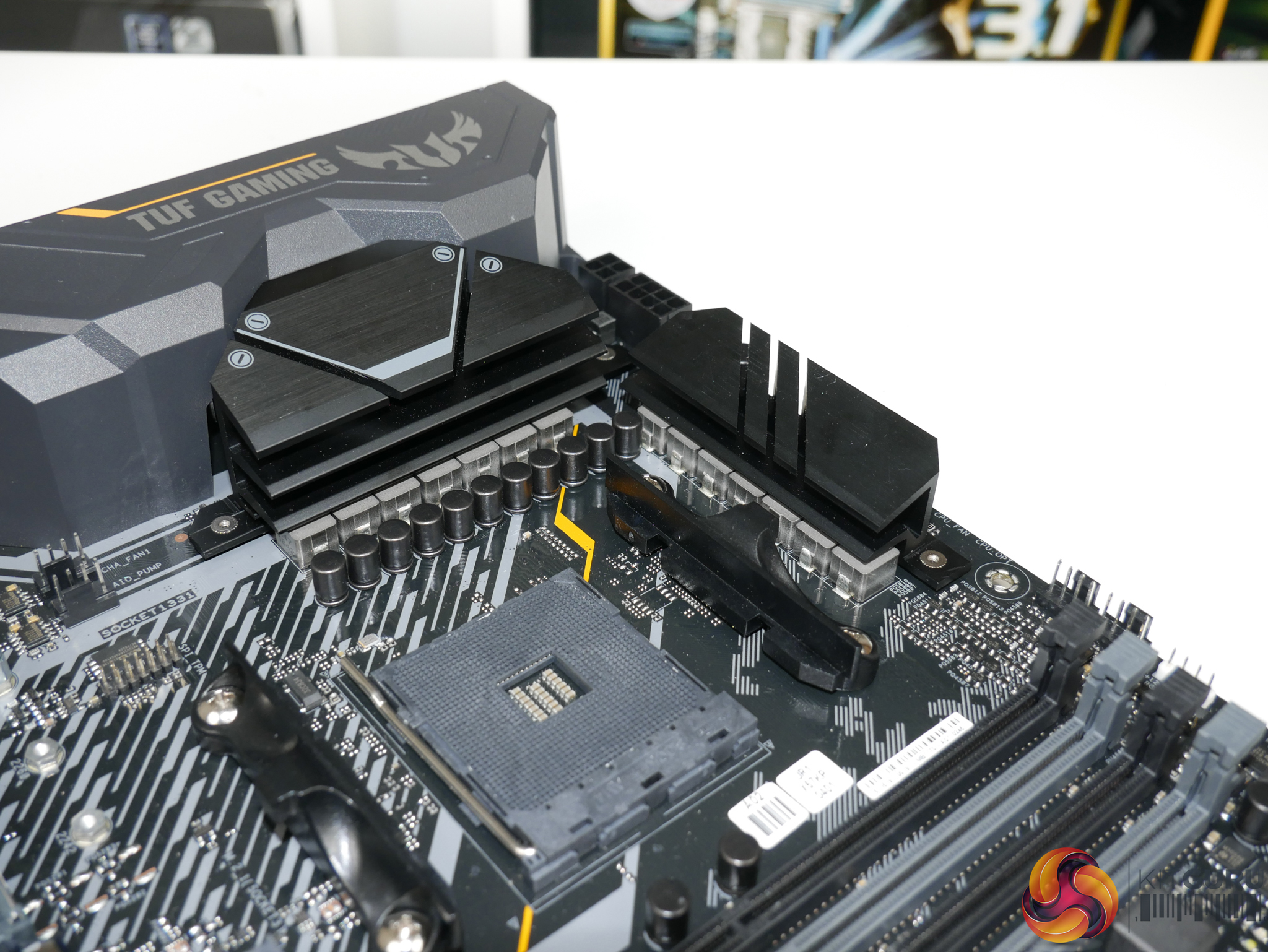

ASUS is clearly banking on efficient operation from the twelve physical CPU VCore VRM phases as the heatsinks deployed are poor. There’s no real effort to increase surface area in the direction of airflow by using fins. You get a few tiers or cut-outs on both of the metal heatsinks, but I wouldn’t say that significant effort has been put into designing an efficient heatsink. This is more of an aesthetic heatsink.
With that said, mounting pressure is strong thanks to the use of screws as a securing mechanism. The applied thermal pads also look to be well-specced and clearly aren’t too thick for their purpose.
ASUS actually deploys an additional thermal pad compared to what we’re used to see. This contacts the top of the inductors in an effort to draw heat away from them. How much use this will be is hard to say, as we don’t typically see thermal problems from chokes thanks to their higher surface area compared to MOSFETs helping them dump heat. Perhaps ASUS is thinking about motherboard comparisons using thermal imaging, at which point direct heatsink contact and therefore lower inductor temperature may show up as a positive.

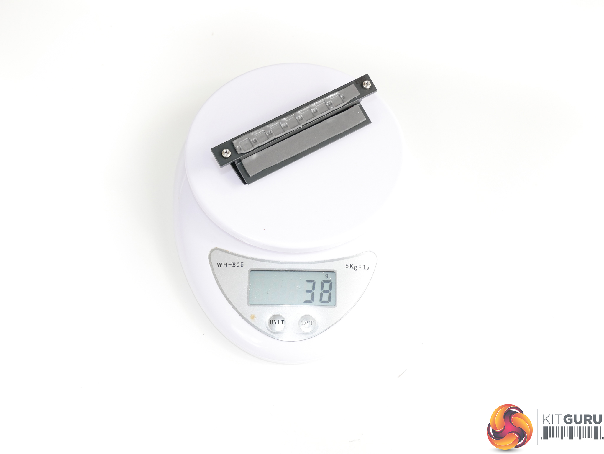
Weight wise, the left side VRM heatsink comes in at 75 grams while the top heatsink is a measly 38 grams. Again, ASUS looks to be banking on electrically efficient operation of the power stages to allow the small heatsinks to prove fit for purpose.
Compared to ASRock’s competitor, which has a higher mass of heatsink in total, ASUS actually has more heatsink mass allocated to the CPU VCore thanks to the mounting design. With six CPU power stages split to the left of the AM4 socket and six more above it, the two heatsinks are each tasked with cooling the CPU VRM MOSFETs, as opposed to just one of the heatsinks. This is a better design than ASRock’s bunched formation as it also allows thermal load from the power stages to be split across a larger area of the PCB, thus mitigating specific hotspot areas.
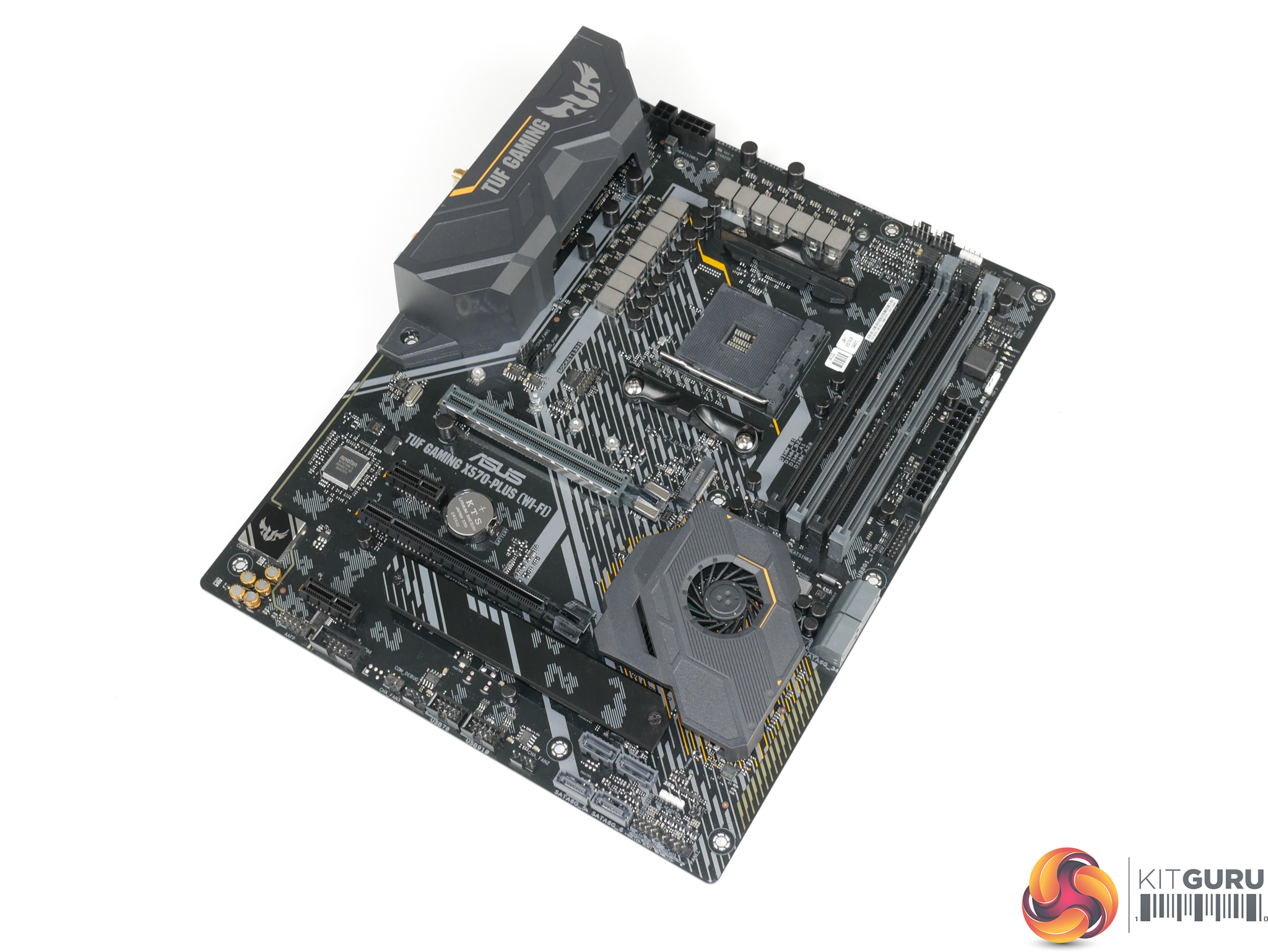
One area where ASUS deserves credit on this £210 X570 motherboard is the use of a six-layer PCB. The higher layer count should help to manage heat load into the PCB.