
ASUS TUF Gaming X570-Plus Wi-Fi
Moving on to ASUS’ TUF Gaming X570-Plus, we see the first of our twelve physical CPU VCore VRM solutions.
Our overclocked settings resulted in power draw that was practically identical to that of ASRock’s board at 245-255W under AIDA loading. We did not see any signs of VRM-induced CPU clock speed throttling.
Annoyingly, ASUS does not include data for VRM temperature sensor readings through software tools. This is despite the SiC639 DrMOS power stages featuring thermal monitoring capabilities. As such, we cannot make a comparison between our measured results and the software readings.
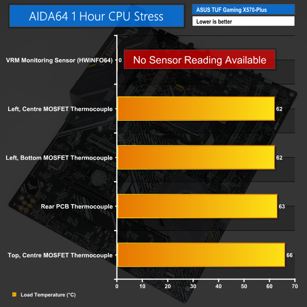
Looking at the MOSFET temperature performance, we saw a maximum temperature of 66°C, when normalised to 25°C ambient. Unsurprisingly, the highest temperature reading was displayed by the central power stage mounted above the CPU socket, beneath the small VRM heatsink. The central and lowest power stages mounted to the left of the CPU socket, beneath the larger cooler, operated around 4°C cooler at 62°C.
A maximum temperature of less than 70°C when mounted under ASUS’ anaemic heatsinks is a good result and speaks volumes about the TUF X570-Plus’ VRM solution. Balancing a hefty CPU load pushing close to 200W across twelve physical VRM phases allows the load per phase to be reduced, compared to lesser phase count solutions. This translates into solid operating temperatures, according to our results. As we also saw with ASRock’s board, the Vishay DrMOS power stages do a good job for this level of load.
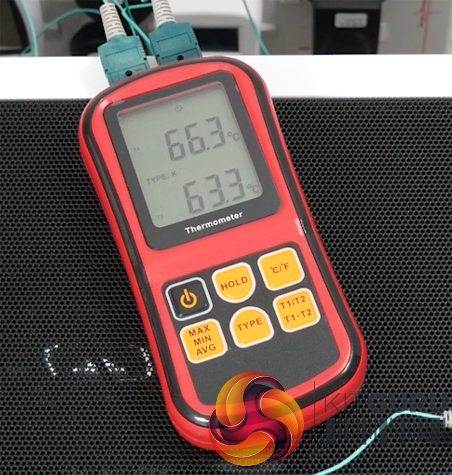
The rear PCB temperature, measured beneath the central MOSFET from the left-side bank, hit a maximum of 63°C when normalised to 25°C ambient. ASUS’ six-layer PCB looks to be handling heat soak from the MOSFETs well, as the PCB temperature is absolutely no cause for concern.
Also aided by the six-layer PCB is the cooling rate directly after load removal and system shut down. After five minutes, the MOSFETs were down to the mid-40s and the PCB cooled even quicker by dropping just below 40°C in this time period.
Overall, ASUS looks to have deployed a well-built power delivery solution on the TUF Gaming X570-Plus motherboard. Despite using a twelve-phase design that is only driven by four real phases without doublers, ASUS’ solution is clearly well-built for the heavy heat loads placed on it by an overclocked Ryzen 9 12-core chip.